

Page 1
Installation
video available at
Sanus.com
ML11 and LL11 Instruction Manual
ML11
LL11
We are here to help!
Please contact Customer Service with any questions.
Customer Service
Americas: 800-359-5520 • 952-225-6013 • info@sanus.com
UK: 0800-056-2853
Europe, Middle East, and Africa: +31 (0) 495 580 852 • europe.sanus@milestone.com
Asia Paci c: 86 755 8996 9226 • sanus.ap@milestone.com
SANUS • 6436 City West Parkway • Eden Prairie, MN • 55344 • USA
©2014 Milestone AV Technologies. All rights reserved. Sanus is a division of Milestone.
All other brand names or marks are used for identi cation purposes and are trademarks of their respective owners.
sanus.com
Page 2
IMPORTANT SAFETY INSTRUCTIONS – SAVE THESE INSTRUCTIONS – PLEASE READ ENTIRE MANUAL PRIOR TO USE
OR
OPT
OR
OPT
OR
OPT
OR
OPT
OR
OPT
OR
OPT
OR
OPT
OR
OPT
OR
OPT
OR
OPT
OR
OPT
OR
OPT
OR
OPT
OR
OPT
English - How to use this manual
For best results, reference both the text and illustrations. Cut along
the dashed lines to match your language with the illustrations.
Select one item or the other.
This item is optional
English Text Pages 3-11
Français - Utilisation de ce guide
Pour obtenir de meilleurs résultats, reportez-vous à la fois au texte
et aux illustrations. Couper le long de la ligne pointillée pour faire
correspondre les illustrations à votre langue de préférence.
Sélectionnez un article ou l’autre.
Cet article est facultatif.
Texte français page 12-13
Deutsch - Verwendung dieses Handbuchs
Die Montage ist am einfachsten, wenn Sie den Text und die
Abbildungen zusammen verwenden. Schneiden Sie daher den Text
in Ihrer Sprache aus (gestrichelte Linien), um ihn den Abbildungen
gegenüberstellen zu können.
Sie haben die Wahl zwischen einem Element oder einem anderen.
Dieses Element ist optional.
Deutscher Text Seite 14-15
Suomi - Oppaan käyttäminen
Saavutat parhaan tuloksen tutustumalla sekä tekstiin että kuviin.
Leikkaa katkoviivaa pitkin ja yhdistä kuvat ja suomenkielinen teksti.
Valitse toinen vaihtoehdoista.
Tämä vaihtoehto on valinnainen.
Suomenkielinen teksti on sivulla 24-25
Svenska - Så här använder du denna bruksanvisning
För bästa resultat, hänvisa till både text och bilder när du använder
denna bruksanvisning. Klipp längs de streckade linjerna för att
matcha ditt språk med bilderna.
Välj ett objekt eller det andra.
Detta objekt är valfritt.
Svensk text sida 26-27
Русский - Как пользоваться данной инструкцией
Для получения наилучшего результата ориентируйтесь
как на текст, так и на иллюстрации, приведенные в данном
руководстве. Отрежьте по пунктирной линии, чтобы совместить
нужный язык с иллюстрациями.
Выберите один из вариантов.
Эта деталь может не входить в комплект поставки.
Русский текст: стр. 28-29
Español - Cómo usar este manual
Para obtener mejores resultados, consulte el texto y las ilustraciones.
Corte por las líneas discontinuas para hacer coincidir su idioma con
las ilustraciones.
Seleccione uno de los elementos.
Este elemento es opcional.
Texto en español página 16-17
Português -Como usar este manual
Para obter melhores resultados, consulte o texto e as ilustrações.
Recorte nas linhas tracejadas para combinar seu idioma com as
ilustrações.
Selecione um item ou o outro.
Este item é opcional.
Texto em português Página 18-19
Nederlands - Gebruik van deze handleiding
Voor de beste resultaten moet u zowel de tekst als de illustraties
raadplegen. Gebruik de stippellijnen om uw taal bij de illustraties
te plaatsen.
Selecteer een van beide items.
Dit item is optioneel.
Nederlandse tekst op pagina 20-21
Italiano - Uso del manuale
Per risultati ottimali, fare riferimento sia al testo che alle illustrazioni
di questo manuale. Tagliare lungo le linee tratteggiate per abbinare
il testo nella propria lingua alle illustrazioni.
Selezionare uno o l’altro elemento.
Questo elemento è opzionale.
Testo in italiano alle pagine 22-23
Polski - Jak używać tej instrukcji
W celu uzyskania najlepszych rezultatów, korzystając z tej instrukcji,
należy zwrócić uwagę zarówno na tekst, jak i na ilustracje. Przeciąć
wzdłuż przerywanych linii w celu dopasowania języka do ilustracji.
Wybrać jedną pozycję lub drugą.
Ta pozycja jest opcjonalna.
Tekst w języku polskim na stronach 30-31
Česky - Jak používat tuto příručku
Nejlepších výsledků dosáhnete, budete-li při používání této příručky
srovnávat text s ilustracemi. Odstřihněte podél čárkované čáry, aby
bylo možno české instrukce přiřadit k ilustracím.
Vyberte si jednu nebo druhou položku.
Tato položka je volitelná.
Český text se nachází na straně 32-33
日本語 - このマニュアルの使い方
組み立てをうまく行うためには、説明文とイラストの両方を参照してくだ
さい。点線に沿って切り取ると、ご使用の言語とイラストが一致します。
どちらか片方の品目を選択してください。
この品目は、オプションです。
日本語は
中文 - 如何使用本说明书
请同时参阅文字说明和插图以获得最佳阅读效果。请沿着虚线裁剪,
将您的语言与插图匹配起来。
34 -35
ページ
选择一项或另一项。
此项可选。
中文文字说明请参见第 36 -37页
2
6901-172002 02
Page 3
English
Speci cations
Weight capacity-includes TV and any accessories-DO NOT EXCEED:
ML11 45.4 kg (100 lb.)
LL11 68 kg (150 lb.)
CAUTION: Avoid potential personal injuries and property damage!
Do not use this product for any purpose not explicitly speci ed by manufacturer.
The wall must be capable of supporting ve times the weight of the monitor and mount combined.
This product includes directions and hardware for use with wood stud, solid concrete and concrete block walls. For information on how
to use this product with steel stud walls contact Customer Service and ask about the SSMK1 steel stud mounting kit.
If you do not understand these instructions, or have doubts about the safety of the installation, assembly or use of this product, contact
manufacturer Customer Service or call a quali ed contractor.
Manufacturer is not responsible for damage or injury caused by incorrect assembly or use.
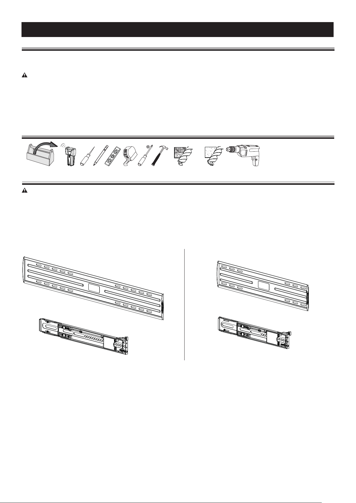
Required Tools
5mm
(3/16 in.)
10mm
(3/8 in.)
Supplied Parts and Hardware
WARNING: This product contains small items that could be a choking hazard if swallowed.
Before starting assembly, verify all parts are included and undamaged. If any parts are missing or damaged, do not return the damaged
item to your dealer; contact Customer Service. Never use damaged parts! NOTE: M4, M5, M6, or M8 describes the diameter, mm describes
the length of screws that are labeled M# X ##mm. Not all hardware included will be used.
LL11 ML11
[01] x 1
[01] x 1
[02] x 2
6901-172002 02
[02] x 2
3
Page 4
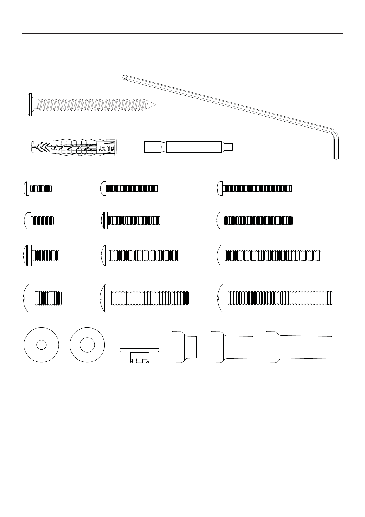
Supplied Parts and Hardware Continued
M7 x 70 mm
[03] x 4
[06] x 1
[04] x 4
M4 x 12mm
[07] x 4
M5 x 12mm
M4 x 30mm M4 x 40mm
[08] x 4 [09] x 4
M5 x 30mm
[10] x 4 [11] x 4
M6 x 14mm
[13] x 4
M8 x 16mm
[16] x 4
M6 x 40mm
[14] x 4 [15] x 4
M8 x 45mm
[17] x 4
[05] x 1
M5 x 40mm
[12] x 4
M6 x 55mm
M8 x 60mm
[18] x 4
M4 / M5 M6 / M8
[19] x 4
4
14mm 24mm 38mm
[24] x 4[23] x 4[22] x 4[21] x 4[20] x 4
6901-172002 02
Page 5
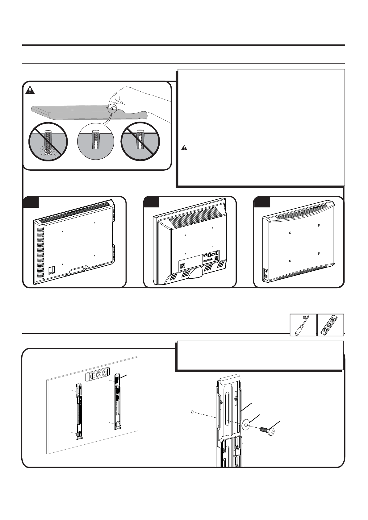
1 Select TV Hardware and Mount TV Brackets
1-1 Select the hardware diameter and length
Your TV type will help you determine which hardware con guration to
use. Match your type of TV to the suggested hardware con guration
on the next page.
A. Installation option without spacers (TVs with at backs)
B. Installation option using 14mm spacers (TVs with irregular backs)
C. Installation option using 24mm or 38mm spacers (For TVs with
irregular backs that require more length than the 14mm spacer
provides.)
Hand thread screws into the threaded inserts on the back of your TV
to determine the correct screw diameter (M4, M5, M6, or M8).
CAUTION: Avoid potential personal injuries and property
damage! Verify that there are adequate threads to secure the brackets
to the monitor. If you encounter resistance, stop immediately
and contact customer service. Use the shortest screw and spacer
combination to accommodate your needs. Using hardware that is too
long may damage your TV.
A
B C
1-2 Attach Brackets to a TV with a fl at back
Con rm that the brackets are level on the back of the TV.
If you require additional space for cables, recesses, or protrusions,
choose one of the con gurations below.
[02]
6901-172002 02
[02]
[19, 20]
[07, 10, 13, 16]
5
Page 6
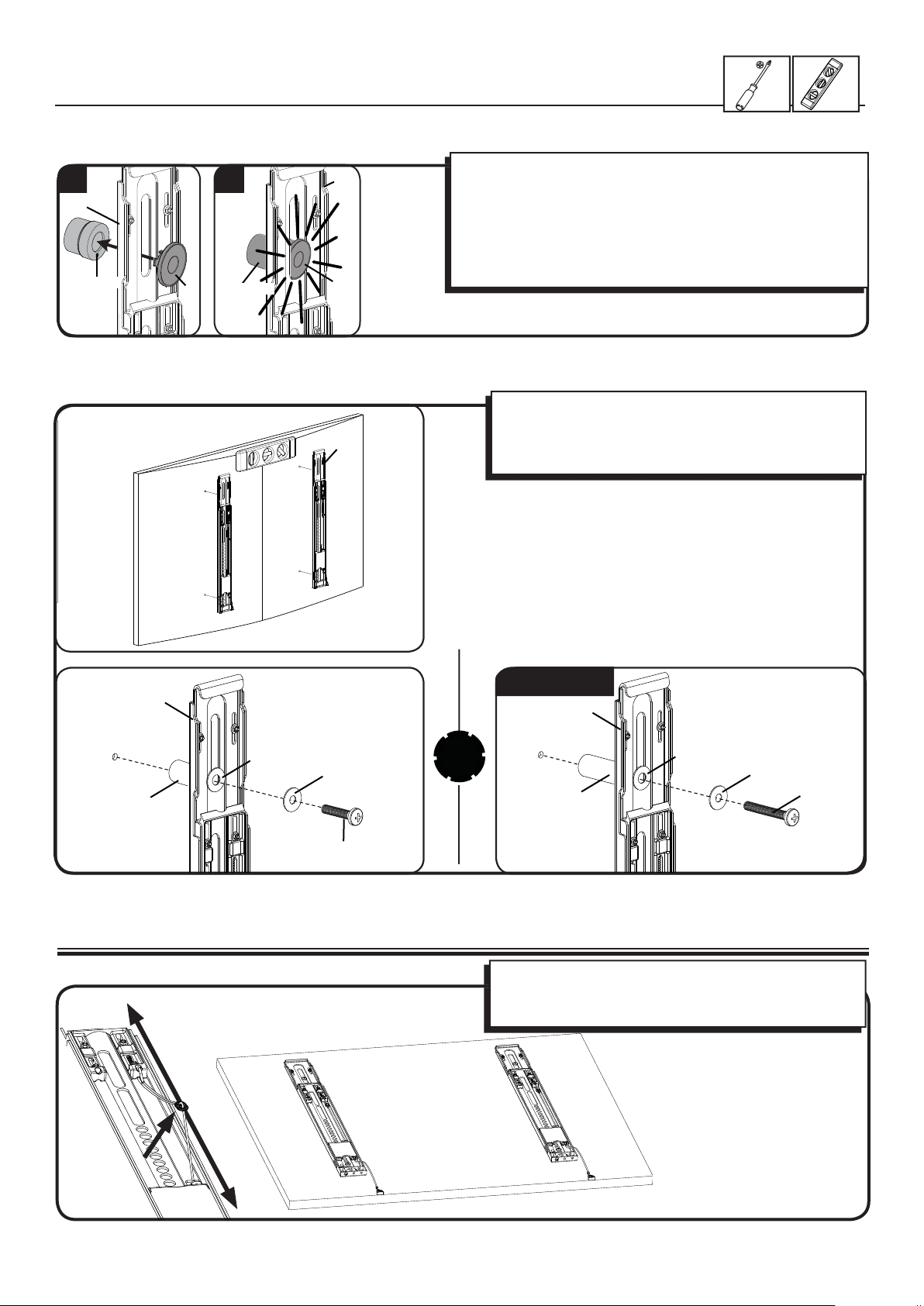
1-2 Attach brackets to a TV with an irregular back
OR
1 2
[02]
[22, 23, 24]
[21]
[22, 23, 24]
[02]
[21]
[02]
1. Push the shoulder washer [21] through the appropriate openings
of the brackets [02].
2. Snap shoulder washer [21] into the spacer you selected in step
1-1.
If your TV has a curved or obstructed back, or if you need more room
to accommodate cables, recesses, or protrusions, use either the
14mm, 24mm, or 38mm spacer [22, 23, or 24].
Con rm that the brackets are level on the back of the TV.
Standard con gurations are shown. For special applications,
or if you are uncertain about your hardware selection, contact
Customer Service.
[02]
[21]
[22, 23]
[08, 09, 11, 12, 14, 17]
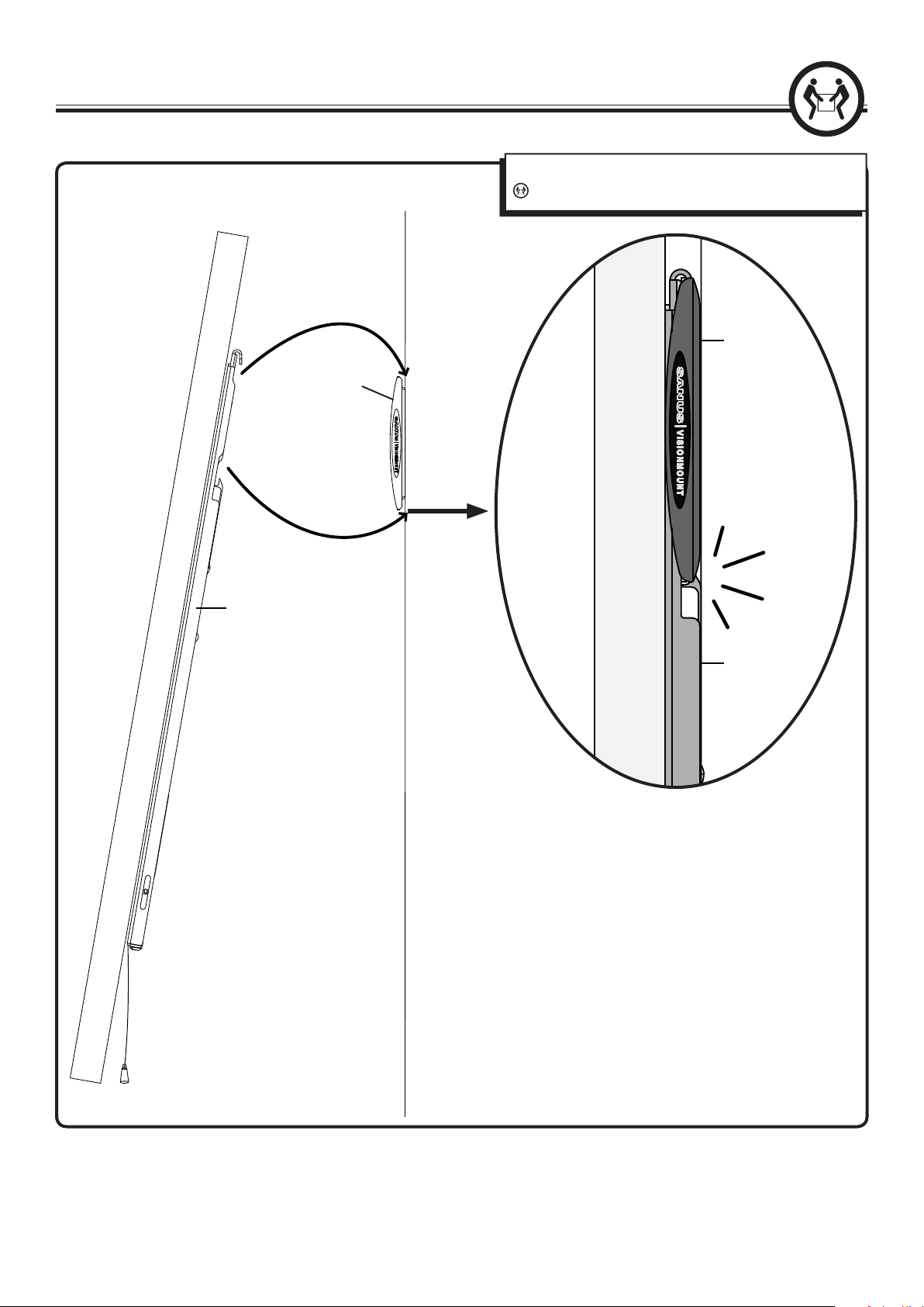
2 Adjust Cord Length
[19, 20]
M6/M8 ONLY!
[02]
[21]
[20]
[24]
To adjust cord length, gently pull the cord away from the
brackets.
For ease of access, cords should be level with bottom of TV.
[15, 18]
6
6901-172002 02
Page 7
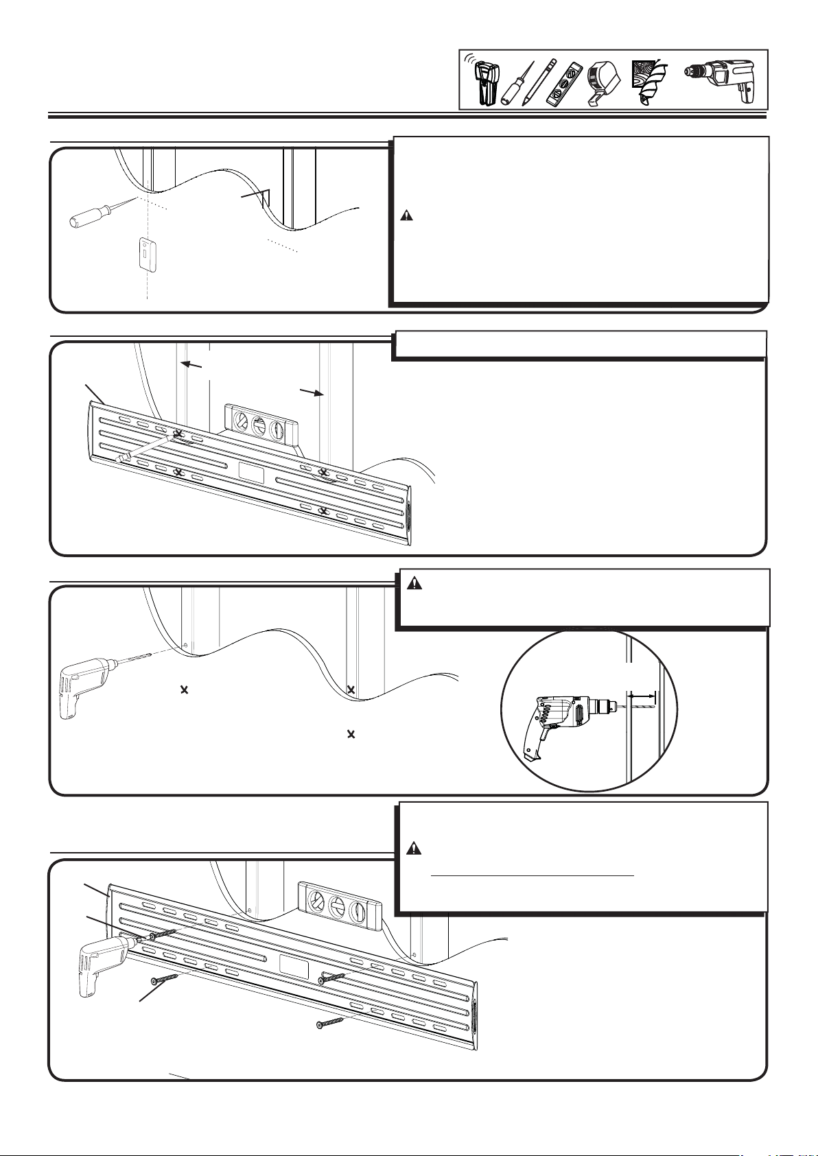
3 Mount the Wall Plate
Wood Stud Mounting
5 mm
(3/16 in.)
3-1 Locate studs
≤ 16 mm
3-2 Mark the wall
[01]
(5/8 in.)
LL11
406-609 mm (16-24 in.)
ML11
406 mm (16 in.)
For assistance in determining wall plate location, see Height Finder at
sanus.com.
Locate studs. Verify the center of the stud(s) using an awl or edge to
edge stud nder.
CAUTION: Avoid potential personal injuries and property
damage!
Drywall covering the wall must not exceed 16 mm (5/8 in.).
Minimum wood stud size: common 51 x 102 mm (2 x 4 in.)
nominal 38 x 89 mm (11/2 x 31/2 in.). ).
Level the wall plate [01] and mark the hole locations.
3-3 Drill pilot holes
3-4 Tighten lag bolts
[01]
[05]
CAUTION: Avoid potential injuries or property damage! Pilot
holes MUST be drilled to a depth of 70 mm (2¾ in.), using a 5mm
(3/16 in.) diameter drill bit.
70mm
(2¾ in.)
Using a drill and the allen driver bit [05] tighten lag bolts [03] only
until they are pulled rmly against the wall plate.
CAUTION:
DO NOT over-tighten the lag bolts [03].
Tighten the lag bolts only until they are pulled rmly against the
wall plate [01].
Avoid potential injuries or property damage!
[03]
6901-172002 02
7
Page 8
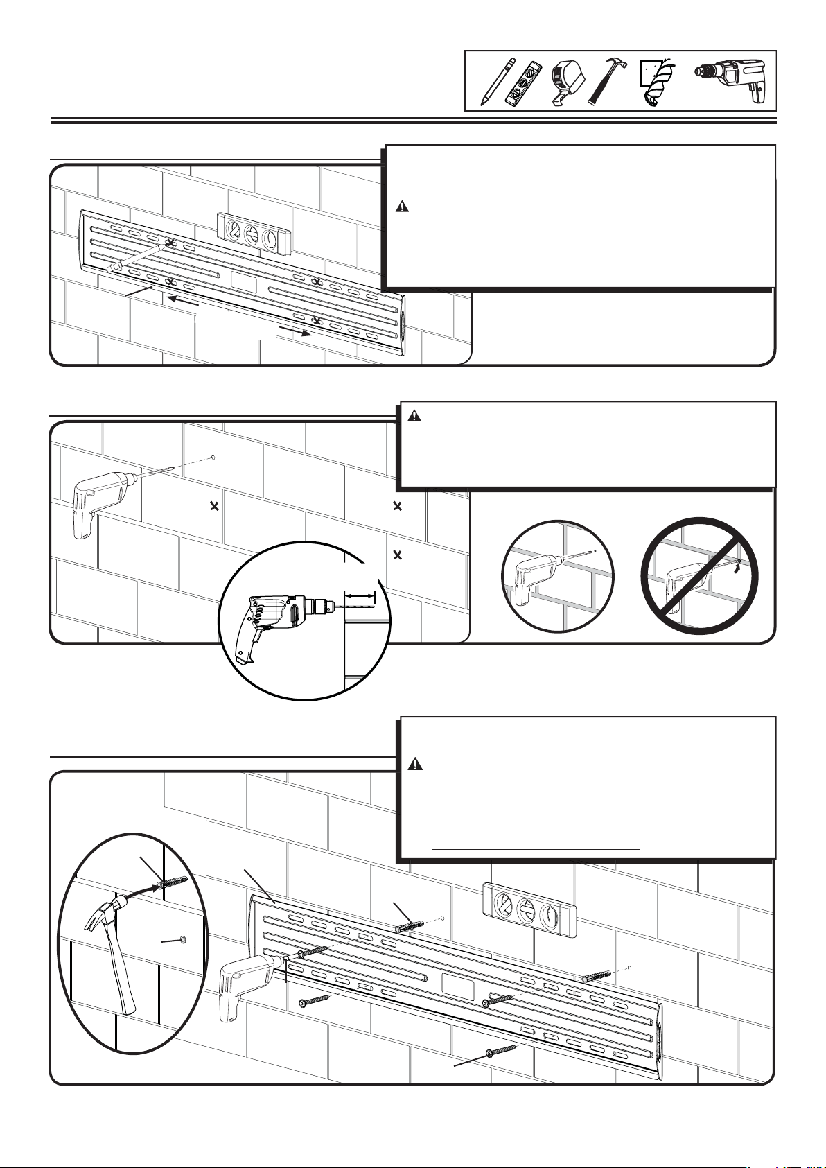
3 Mount the Wall Plate
Solid Concrete or Concrete Block
10 mm
(3/8 in.)
3-1 Mark the wall
[01]
406 mm (16 in.)
3-2 Drill pilot holes
For assistance in determining wall plate location, see Height Finder at
sanus.com.
Level the wall plate [01] and mark the hole locations.
CAUTION:
Mount the wall plate [01] directly onto the concrete surface.
Minimum solid concrete thickness: 203mm (8 in.).
Minimum concrete block size: 203 x 203 x 406 mm (8 x 8 x 16 in.).
Minimum space between fasteners: 406 mm (16 in.).
CAUTION:
Pilot holes MUST be drilled to a depth of 75 mm (3 in.) using a 10
mm (3/8 in.) diameter drill bit.
Never drill into the mortar between blocks.
Avoid potential injuries or property damage!
Avoid potential injuries or property damage!
3-3 Insert anchors and lag bolts
[04]
[01]
[04]
75 mm
(3 in.)
Insert lag bolt anchors [04]. Then insert lag bolts [03] using a drill and
the allen driver bit [05].
CAUTION:
the lag bolt. To avoid potential injuries or property damage:
Be sure the anchors [04] seat ush with the concrete surface.
Tighten the lag bolts [03] only until the they are pulled rmly
against the wall plate [01].
DO NOT over-tighten the lag bolts [03].
[04]
Improper use could reduce the holding power of
[05]
[03]
8
6901-172002 02
Page 9
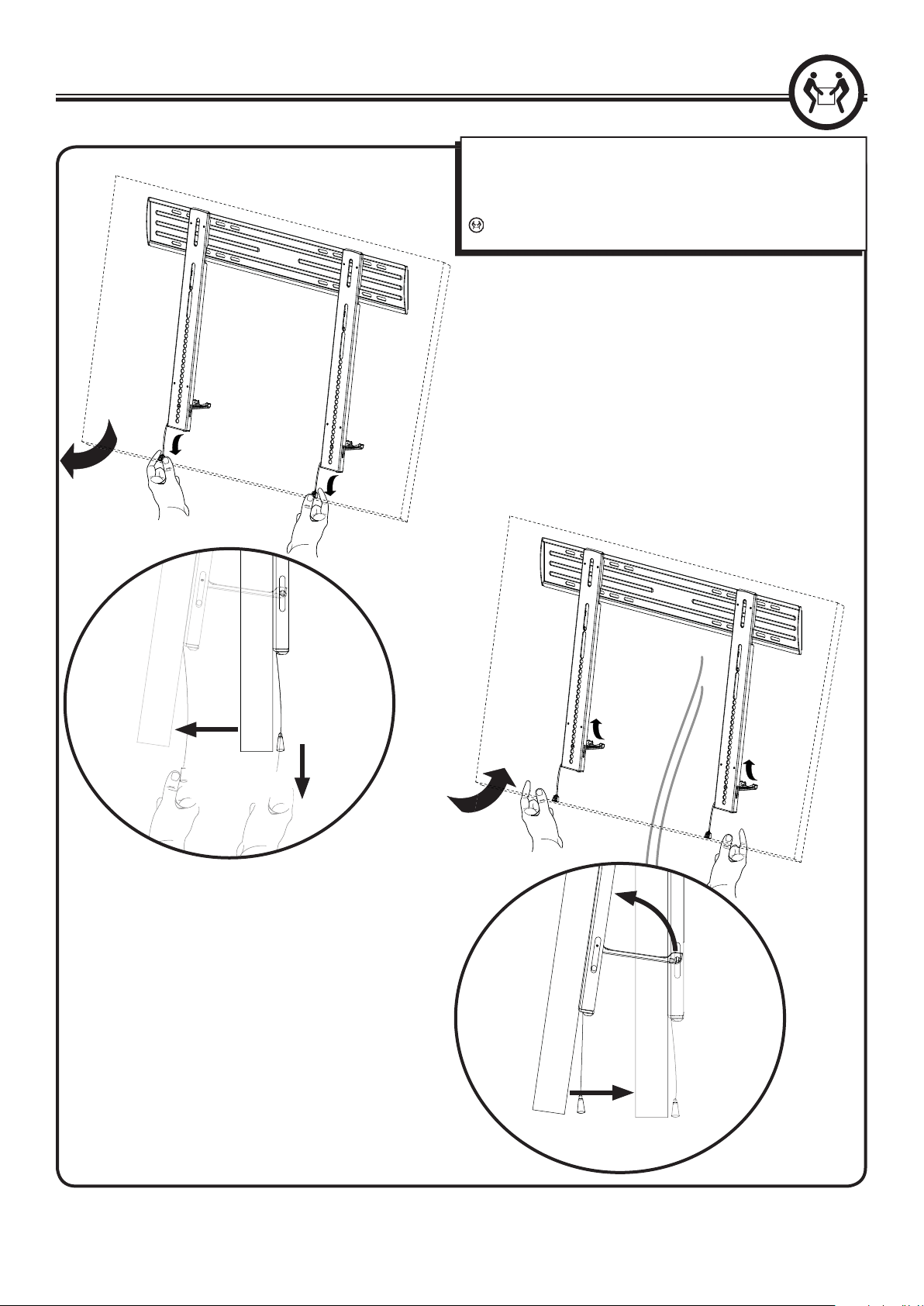
4 Hang TV onto the Wall Plate
Hang your TV onto the wall plate [01].
[01]
HEAVY! You will need assistance with this step.
[01]
[02]
[02]
6901-172002 02
9
Page 10
5 Manage Cables
Pull down on cord to release clickstands.
Gently pull the TV away from the wall. Clickstands will fall into place.
Complete cabling.
Push clickstands up and ease the TV back toward the wall.
Assistance is recommended for this step.
10
6901-172002 02
Page 11
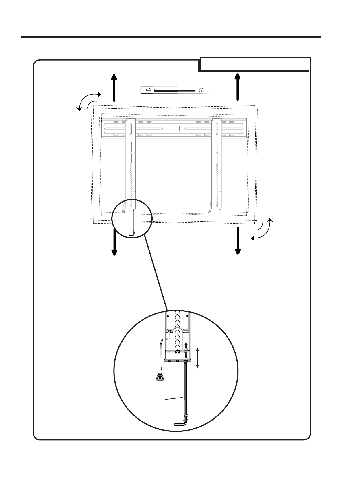
6 Make Adjustments
Adjust level of TV using post installation ProSet.
±2.5
o
± 12.7 mm
(.5 in.)
± 12.7 mm
(.5 in.)
±2.5
o
6901-172002 02
± 12.7 mm
(.5 in.)
[06]
11
Page 12
Français
CONSIGNES DE SÉCURITÉ IMPORTANTES – CONSERVEZ CES INSTRUCTIONS – VEUILLEZ LIRE ATTENTIVEMENT LE MANUEL AVANT
D’UTILISER CE PRODUIT
Caractéristiques techniques Voir à la page 3
Capacité de charge – NE PAS DÉPASSER: incluant le téléviseur et tous les accessoires.
ML11 45 kg (100 lb.)
LL11 68 kg (150 lb.)
ATTENTION: Évitez les dommages matériels et les blessures!
Ne pas utiliser ce produit à d’autres ns que celles spéci ées par le fabricant.
Le mur doit pouvoir supporter cinq fois le poids total du moniteur et du support.
Ce produit n’est pas conçu pour être utilisé sur des murs dont les montants sont en métal!
Si vous ne comprenez pas toutes ces instructions ou si vous avez des doutes sur la sécurité de l'installation, du montage ou de l’utilisation de ce produit,
veuillez contacter un installateur quali é ou le service à la clientèle du fabricant.
Le fabricant n’est pas responsable des blessures ou des dommages causés par une mauvaise utilisation ou un montage incorrect.
Outils nécessaires Voir à la page 3
Pièces et quincaillerie fournies
Voir à la page 3-4
AVERTISSEMENT: Ce produit contient de petites pièces qui peuvent représenter un risque d’étou ement.
Avant de commencer l’assemblage, assurez-vous que toutes les pièces sont présentes et qu’elles ne sont pas endommagées. Si une pièce est manquante ou
endommagée, ne retournez pas les pièces endommagées à votre revendeur. Contactez plutôt le service clientèle. N’utilisez jamais de pièces endommagées!
REMARQUE: M4, M5, M6, ou M8 décrit le diamètre et mm décrit la longueur des vis qui sont identi ées M0 X 00mm. Les pièces comprises ne doivent pas
nécessairement être toutes utilisées.
1 Sélectionnez la quincaillerie et le support de xation pour le
téléviseur Voir à la page 5
1-1 Sélectionnez le diamètre et la longueur de la quincaillerie Voir à la page 5
Le type de téléviseur vous aidera à choisir la con guration de la quincaillerie à utiliser. Faites correspondre votre type de téléviseur à l'une des con gurations
de quincaillerie suggérées à la page suivante.
A. Option d'installation sans entretoises (téléviseur à dos plat).
B. Option d'installation avec des entretoises de de 14mm (téléviseur avec dos irrégulier)
C. Option d'installation avec des entretoises de 24mm 38mm (pour les téléviseurs avec un dos irrégulier qui nécessitent plus long que les 14mm donnés par
les entretoises.)
Serrez à la main les vis dans les ori ces letées au dos du téléviseur a n de déterminer le diamètre de vis approprié (M4, M5, M6, ou M8).
ATTENTION: Évitez les dommages matériels et les blessures! Assurez-vous qu’il y a su samment de lets pour installer solidement les supports sur
le moniteur. Si vous sentez une résistance, arrêtez immédiatement et contactez le Service à la clientèle. Utilisez la combinaison la plus courte possible de vis et
d’entretoise nécessaire. L'utilisation d'une quincaillerie trop longue pourrait endommager le téléviseur.
1-2 Attachez les brides de montage au téléviseur dont l’arrière est plat Voir à la page 5
Assurez-vous que les supports sont l’horizontale (à niveau) derrière le téléviseur.
Si vous avez besoin de plus d’espace à cause des câbles, des creux ou des protubérances, sélectionnez l'une des con gurations ci-dessous.
1-2 Attachez les brides de montage au téléviseur avec dos irrégulier Voir à la page 6
1. Poussez la rondelle à épaulement [21] dans les ori ces appropriés des supports [02].
2. Pressez la rondelle à épaulement [21] dans l’entretoise que vous avez sélectionné à l'étape 1-2.
Si le dos de votre téléviseur est incurvé ou obstrué, ou si vous avez besoin d'un espace plus grand pour les câbles, les creux ou les protubérances, utilisez les
entretoises de 14mm, 24 mm ou 38mm [22, 23, ou 24].
Assurez-vous que les supports sont l’horizontale (à niveau) derrière le téléviseur.
Les con gurations standard sont illustrées. Consultez le Service à la clientèle pour toute application particulière ou si vous avez des doutes quant à la
quincaillerie à utiliser.
2 Réglez la longueur du câble Voir à la page 6
Pour régler la longueur du cordon, tirez celui-ci délicatement en l'éloignant des xations.
Pour faciliter l’accès, les câbles doivent être au même niveau que le bas du téléviseur.
12
6901-172002 02
Page 13

3 Installation sur des murs avec montants de bois Voir à la page 7
3-1 Trouvez les montants Voir à la page 7
Pour obtenir de l'aide a n de déterminer l’emplacement de la plaque murale, consultez le site sanus.com sous la rubrique «Height Finder».
Véri ez le centre de chaque montant à l’aide d’un poinçon ou d’un clou n, ou utilisez un localisateur bord à bord.
ATTENTION: Évitez les dommages matériels et les blessures!
L’épaisseur du matériau de revêtement de mur ne doit pas excéder 16mm (5/8po).
Dimension minimale du montant de bois: commune 51x102mm (2x4po) (nominale 38x75mm/1,5x3po).
3-2 Faites des marques sur le mur Voir à la page 7
Mettez la plaque murale [01] à niveau et marquez les emplacements des trous.
3-3 Percez les trous de guidage Voir à la page 7
ATTENTION: Les avant-trous DOIVENT être percés à une profondeur de 70mm (2,75 po) à l’aide d’un foret de 5mm (3/16po).
3-4 Serrez les boulons tire-fonds Voir à la page 7
À l’aide d’une perceuse et d’un embout d’entraînement Allen [05] serrez les boulons tire-fond [03].
ATTENTION:
NE PAS trop serrer les boulons tire-fond [03].
Serrez les boulons tire-fond [03] jusqu'à ce qu’ils s’appuient fermement sur la plaque murale [01].
Évitez tout dommage matériel ou blessure!
3 Montage sur béton Voir à la page 8
3-1 Faites des marques sur le mur Voir à la page 8
Pour obtenir de l'aide a n de déterminer l’emplacement de la plaque murale, consultez le site sanus.com sous la rubrique «Height Finder».
Mettez la plaque murale [01] à niveau et marquez les emplacements des trous.
ATTENTION:
Montez la plaque murale [01] directement sur la surface de béton.
Épaisseur minimale du béton coulé: 203mm (8po)
Dimension minimale du bloc de béton: 203x203x406mm (8x8x16po)
Évitez tout dommage matériel ou blessure!
3-2 Percez les trous de guidage Voir à la page 8
ATTENTION:
Les avant-trous DOIVENT être percés à une profondeur de 75mm (3po) à l'aide d'un foret de 10mm (3/8po) de diamètre.
Ne jamais percer dans le mortier entre les blocs.
Évitez tout dommage matériel ou blessure!
3-3 Insérez les douilles à expansion et les boulons tire-fond Voir à la page 8
Insérez les douilles à expansion des boulons tire-fond [04]. Insérez ensuite les boulons tire-fond [03] à l’aide d’une perceuse et d’un embout d’entraînement
Allen [05].
ATTENTION:
Évitez tout dommage matériel ou blessures !
Assurez-vous que les douilles à expansion [04] ne dépassent pas de la surface de béton.
Serrez les boulons tire-fond [03] jusqu'à ce qu'ils s'appuient fermement sur la plaque murale [01].
NE PAS trop serrer les boulons tire-fond [03].
Évitez tout dommage matériel ou blessure! Une utilisation inadéquate peut réduire la force de rétention du boulon tire-fond.
4 Accrochez le téléviseur à la plaque murale Voir à la page 9
Accrochez le téléviseur à la plaque murale [01].
5 Gestion des câbles Voir à la page 10
Tirez sur le câble vers le bas pour déverrouiller le ClickStands.
Éloignez doucement le téléviseur du mur. Le ClickStands se mettra en place.
Terminez le raccordement des câbles.
Tirez sur le câble vers le bas pour soulever le ClickStands.
Ramenez doucement le téléviseur au mur. Le ClickStands coulissera vers le haut.
6 ProSet – Mise au niveau après l’installation Voir à la page 11
6901-172002 02
13
Page 14

Deutsch
WICHTIGE SICHERHEITSHINWEISE – BEWAHREN SIE DIESE HINWEISE SORGFÄLTIG AUF – LESEN SIE VOR DEM GEBRAUCH DES
PRODUKTS BITTE DAS GESAMTE HANDBUCH
Spezi kationen Siehe Seite 3
Höchstzulässiges Gesamtgewicht-NICHT ÜBERSCHREITEN: inkl. Fernseher und Zubehör.
ML11 45 kg (100 lb.)
LL11 68 kg (150 lb.)
VORSICHT: Vermeiden Sie Verletzungen und Sachschäden!
Verwenden Sie dieses Produkt nur für den vom Hersteller ausdrücklich angegebenen Zweck.
Die Wand muss das Fün ache des Gesamtgewichts von Monitor und Halterung tragen können.
Dieses Produkt ist nicht für die Verwendung an Wänden mit Metallträgern geeignet!
Falls Sie diese Anleitung nicht verstehen sollten oder Zweifel bezüglich der sicheren Montage, des Zusammenbaus oder der Verwendung des Produkts
haben, kontaktieren Sie den Kundendienst des Herstellers oder einen quali zierten Auftragnehmer.
Der Hersteller haftet nicht für Schäden oder Verletzungen, die durch falsche Montage oder Verwendung verursacht werden.
Erforderliche Werkzeuge Siehe Seite 3
Mitgelieferte Teile und Befestigungsmaterialien
Siehe Seite 3-4
WARNUNG: Dieses Produkt enthält kleine Teile, die beim Verschlucken zum Erstickungstod führen können.
Prüfen Sie vor Montagebeginn, ob alle Teile vorhanden und unbeschädigt sind. Falls Teile fehlen oder beschädigt sind, bringen Sie das Produkt nicht zum
Händler zurück, sondern wenden Sie sich an den Kundendienst. Verwenden Sie niemals beschädigte Teile!
HINWEIS: Bei Schrauben mit der Bezeichnung M0 X 00mm steht M4, M5, M6 oder M8 für den Durchmesser und mm für die Länge. Es wird nicht das gesamte
mitgelieferte Befestigungsmaterial verwendet.
1 Auswählen der Befestigungsmaterialien und Montieren der
Anschlussplatten für den Fernseher Siehe Seite 5
1-1 Wählen Sie Länge und Durchmesser der Befestigungsmaterialien Siehe Seite 5
Ihr Fernsehertyp wird Ihnen beim Bestimmen der richtigen Kon guration der Befestigungsmaterialien behil ich sein. Stimmen Sie Ihren Fernsehertyp mit den
Befestigungsmaterialien nach den auf der nächsten Seite angegebenen Kon gurationsvorschlägen ab.
A. Montage ohne Abstandhalter (Fernseher mit acher Rückseite)
B. Montage mit 14-mm-Abstandhaltern (Fernseher mit unebener Rückseite)
C. Montage mit 24-mm-38-mm-Abstandhaltern (Für Fernseher mit unebener Rückseite, für die 14-mm-Abstandhalter zu kurz sind.)
Bestimmen Sie den geeigneten Schraubendurchmesser (M4, M5, M6 oder M8), indem Sie die Schrauben mit der Hand in die Gewindeeinsätze an der
Rückseite Ihres Fernsehers schrauben.
VORSICHT: Vermeiden Sie Verletzungen und Sachschäden! Stellen Sie sicher, dass geeignete Gewindegänge für die Befestigung der Anschlussplatten
am Monitor vorhanden sind. Falls Sie auf Widerstand stoßen, brechen Sie die Montage unverzüglich ab und rufen Sie den Kundendienst an. Verwenden
Sie die kürzeste Schrauben-Abstandhalter-Kombination, die unter den gegebenen Montagebedingungen möglich ist. Durch die Verwendung von zu langen
Schrauben kann Ihr Fernseher beschädigt werden.
1-2 Befestigen der Anschlussplatten an einem Fernseher mit acher Rückseite Siehe Seite 5
Vergewissern Sie sich, dass die Anschlussplatten ach auf der Rückseite des Fernsehers anliegen.
Wenn Sie mehr Platz für Kabel, Vertiefungen oder Überstände benötigen, wählen Sie eine der nachstehenden Kon gurationen.
1-2 Befestigen der Anschlussplatten an einem Fernseher mit unebener Rückseite Siehe Seite 6
1. Stecken Sie die Ansatzscheiben [21] durch die entsprechenden Ö nungen der Anschlussplatten [02].
2. Drücken Sie die Ansatzscheibe [21] in den Abstandhalter, den Sie in Schritt 1-2 ausgewählt haben.
Wenn Ihr Fernseher eine gewölbte oder unebene Rückseite aufweist oder Sie mehr Platz für Kabel, Vertiefungen oder Überstände benötigen, verwenden Sie die
14-mm- 24-mm- oder 38-mm-Abstandhalter [22-23 bzw. 24].
Vergewissern Sie sich, dass die Anschlussplatten ach auf der Rückseite des Fernsehers anliegen.
Die Abbildungen zeigen Standardkon gurationen. Für Spezialanwendungen oder, wenn Sie sich bei der Wahl der Befestigungsmaterialien nicht sicher sind,
wenden Sie sich an den Kundendienst.
2 Kabellänge anpassen Siehe Seite 6
Ziehen Sie zum Anpassen der Kabellänge das Kabel vorsichtig von den Anschlussplatten weg.
Für einen leichteren Zugang sollten Kabel am Boden des Fernsehers ausgerichtet werden.
14
6901-172002 02
Page 15

3 Montage an Holzbalken Siehe Seite 7
3-1 Suchen Sie die Balken Siehe Seite 7
Hilfe zum Bestimmen der geeigneten Wandplattenposition nden Sie unter Height Finder auf sanus.com.
Stechen Sie mit einer Ahle oder einem dünnen Nagel die Mitte des Balkens an, oder verwenden Sie einen Kante-zu-Kante-Balkensucher.
VORSICHT: Vermeiden Sie Verletzungen und Sachschäden!
Jegliches Material, das die Wand bedeckt, darf 16mm (5/8 Zoll) nicht überschreiten.
Mindestmaße der Holzbalken: üblich 51 x 102 mm (2 x 4 Zoll) (nominell 38 x 75 mm /1,5 x 3 Zoll).
3-2 Markieren Sie Bohrstellen an der Wand Siehe Seite 7
Richten Sie die Wandplatte [01] aus und markieren Sie die Stellen für die Bohrlöcher.
3-3 Bohren Sie Vorbohrungen Siehe Seite 7
VORSICHT: Vorbohrungen MÜSSEN mit einem 5-mm-Bohrer (3/16 Zoll) bis zu 70 mm (2.75 Zoll) tief gebohrt werden.
3-4 Anziehen der Ankerschrauben Siehe Seite 7
Ziehen Sie die Ankerschrauben [03] mit einem Bohrer mit dem Sechskanteinsatz [05] an.
VORSICHT: Vermeiden Sie Verletzungen und Sachschäden!
Ziehen Sie die Ankerschrauben [03] NICHT zu fest an.
Ziehen Sie die Ankerschrauben nur so weit an, bis sie fest an der Wandplatte [01] anliegen.
3 Montage an einer Betonwand Siehe Seite 8
3-1 Markieren Sie Bohrstellen an der Wand Siehe Seite 8
Hilfe zum Bestimmen der geeigneten Wandplattenposition nden Sie unter Height Finder auf sanus.com.
Richten Sie die Wandplatte [01] aus und markieren Sie die Stellen für die Bohrlöcher.
VORSICHT:
Montieren Sie die Wandplatte [01] direkt an der Beton äche.
Mindestdicke der Massivbetonwand: 203 mm (8 Zoll)
Mindestmaße der Betonblöcke: 203 x 203 x 406 mm (8 x 8 x 16 Zoll)
Vermeiden Sie Verletzungen und Sachschäden!
3-2 Bohren Sie Vorbohrungen Siehe Seite 8
VORSICHT:
Vorbohrungen MÜSSEN mit einem 10-mm-Bohrer (3/8 Zoll) bis zu 75 mm (3 Zoll) tief gebohrt werden.
Bohren Sie niemals in den Mörtel zwischen den Blöcken.
Vermeiden Sie Verletzungen und Sachschäden!
3-3 Einsetzen der Dübel und Ankerschrauben Siehe Seite 8
Setzen Sie die Ankerschraubendübel [04] ein. Schrauben Sie dann die Ankerschrauben [03] mit einem Bohrer und dem Sechskanteinsatz [05] fest.
VORSICHT:
Vermeiden Sie Verletzungen und Sachschäden:
Stellen Sie sicher, dass die Dübel [04] bündig mit der Beton äche abschließen.
Ziehen Sie die Ankerschrauben [03] nur so weit an, bis die Unterlegscheiben fest an der Wandplatte [01] anliegen.
Ziehen Sie die Ankerschrauben [03] NICHT zu fest an.
Vermeiden Sie Verletzungen und Sachschäden! Eine unsachgemäße Verwendung kann die Haltekraft der Ankerschraube verringern.
4 Aufhängen des Fernseher an der Wandplatte Siehe Seite 9
Hängen Sie den Fernseher an die Wandplatte [01].
5 Kabelführung Siehe Seite 10
Ziehen Sie das Kabel nach unten, um die ClickStands zu lösen.
Ziehen Sie den Fernseher vorsichtig von der Wand weg. Die ClickStands rasten ein.
Stellen Sie die Verkabelung fertig.
Ziehen Sie das Kabel nach unten, um die ClickStands anzuheben.
Legen Sie den Fernseher wieder vorsichtig an die Wand an. Die ClickStands gehen nach oben.
6 Professionelle Einstellung – Ausrichten nach der Installation Siehe Seite 11
6901-172002 02
15
Page 16

Español
INSTRUCCIONES IMPORTANTES DE SEGURIDAD. GUARDE ESTAS INSTRUCCIONES. LEA TODO EL MANUAL ANTES DE UTILIZAR
ESTE PRODUCTO.
Especi caciones Consulte la página 3
Peso máximo-NO SUPERAR: incluidos el televisor y los accesorios
ML11 45 kg (100 lb.)
LL11 68 kg (150 lb.)
PRECAUCIÓN: Evite posibles lesiones personales y daños materiales.
No utilice este producto para ningún otro propósito que no sea el explícitamente especi cado por el fabricante.
La pared debe ser capaz de soportar hasta cinco veces el peso del monitor y la montura combinados.
¡Este producto no está diseñado para utilizar en paredes con montantes de metal!
Si no entiende las instrucciones o si tiene dudas acerca de la seguridad de la instalación, el montaje o el uso del producto, póngase en contacto con el
servicio de atención al cliente del fabricante o llame a un técnico cuali cado.
El fabricante no se responsabiliza de ningún daño o lesión resultante del montaje incorrecto o el uso indebido.
Herramientas necesarias Consulte la página 3
Piezas y elementos de sujeción suministrados
Consulte la página 3-4
ADVERTENCIA: Este producto contiene piezas pequeñas que podrían causar as xia si se tragasen.
Antes de comenzar a montar la unidad, veri que que todas las piezas estén incluidas y en buen estado. En caso de que falten piezas o alguna esté dañada, no
devuelva el elemento defectuoso al distribuidor. Póngase en contacto con el servicio de atención al cliente. Nunca utilice piezas en mal estado.
NOTA: M4, M5, M6 o M8 describe el diámetro, mm describe la longitud de los tornillos que están etiquetados M0 X 00mm. No se utilizarán todos los
elementos de sujeción incluidos.
1 Seleccione los elementos de sujeción y los soportes de la montura
del televisor Consulte la página 5
1-1 Seleccione el diámetro y la longitud de los elementos de sujeción Consulte la página 5
El tipo de televisor le ayudará a determinar la con guración de elementos de sujeción que debe utilizar. Compruebe la con guración de elementos de sujeción
recomendada para su tipo de televisor en la página siguiente.
A. Opción de instalación sin espaciadores (televisores con parte posterior plana).
B. Opción de instalación utilizando espaciadores de 14mm (televisores con la parte posterior irregular)
C. Opción de instalación utilizando espaciadores de 24mm/38mm (Para televisores con la parte posterior irregular que requieren más longitud de la que ofrece
el espaciador de 14mm.)
Enrosque manualmente los tornillos en los ori cios roscados de la parte posterior del televisor para determinar el diámetro correcto del tornillo (M4, M5, M6 o
M8).
PRECAUCIÓN: Evite posibles lesiones personales y daños materiales. Veri que que haya roscas adecuadas para sujetar los soportes al monitor.
Si nota resistencia, no continúe y póngase en contacto con el servicio de atención al cliente. Utilice la combinación de tornillo y espaciador más corta que se
ajuste a sus necesidades. Si usa elementos de sujeción demasiado largos puede dañar el televisor.
1-2 Colocación de los soportes en un televisor con la parte posterior plana Consulte la página 5
Asegúrese de que los soportes estén a igual altura en la parte posterior del televisor.
Si necesita espacio adicional para cables, huecos o protuberancias, elija una de las con guraciones siguientes.
1-2 Colocación de los soportes en un televisor con la parte posterior irregular Consulte la págin 6
1. Empuje la arandela de aislamiento [21] a través de las aberturas correspondientes de los soportes [02].
2. Encaje la arandela de aislamiento [21] en el espaciador que seleccionó en el paso 1-2.
Si el televisor tiene la parte posterior curvada u obstruida, o si necesita más espacio para cables, huecos o protuberancias, utilice los espaciadores de 14mm o
24mm o 38 mm [22, 23 o 24].
Asegúrese de que los soportes estén a igual altura en la parte posterior del televisor.
Se muestran las con guraciones estándar. Para aplicaciones especiales, o si no está seguro de la selección de elementos de sujeción, póngase en contacto con
el servicio de atención al cliente.
2 Ajuste de la longitud del cable Consulte la página 6
Para ajustar la longitud del cable, tire suavemente del él para apartarlo de los soportes.
Para facilitar el acceso, los cables deben estar al mismo nivel que la parte posterior del televisor.
16
6901-172002 02
Page 17

3 Montaje en montantes de madera Consulte la página 7
3-1 Localice los montantes Consulte la página 7
Si necesita ayuda para determinar la posición de la placa de pared, consulte Height Finder en sanus.com.
Veri que el centro de cada montante utilizando un punzón, un clavo no o un localizador de montantes de borde a borde.
PRECAUCIÓN: Evite posibles lesiones personales y daños materiales.
Ningún material que cubra la pared debe superar los 16 mm (5/8 in.).
Tamaño mínimo del montante de madera: común 51x102 mm (2 x 4 in.) (nominal 38x75 mm /1,5 x 3 in).
3-2 Marque la pared Consulte la página 7
Nivele la placa de pared [01] y marque la posición de los ori cios.
3-3 Taladre los ori cios guía Consulte la página 7
PRECAUCIÓN: los ori cios guía DEBEN taladrarse hasta una profundidad de 70 mm (2,75 in.), utilizando una broca de 5mm (3/16 in.) de diámetro.
3-4 Apriete los pernos tirafondo Consulte la página 7
Utilizando un taladro y la broca Allen [05], apriete los pernos tirafondo [03].
PRECAUCIÓN:
NO apriete excesivamente los pernos tirafondo [03].
Apriete los pernos tirafondo solo hasta que queden rmemente sujetos contra la placa de pared [01].
Evite posibles lesiones o daños materiales.
3 Montaje en pared de hormigón Consulte la página 8
3-1 Marque la pared Consulte la página 8
Si necesita ayuda para determinar la posición de la placa de pared, consulte Height Finder en sanus.com.
Nivele la placa de pared [01] y marque la posición de los ori cios.
PRECAUCIÓN:
Monte la placa de pared [01] directamente sobre la super cie de hormigón.
Grosor mínimo del hormigón macizo: 203 mm (8 in.)
Tamaño mínimo del bloque de hormigón: 203x203x406 mm (8x8x16 in.)
Evite posibles lesiones o daños materiales.
3-2 Taladre los ori cios guía Consulte la página 8
PRECAUCIÓN:
Los ori cios guía DEBEN taladrarse hasta una profundidad de 75 mm (3 in.) utilizando una broca de 10mm (3/8 in.) de diámetro.
Nunca taladre en el mortero entre los bloques.
Evite posibles lesiones o daños materiales:
3-3 Inserte los anclajes y los pernos tirafondo Consulte la página 8
Inserte los anclajes de los pernos tirafondo [04]. A continuación inserte los pernos tirafondo [04] utilizando un taladro y la broca Allen [05].
PRECAUCIÓN:
posibles lesiones o daños materiales:
Asegúrese de que los anclajes [04] están asentados al mismo nivel que la super cie de hormigón.
Apriete los pernos tirafondo [03] solo hasta que queden rmemente sujetos contra la placa de pared [01].
NO apriete excesivamente los pernos tirafondo [03].
Evite posibles lesiones o daños materiales. El uso incorrecto podría reducir la capacidad de sujeción del perno tirafondo. Para evitar
4 Colgar el televisor en la placa de pared Consulte la página 9
Cuelgue el televisor en la placa de pared [01].
5 Organización de cables Consulte la página 10
Tire hacia abajo del cable o suelte ClickStands.
Tire con suavidad del cable para apartarlo de la pared. ClickStands caerá a su posición.
Complete el cableado.
Tire hacia abajo del cable o levante ClickStands.
A oje la parte posterior del televisor de la pared. ClickStands se deslizará hacia arriba.
6 ProSet: nivelación posterior a la instalación Consulte la página 11
6901-172002 02
17
Page 18

Português
INFORMAÇÕES DE SEGURANÇA IMPORTANTES – GUARDE ESTAS INSTRUÇÕES – LEIA O MANUAL INTEIRO ANTES DE USAR
Especi cações Consulte a página 3
Capacidade de peso—NÃO EXCEDER: incluindo TV e acessórios
ML11 45 kg (100 lb.)
LL11 68 kg (150 lb.)
CUIDADO: Evite possíveis ferimentos pessoais e dano à propriedade!
Não use este produto para uma nalidade diferente daquela explicitamente especi cada pelo fabricante.
A parede tem que ser capaz de suportar cinco vezes o peso do monitor e do suporte combinados.
Este produto não foi projetado para uso em paredes com parafusos de metal!
Se houver dúvida sobre essas instruções ou sobre a segurança da instalação, montagem ou uso deste produto, entre em contato com o Atendimento
ao Cliente do fabricante ou ligue para um prestador de serviços quali cado.
O fabricante não se responsabiliza por danos ou ferimentos causados por montagem ou uso incorretos.
Ferramentas necessárias Consulte a página 3
Peças e ferramentas fornecidas
Consulte a página 3-4
AVISO: Este produto contém itens pequenos que podem oferecer risco de sufocamento se engolidos.
Antes de iniciar a montagem, veri que se todas as peças estão incluídas e intactas. Se qualquer peça estiver faltando ou se estiver dani cada, não devolva
o item dani cado para seu fornecedor; entre em contato com o Atendimento ao Cliente. Nunca use peças dani cadas!
OBSERVAÇÃO: M4, M5, M6 ou M8 descrevem o diâmetro, mm descreve o comprimento dos parafusos identi cados como M0 X 00 mm. Nem todas as
ferramentas incluídas serão usadas.
1 Selecione o tipo da TV e monte os suportes Consulte a página 5
1-1 Selecione o diâmetro e o comprimento Consulte a página 5
O tipo da TV ajudará a determinar qual con guração que deve ser usada. Combine o tipo da sua TV com a con guração na próxima página.
A: Instalação sem espaçadores (TVs com a parte traseira plana)
B: Instalação usando espaçadores de 14 mm (TVs com parte traseira irregular)
C: Instalação usando espaçadores de 24 mm/38 mm (para TVs com parte traseira irregular e que exigem um comprimento maior do que o oferecido por um
espaçador de 14 mm.)
Rosqueie manualmente os parafusos nas inserções rosqueadas, na parte traseira da TV, para determinar o diâmetro correto do parafuso (M4, M5, M6, ou M8).
CUIDADO: Evite possíveis ferimentos pessoais e dano à propriedade! Veri que se há roscas adequadas para prender os suportes no monitor.
Se você encontrar resistência, pare imediatamente e contate o serviço ao cliente. Use a combinação mais curta de parafuso e espaçador para acomodar
suas necessidades. Sua TV pode ser dani cada se você usar hardware longo demais.
1-2 Prenda o suporte a uma TV com a parte traseira plana Consulte a página 5
Con rme que os suportes estão nivelados na parte de trás da TV.
Se você precisar de mais espaço para cabos, recuos ou protuberâncias, escolha uma das con gurações abaixo.
1-2 Prenda o suporte a uma TV com a parte traseira irregular Consulte a página 6
1. Empurre a arruela de pressão [21] pelas aberturas adequadas dos suportes [02].
2. Encaixe a arruela de pressão [21] no espaçador selecionado na etapa 1-2.
Se a TV tiver a parte traseira curva ou obstruída, ou se você precisar de mais espaço para cabos, recuos ou protuberâncias, use o espaçador de 14 mm ou 24 mm
ou 24 mm [22, 23, ou 24].
Con rme que os suportes estão nivelados na parte de trás da TV.
As con gurações padrão são mostradas. Para aplicações especiais, ou se você não tiver certeza sobre sua seleção de ferramentas, contate o Serviço ao cliente.
2 Ajustar o comprimento do o Consulte a página 6
Para ajustar o comprimento do o, puxe-o gentilmente para longe dos suportes.
Para facilitar o acesso, os os devem car nivelados com a parte inferior da TV.
18
6901-172002 02
Page 19

3 Montagem com parafuso na madeira Consulte a página 7
3-1 Encontre os pinos Consulte a página 7
Para obter assistência na determinação do local da placa da parede, consulte sanus.com.
Veri que o centro de cada pino com um furador ou prego no, ou um detector de estrutura de borda a borda.
CUIDADO: Evite possíveis ferimentos pessoais e dano à propriedade!
Qualquer material que cubra a parede não deve exceder 16 mm (5/8 pol.).
Tamanho mínimo do pino de madeira: comum 51x102 mm (2 x 4 in.) (nominal 38x75 mm /1,5 x 3 pol.).
3-2 Marque a parede Consulte a página 7
Nivele a placa na parede [01] e marque os locais de furo.
3-3 Faça os furos-piloto Consulte a página 7
CUIDADO: Os furos-piloto DEVEM ser perfurados em uma profundidade de 70 mm (2,75 pol.), usando uma broca de 5 mm (3/16 pol.) de diâmetro.
3-4 Prenda os parafusos interfragmentários Consulte a página 7
Usando uma furadeira e uma broca com ponta Allen [05], aperte os parafusos sextavados [03].
CUIDADO:
NÃO aperte demais os parafusos interfragmentários [03].
Aperte os parafusos interfragmentários somente até serem puxados rmemente contra a parede [01].
Evite possíveis ferimentos ou dano à propriedade!
3 Montagem em parede de concreto Consulte a página 8
3-1 Marque a parede Consulte a página 8
Para obter assistência na determinação do local da placa da parede, consulte sanus.com.
Nivele a placa na parede [01] e marque os locais de furo.
CUIDADO:
Monte a placa da parede [01] diretamente na superfície de concreto.
Espessura mínima do concreto sólido: 203 mm (8 pol.)
Tamanho mínimo do bloco de concreto: 203x203x406 mm (8x8x16 pol.)
Evite possíveis ferimentos ou dano à propriedade!
3-2 Faça os furos-piloto Consulte a página 8
CUIDADO:
Os furos-piloto DEVEM ser perfurados a uma profundidade de 75 mm (3 pol.) usando uma broca com 10 mm (3/8 pol.) de diâmetro.
Nunca perfure o cimento entre os blocos.
Evite possíveis ferimentos ou dano à propriedade!
3-3 Insira as âncoras e os parafusos interfragmentários Consulte a página 8
Insira as âncoras do parafuso interfragmentário [04]. Insira os parafusos sextavados [03] usando uma furadeira e a broca com ponta Allen [05].
CUIDADO:
Para evitar possíveis ferimentos ou dano à propriedade:
Certi que-se de que as âncoras [04] estão niveladas com a superfície de concreto.
Aperte os parafusos interfragmentários [03] somente até serem puxados rmemente contra a placa de parede [01].
NÃO aperte demais os parafusos interfragmentários [03].
Evite possíveis ferimentos ou dano à propriedade! O uso incorreto pode reduzir a potência de de xação do parafuso interfragmentário.
4 Prenda a TV na placa de parede Consulte a página 9
Prenda a TV na placa de parede [01].
5 Tratamento dos cabos Consulte a página 10
Puxe o o para baixo para liberar os ClickStands.
Com cuidado, puxe a TV para longe da parede. Os ClickStands entrarão no local certo.
Conclua o cabeamento.
Puxe o o para baixo para levantar os ClickStands.
Recoste a TV novamente na parede. Os ClickStands deslizarão para cima.
6 ProSet – Nivelamento pós-instalação Consulte a página 11
6901-172002 02
19
Page 20

Nederlands
BELANGRIJKE VEILIGHEIDSINSTRUCTIES – BEWAAR DEZE INSTRUCTIES – LEES DE VOLLEDIGE HANDLEIDING VOORAFGAAND
AAN HET GEBRUIK
Speci caties Zie pagina 3
Gewichtscapaciteit-NIET OVERSCHRIJDEN: inclusief tv en accessoires
ML11 45 kg (100 lb.)
LL11 68 kg (150 lb.)
VOORZICHTIG: Voorkom mogelijk persoonlijk letsel en apparatuurschade!
Gebruik dit product niet voor doeleinden die niet expliciet zijn gespeci ceerd door de fabrikant.
De wand moet geschikt zijn om vijf keer het gecombineerde gewicht van het scherm en de montagesteun te ondersteunen.
Dit product is niet ontworpen voor gebruik aan een muur met een metalen constructie!
Als u deze instructies niet begrijpt of twijfelt over de veiligheid van de installatie, de montage of het gebruik van dit product, neemt u contact op met
de klantenservice van de fabrikant of belt u met een erkend vakman.
De fabrikant is niet verantwoordelijk voor schade of letsel als gevolg van onjuiste montage of verkeerd gebruik.
Benodigd gereedschap Zie pagina 3
Bijgeleverde onderdelen en materialen
Zie pagina 3-4
WAARSCHUWING: Dit product bevat kleine onderdelen die verstikkingsgevaar kunnen opleveren als ze worden ingeslikt.
Controleer voor de montage of alle onderdelen onbeschadigd aanwezig zijn. Mochten er onderdelen ontbreken of beschadigd zijn, breng het beschadigde
item dan niet terug naar de dealer, maar neem contact op met de klantenservice. Gebruik nooit beschadigde onderdelen!
OPMERKING: Met M4, M5, M6 of M8 wordt de diameter beschreven, met mm wordt de lengte beschreven van schroeven die zijn voorzien van het label
M0 X 00 mm. Niet alle bijgeleverde materialen zullen worden gebruikt.
1 Tv-materialen en tv-beugels voor montage selecteren Zie pagina 5
1-1 De diameter en lengte van de materialen selecteren Zie pagina 5
Op basis van het type tv kunt u bepalen welke materialencon guratie u moet gebruiken. Zoek de voorgestelde materialencon guratie voor uw type tv op de
volgende pagina.
A. Installatieoptie zonder afstandsringetjes (tv's met een vlakke achterkant)
B. Installatieoptie met afstandsringetjes van 14 mm (tv's met een onregelmatige achterkant)
C. Installatieoptie met afstandsringetjes van 24 mm/38 mm (voor tv's met een onregelmatige achterkant die meer lengte nodig hebben dan het
afstandsringetje van 14 mm biedt)
U moet de schroeven in de schroe nzetten aan de achterkant van de tv handmatig vastdraaien, zodat u de juiste schroefdiameter kunt bepalen (M4, M5, M6 of
M8).
VOORZICHTIG: Voorkom mogelijk persoonlijk letsel en apparatuurschade! Controleer of er geschikte schroefdraden zijn om de beugels mee op
het scherm te bevestigen. Als u weerstand voelt, moet u onmiddellijk stoppen en contact opnemen met de klantenservice. Gebruik de kortst mogelijke
combinatie van schroef en afstandsringetje om te voorzien in uw behoeften. Als u materialen gebruikt die te lang zijn, kunt u hiermee mogelijk uw tv
beschadigen.
1-2 De beugels bevestigen aan een tv met een vlakke achterkant Zie pagina 5
Controleer of de beugels waterpas op de achterkant van de tv liggen.
Als u extra ruimte nodig hebt voor kabels, uitsparingen of uitsteeksels, kiest u een van de onderstaande con guraties.
1-2 Beugels bevestigen aan een tv met een onregelmatige achterkant Zie pagina 6
1. Duw het schouderplaatje [21] door de toepasselijke openingen van de beugels [02].
2. Klik het schouderplaatje [21] in het afstandsringetje dat u in stap 1-2 hebt geselecteerd.
Als uw tv een gebogen achterkant of een achterkant met uitsteeksels heeft, of als u meer ruimte nodig hebt voor kabels, uitsparingen of uitsteeksels,
gebruikt u het afstandsringetje van 14 mm of 24 mm/38 mm [22,23, of 24].
Controleer of de beugels waterpas op de achterkant van de tv liggen.
De standaardcon guraties worden weergegeven. Voor speciale toepassingen of als u twijfelt over uw hardwarekeuze, kunt u contact opnemen met de
klantenservice.
2 Pas de lengte van het snoer aanZie pagina 6
Als u de lengte van het snoer wilt aanpassen, trekt u het snoer voorzichtig weg van de beugels.
Voor eenvoudige toegang moeten de snoeren waterpas liggen met de onderkant van de tv.
20
6901-172002 02
Page 21

3 Montage aan een houten drager Zie pagina 7
3-1 De dragers zoeken Zie pagina 7
Voor hulp bij het bepalen van de locatie voor de wandplaat, zie Height Finder op sanus.com.
Controleer het midden van elke drager met een priem of een dunne spijker, of gebruik een balkzoeker van rand tot rand.
VOORZICHTIG: Voorkom mogelijk persoonlijk letsel en apparatuurschade!
Materialen die de muur bedekken, mogen niet dikker zijn dan 16 mm (5/8 in).
Minimale grootte houten drager: gebruikelijk 51 x 102 mm (2 x 4 in) (nominaal 38 x 75 mm /1,5 x 3 in).
3-2 Markeringen op de wand aanbrengen Zie pagina 7
Plaats de wandplaat [01] waterpas en markeer de locaties van de gaten.
3-3 Montagegaten boren Zie pagina 7
VOORZICHTIG: De montagegaten MOETEN tot een diepte van 70 mm (2.75 in.) worden geboord met behulp van een boorkop van 5 mm (3/16 in).
3-4 De bouten vastdraaien Zie pagina 7
Zet de bouten [03] vast met behulp van een boor en de inbussleutel [05].
VOORZICHTIG:
Draai de bouten NIET te strak [03].
Draai de bouten alleen vast tot ze stevig tegen de wandplaat [01] zitten.
Voorkom mogelijk letsel en schade aan meubilair!
3 Montage aan een betonnen muur Zie pagina 8
3-1 Markeringen op de wand aanbrengen Zie pagina 8
Voor hulp bij het bepalen van de locatie voor de wandplaat, zie Height Finder op sanus.com.
Plaats de wandplaat [01] waterpas en markeer de locaties van de gaten.
VOORZICHTIG:
Bevestig de wandplaat [01] rechtstreeks op het betonnen oppervlak.
Minimale dikte massief beton: 203 mm (8 in)
Minimale grootte betonblok: 203 x 203 x 406 mm (8 x 8 x 16 in)
Voorkom mogelijk letsel en schade aan meubilair!
3-2 Montagegaten boren Zie pagina 8
VOORZICHTIG:
De montagegaten MOETEN tot een diepte van 75 mm (3 in) worden geboord met behulp van een boorkop van 10 mm (3/8 in).
Boor nooit in het cement tussen blokken.
Voorkom mogelijk letsel en schade aan meubilair!
3-3 Ankers en bouten plaatsen Zie pagina 8
Plaats de ankers voor de bouten [04]. Plaats vervolgens de bouten [03] met behulp van een boor en de inbussleutel [05].
VOORZICHTIG:
letsel of materiële schade :
Zorg ervoor dat de ankers [04] helemaal in het betonoppervlak worden geplaatst.
Draai de bouten [03] alleen vast tot ze stevig tegen de wandplaat [01] zitten.
Draai de bouten NIET te strak [03].
Voorkom mogelijk letsel en schade aan meubilair! Een onjuist gebruik kan de grip van de bout verminderen. Voorkom persoonlijk
4 De tv aan de wandplaat hangen Zie pagina 9
Hang de tv aan de wandplaat [01].
5 Kabelbeheer Zie pagina 10
Trek het snoer omlaag om de ClickStands vrij te geven.
Trek de tv voorzichtig weg van de wand. De ClickStands vallen op hun plaats.
Voltooi de bekabeling.
Trek het snoer omlaag om de ClickStands op te tillen.
Beweeg de tv voorzichtig terug naar de wand. De ClickStands schuiven omhoog.
6 ProSet – Waterpas plaatsen na de installatie Zie pagina 11
6901-172002 02
21
Page 22

Italiano
ISTRUZIONI DI SICUREZZA IMPORTANTI – CONSERVARE QUESTE ISTRUZIONI – LEGGERE TUTTE LE ISTRUZIONI PRIMA DI USARE
QUESTO PRODOTTO
Speci che Vedere a pagina 3
Portata-NON ECCEDERE: comprende televisore e accessori.
ML11 45 kg (100 lb.)
LL11 68 kg (150 lb.)
ATTENZIONE: evitare la possibilità di danni alle cose o lesioni alle persone!
Non utilizzare il prodotto per qualsiasi scopo non esplicitamente speci cato dal produttore.
La parete deve essere in grado di sostenere cinque volte il peso complessivo del monitor e di tutti i supporti.
Questo prodotto non è progettato per l’uso su pareti con montanti metallici.
Se le istruzioni risultassero poco chiare o in casi dubbi riguardo la sicurezza dell’installazione, dell’assemblaggio o dell’utilizzo del prodotto, contattare
l’Assistenza clienti del produttore oppure rivolgersi a un tecnico quali cato.
Il produttore non è responsabile per danni o lesioni personali derivanti dall’assemblaggio o dall’uso non corretti.
Strumenti richiesti Vedere a pagina 3
Pezzi e componenti forniti
Vedere a pagina 3-4
ATTENZIONE: questo prodotto comprende elementi di piccole dimensioni che potrebbero causare il so ocamento in caso di ingestione.
Prima di iniziare il montaggio, assicurarsi di avere tutti i pezzi, e che questi non siano stati danneggiati. Se qualsiasi pezzo manca o risulta danneggiato, non
riportare l'elemento danneggiato in negozio, rivolgersi invece all'Assistenza clienti. Non usare mai pezzi danneggiati!
NOTA: M4, M5, M6, o M8 descrive il diametro, mm descrive la lunghezza delle viti che sono etichettate M0 X 00mm. Non tutti i componenti inclusi nella
confezione verranno usati.
1 Selezionare i componenti e le sta e di montaggio del televisore
1-1 Selezionare il diametro e la lunghezza dei componenti Vedere a pagina 5
Il tipo di televisore può aiutare a determinare quale con gurazione dei componenti usare. Confrontare il tipo di televisore con la con gurazione dei
componenti suggerita nella pagina successiva.
A. Opzione di installazione senza distanziatori (televisori con retro piatto).
B. Opzione di installazione con distanziatori da 14 mm (televisori con il retro irregolare).
C. Opzione di installazione con distanziatori da 24 mm/38 mm (per televisori con il retro irregolare che richiedono una lunghezza maggiore di quella fornita dal
distanziatore da 14 mm).
Presentare le viti negli inserti lettati sul retro del televisore per determinare il diametro corretto delle viti (M4, M5, M6, o M8).
ATTENZIONE: evitare la possibilità di danni alle cose o lesioni alle persone! Assicurarsi che la parte lettata sia su ciente ad assicurare le sta e
al monitor. Se si avverte resistenza, fermarsi subito e contattare l’Assistenza clienti. Per rispondere alle proprie esigenze, utilizzare la combinazione vite/
distanziatore più corta. L'impiego di componenti troppo lunghi potrebbe danneggiare il televisore.
1-2 Fissare le sta e a un televisore con il retro piatto Vedere a pagina 5
Veri care che le sta e siano livellate sul retro del televisore.
Se è necessario uno spazio maggiore per sistemare cavi, incassi o sporgenze, scegliere una delle con gurazioni sottostanti.
1-2 Fissare le sta e a un televisore con il retro irregolare Vedere a pagina 6
1. Spingere la rondella spallamento [21] attraverso le opportune aperture delle sta e [02].
2. Far scattare la rondella spallamento [21] nel distanziatore selezionato al passo 1-2.
Se il televisore ha il retro curvo o ostruito, oppure se è necessario uno spazio maggiore per sistemare cavi, incassi o sporgenze, usare un distanziatore da 14 mm
o un distanziatore da 24 mm/38 mm [22, 23, o 24].
Veri care che le sta e siano livellate sul retro del televisore.
L'illustrazione mostra le con gurazioni standard. Per applicazioni particolari, o in caso di qualsiasi dubbio sulla selezione dell’hardware, rivolgersi
all’Assistenza clienti.
2 Regolazione della lunghezza del cavo Vedere a pagina 6
Per regolare la lunghezza del cavo, allontanare delicatamente il cavo dalle sta e.
Per facilitare l'accesso, i cavi dovrebbero essere livellati con la base del televisore.
22
6901-172002 02
Page 23

3 Montaggio su montante in legno Vedere a pagina 7
3-1 Identi care i montanti
Per determinare la posizione della piastra a muro, è possibile consultare la funzione di assistenza Height Finder sul sito sanus.com.
Veri care il centro di ciascun montante con un punteruolo o un chiodo sottile, oppure usare un cercamontanti per rilevare la distanza da bordo a bordo.
ATTENZIONE: evitare la possibilità di danni alle cose o lesioni alle persone!
Lo spessore di qualsiasi materiale che copre la parete non deve eccedere i 16 mm (5/8 poll.).
Dimensione minima del montante di legno: comune 51x102 mm (2 x 4 poll.) (nominale 38x75 mm /1,5 x 3 poll.).
3-2 Contrassegnare la parete Vedere a pagina 7
Mettere a livello la piastra a muro [01] e contrassegnare le posizioni dei fori.
3-3 Praticare i fori guida Vedere a pagina 7
ATTENZIONE: i fori guida DEVONO essere praticati a una profondità di 70 mm (2,75 poll.), con una punta per trapano dal diametro di 5 mm (3/16
poll.).
3-4 Serrare i tirafondi Vedere a pagina 7
Con un trapano avvitatore e l'inserto esagonale [05] serrare i tirafondi [03].
ATTENZIONE:
NON serrare eccessivamente i tirafondi [03].
Serrare i tirafondi [03] solo no a quando non sono tirati fermamente contro la piastra a muro [01].
evitare la possibilità di danni alle cose o lesioni alle persone!
3 Montaggio su una parete in calcestruzzo pieno Vedere a pagina 8
3-1 Contrassegnare la parete Vedere a pagina 8
Per determinare la posizione della piastra a muro, è possibile consultare la funzione di assistenza Height Finder sul sito sanus.com.
Mettere a livello la piastra a muro [01] e contrassegnare le posizioni dei fori.
ATTENZIONE:
Montare la piastra a muro [01] direttamente sulla super cie di calcestruzzo.
Spessore minimo del calcestruzzo: 203 mm (8 poll.)
Dimensione minima del blocco di calcestruzzo: 203x203x406 mm (8x8x16 poll.)
evitare la possibilità di danni alle cose o lesioni alle persone!
3-2 Praticare i fori guida Vedere a pagina 8
ATTENZIONE:
I fori guida DEVONO essere praticati a una profondità di 75 mm (3 poll.) con una punta per trapano dal diametro di 10 mm (3/8 poll.).
Non praticare mai i fori nei giunti di malta tra i blocchi.
evitare la possibilità di danni alle cose o lesioni alle persone!
3-3 Inserire i tasselli e i tirafondi Vedere a pagina 8
Inserire i tasselli dei tirafondi [04]. Quindi, inserire i tirafondi [03] con un trapano avvitatore e inserto esagonale [05].
ATTENZIONE:
Per evitare la possibilità di danni alle cose o lesioni alle persone:
Assicurarsi che i tasselli [04] siano inseriti a livello con la super cie del calcestruzzo.
Serrare i tirafondi [03] solo no a quando non sono a livello con la piastra a muro [01].
NON serrare eccessivamente i tirafondi [03].
evitare la possibilità di danni alle cose o lesioni alle persone! L'utilizzo improprio potrebbe ridurre la capacità di tenuta dei tirafondi.
4 Appendere il televisore sulla piastra a muro Vedere a pagina 9
Appendere il televisore sulla piastra a muro [01].
5 Gestione dei cavi Vedere a pagina 10
Tirare i cordoncini verso il basso per rilasciare i ClickStand.
Allontanare delicatamente il televisore dalla parete. I ClickStand andranno in posizione.
Completare il cablaggio.
Tirare i cordoncini verso il basso per sollevare i ClickStand.
Facilitare il ritorno del televisore verso la parete. I ClickStand scivoleranno verso l’alto.
6 ProSet – Livellamento dopo l’installazione Vedere a pagina 11
6901-172002 02
23
Page 24

Suomi
TÄRKEITÄ TURVALLISUUSOHJEITA – SÄILYTÄ NÄMÄ OHJEET – LUE OPAS KOKONAAN ENNEN LAITTEEN KÄYTTÄMISTÄ
Tekniset tiedot katso sivu 3
Painokapasiteetti-ÄLÄ YLITÄ: mukaan lukien TV ja mahdolliset lisälaitteet
ML11 45 kg (100 lb.)
LL11 68 kg (150 lb.)
VAROITUS: Vältä mahdolliset henkilövahingot ja laitevauriot!
Käytä laitetta vain valmistajan ilmoittamiin käyttötarkoituksiin.
Seinän täytyy kestää viisi kertaa näytön ja telineen yhteispaino.
Laitetta ei voi asentaa seinälle, jossa on metallikoolaus!
Jos et ymmärrä näitä ohjeita, tai jos sinulla on laitteen kokoamisen, asennuksen tai käyttämisen turvallisuuteen liittyviä kysymyksiä, ota yhteyttä
asiakaspalveluun tai soita valtuutetulle rakentajalle.
Valmistaja ei ole vastuussa virheellisen kokoamisen tai käytön aiheuttamista vaurioista tai vahingoista.
Tarvittavat työkalut katso sivu 3
Toimitetut osat ja kiinnitysosat
katso sivu 3-4
VAROITUS: Laite sisältää pieniä osia, jotka voivat aiheuttaa tukehtumisvaaran.
Varmista ennen kokoamista, että pakkaus sisältää kaikki osat ja ettei osissa ole vaurioita. Jos osia puuttuu tai ne ovat vaurioituneita, ota yhteyttä
asiakaspalveluun; älä palauta vaurioituneita osia valmistajalle. Älä käytä vaurioituneita osia!
HUOMAUTUS: M4, M5, M6 tai M8 kertoo ruuvin halkaisijan, mm ruuvin pituuden. Ruuvien merkintätapa on M0 X 00mm. Kaikkia laitteen mukana toimitettuja
kiinnitysosia ei käytetä.
1 Valitse TV:n kiinnitysosat ja kiinnitä TV:n kiinnikkeet katso sivu 5
1-1 Valitse kiinnitysosan halkaisija ja pituus katso sivu 5
Television tyyppi auttaa määrittämään käytettävät kiinnitysosat. Katso tyyppikohtaiset kiinnitysosat seuraavalta sivulta.
A. Asennus ilman välikappaleita (TV:t, joiden takaosa on tasainen)
B. Asennus 14 mm:n välikappaleiden kanssa (TV:t, joiden takaosa on epäsäännöllinen)
C. Asennus 24 mm:n/38 mm:n välikappaleiden kanssa (TV:t, joiden takaosa on epäsäännöllinen ja joihin 14 mm:n välikappale ei ole riittävä.)
Ruuvaa ruuveja käsin TV:n takaosaan määrittääksesi oikean halkaisijakoon (M4, M5, M6 tai M8).
VAROITUS: Vältä mahdolliset henkilövahingot ja laitevauriot! Varmista, että kiinnikkeiden kiinnittämiseksi on sopivat kierteet. Jos kohtaat vastustusta,
lopeta välittömästi ja ota yhteyttä asiakaspalveluun. Käytä lyhintä mahdollista, tarkoitukseen sopivaa ruuvi-välikappale-yhdistelmää. Liian pitkien kiinnitysosien
käyttäminen voi vaurioittaa TV:tä.
1-2 Kiinnikkeiden kiinnittäminen televisioon, jonka takaosa on tasainen katso sivu 5
Varmista, että kiinnikkeet ovat tasaisesti TV:n takaosaa vasten.
Jos tarvitset lisätilaa johtoja, syvennyksiä tai ulokkeita varten, käytä jotakin alla esitetyistä asennustavoista.
1-2 Kiinnikkeiden kiinnittäminen televisioon, jonka takaosa on epätasainen katso sivu 6
1. Paina laippa-aluslevy [21] kiinnikkeiden aukkojen läpi [02].
2. Napsauta laippa-aluslevy [21] kohdassa 1-2 valittuun välikappaleeseen.
Jos TV:n takaosa on kaareva tai epäsäännöllinen, tai jos tarvitset lisätilaa johtoja, syvennyksiä tai ulokkeita varten, käytä joko 14 mm:n, 24 mm:n tai 38 mm:n
välikappaleita [22, 23, tai 24].
Varmista, että kiinnikkeet ovat tasaisesti TV:n takaosaa vasten.
Kuvassa tavalliset asennustavat. Ota erityistapauksissa ja kiinnitysosien valintaa koskevissa kysymyksissä yhteyttä asiakaspalveluun.
2 Johdon pituuden säätäminen katso sivu 6
Säädä johdon pituutta vetämällä sitä kevyesti pois kiinnikkeistä.
Käsittelyn helpottamiseksi, johtojoen tulisi olla samassa tasossa television pohjan kanssa.
24
6901-172002 02
Page 25

3 Kiinnittäminen koolauspuihin katso sivu 7
3-1 Etsi koolauspuut katso sivu 7
Jos tarvitset apua seinälevyn korkeuden määrittämisessä, tutustu Height Finder -sovellukseen osoitteessa sanus.com.
Etsi jokaisen koolauspuun keskikohta lävistimellä, ohuella naulalla tai mittarilla.
VAROITUS: Vältä mahdolliset henkilövahingot ja laitevauriot!
Seinää peittävän materiaalin paksuus saa olla enintään 16 mm (5/8 in.).
Koolauspuiden vähimmäiskoko: tavallinen 51x102 mm (2 x 4 in.) (vähimmäiskoko 38x75 mm /1.5 x 3 in).
3-2 Merkitse reikien paikat seinään katso sivu 7
Aseta seinälevy [01] vaakasuoraan ja merkitse reikien paikat.
3-3 Poraa ohjausreiät katso sivu 7
VAROITUS: Ohjausreikien syvyyden TÄY TY Y olla vähintään 70 mm (2,75 in.) ja ne täytyy porata halkaisijaltaan 5mm:n (3/16 in.) terällä.
3-4 Kiristä kansiruuvit katso sivu 7
Kiristä kansiruuvit [03] käyttämällä poraa ja kuusiokoloterää [05].
VAROITUS:
ÄLÄ kiristä kansiruuveja [03] liikaa.
Kiristä kansiruuveja vain siihen asti, kunnes ne painuvat tiukasti seinälevyä [01] vasten.
Vältä mahdolliset henkilövahingot ja laitevauriot!
3 Kiinnittäminen betoniseinään katso sivu 8
3-1 Merkitse reikien paikat seinään katso sivu 8
Jos tarvitset apua seinälevyn korkeuden määrittämisessä, tutustu Height Finder -sovellukseen osoitteessa sanus.com.
Aseta seinälevy [01] vaakasuoraan ja merkitse reikien paikat.
VAROITUS:
Kiinnitä seinälevy [01] suoraan betonipinnalle.
Betonin vähimmäispaksuus: 203 mm (8 in.)
Betoniharkon vähimmäiskoko: 203x203x406 mm (8x8x16 in.)
Vältä mahdolliset henkilövahingot ja laitevauriot!
3-2 Poraa ohjausreiät katso sivu 8
VAROITUS:
Ohjausreiät TÄYTYY porata 75 mm:n syvyyteen (3 in.) 10 mm:n (3/8 in.) terää käyttämällä.
Älä poraa harkkojen välissä olevaan laastiin.
Vältä mahdolliset henkilövahingot ja laitevauriot!
3-3 Kiinnitä ankkurit ja kansiruuvit katso sivu 8
Kiinnitä kansiruuvin ankkurit [04]. Kiinnitä sitten kansiruuvit [03] poraa ja kuusiokoloterää [05] käyttämällä.
VAROITUS:
tai laitevaurioiden välttämiseksi:
Varmista, että ankkureiden [04] kannat ovat samassa tasossa betonipinnan kanssa.
Kiristä kansiruuveja [03] kunnes nepainuvat tiukasti seinälevyä [01] vasten.
ÄLÄ kiristä kansiruuveja [03] liikaa.
Vältä mahdolliset henkilövahingot ja laitevauriot! Virheellinen käyttö voi alentaa kansiruuvin pitovoimaa. Mahdollisten loukkaantumisten
4 Television kiinnittäminen seinälevyyn katso sivu 9
Television kiinnittäminen seinälevyyn [01].
5 Kaapelisuojat katso sivu 10
Vedä johtoa alaspäin ClickStands-kiinnittimien vapauttamiseksi.
Siirrä televisio varovasti pois seinältä. ClickStand-kiinnikkeet menevät paikalleen.
Viimeistele johtojen vetäminen.
Vedä johtoa alaspäin ClickStands-kiinnikkeiden nostamiseksi.
Kiinnitä televisio takaisin seinälle. ClickStand-suojat liukuvat ylöspäin.
6 ProSet katso sivu 11
6901-172002 02
25
Page 26

Svenska
VIKTIGA SÄKERHETSANVISNINGAR – SPARA DESSA ANVISNINGAR – LÄS HELA BRUKSANVISNINGEN INNAN DU ANVÄNDER
DENNA PRODUKT
Speci kationer Se sidan 3
Viktkapacitet – ÖVERSKRID INTE: inkluderar TV och tillbehör
ML11 45 kg (100 lb.)
LL11 68 kg (150 lb.)
FÖRSIKTIGT: Undvik risk för personskador och materiella skador!
Använd inte denna produkt för andra ändamål än dem som uttryckligen omnämns av tillverkaren.
Väggen måste kunna bära en vikt på upp till fem gånger bildskärm och upphängning tillsammans.
Produkten är inte avsedd för användning på väggar med metallreglar.
Om du inte förstår dessa anvisningar eller är tveksam om installationen, monteringen eller användningen är säker, kontakta tillverkarens kundtjänst
eller en kvali cerad tekniker.
Tillverkaren kan inte hållas ansvarig för skador eller olycksfall som förorsakats av felaktig montering eller användning.
Verktyg som behövs Se sidan 3
Medföljande delar och monteringstillbehör
Se sidan 3-4
VARNING: Den här produkten innehåller små delar som kan utgöra kvävningsrisk om de sväljs.
Innan du påbörjar hopmontering ska du kontrollera att alla delar nns med och är intakta. Om någon del saknas eller är skadad ska du inte returnera den
skadade produkten till din återförsäljare, utan vända dig direkt till kundtjänst. Använd aldrig skadade delar!
Obs! M4, M5, M6 eller M8 anger diameter, mm anger längden på de skruvar som betecknas M0 X 00 mm. Alla monteringstillbehör som medföljer kommer
inte
att användas.
1 Välja TV-monteringstillbehör och montera TV-fästen Se sidan 5
1-1 Välja diameter och längd på monteringstillbehören Se sidan5
Med hjälp av din TV-typ avgör du vilka monteringstillbehör du ska använda. Se vilka monteringstillbehör du behöver till din typ av TV på nästa sida.
A. Installationsalternativ utan distansbrickor (TV med plan baksida)
B. Installationsalternativ med 14 mm distansbrickor (TV med ojämn baksida)
C. Installationsalternativ med 24 mm/38 mm distansbrickor (för TV med ojämn baksida som kräver mer längd än en 14 mm distansbricka ger.)
Skruva in skruvarna för hand i den gängade insatsen på baksidan av tv:n för att fastställa korrekt skruvdiameter (M4, M5, M6 eller M8).
FÖRSIKTIGT: Undvik risk för personskador och materiella skador! Kontrollera att det nns tillräckligt långa gängor för att säkra fästena vid
bildskärmen. Om du känner motstånd, sluta omedelbart och kontakta kundtjänst. Använd den kortaste kombination av skruv och bricka du behöver.
Om du använder monteringstillbehör som är för långa kan de skada din TV.
1-2 Montera fästen på en TV med plan baksida Se sidan 5
Kontrollera att fästena är jämna på baksidan av tv:n.
Välj en av kon gurationerna nedan om du behöver mer plats för kablar, fördjupningar eller utskjutande delar.
1-2 Montera fästen på en TV med ojämn baksida Se sidan 6
1. Skjut ansatsbrickan [21] genom lämpliga öppningar i fästena [02].
2. Sätt fast ansatsbrickan [21] i den distansbricka du valde i steg 1-2.
Om din TV har böjd eller skrymmande baksida eller om du behöver mer plats för kablar, fördjupningar eller utskjutande delar använder du 14 mm eller 24
mm/38 mm distansbricka [22, 23, eller 24].
Kontrollera att fästena är jämna på baksidan av tv:n.
Standardutföranden visas. För specialinstallationer, eller om du inte är säker på vilka monteringstillbehör du ska välja, kontakta kundtjänst.
2 Justera sladdlängd Se sidan 6
Dra försiktigt bort sladden från fästena om du behöver justera sladdlängden.
För att det ska vara enkelt att komma åt bör sladdarna vara i linje med TV:ns undersida.
26
6901-172002 02
Page 27

3 Montering på träregel Se sidan 7
3-1 Leta upp reglarna Se sidan 7
Du kan få hjälp med att besluta var väggplattan ska placeras genom att gå till höjd nnaren (Height Finder) på sanus.com.
Markera varje regels mitt med en pryl eller en smal spik, eller använd en regelsökare (kant till kant).
FÖRSIKTIGT: Undvik risk för personskador och materiella skador!
Material som täcker väggen får inte överstiga 16 mm (5/8 tum).
Minimistorlek på träregel: gemensam 51x102 mm (2 x 4 tum) (nominell 38x75 mm /1,5 x 3 tum).
3-2 Markera på väggen Se sidan 7
Se till att väggplattan [01] är rak och markera hålplatserna.
3-3 Förborra hål Se sidan 7
FÖRSIKTIGT: de förborrade hålen MÅSTE borras till ett djup av 70 mm (2,75 tum) med en 5 mm (3/16 tum) borrspets.
3-4 Dra åt fästskruvarna Se sidan 7
Med en borr och sexkantsborrspets [05] drar du åt fästskruvarna [03].
FÖRSIKTIGT:
DRA INTE åt fästskruvarna [03] för hårt.
Dra endast åt fästskruvarna [03] tills de pressas mot väggplattan [01].
Undvik risk för personskador och materiella skador!
3 Montering på betongvägg Se sidan 8
3-1 Markera på väggen Se sidan 8
Du kan få hjälp med att besluta var väggplattan ska placeras genom att gå till höjd nnaren (Height Finder) på sanus.com.
Se till att väggplattan [01] är rak och markera hålplatserna.
FÖRSIKTIGT:
Montera väggplattan [01] direkt på betongytan.
Minimitjocklek på massiv betong: 203 mm (8 tum)
Minimistorlek på betongblock: 203x203x406 mm (8x8x16 tum)
Undvik risk för personskador och materiella skador!
3-2 Förborra hål Se sidan 8
FÖRSIKTIGT:
De förborrade hålen MÅSTE borras till ett djup av 75 mm (3 tum) med en 10 mm (3/8 tum) diameters borrspets.
Borra aldrig i fogarna mellan blocken.
Undvik risk för personskador och materiella skador!
3-3 Sätta fast ankare och fästskruvar Se sidan 8
Sätt i fästskruvsankare [04]. Sätt sedan i fästskruvarna [03] med en borr och sexkantsborrspets [05].
FÖRSIKTIGT:
personskador och materiella skador:
Se till att ankarna [04] sitter plant mot betongytan.
Dra endast åt fästskruvarna [03] till dess att de sitter stadigt mot väggplattan [01].
DRA INTE åt fästskruvarna [03] för hårt.
Undvik risk för personskador och materiella skador! Felaktig användning kan minska fästskruvens bärkraft. För att undvika risk för
4 Hänga TV:n på väggplattan Se sidan9
Häng TV:n på väggplattan [01].
5 Kabelhantering Se sidan 10
Dra sladden nedåt för att frigöra ClickStands.
Dra försiktigt ut tv:n från väggen. ClickStands klickar på plats.
Avsluta kabeldragningen.
Dra sladden nedåt för att lyfta ClickStands.
Skjut försiktigt tillbaka tv:n mot väggen. ClickStands skjuts uppåt.
6 ProSet – utjämning efter installation Se sidan 10
6901-172002 02
27
Page 28

Русский
ВАЖНЫЕ ИНСТРУКЦИИ ПО ТЕХНИКЕ БЕЗОПАСНОСТИ – СОХРАНИТЕ ЭТИ ИНСТРУКЦИИ – ПЕРЕД ЭКСПЛУАТАЦИЕЙ
ПОЛНОСТЬЮ ПРОЧТИТЕ ДАННОЕ РУКОВОДСТВО
Технические характеристики См. стр. 3
Нагрузка на изделие – НЕ ПРЕВЫШАТЬ: включая телевизор и все необходимые принадлежности.
ML11 45 kg (100 lb.)
LL11 68 kg (150 lb.)
ПРЕДОСТЕРЕЖЕНИЕ! Соблюдайте правила безопасности, чтобы предотвратить возможные травмы и повреждение имущества!
Не используйте изделие для какой-либо цели, явно не оговоренной производителем.
Стена должна выдерживать нагрузку, в пять раз превышающую общий вес монитора и кронштейна.
Изделие не предназначено для установки на металлическую каркасную стену!
Если вы не понимаете приведенные инструкции или не уверены в безопасности установки, сборки или эксплуатации данного продукта,
обратитесь в центр послепродажного обслуживания производителя или позвоните квалифицированному подрядчику.
Производитель не несет ответственности за повреждение оборудования или получение травмы по причине неправильной сборки или
эксплуатации изделия.
Необходимые инструменты См. стр. 3
Поставляемые комплектующие и крепежные элементы –
См. стр. 3-4
ПРЕДУПРЕЖДЕНИЕ. В изделии есть мелкие детали, которые могут стать причиной удушения при попадании в дыхательные пути.
Перед сборкой убедитесь, что все части имеются в наличии, и они не повреждены. Если какие-либо детали отсутствуют или повреждены, не
возвращайте повреждённую деталь продавцу; обратитесь в центр послепродажного обслуживания. Никогда не используйте поврежденные детали!
ПРИМЕЧАНИЕ. M4, M5, M6, и M8 обозначают диаметр, "мм" обозначает длину винтов, которые имеют маркировку M0 X 00 мм. При монтаже
используется не вся включенная в комплект поставки металлическая фурнитура.
1 Выбор деталей крепежа и монтажных кронштейнов для
телевизора
1-1 Определение диаметра и длины крепежных деталей См. стр. 5
Выбор варианта крепежа зависит от типа телевизора. Сравните тип телевизора с предлагаемым вариантом крепежа на следующей странице.
A. Вариант установки без втулок (для телевизоров с ровной задней панелью)
B. Вариант установки с втулками 14 мм (для телевизоров с неровной задней панелью)
C. Вариант установки с втулками 24 мм/ 38 мм (для телевизоров с неровной задней панелью, где требуется применение втулок с длиной более 14 мм.)
Вставьте винты в отверстия с резьбой на задней панели телевизора для определения соответствующего диаметра винта (M4, M5, M6 или M8).
ПРЕДОСТЕРЕЖЕНИЕ! Соблюдайте правила безопасности, чтобы предотвратить возможные травмы и повреждение имущества!
Проверьте, достаточно ли длины резьбы, чтобы прикрепить кронштейны к монитору. Если винты затягиваются плохо, немедленно прекратите
установку и обратитесь в отдел технической поддержки. Используйте сочетание винта и втулки наименьшей подходящей длины. Использование
слишком длинного крепежа может привести к повреждению телевизора.
1-2 Крепление кронштейнов к телевизору с ровной задней панелью См. стр. 5
Убедитесь в том, что кронштейны на задней панели телевизора установлены по уровню.
Если требуется дополнительное пространство, чтобы уложить кабель, подогнать утопленные или выпуклые поверхности, выберите один из
следующих вариантов.
См. стр. 5
1-2 Крепление кронштейнов к телевизору с неровной задней панелью См. стр. 6
1. Протолкните упорную шайбу [21] в соответствующие отверстия кронштейнов [02].
2. Установите упорную шайбу [21] во втулку, выбранную на шаге 1-2.
Если у телевизора неровная задняя панель, или она с выступами, или если нужно дополнительное пространство для укладки кабеля, либо подгонки
утопленных или выступающих поверхностей, используйте втулки длиной 14 или 24 мм 38 мм[22, 23, или 124.
Убедитесь в том, что кронштейны на задней панели телевизора установлены по уровню.
На рисунке показаны стандартные конфигурации. Для получения информации о нестандартных конфигурациях и уточнения выбора приспособлений
обратитесь в отдел технической поддержки.
2 Регулировка длины шнура См. стр. 6
Для регулировки длины шнура, легко вытяните шнур из кронштейна.
Для облегчения доступа шнуры должны быть вровень с нижней частью телевизора.
28
6901-172002 02
Page 29

3 Крепление к деревянной стойке См. стр. 7
3-1 Определение положения стоек См. стр. 7
Для определения расположения стеновой пластины воспользуйтесь приложением Height Finder на sanus.com.
Определите центр каждой стойки с помощью шила или тонкого гвоздя, также для этого можно использовать искатель краев.
ПРЕДОСТЕРЕЖЕНИЕ! Соблюдайте правила безопасности, чтобы предотвратить возможные травмы и повреждение имущества!
Толщина материала, покрывающего стену, не должна превышать 16 мм (5/8 дюйма).
Минимальный размер деревянной стойки: общий 51 x 102 мм (2 х 4 дюйма) (номинальный 38 x 75 мм / 1,5 х 3 дюйма).
3-2 Разметка стены См. стр. 7
Выровняйте стеновую пластину [01] и отметьте расположение отверстий.
3-3 Сверление направляющих отверстий См. стр. 7
ПРЕДОСТЕРЕЖЕНИЕ! Направляющие отверстия ДОЛЖНЫ быть просверлены с помощью сверла диаметром 5 мм (3/16 дюйма) на глубину
70 мм (2,75 дюйма).
3-4 Затяжка болтов См. стр. 7
При помощи дрели с насадкой для шестигранных болтов [05] затяните болты [03].
ПРЕДОСТЕРЕЖЕНИЕ!
НЕ ПРИЛАГАЙТЕ чрезмерные усилия при затягивании болтов [03].
Затягивайте болты только до тех пор, пока они не будут подтянуты к стеновой пластине [01].
Соблюдайте осторожность для предотвращения возможных травм или повреждения имущества!
3 Установка на стену из бетона См. стр. 8
3-1 Разметка стены См. стр. 8
Для определения расположения стеновой пластины воспользуйтесь приложением Height Finder на sanus.com.
Выровняйте стеновую пластину [01] и отметьте расположение отверстий.
ПРЕДОСТЕРЕЖЕНИЕ!
Установите стеновую пластину [01] непосредственно на бетонную поверхность.
Наименьшая толщина бетонной стены: 203 мм (8 дюймов)
Минимальный размер бетонного блока: 203 x 203 x 406 мм (8 x 8 x 16 дюймов)
Соблюдайте осторожность для предотвращения возможных травм или повреждения имущества!
3-2 Сверление направляющих отверстий См. стр. 8
ПРЕДОСТЕРЕЖЕНИЕ!
Направляющие отверстия ДОЛЖНЫ быть просверлены на глубину 75 мм (3 дюйма) сверлом диаметром 10 мм (3/8 дюйма).
Не допускается сверлить отверстия в швах между блоками.
Соблюдайте осторожность для предотвращения возможных травм или повреждения имущества!
3-3 Вставка дюбелей и болтов См. стр. 8
Вставьте дюбели для болтов [04]. Затем установите болты [03], используя дрель и насадку с под шестигранные болты [05].
ПРЕДОСТЕРЕЖЕНИЕ!
использование может уменьшить прочность соединения болта. Для предотвращения возможных травм или повреждения имущества:
Убедитесь, что дюбели [04] установлены заподлицо с бетонной поверхностью.
Затягивайте болты [03] только до тех пор, пока они не будут крепко подтянуты к стеновой пластине [01].
НЕ ПРИЛАГАЙТЕ чрезмерные усилия при затягивании болтов [03].
Соблюдайте осторожность для предотвращения возможных травм или повреждения имущества! Неправильное
4 Крепление телевизора к настенной пластине См. стр. 9
Прикрепите телевизора к настенной пластине [01].
5 Укладка кабелей См. стр. 10
Чтобы высвободить крепления ClickStand, потяните шнур вниз.
Аккуратно отодвиньте телевизор от стены. Крепления ClickStand сядут на место.
Завершите прокладку кабелей.
Чтобы поднять крепления ClickStand, потяните шнур вниз.
Осторожно пододвиньте телевизор обратно к стене. Крепления ClickStand сдвинутся вверх.
6 ProSet – выравнивание после установки См. стр. 11
6901-172002 02
29
Page 30

Polski
WAŻNE INSTRUKCJE BEZPIECZEŃSTWA – ZACHOWAĆ TE INSTRUKCJE – PRZED UŻYCIEM PRZECZYTAĆ CAŁY PODRĘCZNIK
Opis techniczny Patrz strona 3
Nośność – NIE PRZEKRACZAĆ: w tym telewizor i akcesoria
ML11 45 kg (100 lb.)
LL11 68 kg (150 lb.)
UWAGA: Należy unikać potencjalnych obrażeń ciała i uszkodzenia mienia!
Produkt nie powinien być wykorzystywany do celów innych, niż określonych przez producenta.
Nośność ściany powinna pięciokrotnie przekraczać łączny ciężar monitora oraz uchwytu.
Produktu nie jest przeznaczony do użycia na ścianach ze słupami metalowymi.
W razie niejasności instrukcji lub wątpliwości co do bezpieczeństwa montażu, zespołu lub korzystania z produktu prosimy o kontakt z Obsługą klienta
producenta lub z odpowiednią rmą usługową.
Producent nie odpowiada za uszkodzenia i obrażenia spowodowane nieprawidłowym montażem albo użytkiem.
Wymagane narzędzia Patrz strona 3
Dostarczone części i osprzęt
Patrz strona 3-4
OSTRZEŻENIE: Produkt zawiera małe elementy, które mogą grozić zakrztuszeniem w przypadku połknięcia.
Przed rozpoczęciem montażu prosimy upewnić się, czy zestaw zawiera wszystkie części, i czy nie są one uszkodzone. W razie braków lub uszkodzenia nie
zwracaj towaru do sprzedawcy. Skontaktuj się z obsługą klienta. Nigdy nie używaj uszkodzonych części!
UWAGA: M4, M5, M6 lub M8 to opis średnicy, mm to parametr opisujący długość wkrętów oznaczonych jako M0 X 00 mm. Nie cały osprzęt zostanie
wykorzystany.
1 Wybrać osprzęt i zamontować wsporniki telewizora Patrz strona 5
1-1 Wybrać średnicę i długość osprzętu Patrz strona 5
Kon gurację sprzętu można określić na podstawie typu telewizora. Dopasuj typ telewizora do kon guracji sprzętu zasugerowanej na następnej stronie.
A. Opcja instalacji bez elementów dystansowych (telewizory z płaskim tyłem)
B. Opcja instalacji z użyciem elementów dystansowych 14 mm (telewizory z nieregularnym tyłem)
C. Opcja instalacji z użyciem elementów dystansowych 24 mm/38 mm (telewizory z nieregularnym tyłem wymagające długości większej niż zapewniana przez
elementy dystansowe 14 mm).
Do otworu montażowego z tyłu telewizora włożyć ręcznie wkręt, określając właściwą średnicę wkrętu (M4, M5, M6 lub M8).
UWAGA: Należy unikać potencjalnych obrażeń ciała i uszkodzenia mienia! Sprawdzić, czy dostępne są połączenia gwintowane wystarczające
do zamocowania wsporników do monitora. W przypadku odczuwania oporu należy natychmiast przerwać i skontaktować się z działem obsługi klienta.
Połączenie najkrótszych wkrętów i podkładki pozwala na dopasowanie instalacji do potrzeb. Zbyt długie połączenia mogą spowodować uszkodzenie
telewizora.
1-2 Przymocować wsporniki do telewizora z płaskim tyłem Patrz strona 5
Sprawdzić, czy uchwyty z tyłu telewizora są wyrównane.
Jeżeli potrzeba będzie więcej miejsca na kable, wgłębienia lub występy, wybrać jedną z kon guracji poniżej.
1-2 Przymocować wsporniki do telewizora z nieregularnym tyłem Patrz strona 6
1. Wepchnąć podkładkę z występem [21] przez odpowiednie otwory uchwytów [02].
2. Zatrzasnąć podkładkę z występem [21] na elemencie dystansowym wybranym w kroku 1-2.
Jeśli telewizor ma obły lub nierówny tył lub jeśli potrzeba więcej miejsca na kable, wnęki lub występy, należy użyć elementu dystansowego 14 mm lub 24
mm/38 mm [22, 23, lub 24].
Sprawdzić, czy uchwyty z tyłu telewizora są wyrównane.
Na rysunku pokazano standardowe kon guracje. W celu uzyskania informacji o zastosowaniach specjalnych i w razie braku pewności, co do wyboru sprzętu,
prosimy o kontakt z Działem obsługi klienta.
2 Wyregulować długość przewodu Patrz strona 6
Aby wyregulować długość przewodu, delikatnie odciągnąć przewód od wspornika.
W celu zapewnienia łatwego dostępu przewody powinny być położone równo ze spodem telewizora.
30
6901-172002 02
Page 31

3 Montaż na słupach Patrz strona 7
3-1 Znaleźć słupy Patrz strona 6
Aby uzyskać pomoc w określeniu położenia na płycie ściennej, patrz Height Finder na stronie sanus.com.
Sprawdzić położenie środka każdej belki za pomocą szydła lub długiego gwoździa, albo wykorzystać krawędź do ustawienia wykrywacza drewna.
UWAGA: Należy unikać potencjalnych obrażeń ciała i uszkodzenia mienia!
Grubość materiału stanowiącego pokrycie ściany nie może przekraczać 16 mm (5/8 cala).
Minimalny rozmiar belki drewnianej: typowo 51x102 mm (2 x 4 cala) (nominalnie 38x75 mm /1,5 x 3 cala).
3-2 Oznaczyć ścianę Patrz strona 7
Wyrównać płytę ścienną [01] i zaznaczyć położenie otworów.
3-3 Wywiercić otwory prowadzące Patrz strona 7
UWAGA: Otwory prowadzące MUSZĄ być nawiercone na głębokość 70 mm (2,75 cala) za pomocą wiertła o średnicy 5 mm (3/16 cala).
3-4 Wkręcić wkręty montażowe Patrz strona 7
Za pomocą wiertarki i Założyć wkrętu imbusowego [05] dokręcić wkręty montażowe [03].
UWAGA:
NIE NALEŻY dokręcać za mocno wkrętów montażowych [03].
Wkręty montażowe dokręcaj tylko do momentu, aż będą dobrze przylegać do płyty ściennej [01].
Należy uważać na możliwość obrażeń i uszkodzenia sprzętu!
3 Montaż na ścianie betonowej Patrz strona 8
3-1 Oznaczyć ścianę Patrz strona 7
Aby uzyskać pomoc w określeniu położenia na płycie ściennej, patrz Height Finder na stronie sanus.com.
Wyrównać płytę ścienną [01] i zaznaczyć położenie otworów.
UWAGA:
Zamontować płytę [01] ścienną bezpośrednio na ścianie betonowej.
Minimalna grubość betonu: 203 mm (8 cali)
Minimalny rozmiar bloczka betonowego: 203x203x406 mm (8x8x16 cali)
Należy uważać na możliwość obrażeń i uszkodzenia sprzętu!
3-2 Wywiercić otwory prowadzące Patrz strona 8
UWAGA:
Otwory pilotażowe MUSZĄ być nawiercone na głębokość 75 mm (3 cali) za pomocą wiertła o średnicy 10 mm (3/8 cala).
Nie wolno wiercić w zaprawie między bloczkami.
Należy uważać na możliwość obrażeń i uszkodzenia sprzętu!
3-3 Włożyć kotwy i wkręty montażowe Patrz strona 8
Włożyć kotwy wkrętów montażowych [04]. Włożyć śruby do drewna [03] za pomocą wiertarki i końcówki imbusowej [05].
UWAGA:
groźby obrażeń i uszkodzenia sprzętu.
Sprawdzić, czy kotwy [04] są równe z powierzchnią ściany betonowej.
Wkręty montażowe dokręcić [03] tylko do momentu, aż będą dobrze przylegać do płyty ściennej [01].
NIE NALEŻY dokręcać za mocno wkrętów montażowych [03].
Należy uważać na możliwość obrażeń i uszkodzenia sprzętu! Nieprawidłowe użycie może zmniejszyć siłę śrub kotwiczących. Aby uniknąć
4 Zawieś telewizor na płycie ściennej Patrz strona 9
Zawiesić telewizor na płycie ściennej [01].
5 Prowadzenie kabli Patrz strona 10
Pociągnąć przewód, aby zwolnić blokady ClickStand.
Delikatnie odciągnąć telewizor od ściany. ClickStand ustawione zostaną w odpowiedniej pozycji.
Kompletne okablowanie.
Pociągnąć przewód w dół, aby unieść ClickStand.
Z powrotem przysunąć telewizor do ściany. ClickStand przesunięte zostaną do góry.
6 ProSet – Wyrównywanie poziomu po instalacji Patrz strona 11
6901-172002 02
31
Page 32

Česky
DŮLEŽITÉ BEZPEČNOSTNÍ POKYNY – BEZPEČNĚ JE ULOŽTE – PŘED POUŽITÍM TOHOTO VÝROBKU SI PŘEČTĚTE CELOU PŘÍRUČKU
Speci kace viz str. 3
Nosnost-NEPŘEKRAČOVAT: zahrnuje televizor a všechna příslušenství
ML11 45 kg (100 lb.)
LL11 68 kg (150 lb.)
POZOR: Zabraňte možným úrazům a hmotným škodám!
Nepoužívejte tento výrobek k žádnému účelu, který nebyl výslovně speci kován výrobcem.
Stěna musí být schopná unést zatížení ve výši pětinásobku součtu hmotností monitoru a držáku.
Tento produkt není určen pro použití na stěnách nesených kovovými sloupky!
Pokud nerozumíte těmto pokynům nebo máte pochybnosti o bezpečnosti instalace, montáže nebo používání tohoto výrobku, kontaktujte oddělení
služeb zákazníkům výrobce nebo kvali kovaného montéra.
Výrobce neodpovídá za poškození ani poranění způsobená nesprávným sestavením nebo používáním.
Požadované nářadí viz str. 3
Materiál a součástky obsažené v dodávce
viz str. 3-4
VAROVÁNÍ: Tento výrobek obsahuje malé součástky; při jejich polknutí hrozí riziko zadušení.
Před zahájením montáže si ověřte, zda jsou v balení všechny součástky a zda jsou nepoškozené. Pokud některé součástky chybí nebo jsou poškozené,
nevracejte je prodejci, ale kontaktujte oddělení služeb zákazníkům. Nikdy nepoužívejte poškozené součástky!
POZNÁMKA: Označení M4, M5, M6 nebo M8 označuje průměr, mm označuje délku šroubů, které jsou označeny M0 X 00mm. Nebude nutné použít všechny
dodané součástky.
1 Výběr spojovacího materiálu a montáž držáků televizoru viz str. 5
1-1 Výběr průměru a délky spojovacího materiálu viz str. 5
Typ televizoru vám pomůže stanovit, kterou kon guraci spojovacího materiálu použít. Typ televizoru přiřaďte ke kon guraci spojovacího materiálu
doporučené na další straně.
A. Instalace bez použití rozpěrek (televizory splochou zadní stěnou)
B. Instalace s použitím rozpěrek 14 mm (televizory s nepravidelnými zadními stěnami)
C. Instalace s použitím rozpěrek 24 mm/38 mm (pro televizory s nepravidelnými zadními stěnami, které vyžadují větší délku, než dodávají rozpěrky 14 mm)
Rukou zašroubujte šrouby do závitových otvorů v zadní části televizoru, abyste stanovili správný průměr šroubu (M4, M5, M6 nebo M8).
POZOR: Zabraňte možným úrazům a hmotným škodám! Zkontrolujte, zda jsou pro zajištění konzol kmonitoru k dispozici vyhovující závity.
Pokud ucítíte, že materiál klade odpor, okamžitě přerušte činnost a kontaktujte zákaznické centrum. Použijte co nejkratší kombinaci šroubu a rozpěrky,
jaká je zapotřebí. Použití příliš dlouhého spojovacího materiálu by mohlo způsobit poškození televizoru.
1-2 Připojení držáků na televizory s plochou zadní stěnou viz str. 5
Ověřte, zda jsou držáky vrovině se zadní stěnou televizoru.
Pokud potřebujete další prostor pro kabely, výklenky nebo výstupky, vyberte si jednu z dále uvedených kon gurací.
1-2 Připojení držáků na televizory s nepravidelnou zadní stěnou viz str. 6
1. Podložku s osazením [21] zasuňte skrze odpovídající otvory v držácích [02].
2. Podložku s osazením [21] zacvakněte do rozpěrky vybrané v kroku 1-2.
Má-li televizor zaoblenou nebo členitou zadní stěnu nebo potřebujete-li více prostoru pro kabely, výklenky či výstupky, použijte rozpěrku 14 nebo 24 mm/38
mm [22, 23, nebo 24].
Ověřte, zda jsou držáky vrovině se zadní stěnou televizoru.
Zobrazeny jsou standardní kon gurace. U speciálních aplikací nebo pokud si nejste jisti výběrem upevňovacích prvků se obraťte na oddělení služeb zákazníkům.
2 Upravení délky lanka viz str. 6
Chcete-li upravit délku lanka, jemně jej odtáhněte od konzol.
Pro usnadnění přístupu by lanka měla být vúrovni se spodní částí televizoru.
32
6901-172002 02
Page 33

3 Montáž na dřevěný nosník viz str. 7
3-1 Vyhledání nosníků viz str. 7
Pomoc s určením umístění montážní desky viz Height Finder (Výškoměr) na webových stránkách sanus.com.
Střed každého nosníku ověřte pomocí šídla či tenkého hřebíčku nebo použijte detektor nosníků.
POZOR: Zabraňte možným úrazům a hmotným škodám!
Jakýkoli materiál pokrývající stěnu nesmí být silnější než 16 mm (5/8 in.).
Minimální velikost dřevěného nosníku: obecná 51x102 mm (2 x 4 in.) (jmenovitá 38x75 mm /1,5 x 3 in).
3-2 Označení zdi viz str. 7
Vyrovnejte nástěnnou desku [01] a označte si umístění otvorů.
3-3 Vyvrtání vodicích otvorů viz str. 7
POZOR: Vodicí otvory MUSÍ být vyvrtány do hloubky 70 mm (2,75 in.) vrtákem o průměru 5 mm (3/16 in.).
3-4 Utažení kotvicích šroubů viz str. 7
Kotvicí šrouby [03] utáhněte pomocí vrtačky a bitu se šestihranem [05].
POZOR:
NEUTAHUJTE kotvicí šrouby [03] příliš velkou silou.
Kotvicí šrouby utahujte jen do té míry, než se pevně přitisknou k nástěnné desce [01].
Zabraňte možným úrazům a hmotným škodám!
3 Montáž na betonovou zeď viz str. 8
3-1 Označení zdi viz str. 8
Pomoc s určením umístění montážní desky viz Height Finder (Výškoměr) na webových stránkách sanus.com.
Vyrovnejte nástěnnou desku [01] a označte si umístění otvorů.
POZOR:
Nástěnnou desku [01] připevněte přímo na betonový povrch.
Minimální tloušťka betonové stěny: 203 mm (8 in.)
Minimální velikost betonové tvárnice: 203x203x406 mm (8x8x16 in.)
Zabraňte možným úrazům a hmotným škodám!
3-2 Vyvrtání vodicích otvorů viz str. 8
POZOR:
Vodicí otvory MUSÍ být vyvrtány do hloubky 75 mm (3 in.) vrtákem o průměru 10 mm (3/8 in.).
Nikdy nevrtejte do malty mezi tvárnicemi.
Zabraňte možným úrazům a hmotným škodám!
3-3 Vložení kotev a kotvicích šroubů viz str. 8
Zatlučte kotvy šroubů [04]. Potom kotvicí šrouby [03] zašroubujte pomocí vrtačky a bitu se šestihranem [05].
POZOR:
nebo věcným škodám:
Ujistěte se, zda kotvy [04] lícují s betonovým povrchem.
Kotvicí šrouby [03] utahujte do té míry, než se pevně dotknou nástěnné desky [01].
NEUTAHUJTE kotvicí šrouby [03] příliš velkou silou.
Zabraňte možným úrazům a hmotným škodám! Nesprávné použití by mohlo snížit únosnost kotvicího šroubu. Abyste předešli možným úrazům
4 Zavěšení televizoru na nástěnnou desku viz str. 9
Zavěste televizor na nástěnnou desku [01].
5 Organizace kabelů viz str. 10
Zatáhněte za lanko a uvolněte prvky ClickStand.
Televizor zlehka odsuňte od zdi. Prvky ClickStand zapadnou na místo.
Dokončete kabeláž.
Zatáhnutím za lanko zvedněte prvky ClickStand.
Přitáhněte televizor zpět ke zdi. Prvky ClickStand vklouznou nahoru.
6 ProSet - vyrovnání po dokončení instalace viz str. 11
6901-172002 02
33
Page 34

日本語
安全のための重要な説明 – この説明書を保管しておいてください – 本製品を使用する前に、説明書全体をよくお読みください。
仕様
耐荷重 - 超 過しな いようにしてください : テレビと付属品を含みます
必要なツール
付属の部品とハードウェア
組み立てを始める前に、部品がすべてそろっており、破損していないことを確認してください。足りない部品または破損している部品がある場合は、販売店に
破損している製品を返品されるのではなく、カスタマーサービスまでご連絡ください。破損した部品は絶対にご使用にならないでください。
注記
りませ ん 。
1 テレビの ハ ードウェアを選 択し、 テレビブラケットを取り付ける
1-1
お使いのテレビのタイプによって、使用するハードウェア設定が決まります。次のページに推奨されるハードウェア設定の中から、お使いのテレビのタイプに一
致するものを選択してください。
A. スペーサーを使用しないインストールオプション ( 背面が平らなテレビ向け )
B. 14 mm
C. 24 mm
テレビの背面のネジ穴に手でネジを入れて、正しいネジの直径 (M4、M5、M6、または M8) を 判 断します。
た場合、直ちに中止して、カスタマーサービスに連絡してください。ニーズに応じて、最も短いネジとスペーサーを組み合わせて使用します。使用するハードウェ
アが長すぎる場合、テレビを破損する恐れがあります。
1-2
ブラケットがテレビの背面と水平になるようにしてください。
ケーブル、窪み、または突起に対して余分なスペースが必要な場合は、以下の設定のいずれかを選択してください。
3 ページを参照
ML11 45 kg (100 lb.)
LL11 68 kg (150 lb.)
ケガをしたり、壁面を破損しないように注意してください。
注意 :
メーカーが明確に指定している以外の目的で本製品を使用しないでください。
取り付け先の壁は、モニターとマウントの総重量の
本製品は金属スタッドの壁での使用には適していません。
ここに記載される説明を理解できない場合、または製品の取り付け、組み立て、使用について質問がある場合、メーカーのカスタマーサービスまたは認
定業者にお問い合わせください。
メーカーは、不適切な組み立てや使用によって起きた破損またはケガに対して責任を負いません。
3 ページを参照
警告 :
本製品には小さい部品が付属しており、誤って飲み込むと窒息の危険性があります。
: M4、M5、M6、または M8 は直径を指し、mm は「M0 X 00 mm」の表記において、ネジの長さを指します。付属の金具をすべて使用するわけではあ
ハ ードウェア の 直 径と長さを選 択 する
のスペーサーを使用するインストールオプション ( 背面が平らではないテレビ向け )
、38 mm のスペーサーを使用するインストールオプション (14 mm のスペーサーよりも背面にさらにスペースが必要なテレビ向け )
ケガ をし たり、壁面を破損しないように注意してください。テレビをブラケットで固定するためにネジの長さが十分かどうかを確認します。抵抗があっ
注意 :
背面が平らなテレビにブラケットを 取り付ける
5 倍を支えられなければなりません。
3-4 ページを参 照
5 ページを参 照
5 ページを参照
5 ページを参照
1-2
1. 適切 なブラケット [02] の 穴にショルダワッシャー [21] を 通しま す。
2. 手順 1-2 で選択したスペーサーにショルダーワッシャー [21] を取り付 け ます。
お使いのテレビの背面が湾曲していたり、障害物がある場合、またはケーブル、窪み、突起に対してスペースが必要な場合は、
mm
ブラケットがテレビの背面と水平になるようにしてください。
標準のハードウェア設定は図のとおりです。特別な用途の場合またはハードウェアの選択に関して確かではない場合、カスタマーサービスに連絡してください。
2
コードの長さを調整 するには、コードをブラケットからそっと引きます。
手が届きやすいように、コードはテレビの下部と同じ高さにしておきます。
背面が平らでないテレビにブラケットを 取り付ける
のスペーサー [22、23 または 24] のいずれかを使用します。
コード長の調整
6 ページを参 照
34
6 ページを参照
14 mm または 24 mm、38
6901-172002 02
Page 35

木 製スタッドへの取り付け
3
7 ページを参照
ス タッド を 探 す
3-1
ウォールプレートの取り付け位置を決めるには、
千枚通しや細い釘またはスタッドチェッカーを使って、スタッドの中央を確認します。
ケガをしたり、壁面を破損しないように注意してください。
注意 :
壁面を覆う材料が
最小の木製スタッドの寸法
壁面に印を付ける
3-2
ウォールプレ ート
3-3
注意 :
ラグボルトを締める
3-4
ドリルとアレンビット
注意 :
ラグボルト
ウォールプレ ート
コンクリート壁 面への取り付け
3
3-1
ウォールプレートの取り付け位置を決めるには、
ウォールプレ ート
注意 :
ウォールプレ ート
コンクリートの最小厚さ
コンクリートブ ロックの最小サイズ
[01] を水平にし、穴の場所に印を付けます。
パイロット穴を開ける
パイロット穴は、 5mm (3/16 in.) 径 のドリル ビットを使って、 必ず 70 mm (2.75 in.) の深さの穴にします。
[05] を使って、 ラグ ボ ルト [03] を締めます。
ケガをしたり、壁面を破損しないように注意してください。
[03] を締めすぎないようにします。
[01] にしっかりと取り付けられ るまで、 ラグ ボ ルトを 締 め ま す。
壁面に印を付ける
[01] を水平にし、穴の場所に印を付けます。
ケガをしたり、壁面を破損しないように注意してください。
[01] をコンクリート壁面に直接取り付けます。
7 ページを参照
sanus.com の Height Finder ( 高さ検索機能 ) をご利用ください。
16 mm (5/8 in.) を超 えないようにしま す。
: 通常 51 x 102 mm (2 x 4 in.)( 小型 38 x 75 mm /1.5 x 3 in)。
7 ページを参照
7 ページを参照
7 ページを参照
8 ページを参照
8 ページを参照
sanus.com の Height Finder ( 高さ検索機能 ) をご利用ください。
: 203 mm (8 in.)
: 203 x 203 x 406 mm (8 x 8 x 16 in.)
3-2
3-3
ラグボルトアンカー
壁面を破損しないようにするには、次の点に注意してください。
4
テレビをウォールプレート
5
ClickStand を解除するために、コードを下に向けて引きます。
壁からテレビをそっと手前に引っ張ります。
配線を完了します。
コードを下に向けて引き、
テレビを 壁 に 向 かってそっと戻します。
パイロット穴を開ける
ケガをしたり、壁面を破損しないように注意してください。:
注意 :
パイロット穴は、
ブロックの間のモルタルには、ドリルで穴を開けないようにしてください。
アンカーとラグボルトを差し込む
ケガをしたり、壁面を破損しないように注意してください。適切に使用しないと、ラグボルトでしっかりと支えることができません。
注意 :
アンカー
ウォールプレ ート
ラグボルト
10 mm (3/8 in.) 径のドリルビットを 使って、 必ず 75 mm (3 in.) の深さの穴にします。
[04] を差し込 みます。ドリルとアレンビット [05] を使って、ラグボ ルト [03] を 取り付 けます。
[04] がコンクリート壁面にきちんとそろっていることを確 認します。
[01] にしっかりと取り付けられ るまで、 ラグ ボ ルト [03] を締めます。
[03] を締めすぎないようにします。
テレ ビをウォー ルプレ ートに掛 ける
[01] に 掛 けます。
ケーブル管理
10 ページを参照
ClickStand を持ち上げます。
8 ページを参照
8 ページを参照
ClickStand が所定の場所に収まります。
ClickStand が上に向かってスライドします。
ケガ をし たり、
9 ページを参照
ProSet - インストール後の水平調整
6
6901-172002 02
11 ページを参照
35
Page 36

中文
重要安全说明 – 保存这些说明 – 使用之前,请阅读完本说明书
规格 参见第 3 页
承重能力 – 请勿超过:36 kg(80 磅)含电视机和任何附件
ML11 45 kg (100 磅)
LL11 68 kg (150 磅)
注意:避免潜在人身伤害和财产损毁!
请勿将此产品用于制造商明确指定以外的其他目的。
墙壁的承重力必须至少达到显示器和墙壁支架总重量的五倍。
本产品不适用于金属墙柱墙!
如您不理解这些说明,或对本产品的安全安装、拆卸或使用存有疑问,请联系制造商客户服务中心,或致电合格的承建商以咨询相关信息。
对因不当安装或不当使用而造成的损失或伤害,制造商不承担任何责任。
需要的工具 参见第 3 页
配套零件和配件 参见第 3-4 页
警告:此产品包含若吞咽可能引致窒息危险的小部件。
开始装配以前,先确定所有零件均已提供且完好无损。如果任何零件缺失或受损,请勿将受损零件返还给零售商,请联系客户服务。
切勿使用受损零件!
注意:M4、M5
、 M6 或 M8 描述直径,mm 描述标识为 M0 X 00mm 的螺钉的长度。所附配件并非全部使用。
1 选择电视机配件并安装电视机托架 参见第 5 页
1-1 选择配件直径和长度 参见第 5 页
电视机类型可帮助您确定要使用哪种配件配置。将电视机类型与下一页的建议配件配置匹配起来。
A. 不使用隔圈的安装选项(背面呈平面的电视机)
B. 使用 14mm 隔圈的安装选项(背面不规则的电视机)
C. 使用 24mm、38mm 隔圈的安装选项(针对背面不规则且需要比提供的 14mm 隔圈更长的隔圈的电视机。)
请先用手将螺钉旋进电视机背面的螺纹导衬,以确定正确的螺钉直径(M4、M5
注意:避免潜在人身伤害和财产损毁!查验将托架固定到显示器的螺纹是足够的。如果遇到阻力,请立即停止安装并联系客户服务部门。
使用最短螺钉和隔圈组合以适应您的需求。使用过长的配件可能损坏电视机。
1-2 安装托架到背面平直的电视机 参见第 5 页
确定托架在电视机背面呈水平状态。
如果您需要额外的空间来处理电缆、凹陷或突起,选择以下配置之一。
1-2 将托架安装到背面不规则的电视机 参见第 6 页
1. 将台阶垫圈 [21] 推到托架 [02] 相应的开口内。
2. 将台阶垫圈 [21] 扣入在步骤 1-2 选定的隔圈 。
如果电视机背面弯曲或不规则,或者需要额外的空间来处理电缆、凹陷、或突起,则使用 14mm 或 24mm、38mm 隔圈(22、23 或 24)。
确定托架在电视机背面呈水平状态。
图示为标准配置。对于特殊应用,或者您不确定您的配件选择,请联系客户服务部门。
、 M6 或 M8)。
2 调节线长度 参见第 6 页
要调节线长度,轻轻第将线拉离托架。
为方便取用,线应与电视机底部平齐。
36
6901-172002 02
Page 37

3 木墙柱安装 参见第 7 页
3-1 确定墙柱位置 参见第 7 页
如需帮助确定壁板的位置,请参考 sanus.com 网站上的 Height Finder。
使用尖钻或细钉或者使用边到边墙柱查找器确定每个墙柱的中心。
注意:避免潜在人身伤害和财产损毁!
墙上覆盖的任何东西不能超过 16 mm (5/8 in.)。
最小木墙柱尺寸:通常 51x102 mm (2 x 4 in.)(标称 38x75 mm /1.5 x 3 in)。
3-2 标注墙 参见第 7 页
将壁板 [01] 放置水平并标注孔位置。
3-3 打钻导孔 参见第 7 页
注意:使用直径 5mm (316 in.) 的钻头打钻导孔,深度必须达到 70 mm (2.75 in.)。
3-4 紧固方头螺栓 参见第 7 页
使用钻子和内六角螺丝刀头 [05] 拧紧方头螺栓 [03]。
注意:避免潜在人身伤害或财产损毁!
请勿过紧紧固方头螺栓 [03]。
紧固方头螺栓 [04] 直到将它们牢牢固定在壁板 [01] 上。
3 混凝土墙安装 参见第 8 页
3-1 标注墙 参见第 8 页
如需帮助确定壁板的位置,请参考 sanus.com 网站上的 Height Finder。
将壁板 [01] 放置水平并标注孔位置。
注意:避免潜在人身伤害或财产损毁!
直接安装壁板 [01] 到混凝土表面上。
最小实心混凝土厚度:203 mm (8 in.)
最小混凝土砌块尺寸:203x203x406 mm (8x8x16 in.)
3-2 打钻导孔 参见第 8 页
注意:避免潜在人身伤害或财产损毁! :
使用直径 10 mm (3/8 in.) 的钻头打钻导孔,深度必须达到 75 mm (3 in.) 。
切勿钻入砌块之间的灰浆层中。
3-3 插入锚栓和方头螺栓 参见第 8 页
插入方头螺栓锚栓 [04]。使用钻子和内六角螺丝刀头 [05] 插入方形螺栓 [03]。
注意:避免潜在人身伤害或财产损毁!不当使用可能减少方头螺栓的保持力。为避免潜在的人身伤害或财产损毁:
确保锚栓 [04] 与混凝土表面平齐。
紧固方头螺栓 [03] 直到它们牢牢固定在壁板 [01] 上。
请勿过度紧固方头螺栓 [03]。
4 将电视机挂在墙壁托板上 参见第 9页
将电视机挂在墙壁托板上 [01]。
5 电缆管理 参见第 10页
向下拉动拉索以松开 ClickStand。
轻轻拉动电视机离开墙壁。ClickStand 将会下降进入到位。
完成线缆布设。
向下拉动拉索以升起 ClickStand。
将电视机轻轻推回到墙壁。ClickStand 将向上滑升。
6 ProSet – 安装后校平 参见第 11页
6901-172002 02
37
Page 38

38
6901-172002 02
Page 39

6901-172002 02
39
Page 40

English
Milestone AV Technologies and its a liated corporations and subsidiaries (collectively, “Milestone”),
intend to make this manual accurate and complete. However, M ilestone makes no claim that the
information contained herein covers all details, conditions, or variations. Nor does it provide for every
possible contingency in connection with the installation or use of this product. The information
contained in this document is subject to change without notice or obligation of any kind. Milestone
makes no representation of warranty, expressed or implied, regarding the information contained
herein. Milestone assumes no responsibility for accuracy, completeness or su ciency of the
information contained in this document.
Français
Milestone AV Technologies et ses sociétés a liées et ses liales (collectivement dénommées
« Milestone »), se sont e orcées de rendre ce manuel précis et complet. Cependant, Milestone ne
garantit pas que les informations qu’il contient couvrent tous les détails et toutes les conditions
ou variations. Il ne pare pas non plus à toute éventualité relative à l’installation ou à l’utilisation de
ce produit. Les informations contenues dans ce document peuvent faire l’objet de modi cations
sans avertissement ou obligation préalable quelconque. Milestone ne donne aucune garantie
explicite ou implicite quant aux informations contenues dans le manuel. Milestone n’assume aucune
responsabilité quant à l’exactitude, l’exhaustivité ou la su sance des informations contenues dans
ce document.
Deutsch
Die Milestone AV Technologies und ihre angegliederten Unternehmen und Tochtergesellschaften
(Sammelbegri : “Milestone”) sind um genaue und vollständige Abfassung dieser Anleitung
bemüht. Milestone beansprucht jedoch nicht, dass die hierin enthaltenen Informationen alle
Details, Bedingungen oder Varianten umfassen. Auch sind darin nicht alle Eventualitäten in
Verbindung mit Montage oder Gebrauch dieses Produkts abgedeckt. Die in diesem Dokument
enthaltenen Informationen können ohne Ankündigung oder Verp ichtung jeder Art geändert
werden. Milestone haftet weder ausdrücklich noch stillschweigend für die in diesem Dokument
enthaltenen Informationen. Milestone übernimmt keine Haftung für Genauigkeit, Vollständigkeit
oder Hinlänglichkeit der in diesem Dokument enthaltenen Informationen.
Español
Milestone AV Technologies y sus empresas asociadas y liales (colectivamente “Milestone”) tienen
la intención de que este manual sea preciso y completo. Sin embargo, Milestone no garantiza que
la información que contiene incluya todos los detalles condiciones y variaciones, ni que contemple
toda posible contingencia en conexión con la instalación y uso de este producto. La información
contenida en este documento es susceptible de ser modi cada sin aviso ni obligación de ningún
tipo. Milestone no hace ninguna manifestación de garantía, explícita o implícita, respecto a la
información contenida este documento. Milestone no asume ninguna responsabilidad por la
exactitud, integridad o su ciencia de la información contenida en este documento.
Português
A Milestone AV Technologies e as suas companhias aliadas e subsidiárias (colectivamente: “a
Milestone”), tencionam elaborar um manual exacto e completo. No entanto a Milestone não alega
que a informação no presente manual cubra todos os detalhes, condições ou alternativas Nem
alega que o manual descreva todas as possíveis situações de contingência em relação à instalação
ou utilização deste produto. A informação contida neste documento está sujeita a alterações sem
aviso prévio ou obrigação qualquer. A Milestone não oferece garantias de natureza alguma, expressa
ou implícita, em relação à informação contida no presente documento. A Milestone não assume
responsabilidade pela precisão, integridade ou su ciência da informação contida neste documento.
Nederlands
Milestone AV Technologies en haar aangesloten bedrijven en dochterondernemingen (verder samen
te noemen: “MIlestone”) hebben de intentie deze montagehandleiding zo accuraat en volledig
mogelijk te maken. Echter, Milestone claimt niet dat de informatie in deze montagehandleiding een
weergave vormt van alle denkbare details, voorwaarden en variaties. Milestone claimt ook niet dat
het rekening heeft gehouden met iedere mogelijke eventualiteit in verband met de installatie of het
gebruik van dit product. De informatie in deze montagehandleiding is onderhevig aan verandering
zonder dat Milestone verplicht is zulks te berichten, en zonder dat Milestone dienaangaande
enigerlei andere verplichtingen heeft. Milestone doet geen enkele uitspraak van waarborg, expliciet
noch impliciet, met betrekking tot de informatie die in deze montagehandleiding is opgenomen.
Milestone aanvaardt geen enkele verantwoordelijkheid voor de accuraatheid, volledigheid of
geschiktheid van de informatie die in dit document is opgenomen.
Italiano
Milestone AV Technologies e le sue società a liate e controllate (congiuntamente denominate
(“Milestone”) si propongono di redigere il presente manuale in modo preciso e completo. Milestone,
tuttavia, non rilascia alcuna garanzia che le informazioni ivi contenute coprano tutti i dettagli, le
condizioni o le modi che, né che lo stesso preveda tutti i possibili imprevisti connessi all’installazione
o all’uso del presente prodotto. Le informazioni contenute nel presente documento sono soggette
a modi ca senza preavviso od obbligo di alcun genere. Milestone non rilascia alcuna garanzia,
espressa o implicita, circa le informazioni ivi contenute. Milestone declina ogni responsabilità
in merito all’accuratezza, completezza o su cienza delle informazioni contenute nel presente
documento.
Suomi
Milestone AV Technologies sisar- ja tytäryhtiöineen (yhdessä M ilestone) on pyrkinyt tekemään
tästä oppaasta mahdollisimman kattavan ja tarkan. Milestone ei kuitenkaan takaa, että oppaan
tiedot kattavat kaikki yksityiskohdat, käyttöolosuhteet tai vaihtelut. Opas ei myöskään kata kaikk ia
laitteen asennukseen ja käyttöön liittyviä mahdollisuuksia. Tämän asiakirjan tietoja voidaan muuttaa
sitoumuksetta ja ilman erillistä ilmoitusta. Milestone ei anna suoria tai epäsuoria takuita, jotka
koskevat tämän oppaan tietoja. Milestone ei ota vastuuta tämän asiakirjan tietojen tarkkuudesta,
täydellisyydestä tai riittävyydestä.
Svenska
Milestone AV Technologies och dess dotterbolag och (tillsammans under namnet “Milestone”), strävar
efter att göra denna bruksanvisning noggrann och komplett. Milestone kan dock inte garantera att
den information som ges här är fullständig och att den täcker alla detaljer, tillstånd eller variationer.
Den täcker inte heller alla tänkbara möjligheter vad det gäller monteringen av produkten.
Informationen som ingår i detta dokument kan ändras utan föregående varsel och utan förpliktelser
av något slag. Milestone gör inga föreställningar om garanti, uttryckt eller underförstådd, angående
informationen som ingår här. Milestone tar inte på sig något ansvar för hur noggrann, fullständig eller
tillräcklig information som ingår i dokumentet är.
Русский
Milestone AV Technologies и связанные с ней корпорации и дочерние предприятия
(упоминаемые здесь под общим названием “Milestone”) стремятся сделать это руководство
точным и полным. Однако Milestone не гарантирует, что содержащаяся в нем информация
охватывает все детали, условия и модификации. Кроме того, в нем рассматриваются не все
возможные нештатные ситуации, касающиеся установки и использования данного изделия.
Информация, содержащаяся в данном документе, может быть изменена без предварительного
уведомления и каких-либо обязательств. Milestone не дает гарантии, как прямой, так и
косвенной, относительно содержащейся в нем информации. Milestone не несет ответственности
за точность, полноту и достаточность информации, содержащейся в данном документе.
Polski
Zamiarem rmy Milestone AV Technologies oraz związanych z nią korporacji i lii (naz wa zbiorowa
“Milestone”) było stworzenie dokładnej i kompletnej instrukcji. Jednakże rma Milestone zastrzega,
że informacje tu zawarte nie obejmują wszystkich szczegółów, warunków lub wersji. Ani też wszelkich
innych możliwych okoliczności związanych z instalacją i użytkowaniem produktu. Informacje zawarte
w tym dokumencie podlegają zmianie bez uprzedzenia i bez żadnych zobowiązań. Firma Milestone
nie składa żadnych zapewnień gwarancyjnych, wyrażonych wprost lub dorozumianych, odnośnie
informacji tu zawartych. Firma Milestone nie bierze na siebie odpowiedzialności za dokładność,
kompletność oraz wystarczającą ilość informacji zawartych w tym dokumencie.
Česky
Společnost Milestone AV Technologies a její sesterské a dceřiné společnosti (společně nazývané
„Milestone“) si přejí, aby byla tato příručka přesná a úplná. Společnost Milestone nijak netvrdí, že
informace, které jsou zde obsaženy, zahrnují všechny podrobnosti, podmínky nebo varianty. Ani
nezajišťuje veškeré možné eventuality, které mohou nastat ve spojení s instalací nebo používáním
tohoto výrobku. Informace obsažené v tomto dokumentu se mohou měnit bez upozornění nebo
jakýchkoli povinností. Společnost Milestone nedává žádné záruky, ať výslovné či implicitní, ve spojení
se zde obsaženými informacemi. Společnost Milestone nepřebírá žádnou odpovědnost za přesnost,
úplnost nebo dostatečnost informací, které jsou v tomto dokumentu obsaženy.
日本語
Milestone AV Technologies およびその関連会社と支店 ( 総 称して M ilestone) は、本説明書の内
容が正確であり漏れがないよう万全を期しておりますが、あらゆる詳細、状態、バリエーションが
本書に記載されているわけではありません。また、本製品の取り付けもしくは使用に関し、起こり
得るあらゆる不測の事態を説明しているわけでもありません。本書に記載された情報は、予告ま
たはその義務なしに変更されることがあります。Milestone は本書の内容に関して、明示または
黙示に関わりなく、一切の保証をいたしません。また、本書の情報の正確さ、完全性、または十
分性に関しても、一切の責任を負いかねます。
中文
Milestone AV Technologies 及其联营公司和子公司(通称为 “Milestone”)旨在使本手册准确而完
整。然而,Milestone 无法断言此处所含信息包括所有详情、条件或变更。Milestone 也无法保证
安装或使用本产品不会出现任何可能的意外。本文档所含信息如有变更,恕不另行通知或承担任
何义务。在此处所含信息内,无论明示或隐含,Milestone 未做出任何保修陈述。对于本文档所
含信息的准确性、完整性或充分性,Milestone 概不负责。
40
6901-172002 02
 Loading...