

Sanus LT25B1 Installation Manual
LT
25
INSTRUCTION MANUAL
We’ll Make It Stress-Free
If you have any questions along the way, just give us a call.
1-800-359-5520. We’re ready to help!
Scan for easy install video
http://san.us/630
IMPORTANT SAFETY INSTRUCTIONS – SAVE THESE INSTRUCTIONS – PLEASE READ ENTIRE MANUAL PRIOR TO USE
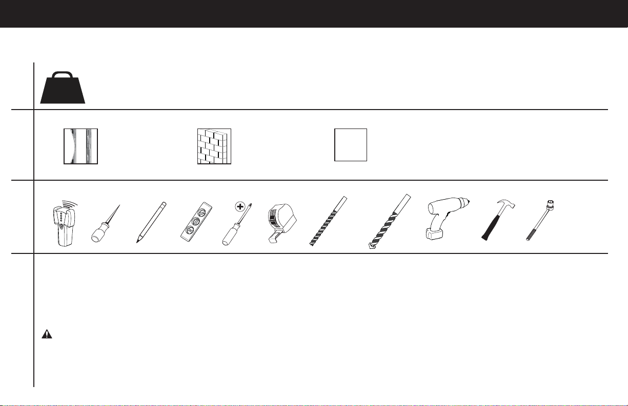
Before getting started, let’s make sure this mount is perfect for you!
Does your TV weigh more than 175 lb (79.3 kg) including accessories?
1
175 lb
(79.3 kg)
What is your wall made of?
No — Perfect!
Yes — This mount is NOT compatible. Visit MountFinder.Sanus.com or call 1-800-359-5520 (UK: 0800-056-2853) to fi nd a compatible mount.
2
Drywall with
wood studs
Perfect! Perfect! Call 1-800-359-5520 (UK: 0800-056-2853)
Do you have all of the tools needed?
Solid concrete or
concrete block
?
Unsure?
3
7/32 in.
(5.5 mm)
Wood
Ready to begin?
4
Please read through these instructions completely to be sure you’re comfortable with this easy install process. Also check your TV
owner’s manual to see if there are any special requirements for mounting your TV.
If you do not understand these instructions or have doubts about the safety of the installation, assembly or use of this product, contact
Customer Service at 1-800-359-5520 (UK: 0800-056-2853).
1/2 in.
(13 mm)
Concrete
1/2 in.
(13 mm)
CAUTION: Avoid potential personal injuries and property damage!
● This product is designed for use in wood stud, solid concrete, and concrete block walls - DO NOT install into drywall alone
● The wall must be capable of supporting fi ve times the weight of the TV and mount combined
● Do not use this product for any purpose not explicitly specifi ed by manufacturer
2
● Manufacturer is not responsible for damage or injury caused by incorrect assembly or use
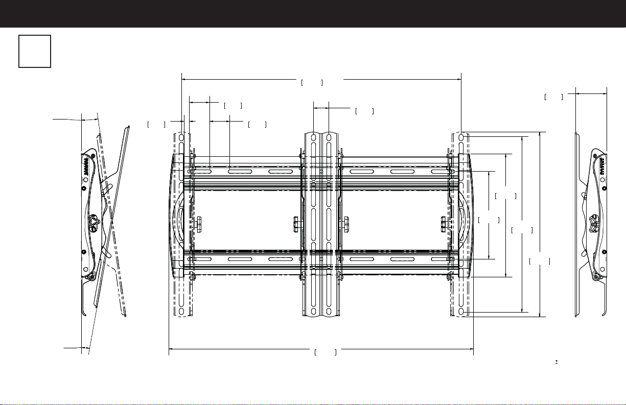
Dimensions
in.
[mm]
8°
MAX TILT UP
0.506
12.86
2.000
50.80
2.000
50.80
27.541
699.53
MAX.
1.503
38.18
MIN.
8.635
219.34
12.166
309.02
17.323
440.00
18.220
462.79
3.098
78.69
10°
MAX TILT DOWN
30.006
762.16
NOTE:
MAX. HEIGHT ADJUST
.5 IN.
3
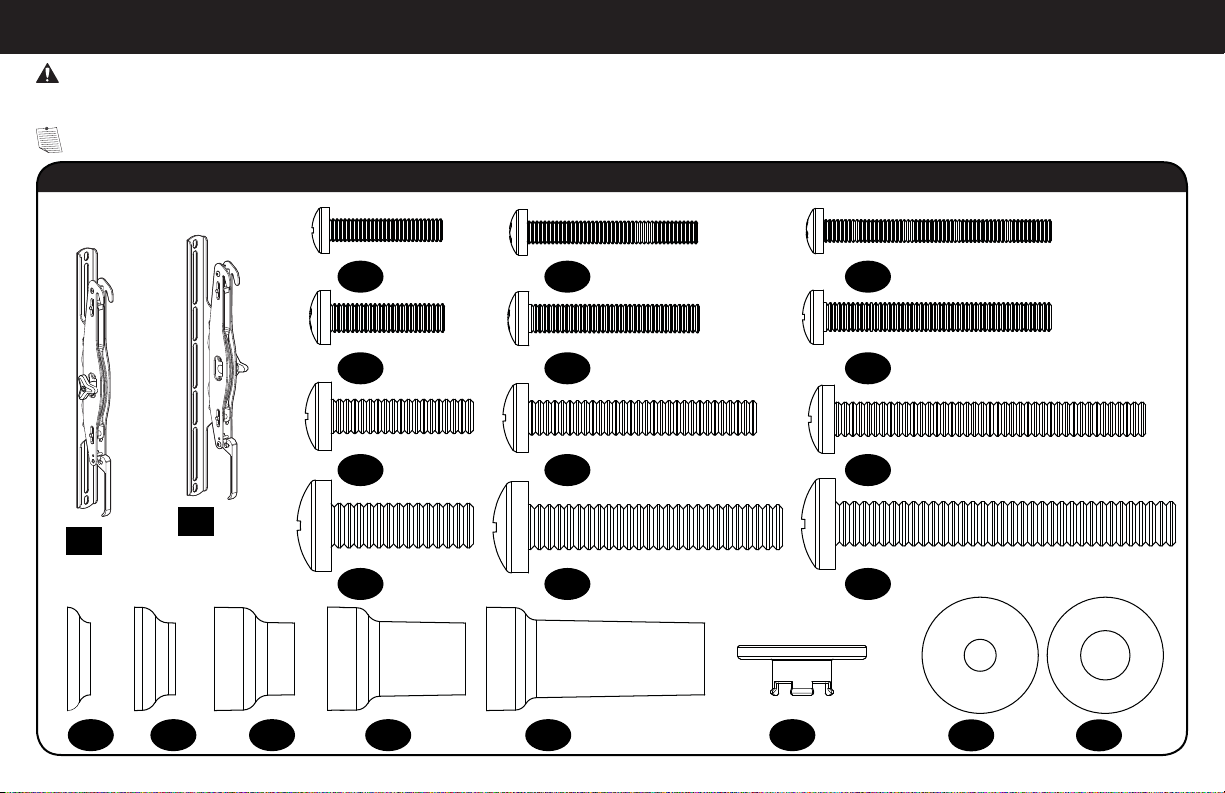
Parts and Hardware
WARNING: This product contains small items that could be a choking hazard if swallowed. Before starting assembly, verify all parts
are included and undamaged. If any parts are missing or damaged, do not return the damaged item to your dealer; contact Customer Service.
Never use damaged parts!
NOTE: Not all hardware included will be used.
Parts and Hardware for STEP 1
TV Brackets
M4 x 20mm
x4 x4 x4
03 07 11
TV Screws
M4 x 30mm
M4 x 40mm
M5 x 30mm
x4 x4 x4
04 08 12
M6 x 25mm
x4 x4 x4
05 09 13
x1
x1
01
Spacers
4mm 7mm 14mm 24mm 38mm
x4 x4 x4 x4 x4 x4
15 16 17 18 19 20
4
02
M8 x 25mm
x4 x4 x4
06 10 14
M6 x 40mm
M8 x 45mm
M5 x 40mm
M6 x 55mm
M8 x 60mm
Washers
M4 / M5 M6 / M8
x4 x4
21
22
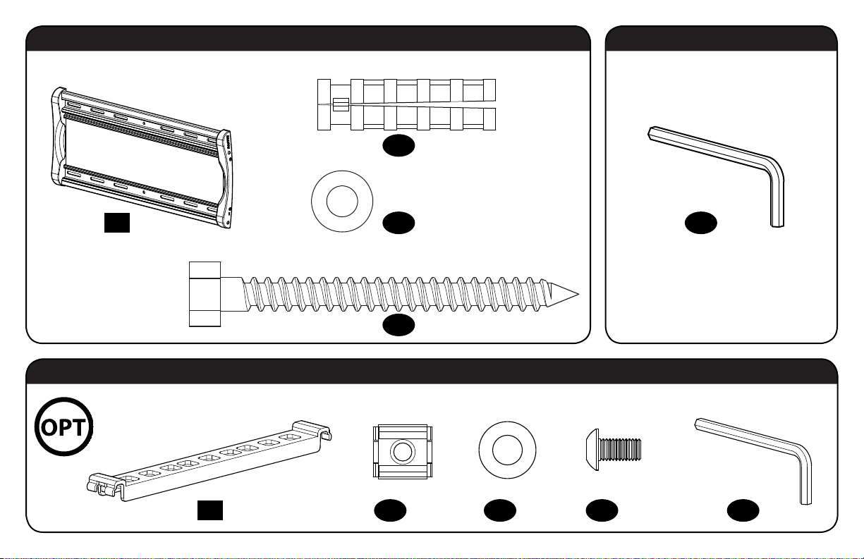
Parts and Hardware for STEP 2
Wall Plate
Anchors
x6
24
Washers
Hardware for Adjustments
Hex Key
3/16 in.
23
x1
5/16 in.
5/16 x 3 1/2 in.
x6
25
Lag Bolts
x6
26
Parts and Hardware for Optional Accessory Bracket Mounting
Bracket WashersCage Nut
10-32
28
x2
29
x4
30
x4
10-32 x 3/8 in.
x4
31
27
x1
Hex KeyScrew
1/8 in.
32
x1
5
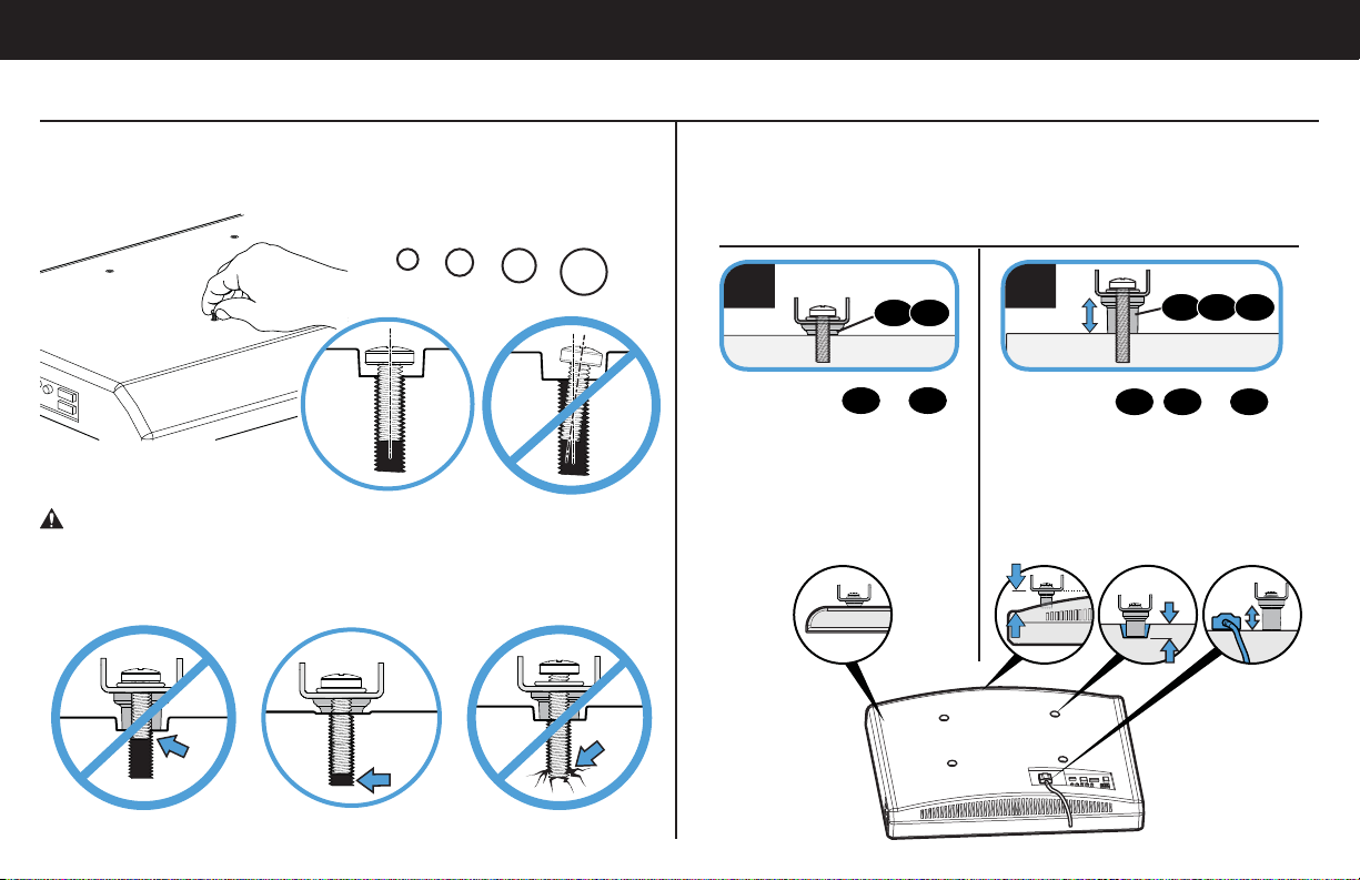
STEP 1 Attach Brackets to TV
1-1 Select TV Screws
Hand thread screws into the threaded inserts on the back of your TV
to determine which screw diameter (M4, M5, M6, or M8) to use.
M4 M6 M8M5
CAUTION: Verify adequate thread engagment of the screw
and spacer combination on your TV.
Too short will not hold the TV and too long will damage the TV.
1-2 Select TV Spacers
Spacers and screws are supplied to install your TV bracket.
Determine your preference for spacer configuration when
attaching your TV bracket.
a
15 16
or
16
Use spacers
if your TV has a flat back
AND you want your TV
closer to the wall.
15
b
Use spacers
to accommodate:
● Round/irregular back TVs
● TVs with inset mounting holes
● Extra space needed for cables
Round Back CablesInset HolesFlat Back
17
17 18 19
18
,
or
19
6
Too Short Correct Too Long
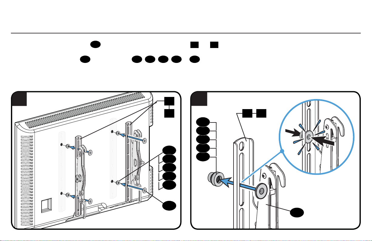
1-3 Attach Spacers to TV Brackets
1. Press the shoulder washers 20 through the openings of TV brackets
15
16
17
2. Snap shoulder washers 20 into the spacers
1
,
18
,
or 19 you selected in STEP 1-2.
,
01
02 0201
15
16
17
18
19
20
01
and 02 that line up with your TV hole pattern.
2
15
16
17
18
19
20
7
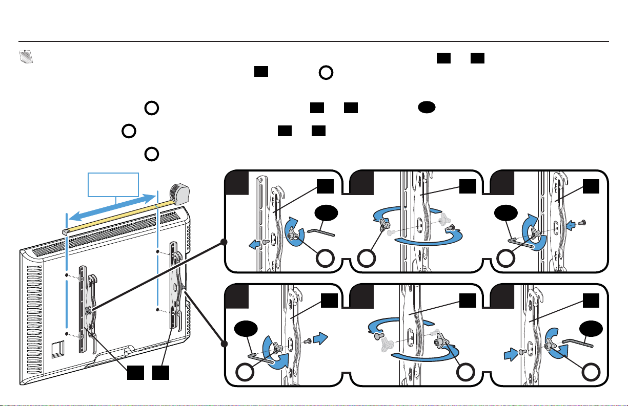
1-4 Prepare TV Brackets (ONLY For TV Hole Patterns Wider than 600mm)
NOTE: For TV's with hole patterns wider than 600 mm (≈23 5/8 in.), the placement of TV brackets
to fit your pattern and still allow hanging onto wall plate 23. The knobs
tension adjustments after installation.
1. Unscrew tilt tension knob
2. Flip tilt tension knob
3. Reattach tilt tension knob
> 600mm
≈
(
23 5/8 in.)
K
from the screw on both TV brackets
K
to the opposite side of TV bracket
onto the screw.
K
1 2 3
01
and 02.
need to be repositioned to the outside for accessability and tilt
K
01
and 02 using hex key
02 02 02
1 2 3
27
27.
01
and
02
must be reversed on your TV
2727
KKK
010101
27
02 01
8
K
K K

1-5 Attach TV Brackets
Center the TV brackets
IMPORTANT: Install with tilt tension knobs
Install using the screw and washer combination [a] or [b] you selected for your TV.
NOTE: Use washer 21 for screws 03, 04, 07, 08, 11 and 12.
Use washer 22 for screws 05, 06, 09, 10, 13 and 14.
01
and
02
over your TV hole pattern as shown, making sure the brackets are level with each other.
toward the outside.
K
01 02
K
Flat Back
a
151716
Round Back / Extra Space
b
07
212122
08 09 10 11
03 04 05
12 13
06
14
K
18 19
22
9
 Loading...