

Page 1

International Assembly Instructions for model JFA36
ENGLISH
ESPAÑOL FRANÇAIS ITALIANO Русский
Sanus Systems 2221 Hwy 36 West, Saint Paul, MN 55113 USA (6901-300106 <00>)
Customer Service: (800) 359-5520 • (651) 484-7988 • fax (651) 636-0367
Customer Service Europe: +31 - (0)40 26 68 619 • fax +31 - (0)40 26 68 615
See complementary Sanus products at www.sanus.com
中文
Page 2

Page 3

Assembly Instructions for Model: JFA36
Thank you for choosing the Java Furniture line from Sanus Systems.
Safety Warning: If you do not understand these directions, or have any doubts about the safety of the installation, please call a
qualified contractor or contact Sanus at 800.359.5520 or www.sanus.com. Check carefully to make sure that there are no missing
or defective parts. Our customer service representatives can quickly assist you with installation questions and missing or damaged
parts. Replacement parts for products purchased through authorized dealers will be shipped directly to you. Never use defective parts.
Improper installation may cause damage or serious injury. Do not use this product for any purpose that is not explicitly specified by
Sanus Systems. Sanus Systems can not be liable for damage or injury caused by incorrect mounting, incorrect assembly, or incorrect use.
Please call Sanus Systems before returning products to the point of purchase.
Required Tools: Phillips screw driver, hammer or mallet (optional)
Supplied Parts and Hardware: Some parts not shown as actual size*
(14) Cam Pin - b (18) Dowel - c
(14) Cam - a
ENGLISH
(8) M6 Bolt - d (8) Rubber Spacer - e (8) Aluminum Spacer - f
(4) Base Bolt - g (8) Carpet Glide - h (16) Back Panel Screw - i (1) Allen Key - j*
(12) Shelf Pin - k (12) Shelf Pin Screw - l (1) Door Latch - m (4) Latch Screw - n
Sanus Systems 2221 Hwy 36 West, Saint Paul, MN 55113 USA
Customer Service: 800.359.5520. See complementary Sanus products at www.sanus.com
Page 4
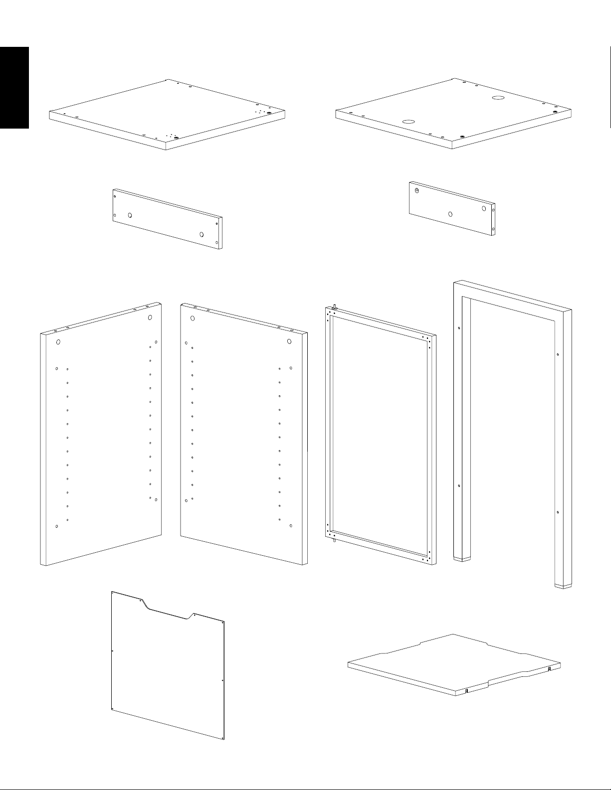
Parts:
ENGLISH
(1) Top - o (1) Bottom - p
(2) Main Base Rail - q (2) Side Base Rail - r
(1) Left Side Panel - s (1) Right Side Panel - t (1) Door - u (2) Leg - v
(3) Shelf - x
(2) Back Panel - w
Page 5

Step 1: Add Cam Pins and Dowels to Base
Thread a Cam Pin (b) into each threaded hole and insert a Dowel (c) into each adjacent hole in the Bottom (p). Tighten each with a
Phillips screw driver. See Diagram 1 for assistance.
Diagram 1 Detailed View
b
c
p
ENGLISH
Step 2: Add Side Panels
Orient the Side Panels (s,t) so the notch is facing the ground and the shelf holes are facing each other. Insert a Dowel (c) into each hole
(closest to the center in the bottom of each Side Panel). Insert a Base Bolt (g) through the Bottom (p) and into each Side Panel. Tighten
each Base Bolt with the Allen Key (j). See Diagram 2 for Assistance.
Diagram 2
t
s
c g
p
notch
Page 6
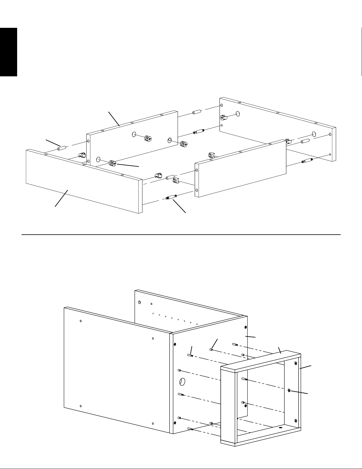
Step 3: Base Assembly
Insert 10 Cams (a), four Cam Pins (b) and four Dowels (c) into the Main Base Rail (q) and Side Base Rail (r). Tighten each Cam Pin
with a Phillips screw driver. Make sure the arrow on each Cam is pointed toward the closest hole. Press fit each rail together until a solid
rectangle is formed. Tighten each Cam that corresponds with a Cam Pin in a clockwise motion to secure the Rails together. See Diagram
3 for assistance.
ENGLISH
Diagram 3
r
c
a
q
b
Step 4: Add Base Assembly to Bottom
Align the assembled base frame so the holes line up with the Dowels (c) and Cam Pins (b) on the Bottom (p). Proceed to tighten all six
of the Cams (a) on the Rails (q,r) that correspond with the Cam Pins on the Bottom so the assembled base frame is secure. See Diagram
4 for Assistance.
Diagram 4
c p
b q
r
a
Page 7

Step 5: Add Carpet Glides
Gently tap the Carpet Glides (h) into each frame assembly. See Diagram 5 for Assistance.
Diagram 5 Detailed View
h
ENGLISH
Step 6: Add Door Latch
Attach the Door Latch (m) to the Top (o) with the four Latch Screws (n). Tighten each Latch Screw with a Phillips screw driver. See
Diagram 6 for assistance.
Diagram 6
Detailed View
o
m
n
Page 8

Step 7: Prepare Top
Insert a Cam Pin (b) into each threaded hole and insert a Dowel (c) into each adjacent hole in the Top (o). Tighten each Cam Pin with a
Phillips screw driver. See Diagram 7 for assistance.
Diagram 7
ENGLISH
Detailed View
c
b
o
Step 8: Add Door and Top
Gently position the cabinet assembly so it is up-right and resting on the base. Insert a Cam (a) into each Side Panel (s,t). Make sure the
arrow on each Cam points toward the appropriate Cam Pin in the Top (o). Insert the Door (u) into the base so the pivot side is opposite
from the Door Latch (m). Fit the Top onto the Side Panels so the Cam Pins correspond with the Cams and the Door is secured in the top.
Tighten each Cam in a clockwise motion. See the Diagrams below for assistance.
Detailed View View from Front View from Back
notch
pivot point
a
u
o
Page 9

Step 9: Add Legs
To add the Legs (v) first slide the Rubber Spacer (e) so it fits into the Aluminum Spacer (f). Take a M6 Bolt (d) and insert it through the
Side Panel (s,t), the Spacer Assembly and finally thread it into the Leg. Repeat this process for the remaining holes on each leg. Tighten
each M6 Bolt with the Allen Key (j). See Diagram 9 for assistance.
Diagram 9
f
v e
d
ENGLISH
Step 10: Install Shelves
Insert a Shelf Pin Screw (l) through a Shelf Pin (k) and into the desired hole in the Side Panel (s,t). Tighten with a Phillips screw driver.
Repeat process until all 12 Shelf Pins are installed. See the Detailed View of Diagram 10 for assistance.
Place each Shelf (x) in cabinet so they fit on top of the Shelf Pins. Press down firmly until it locks into place. See Diagram 10 for
assistance.
Detailed View
Diagram 10
x
l k
back of cabinet assembly
Page 10

Step 11: Add Back Panels
Insert a Back Panel Screw (i) through the Back Panel (w) and into the cabinet assembly in the locations shown in Diagram 11. Tighten
each Back Panel Screw with a Phillips screw driver. Repeat process for the other Back Panel.
Diagram 11
ENGLISH
i
w
Note: Sanus recommends placing components and completing all necessary wire and cable hook-ups before
attaching the Back Panels.
Complete Assembly
Sanus Systems 2221 Hwy 36 West, Saint Paul, MN 55113 USA
Customer Service: 800.359.5520. See complementary Sanus products at www.sanus.com
Page 11

Instrucciones de ensamblaje del modelo: JFA36
Gracias por elegir la línea de muebles Java de Sanus Systems.
Advertencia de seguridad: Si no entiende estas instrucciones o si tiene alguna duda con respecto a la seguridad de la instalación, llame
a un contratista cualificado o comuníquese con Sanus llamando al 800.359.5520 (en EE.UU.) o al 31 (0) 40 2668619 (en Europa). Puede
también visitar nuestro sitio web en www.sanus.com. Revise cuidadosamente los productos para asegurarse de que ninguna pieza falte ni
presente defectos. Nuestros representantes del servicio de atención al cliente le ofrecerán asistencia inmediata con cualquier duda sobre la
instalación o con respecto a piezas faltantes o dañadas. Las piezas de repuesto para los productos comprados a través de un distribuidor
autorizado se enviarán directamente a usted. Nunca use piezas defectuosas. La instalación incorrecta podría ocasionar daños o lesiones
graves. No utilice este producto para fines no explícitamente especificados por Sanus Systems. Sanus Systems no será responsable por daños
ni lesiones debidos al montaje, ensamblaje o uso incorrectos. Llame a Sanus Systems antes de devolver los productos al punto de compra.
Herramientas necesarias: Destornillador Phillips, martillo o mazo (optativo)
Piezas y tornillería suministradas: Algunas piezas no se muestran en tamaño real*
(14) Leva - a (14) Pasador de leva - b (18) Espiga - c
ESPAÑOL
(8) Perno M6 - d (8) Espaciador de goma - e (8) Espaciador de aluminio - f
(4) Perno de base - g (8) Deslizador para alfombra - h (16) Tornillo de panel trasero - i (1) Llave allen - j*
(12) Pasador de apoyo de repisa - k (12) Tornillo de pasador de (1) Seguro de puerta - m (4) Tornillo de seguro
apoyo repisa - l de puerta - n
Sanus Systems 2221 Hwy 36 West, Saint Paul, MN 55113 USA
Servicio de atención al cliente: 800.359.5520. Vea los productos complementarios de Sanus en el sitio www.sanus.com
Page 12

Piezas:
(1) Plancha superior - o (1) Plancha inferior - p
ESPAÑOL
(2) Tabla principal de base - q (2) Tabla lateral de base - r
(1) Panel lateral izquierdo - s (1) Panel lateral derecho - t (1) Puerta - u (2) Pata - v
(3) Repisa - x
(2) Panel trasero - w
Page 13

Paso 1: Adición de los pasadores de leva y espigas a la base
Enrosque un pasador de leva (b) en cada agujero roscado e inserte una espiga (c) en cada agujero adyacente de la plancha inferior (p).
Apriételos todos con un destornillador Phillips. Vea el diagrama 1 como ayuda.
Diagrama 1 Vista detallada
b
c
p
ESPAÑOL
Paso 2: Adición de los paneles laterales
Oriente los paneles laterales (s,t) de forma tal que la muesca quede hacia el piso y los agujeros queden frente a frente. Inserte una espiga (c)
en cada agujero (el más cercano al centro en la parte inferior de cada panel lateral). Inserte un perno de base (g) a través de la plancha
inferior (p) y luego en cada panel lateral. Apriete cada perno de base con una llave allen (j). Vea el diagrama 2 como ayuda.
Diagrama 2
t
s
c g
p
muesca
Page 14

Paso 3: Ensamblaje de la base
Inserte 10 levas (a), 4 pasadores de leva (b) y cuatro espigas (c) en las tablas principales (q) y laterales (r) de la base. Apriete todos los
pasadores de leva con un destornillador Phillips. Verifique que la flecha de cada leva quede apuntando hacia el agujero más cercano. Una
las tablas de la base encajándolas a presión hasta formar un rectángulo firme. Apriete cada leva que corresponda con un pasador girando
en sentido horario para fijar las tablas entre sí. Vea el diagrama 3 como ayuda.
Diagrama 3
r
ESPAÑOL
c
a
q
b
Paso 4: Adición de la base a la plancha inferior
Oriente la base armada de manera que los agujeros queden alineados con las espigas (c) y los pasadores de leva (b) de la plancha inferior (p)
Proceda a ajustar las seis levas (a) de las tablas (q,r) que concuerdan con los pasadores de leva de la plancha inferior hasta que el bastidor
de la base quede firme. Vea el diagrama 4 como ayuda.
Diagrama 4
c p
b q
r
.
a
Page 15

Paso 5: Adición de los deslizadores para alfombra
Inserte los deslizadores para alfombra (h) en la base golpeándolos suavemente. Vea el diagrama 5 como ayuda.
Diagrama 5 Vista detallada
h
ESPAÑOL
Paso 6: Adición del seguro de la puerta
Acople el seguro de la puerta (m) a la plancha superior (o) con los cuatro tornillos correspondientes (n). Ajuste todos los tornillos del
seguro con un destornillador Phillips. Vea el diagrama 6 como ayuda.
Diagrama 6
Vista detallada
o
m
n
Page 16

Paso 7: Preparación de la plancha superior
Inserte un pasador de leva (b) en cada agujero roscado y una espiga (c) en cada agujero adyacente de la plancha superior (o). Ajuste todos
los pasadores de leva con un destornillador Phillips. Vea el diagrama 7 como ayuda.
Diagrama 7
Vista detallada
c
ESPAÑOL
b
o
Paso 8: Adición de la puerta y la plancha superior
Con mucho cuidado, ponga el gabinete armado en posición vertical con la base sobre el suelo. Inserte una leva (a) en cada panel lateral
(s,t).
Verifique que la flecha de cada leva quede apuntando hacia el pasador de leva correspondiente de la plancha superior (o). Inserte la
puerta (u) en la base de manera que el pivote quede del lado opuesto al seguro de la puerta (m). Coloque la plancha superior sobre los
paneles laterales de manera que los pasadores de leva concuerden con las levas y la puerta quede asegurada a la plancha superior. Ajuste
cada pasador de leva con un giro en sentido horario. Vea los diagramas que siguen como ayuda.
Vista detallada Vista desde la parte anterior Vista desde la parte posterior
muesca
punto de pivote
a
u
o
Page 17

Paso 9: Adición de las patas
Para agregar las patas (v), deslice primero el espaciador de goma (e) para que encaje en el espaciador de aluminio (f). Tome luego un
perno M6 (d), insértelo a través del panel lateral (s,t) y en el espaciador, y enrósquelo en la pata. Repita el proceso para los agujeros
restantes de cada pata. Apriete todos los pernos M6 con la llave allen (j). Vea el diagrama 9 como ayuda.
Diagrama 9
f
v e
d
ESPAÑOL
Paso 10: Colocación de las repisas
Inserte un tornillo (l) por un pasador de apoyo de repisa (k) y luego en el agujero deseado del panel lateral (s,t). Apriete con un destornillador
Phillips. Repita el proceso hasta haber colocado los 12 pasadores de apoyo de repisa. Consulte la vista detallada del diagrama 10 como ayuda.
Coloque las repisas (x) en el gabinete de manera que calcen sobre los pasadores de apoyo. Presione firmemente cada repisa para que
encaje en su lugar. Vea el diagrama 10 como ayuda.
Vista detallada
Diagrama 10
x
l k
Parte posterior del gabinete
Page 18

Paso 11: Adición de los paneles traseros
Inserte un tornillo de panel trasero (i) a través de un panel trasero (w) y luego en el gabinete en los lugares que se muestran en el diagrama 11
Apriete cada tornillo del panel trasero con un destornillador Phillips. Repita el proceso para el otro panel trasero.
Diagrama 11
ESPAÑOL
i
w
.
Nota: Sanus recomienda colocar los componentes y llevar a cabo todas las conexiones de cables antes de acoplar
el panel trasero.
Ensamblaje terminado
Sanus Systems 2221 Hwy 36 West, Saint Paul, MN 55113 USA
Servicio de atención al cliente: 800.359.5520. Vea los productos complementarios de Sanus en el sitio www.sanus.com
Page 19

Instructions de montage pour le modèle : JFA36
Nous vous remercions d’avoir choisi la gamme de meubles Java de Sanus Systems.
Avertissements relatifs à la sécurité : si vous ne comprenez pas ces instructions ou si vous avez un doute quant à la sécurité
de cette installation, veuillez faire appel à un technicien qualifié ou communiquez avec Sanus en composant le 1-800-359-5520
(aux É.-U.), ou le 31 (0) 40 2668619 (pour l’Europe). Vous pouvez également visiter notre site web au www.sanus.com. Vérifiez
soigneusement qu’aucune pièce n’est manquante ou défectueuse. Les représentants de notre service à la clientèle peuvent répondre
rapidement à toute question concernant l’installation ou des pièces manquantes ou endommagées. Les pièces de rechange de produits
achetés auprès de distributeurs agréés vous seront livrées directement. N’utilisez jamais de pièces défectueuses. Une installation incorrecte
peut entraîner des dommages ou des blessures graves. Ce produit ne doit être utilisé que pour des usages explicitement spécifiés par
Sanus Systems. Sanus Systems ne pourra être tenu responsable de dommages ou de blessures dus à un montage incorrect, un assemblage
incorrect ou un usage incorrect. Veuillez contacter Sanus Systems avant de renvoyer des produits au point de vente.
Outils nécessaires : tournevis cruciforme, marteau ou maillet (facultatif)
Pièces et matériel fournis : Certaines pièces ne sont pas illustrées grandeur réelle*
(14) Axe de came - b (18) Goujon - c
(14) Came - a
(8) Vis M6 - d (8) Entretoise en caoutchouc - e (8) Entretoise en aluminium - f
FRANÇAIS
(4) Vis pour base - g (8) Coussin de glissement - h (16) Vis pour panneau arrière - i (1) Clé Allen - j*
(12) Cheville d’étagère - k (12) Vis pour cheville d’étagère - l (1) Loquet - m (4) Vis de loquet - n
Sanus Systems 2221 Hwy 36 West, Saint Paul, MN 55113 USA
Service à la clientèle : 800.359.5520. Pour les produits Sanus complémentaires, visitez le site www.sanus.com
Page 20

Pièces :
(1) Panneau supérieur - o (1) Panneau inférieur - p
(2) Rail pour base principal - q (2) Rail pour base latéral - r
FRANÇAIS
(1) Panneau gauche - s (1) Panneau droit - t (1) Porte - u (2) Patte - v
(3) Étagère - x
(2) Panneau arrière - w
Page 21

Étape 1 : Montage des axes de came et des goujons sur la base
Vissez un axe de came (b) dans chaque trou fileté et insérez un goujon (c) dans chaque trou adjacent du panneau inférieur (p). Serrez-les
tous avec un tournevis cruciforme. Reportez-vous au schéma 1 si nécessaire.
Schéma 1 Vue détaillée
b
c
p
FRANÇAIS
Étape 2 : Montage des panneaux latéraux
Orientez les panneaux latéraux (s, t) de manière que l’encoche soit dirigée vers le bas et que les trous pour étagères soient en face les
uns des autres. Insérez un goujon (c) dans chaque trou (les plus proches du centre dans la partie inférieure de chaque panneau latéral).
Introduisez une vis pour base (g) dans le panneau inférieur (p) et dans chaque panneau latéral. Serrez toutes les vis pour base à l’aide de
la clé Allen (j). Reportez-vous au schéma 2 si nécessaire.
Schéma 2
t
s
c g
p
encoche
Page 22

Étape 3 : Montage de la base
Insérez 10 cames (a), quatre axes de came (b) et quatre goujons (c) dans le rail pour base principal (q) et le rail pour base latéral (r).
Serrez tous les axes de came à l’aide d’un tournevis cruciforme. Veillez à ce que la flèche sur chaque came pointe vers le trou le plus
proche. Enfoncez chaque rail l’un dans l’autre jusqu’à former un rectangle solide. Serrez toutes les cames correspondant aux axes de
came en les tournant dans le sens horaire afin de fixer les rails les uns aux autres. Reportez-vous au schéma 3 s’il le faut.
Schéma 3
r
c
a
q
b
FRANÇAIS
Étape 4 : Montage de la base sur le panneau inférieur
Alignez le cadre de base assemblé de manière que ses trous soient alignés sur les goujons (c) et les axes de came (b) du panneau inférieur
(p). Serrez les six cames (a) sur les rails (q, r) correspondant aux axes de came du panneau inférieur de manière que le cadre de base
assemblé soit solidement fixé. Reportez-vous au schéma 4 s’il le faut.
Schéma 4
c p
b q
r
a
Page 23

Étape 5 : Pose des coussins de glissement
Tapotez doucement sur les coussins de glissement (h) pour les enfoncer dans chaque cadre assemblé. Reportez-vous au schéma 5 si
nécessaire.
Schéma 5 Vue détaillée
h
FRANÇAIS
Étape 6 : Montage du loquet
Fixez le loquet (m) sur le panneau supérieur (o) à l’aide des quatre vis de loquet (n). Serrez toutes les vis à l’aide d’un tournevis
cruciforme. Reportez-vous au schéma 6 si nécessaire.
Schéma 6
Vue détaillée
o
m
n
Page 24

Étape 7 : Préparation du panneau supérieur
Insérez un axe de came (b) dans chaque trou fileté et introduisez un goujon (c) dans chaque trou adjacent du panneau supérieur (o).
Serrez tous les axes de came à l’aide d’un tournevis cruciforme. Reportez-vous au schéma 7 si nécessaire.
Schéma 7
Vue détaillée
c
b
o
FRANÇAIS
Étape 8 : Montage de la porte et du panneau supérieur
Relevez doucement l’armoire de manière à ce qu’elle repose sur sa base, en position verticale. Insérez une came (a) dans chaque panneau
latéral (s, t). Veillez à ce que la flèche sur chaque came pointe vers l’axe de came correspondante dans le panneau supérieur (o). Insérez
la porte (u) dans la base de manière que le côté avec pivot soit en face du loquet (m). Ajustez le panneau supérieur aux panneaux latéraux
de manière que les axes de came correspondent aux cames et que la porte soit solidement fixée en partie supérieure. Serrez toutes les
cames en les tournant dans le sens horaire. Reportez-vous aux schémas ci-dessous s’il le faut.
Vue détaillée Vue de l’avant Vue de l’arrière
encoche
point de
pivotement
a
u
o
Page 25

Étape 9 : Montage des pattes
Pour monter les pattes (v), faites d’abord glisser l’entretoise en caoutchouc (e) pour l’ajuster sur l’entretoise en aluminium (f). Prenez ensuite
une vis M6 (d) et insérez-la dans le panneau latéral (s, t) et l’ensemble d’entretoises, puis vissez-la dans la patte. Répétez cette procédure
pour les autres trous de chaque patte. Serrez toutes les vis M6 à l’aide de la clé Allen (j). Reportez-vous au schéma 9 si nécessaire.
Schéma 9
f
v e
d
FRANÇAIS
Étape 10 : Installation des étagères
Insérez une vis pour cheville d’étagère (l) dans une cheville d’étagère (k) et dans le trou souhaité du panneau latéral (s, t). Serrez à l’aide
d’un tournevis cruciforme. Répétez la procédure jusqu’à ce que les 12 chevilles d’étagère soient toutes installées. Reportez-vous à la
vue détaillée du schéma 10 s’il le faut.
Placez chaque étagère (x) dans l’armoire de manière à ce qu’elles reposent correctement sur les chevilles. Appuyez fermement sur
chacune des étagères pour les fixer solidement en place. Reportez-vous au schéma 10 si nécessaire.
Vue détaillée
Schéma 10
x
l k
arrière de l’armoire
Page 26

Étape 11 : Montage des panneaux arrière
Insérez une vis pour panneau arrière (i) dans le panneau arrière (w) et dans l’armoire aux emplacements indiqués sur le schéma 11.
Serrez toutes les vis sur le panneau arrière à l’aide d’un tournevis cruciforme. Répétez la procédure pour l’autre panneau arrière.
Schéma 11
i
w
FRANÇAIS
Remarque : Sanus recommande de mettre en place tous les composants et d’effectuer tous les raccordements de
ls et de câbles avant de xer les panneaux arrière.
Montage terminé
Sanus Systems 2221 Hwy 36 West, Saint Paul, MN 55113 USA
Service à la clientèle : 800.359.5520. Pour les produits Sanus complémentaires, visitez le site www.sanus.com
 Loading...