

Page 1
FTVS
1
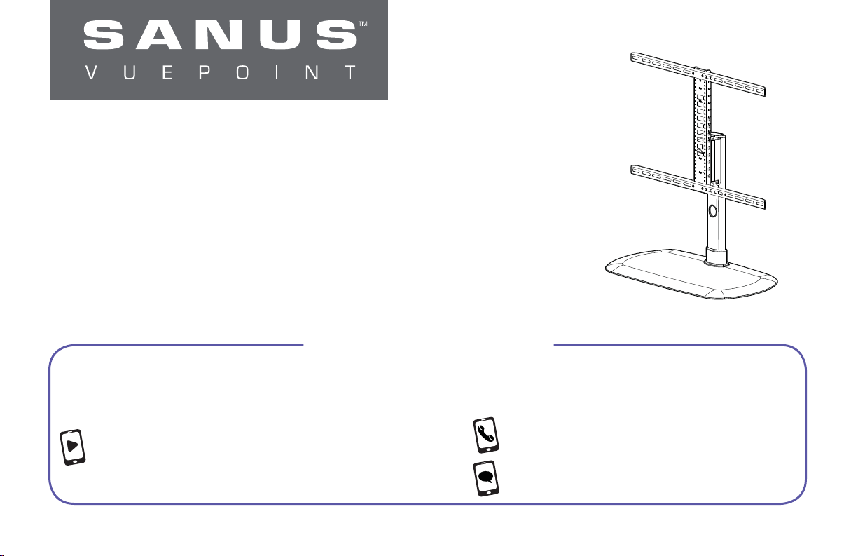
Swivel TV Base
INSTRUCTION MANUAL
WE’RE HERE TO HELP
Want to watch a video that shows
how easy this assembly will be?
Watch it now at: SANUS.com/2612
Our US-based install experts
are standing by to help.
Call us at: 888-333-9952
Or, chat at: SANUS.com/chatSV
Page 2
IMPORTANT SAFETY INSTRUCTIONS – PLEASE READ ENTIRE MANUAL PRIOR TO USE – SAVE THESE INSTRUCTIONS
Before getting started, let’s make sure this mount is perfect for you!
Does your TV
(including accessories)
1
weigh more than
60 lbs. (27.2 kg)?
Do you have
2
the tools needed?
Ready to begin?
3
2
60 lbs.
(27.2 kg)
Please read through these instructions completely to be sure you’re comfortable with this easy install process. Also check
your TV owner’s manual to see if there are any special requirements for mounting your TV.
If you do not understand these instructions or have doubts about the safety of the installation, assembly or use of this
product, contact Customer Service.
CAUTION: Avoid potential personal injuries and property damage! Manufacturer is not responsible for damage or injury
caused by incorrect assembly or use.
WARNING: Exceeding the weight capacity can result in serious personal injury or damage to equipment! It is the
installer’s responsibility to make sure the combined weight of the display (including accessories) does not exceed 60 lbs
(27.2 kg). Use with heavier televisions may result in instability causing tip over resulting in death or serious injury!
WARNING: Use this mounting system only for its intended use as described in these instructions. Do not use
attachments not recommended by the manufacturer.
WARNING: Death or serious injury may occur when children climb on audio and/or video equipment furniture.
A remote control or toys placed on the furnishing may encourage a child to climb on the furnishing and as a result the
furnishing may tip over onto the child.
WARNING: Relocating audio and/or video equipment to furniture not specifi cally designed to support audio and/or
video equipment may result in death or serious injury due to the furnishing collapsing or overturning onto a child.
NOTE: The FTVS1 can support screen sizes up to a maximum of 60" diagonal.
NOTE: The FTVS1 has no user serviceable parts.
No
—
Perfect!
Yes
—
This mount is NOT compatible. Visit vuepoint.sanus.com or call 1-888-333-9952
to fi nd a compatible mount.
Level
Screwdriver
Para Español ver página 14
Page 3
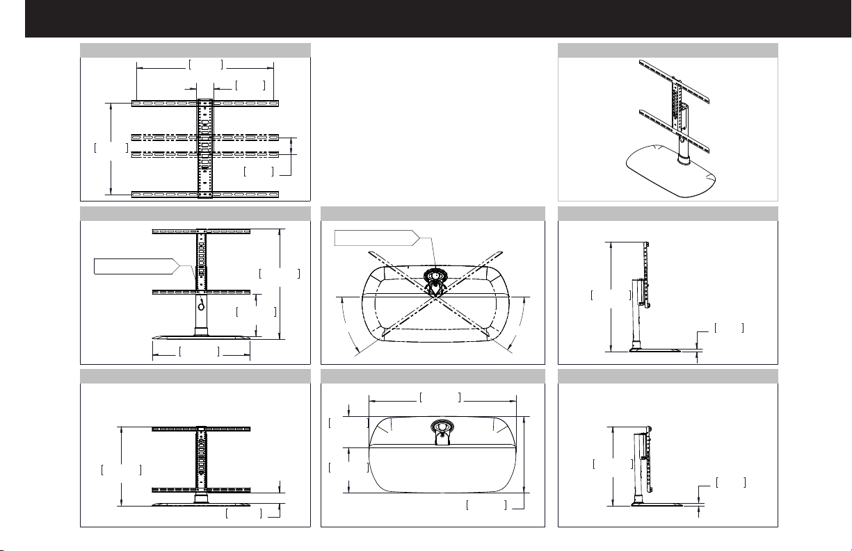
Dimensions
TV INTERFACE
600mm
23.62in
400mm
15.75in
75mm
2.95in
75mm
2.95in
FRONT VIEW - MAXIMUM HEIGHT
CABLE MANAGMENT
THROUGH TUBE
278.1mm
10.95in
644.2mm
25.36in
FRONT VIEW - MINIMUM HEIGHT
726.4mm
28.60in
3-D
TOP VIEW - SWIVEL
CABLE MANAGMENT
THROUGH TUBE
35deg
35deg
TOP VIEW - MAX DIMENSIONS
644.2mm
137.6mm
5.42in
25.36in
SIDE VIEW - MAXIMUM HEIGHT
722.6mm
28.45in
16mm
.63in
SIDE VIEW - MINIMUM HEIGHT
522.6mm
20.58in
198.9mm
71.7mm
2.82in
7.83in
335.3mm
13.20in
522.6mm
20.58in
16mm
.63in
3
Page 4
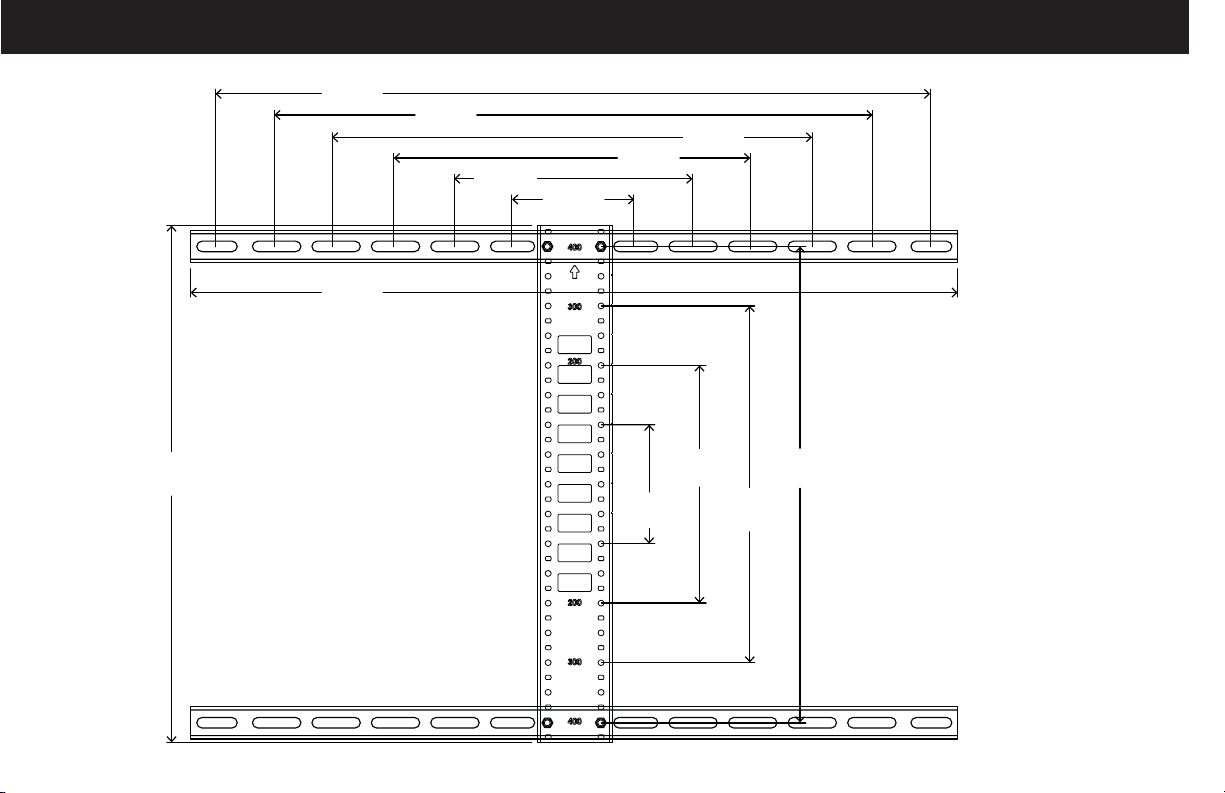
Dimensions - TV Interface
23.62 in.
(600 mm)
25.36 in.
(644.16 mm)
19.69 in.
(500 mm)
7.87 in.
(200 mm)
4.00 in.
(100 mm)
11.81 in.
(300 mm)
15.75 in.
(400 mm)
17.13 in.
(435 mm)
7.87 in.
(200 mm)
4.00 in.
(100 mm)
15.75 in.
(400 mm)
11.75 in.
(300 mm)
4
Page 5
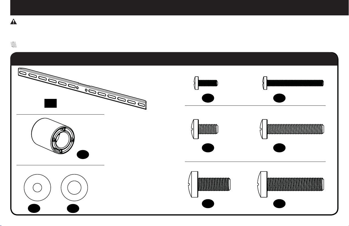
M8 x 35mm
M
6
/
M
8
M
4
M4 x 12mm
M6 x 12mm M6 x 35mm
M4 x 35mm
M8 x 20mm
Supplied Parts and Hardware
WARNING: This product contains small items that could be a choking hazard if swallowed.
Before starting assembly, verify all parts are included and undamaged. If any parts are missing or damaged, do not return the damaged item to
your dealer; contact Customer Service. Never use damaged parts!
NOTE: Not all hardware included will be used.
STEP 1 Parts and Hardware
TV Screws
M4
TV Bracket
01 x2
Spacers
22 mm
Washers
03 x4
04 x4
02 x4
M6
M8
05 x4
06 x4
07 x4
08 x4
09 x4
10 x4
5
Page 6
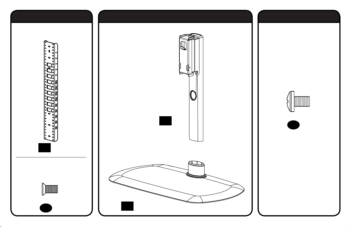
10-32 x 3/8 in.
1/4-20 x 3/8 in.
STEP 2 Parts and Hardware STEP 3 Parts and Hardware STEP 4 Hardware
Vertical Height Adjustment
Bracket
Lock Screws
Post
13 x1
15 x4
11 x1
Interface Screws
(Vertical Height
Adjustment Bracket)
Base
12 x4
6
14 x1
Page 7
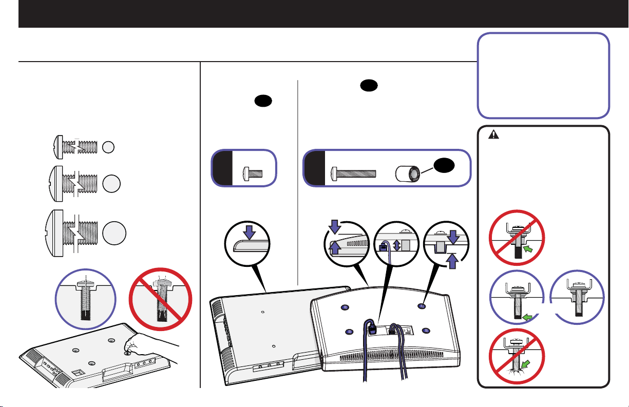
STEP 1 Attach TV Brackets to TV
1.1 Select TV Screw Diameter
Test the three TV screw diameters (M4,
M6, or M8) in the threaded inserts on
the back of your TV to determine which
screw diameter fits your TV.
M4
M6
M8
1.2 Select TV Screw Length
: For flat-back TVs,
a
no spacers
required.
02
a
FLAT BACK ROUND BACK CABLES INSET HOLES
: Spacers
b
● Round (irregular) back TVs
● Extra space needed (for cables
b
02
supplied for:
or inset mounting holes)
02
Standard configurations
are shown. For special
applications, or if you
are uncertain about your
hardware selection, contact
Customer Service
CAUTION:
Verify adequate thread
engagement with your screw/
washer/spacer combination
AND TV bracket.
- Too short will not hold the TV.
- Too long will damage the TV.
Too Short
Correct
Too Long
7
Page 8
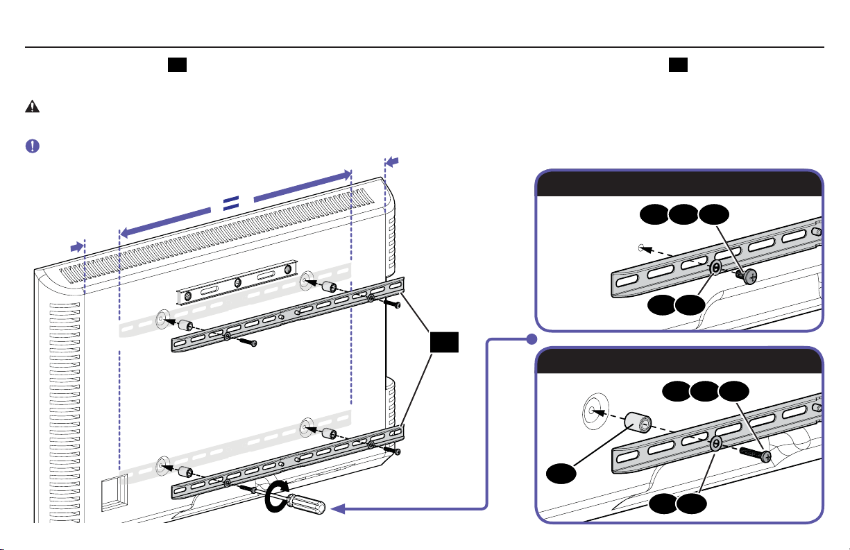
1.3 Attach Horizontal Brackets
Position your TV brackets 01 over your TV hole pattern - making sure the brackets are centered. Secure TV brackets 01 using your selection for
screw/washer (a: Flat Back) or screw/washer/spacer (b: Round Back / Extra Space).
CAUTION: Avoid potential personal injuries and property damage! DO NOT use power tools for this step. Tighten the screws only enough
to secure the TV bracket to the TV. DO NOT overtighten the screws.
IMPORTANT: Ensure TV brackets are securely fastened before moving on to the next step.
a: Flat Back
05 06 07
03
04
01
b: Round Back / Extra Space
08 09 10
02
03
04
8
Page 9
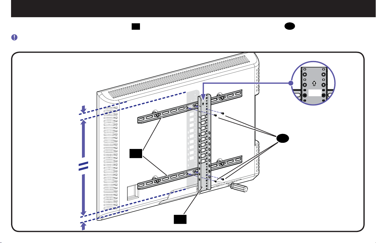
STEP 2 Attach Vertical Bracket
Make sure the vertical height adjustment bracket 11 is CENTERED on the TV and secure using interface screws 12.
IMPORTANT: Ensure all brackets are securely fastened before moving on to the next step.
12
01
UP
11
9
Page 10
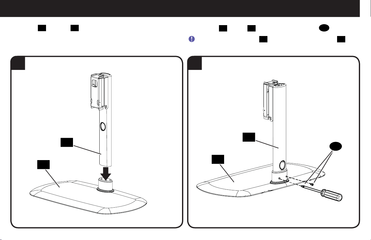
STEP 3 Attach Post to Base
Insert post 13 into base 14.
1 2
13
14
Secure post 13 to base 14 with the two lock screws 15.
IMPORTANT: Ensure post 13 is securely fastened to base 14
before moving on to the next step.
13
15
14
10
Page 11
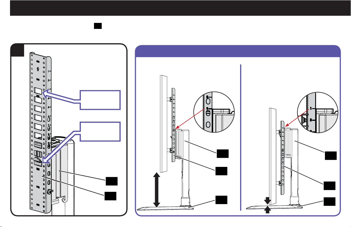
STEP 4 Attach TV to Post
Determine the height from the base 14 that you
would like your TV to hang.
1
Lowest
TV Position
Highest
TV Position
13
11
Examples
Highest Position
13
11
14
Lowest Position
13
11
14
11
Page 12
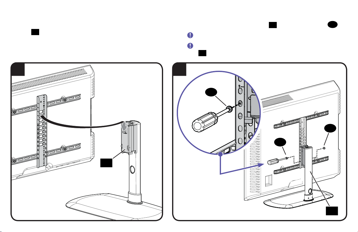
Hang the TV/bracket assembly (at your desired height) onto
the post 13.
2 3
13
Secure the TV/bracket assembly to post 13 with two lock screws 15.
IMPORTANT: Keep the base clear while installing TV.
IMPORTANT: Ensure TV/bracket assembly is securely fastened to
post 13 before moving on to the next step.
15
15
15
13
12
Page 13
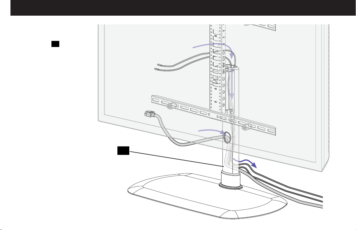
Cable Management
Route your cables through
either the front or top
opening of post 13, then
out the back.
13
13
Page 14
ESPAÑOL
LEA EL MANUAL COMPLETO ANTES DE UTILIZAR ESTE PRODUCTO – CONSERVE ESTAS INSTRUCCIONES
INSTRUCCIONES DE SEGURIDAD IMPORTANTES
Antes de comenzar, verifi quemos si este soporte es el adecuado para usted
¿Su televisor (incluidos los
1
accesorios)
27,2 kg (60 lbs)?
¿Dispone de las
2
herramientas que necesita?
pesa más de
27,2 kg
(60 lb)
No. ¡Perfecto!
Sí. Este soporte NO es compatible. Visite vuepoint.sanus.com o llame al 1-888-333-9952
para encontrar un soporte compatible.
Nivel
Destornillador
¿Listo para comenzar?
3
PRECAUCIÓN: ¡Evite posibles lesiones personales y daños materiales! El fabricante no se responsabiliza de ningún daño o lesión resultante del montaje incorrecto o
del uso indebido.
ADVERTENCIA: exceder la capacidad máxima de peso podría causar lesiones graves o daños al equipo. Es responsabilidad del instalador asegurarse de queel peso combinado
de la pantalla (incluidos los accesorios) no supere los 27,2 kg (60 lbs). Utilizarlo con televisores más pesados podría provocar caídas y causar lesiones graves o incluso la muerte.
ADVERTENCIA: utilice el soporte únicamente para el fi n diseñado y de acuerdo con estas instrucciones. No utilice conexiones que no estén recomendadas por
el fabricante.
ADVERTENCIA: que los niños trepen por el mobiliario de audio y/o video podría provocar lesiones graves o incluso la muerte. Situar el control remoto o juguetes
sobre el mobiliario puede incitar a los niños a trepar por el mobiliario, lo que puede provocar caídas.
ADVERTENCIA: trasladar equipos de audio y/o video a mobiliario que no está específi camente diseñado para soportarlos puede provocar que la estructura vuelque
o se caiga causando lesiones graves o incluso la muerte.
NOTA: el FTVS1 puede soportar televisores de un tamaño máximo en diagonal de 60 pulgadas (153 cm).
NOTA: el FTVS1 no contiene piezas que el usuario pueda reparar.
Lea estas instrucciones en su totalidad para sentirse seguro y cómodo con este fácil proceso de instalación. Consulte igualmente el
manual del usuario de su televisor para saber si existe algún requisito especial para instalar su televisor en la pared.
Si no entiende las instrucciones o si tiene dudas acerca de la seguridad de la instalación, del ensamblaje o del uso del producto,
póngase en contacto con el Servicio de atención al cliente.
Dimensiones PÁGINA 3
Piezas y elementos de sujeción suministrados PÁGINA 5
ADVERTENCIA: este producto contiene piezas pequeñas que, en caso de ser tragadas, podrían producir asfixia. Antes de iniciar el ensamblaje,
compruebe que todas las piezas estén incluidas y en buenas condiciones. Si faltan piezas o alguna está dañada, no devuelva el artículo al distribuidor.
Póngase en contacto con el servicio de atención al cliente. Nunca utilice piezas deterioradas.
NOTA: no todos los elementos de sujeción incluidos deberán utilizarse.
14
Page 15
PASO 1 Fije los soportes al televisor PÁGINA 7
ESPAÑOL
1.1 Seleccione el diámetro de los tornillos para el televisor
Pruebe los tres diámetros de tornillo del televisor (
para determinar cuál es el diámetro de tornillo adecuado para su televisor.
M4, M6 y M8) en los encastres enroscados de la parte trasera del televisor
1.2 Seleccione la longitud de los tornillos para el televisor
a: Para los televisores con la parte trasera plana, no se requieren separadores
b: Separadores
adicional (para cables u orificios de montaje intercalados).
Se ilustran las configuraciones estándar. Si desea información sobre aplicaciones especiales o si tiene dudas sobre la selección de piezas, póngase
en contacto con el servicio de atención al cliente.
suministrados para: • Televisores con la parte trasera redondeada (irregulares). • Casos en los que se necesita un espacio
02
02
.
PRECAUCIÓN: verifique el enrosque adecuado de la combinación tornillo/arandela/separador Y el soporte del televisor.
— Si es demasiado corto, no sostendrá el televisor. — Si es demasiado largo, dañará el televisor.
PASO 2 Fije el soporte vertical PÁGINA 9
Asegúrese de que el soporte vertical de ajuste de altura
IMPORTANTE: asegúrese de que todos los soportes estén asegurados antes de continuar con el próximo paso.
11
esté CENTRADO en el televisor y fíjelo con los tornillos de acoplamiento 12.
PASO 3 Fije el poste a la base PÁGINA 10
13
1. Inserte el poste
2. Fije el poste 13 a la base 14 con los dos tornillos de bloqueo 15.
IMPORTANTE: asegúrese de que el poste 13 esté firmemente sujeto a la base 14 antes de continuar con el paso siguiente.
en la base 14.
PASO 4 Fije el televisor al poste PÁGINA 11
14
1. Determine a qué altura de la base
2. Cuelgue el conjunto de televisor y soporte (a la altura que desee) en el poste 13.
3. Fije el conjunto de televisor y soporte al poste 13 con los dos tornillos de bloqueo 15.
IMPORTANTE: mantenga la base despejada mientras instala el televisor.
IMPORTANTE: asegúrese de que el televisor/conjunto del soporte esté fijado de forma segura al poste 13 antes de continuar con el paso siguiente.
desea colgar su televisor.
Gestión de cables PÁGINA 13
13
Pase los cables a través de la parte frontal o la parte superior del poste
y sáquelos por la parte trasera.
15
Page 16
Thank you for choosing Sanus VuePoint! Please take a moment to let us know how we did:
Find us on Facebook: SANUS Follow us on Twitter @sanussystems
Milestone AV Technologies and its a liated corporations and subsidiaries (collectively, “Milestone”), intend to make this manual accurate and complete. However,
Milestone makes no claim that the information contained herein covers all details, conditions, or variations. Nor does it provide for every possible contingency in
connection with the installation or use of this product. The information contained in this document is subject to change without notice or obligation of any kind.
Milestone makes no representation of warranty, expressed or implied, regarding the information contained herein. Milestone assumes no responsibility for accuracy,
completeness or su ciency of the information contained in this document.
©2016 Milestone AV Technologies. All rights reserved. Sanus is a division of Milestone.
All other brand names or marks are used for identifi cation purposes and are trademarks of their respective owners.
SANUS • 6436 City West Parkway • Eden Prairie, MN 55344 USA 6902-602006 00
 Loading...