

Page 1
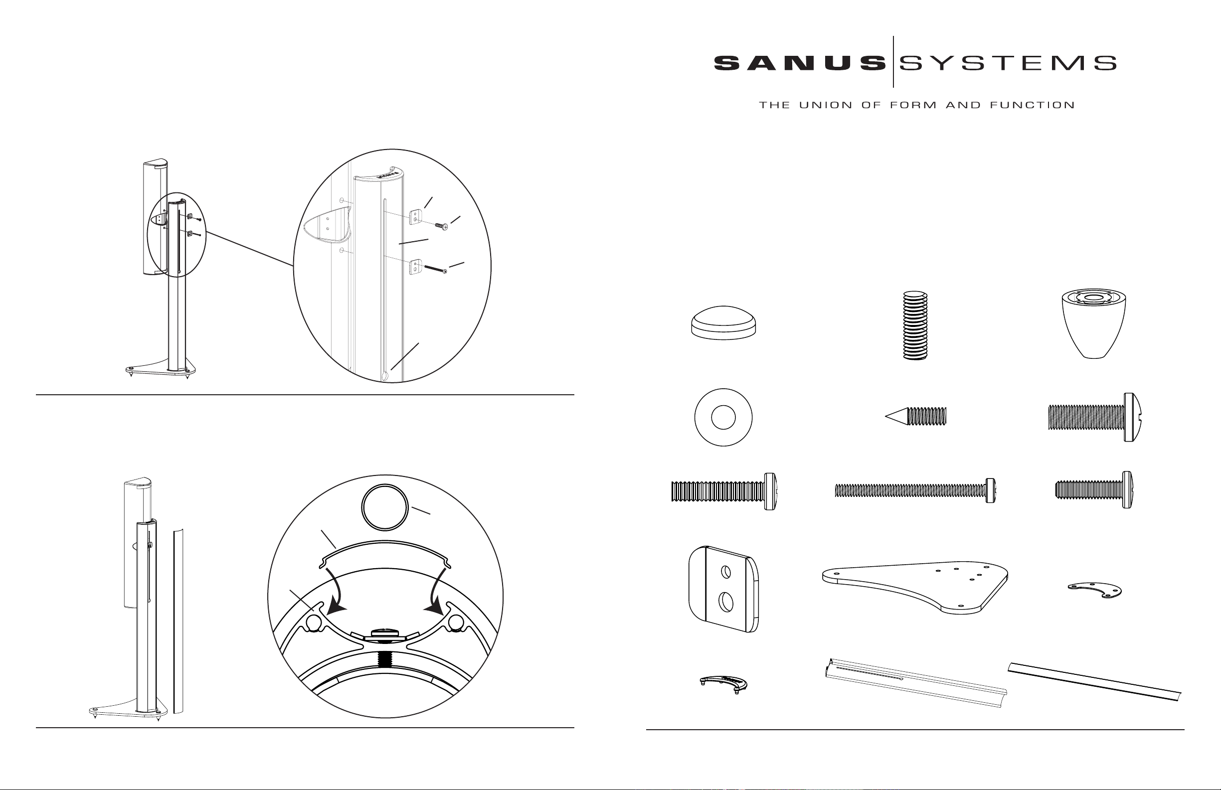
Step 6: Attach Speaker to Pillar
Attach the speaker wire to the speaker and place it through the wire management hole that is labeled in the Detailed View of Diagram 6.
Proceed to attach the speaker by placing the appropriate Bolt (g,h,i) through the corresponding hole in the Bracket (j), then through the slot in
the Pillar (n) and finally threading it into the speaker. If there is a second attachment point on the speaker, repeat the process. Using a phillips
screw driver, tighten the bolt or bolts until the speaker is attached securely. Some speakers will require only one bolt and bracket to be used.
Note: When using the M4 x 50 Bolt (h), use the smaller hole in the Bracket (j). When using either of the 1/4 - 20 Bolts (g, i), use
the larger hole in the Bracket. See the Detailed View of Diagram 6 for assistance.
j
g, i
n
h
wire
management
hole
Diagram 6 Detailed View
Assembly Instructions for Flat Panel Foundations: FF1
Thank you for choosing Sanus Systems Flat Panel Foundations. Please check carefully to make sure there are no missing or defective
parts. Never use defective parts. Improper assembly may cause damage or serious injury. If you have any questions regarding this product, contact Sanus at 800.359.5520 or visit www.sanus.com. Our customer service representatives can quickly assist you with missing or
damaged parts. Replacement parts for Sanus products purchased through authorized dealers can be shipped directly to you. Please call
Sanus Systems before returning products to the point of purchase.
Required Tools: Phillips Screw Driver.
Step 1: Check carefully to make sure all parts and hardware are accounted for.
Diagram 1: Parts and Hardware (Hardware is shown as a
ctual size) *not shown at same scale
Step 7: Add Wire Cover
Make sure the speaker wire has been run down the Pillar (n). Proceed to snap the plastic Wire Covers (o) into the Grooves in the Pil
lar. See the Top View Diagram 7 for assistance. The speaker wire should run out the space below the Wire Covers just above the glass
Base.
Diagram 7 Top View
foot
wire cover
pillar
(
-
(20) Nylon Washer - d (6) Carpet Spike - e (8) M8 x 25 Bolt - f
(4) 1/4-20 x 1.25 Bolt - g (4) M4 x 50 mm Bolt - h
(4) Bracket - j (2) Base - k* (2) Pad - l*
6) Foot Top - a (6) Foot Stud - b (6) Foot Bottom - c
(4) 1/4 - 20 x .875 Bolt - i
Sanus Systems 2221 Hwy 36 West, Saint Paul, MN 55113 2.14.05
Customer Service: 800.359.5520. See complementary Sanus products at www.sanus.com
(2) Top Cap - m* (2) Pillar - n* (2) Wire Cover - o*
Sanus Systems 2221 Hwy 36 West, Saint Paul, MN 55113 2.14.05
Customer Service: 800.359.5520. See complementary Sanus products at www.sanus.com
Page 2
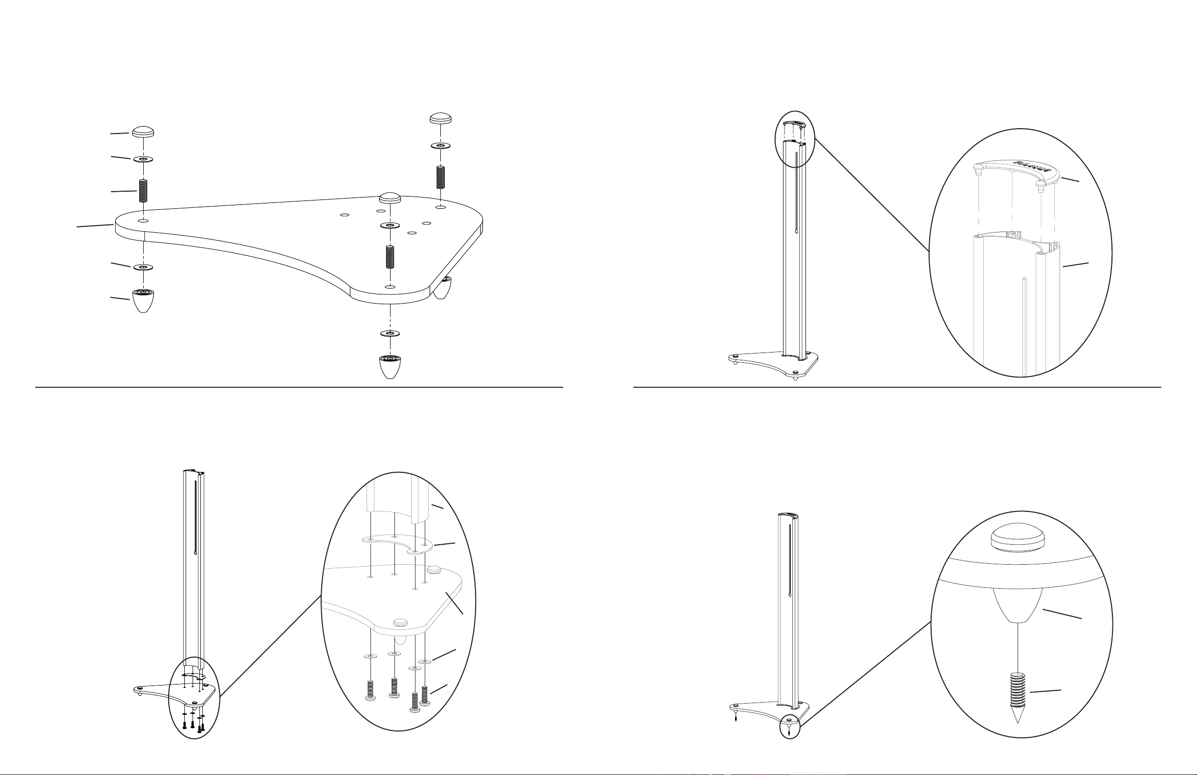
Step 2: Assemble Feet to Base
Step 4: Add Top Cap to Pillar
Assemble the Feet to the Base by placing a Foot Stud (b) through the Base (k), a Nylon Washer (d) and into a Foot Bottom (c). Then,
slide another Nylon Washer over the Foot Stud and thread a Foot Top (a) onto the Foot Stud until the assembly is tight. See Diagram 2
for assistance. Repeat this step for the other two Feet.
a
Diagram 2
d
b
k
d
c
Add the Top Cap (m) by simply press fitting it to the top of the Pillar (n), as shown in the Detailed View of Diagram 4.
Diagram 4
Detailed View
m
n
Step 3: Add Pillar to Base
Add the Pillar (n) to the Base (k) by placing each M8 x 25 Bolt (f) through a Nylon Washer (d), the Base, the Pad (l), and threading into
the Pillar. Proceed to tighten each Bolt until the Pillar is secured to the base. See the Detailed View of Diagram 3 for Assistance.
n
l
k
d
f
Diagram 3 Detailed View
Step 5: Add Carpet Spikes
To add the Carpet Spikes (e), simply thread each one into the bottom of each Foot. You can adjust the Carpet Spikes to level the stand
if needed.
Note: The end of the spikes are sharp and may scratch floors or furniture. All sharp and small objects can be hazardous to children. For this reason the use of the Carpet Spikes is an option. The decision to use steel spiked feet is yours; Sanus Systems is
not liable for damage or injury.
Diagram 5 Detailed View
c
e
 Loading...