

Sanus EFAB IIG User Manual

Assembly Instructions for Model: EFAB-IIg
Thank you for choosing the Sanus Systems Model EFAB-IIg. Every effort has been made to ensure that your Sanus Systems furniture is perfect. If you have questions or feel that there is a problem of any kind, please contact us at 800-359-5520 or at www.sanus.com. We can quickly help with any issues regarding assembly or missing parts. Replacement parts for Sanus systems products purchased through authorized dealers will be shipped directly to you.
Supplied Parts List: (All threaded fasteners are shown full size.)
Metal Base - B
Qty. 1
3˝ Cope Tube - A
Qty. 4
Audio Shelf - C
Qty. 1
|
|
|
|
|
|
|
|
|
|
|
|
|
|
|
|
|
|
|
|
|
|
|
|
|
|
|
|
|
|
|
|
|
|
|
|
|
|
Floor Glide - D |
Top Bolt Washer - E |
Top Bolt - F |
|
|
|
Carpet Spike - G |
|
|
|
|
|
|||||||
|
|
|
|
|
Spike Nut - H |
|||||||||||||
|
Qty. 4 |
Qty. 4 |
Qty. 4 |
|
|
Qty. 4 |
|
|
Qty. 4 |
|||||||||
Glass Protector - I |
|
|
|
|
|
Allen Key - K |
|
|
|
|
|
||
|
|
|
|
|
||
Pan Head Bolt - J |
||||||
Qty. 4 |
Qty. 4 |
Qty. 1 |
||||
|
|
|
|
|
|
|
Sanus Systems 2221 Hwy 36 West, Saint Paul, MN 55113 |
2.13.06 (100018) |
|||||
Customer Service: 800.359.5520. See complementary Sanus products at www.sanus.com
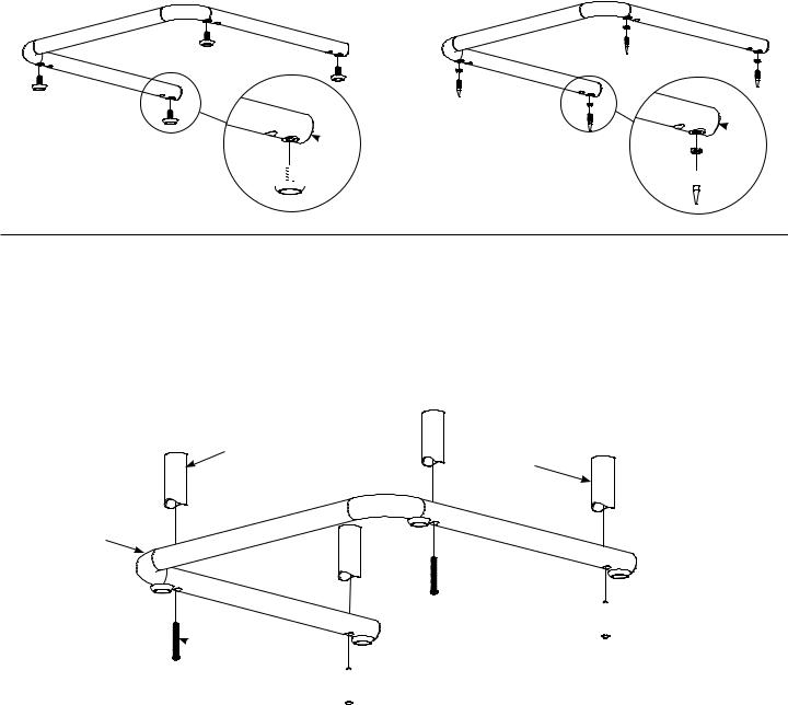
Step 1 - Attach Carpet Spikes or Floor Glides.
 CAUTION: the ends of the Carpet Spikes are very sharp and may scratch non-carpeted flooring, or they may be hazardous to small children. For these reasons Sanus includes Floor Glides.
If the Floor Glides (D) are used, do not install the Carpet Spikes (G), simply thread the Floor Glides into the threaded holes in the Metal Base (B) instead of the Carpet Spikes as shown in diagram 1A.
Thread a Spike Nut (H) onto each Carpet Spike (G); then, screw the Carpet Spikes into the Metal Base (B) as shown in Diagram 1B.
Stand the Metal Base (B) upright and screw the Carpet Spikes (G) in or out until the Metal Base is level; then, turn the Spike Nuts (H) until they are snug against the Metal Base to lock the Carpet Spikes in place. If the Floor Glides (D) are used, simply screw them in or out until the Metal Base (B) is level.
Diagram 1A |
Diagram 1B |
 B
B
 B H
B H

D


 G
G
Step 2 - Attach 3″ Cope Tubes to Metal Base
Place a Pan Head Bolt (J) through each of the four holes in the Metal Base (B); then, thread them into the four 3″ Cope Tubes (A).
Use the Allen Key (K) to tighten the four Pan Head Bolts (J).
Diagram 2
A
A
A
B
A 

 J
J
J 


 J
J

 J
J
 Loading...