

Page 1
Assembly instructions for Model: CFV47
Thank you for choosing Sanus Systems Component Furniture. Please check carefully to make sure there are no missing or
defective parts. Never use defective parts. Improper assembly may cause damage or serious injury. If you have any questions regarding this product, contact Sanus at 800.359.5520 or visit www.sanus.com. Our customer service representatives
can quickly assist you with missing or damaged parts. Replacement parts for Sanus products purchased through authorized
dealers can be shipped directly to you. Please call Sanus Systems before returning products to the point of purchase.
Required Tools: Phillips screw driver
Note: Check carefully to make sure all of the parts and hardware are accounted for.
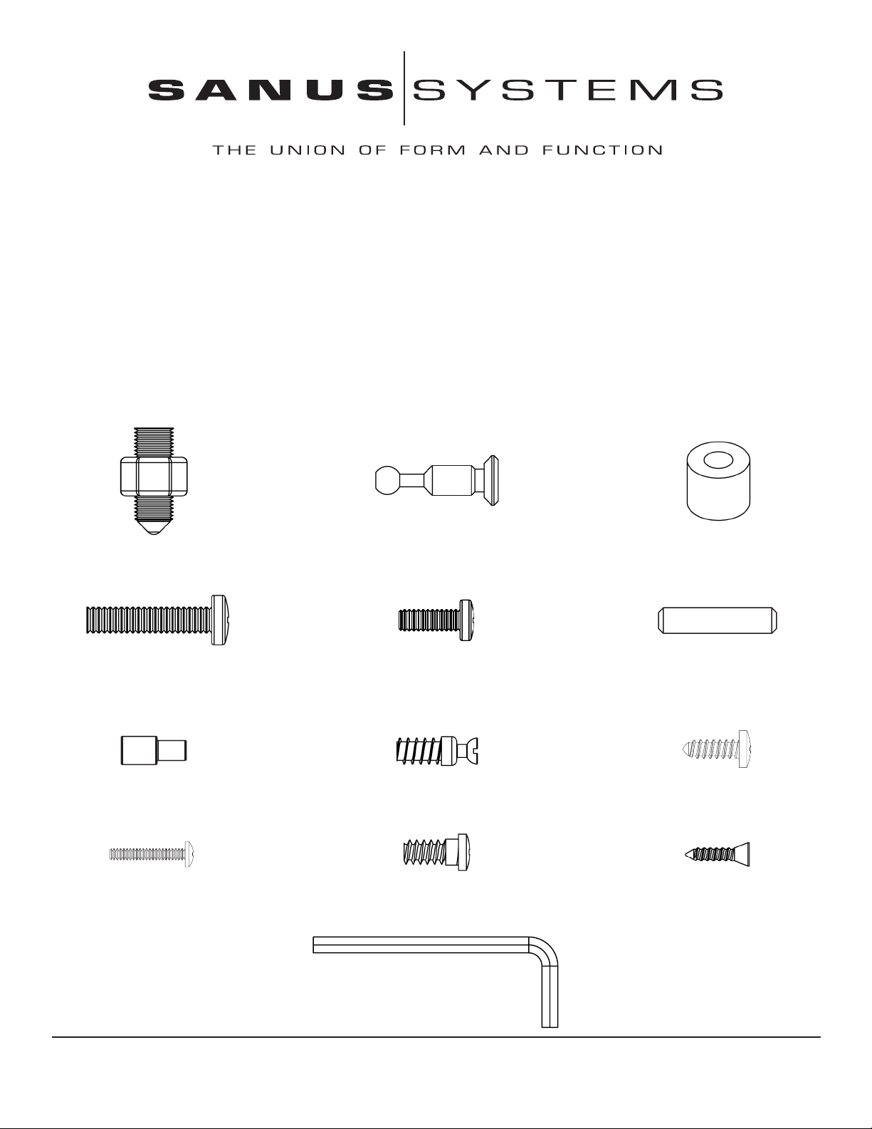
Hardware: Shown at actual size †Some hardware may be pre-assembled
(4) Carpet Spike - a (8) Cam Pin - b (8) Spacer - c
(8) Back Panel Bolt - d (2) Phillips Pan Head Bolt - e (4) Dowel - f
(4) Shelf Pin - g (4) Bottom Shelf Pin - h (4) Wood Screw - i
(2) Knob Bolt - j† (8) Hinge Plate Screw - k† (8) Hinge Screw - l
(1) Allen Key - m
Sanus Systems 2221 Hwy 36 West, Saint Paul, MN 55113 2.18.05
Customer Service: 800.359.5520. See complementary Sanus products at www.sanus.com
Page 2
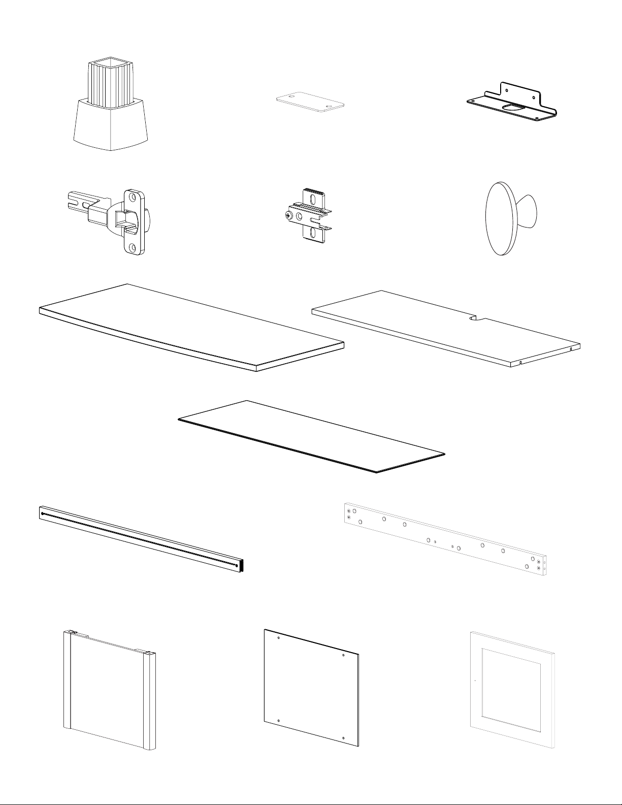
Parts: *Some Parts not shown at same scale
(4) Foot - n* (1) Bottom Shelf Retainer - o* (1) Bottom Shelf Bracket - p*
(4) Hinge - q* (4) Hinge Plate - r* (2) Knob - s*
(1) Top - t (1) Bottom Shelf - u
(1) Glass Shelf - v
(2) Front Rail - w (2) Back Rail - x
(2) Side Panel - y (2) Back Panel - z (2) Door - aa
Page 3
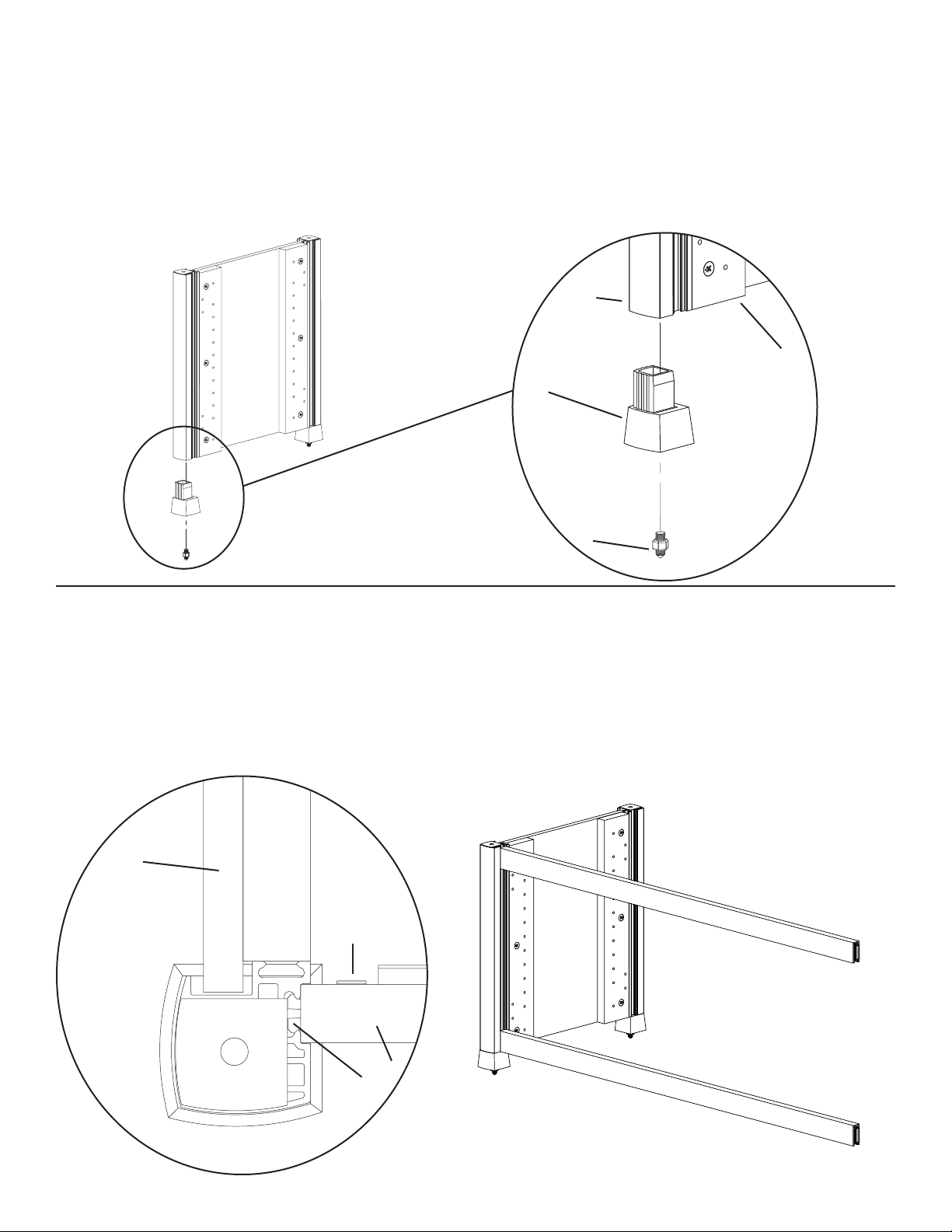
Step 1: Add feet
Add a Foot (n) to each pillar of each Side Panel Assembly (y) as shown in Diagram 1. If you wish to install the Carpet Spikes (a), thread
each Carpet Spike into the foot as seen in Diagram 1. You can adjust the height of the Carpet Spikes with the Nut shown in the Detailed
View of Diagram 1.
Warning: The ends of the carpet spikes are very sharp and may scratch oors or furniture. All sharp objects can be hazardous
to children. For this reason we provide the carpet spikes as an option. Sanus Systems will not be liable for damage or injury.
Diagram 1 Detailed View
pillar
y
n
a
Step 2: Attach the Front Rails to the Side Panel Assembly
Attach the Front Rail (w) to the Side Panel Assembly (y) by sliding the clamp down the groove in the Side Panel pillar as shown in the
Top View of Diagram 2. Make sure the at smooth side of the Front Rail is facing outward and the smooth at side is facing upward
(so the open channel faces down), as shown in Diagram 2. Once the Front Rail is positioned at the bottom of the groove and resting on
the Foot (n), tighten the allen bolt on the back side of the Front Rail so the clamp widens to hold the Front Rail rmly in place. Repeat
process for the other Front Rail, making sure it is level with the top of the corner pillar.
Top View Diagram 2
(Front Left Corner)
y
allen bolt
w
clamp
Page 4

Step 3: Add second Side Panel Assembly
Attach the second Side Panel Assembly (y) by lining up and inserting both Front Rails (w) into the groove in the corner pillar. If the
clamp on the Front Rail will not t in the groove, make sure the allen bolt (labeled in the Top View) is loose so the clamps are close
together. Once you have the Front Rails aligned so the bottom one is resting on the Foot (n), and the top one is level with the corner
pillar, tighten the allen bolt in the back of the Front Rail to widen the clamp to secure it to the pillar. See the Top View of Diagram 3 for
assistance.
Top View
(Front Right Corner) Diagram 3
allen bolt y
w
clamp
Step 4: Attach the Back Rails
Attach the Cam Pins (b) to the Back Rail (x). Make sure the arrow on each Cam is facing the hole in the outside of the Back Rail and
add two Cam Pins to each end of the Back Rail as shown in the Detailed View of Diagram 4. Insert the Cam Pins until there is a small
space between the head of the pin and the Back Rail.
Attach the Back Rail by sliding the cam pins down the groove on the Side Panel pillar as shown in the Top View of Diagram 4. Make
sure the bottom Back Rail is oriented so the threaded holes near the ends are on the top, and the Cams face inside the cabinet, as seen in
Diagram 4. Make sure the top Back Rail is oriented so the threaded holes near the ends are on the bottom, and the Cams face inside the
cabinet, as seen in Diagram 4. Once the Back Rail is resting on the Foot (p), tighten the cams labeled in Diagram 4 to hold it in place.
Diagram 4
Top View
Detailed View (back left corner)
b x
cam
b
y
x
Page 5

Step 5: Add the Back Panel
Insert a Back Panel Bolt (d) through the Back Panel (z), a Spacer (c) and thread it into the Back Rail (x) as seen in the Detailed View of
Diagram 5. Repeat the process until all 8 Back Panel Bolts are attached to the Back Rails. Proceed to tighten the Back Panel Bolts.
Note: Position of Top Back Rail may need to be adjusted for the Back Panel to t properly.
Diagram 5 Detailed View
x
c
d z
Step 6: Add Bottom Shelf Bracket
Thread a Phillips Pan Head Bolt (e) though each hole in the Bottom Shelf Bracket (p), and into the Back Rail (x) as seen in the Detailed
View of Diagram 6. Do not fully tighten the Phillips Pan Head Bolts during this step.
Diagram 6
Detailed View
x
e
p
Page 6

Step 7: Add Bottom Shelf
Thread a Bottom Shelf Pin (h) into the Side Panel (y) as shown in the Detailed View of Diagram 7. Repeat process until all four Bottom
Shelf Pins have been inserted into the Side Panel. Proceed to press t the Bottom Shelf (u) so it is locked into the Bottom Shelf Pins.
Detailed View Diagram 7
y
u
h
Step 8: Attach Brackets to Bottom Shelf
Gently rotate the cabinet so it is resting on its back. Thread a Wood Screw (i) through each hole in the Bottom Shelf Retainer (o) and
into the Bottom Shelf (u) as seen in Detailed View A of Diagram 8. Next, Thread a Wood Screw through each hole in the Bottom Shelf
Bracket (p) and into the Bottom Shelf as seen in Detailed View B of Diagram 8. Proceed to tighten all four Wood Screws with a phillips
screw driver. Once complete, tighten the Phillips Pan Head Bolts from Step 6 until they are tight.
Detailed View A
Diagram 8
u
Detailed View B
o
i u
p
i
Page 7

Step 9: Add Glass Shelf
To add the Glass Shelf (v), insert 4 Shelf Pins (g) at the desired height into the Side Panels (y) as shown in the Detailed View of Diagram
9. Proceed to place the Glass Shelf on the Shelf Pins.
Detailed View
Diagram 9
v
g
y
Step 10: Fit Top to assembly
Insert a Dowel (f) into each corner hole in the bottom side of the Top (t). Gently tap the Dowels in. Press t the Top to the assembly so
the Dowels go into the holes in the corner pillars as seen in the Detailed View of Diagram 10. Make sure the Top is ush with the corner
pillars.
Detailed View
Diagram 10 t
f
corner pillar
Page 8

Step 11: Prepare the Door
Insert a Knob Bolt (j) through the backside of the Door (aa) and proceed to thread it into the Knob (s). Tighten until the Knob is ush
with the front side of the door. See the Detailed View of Diagram 11a for assistance.
Attach the Hinge (q) to the Door (aa) by threading a Hinge Screw (l) through each hole in the Hinge and into the Side Door. See the
Detailed View of Diagram 11b for assistance. Tighten each Hinge screw until the Hinge is secure to the Side Door. Repeat the process
for the second Hinge. Repeat both processes for the second Door.
Diagram 11a Detailed View A Diagram 11b
Detailed View B
aa
j
s aa
l q
Step 12: Add Doors
Attach the Hinge Plates (r) by threading a Hinge Plate Screw (k) through each hole in the Hinge Plate and into the Side Panel (y) as
shown in the Detailed View of Diagram 12. Repeat the process until both Hinge Plates are attached. Proceed to tighten the Hinge Plate
Screws with a phillips screw driver until tight.
To attach each Hinge (q) to its Hinge Plate, the bolt along the back center of the Hinge Plate must be loose during installation. The slot
on the end of the Hinge will t around the bolt on the Hinge Plate. The top and bottom Hinges should engage at the same time as shown
in Diagram 12. Once the two parts of the Hinge are mated, tighten the bolt on the Hinge Plate rmly with a screwdriver.
Detailed View Diagram 12
r k
y
q
Step 13: Hinge Adjustment
Each hinge Assembly is adjustable in multiple directions. See Diagram 13 for assistance.
Diagram 13
Side Adjustment Depth Adjustment Height Adjustment
Sanus Systems 2221 Hwy 36 West, Saint Paul, MN 55113 2.18.05
Customer Service: 800.359.5520. See complementary Sanus products at www.sanus.com
 Loading...