

Page 1
Assembly Instruction for Sanus Systems Component Furnture Model: CFBT
Thank you for choosing Sanus Systems Component Furniture. Please check carefully to make sure there are no missing or defective
parts. Never use defective parts. Improper assembly may cause damage or serious injury. If you have any questions regarding this product, contact Sanus at 800.359.5520 or visit www.sanus.com. Our customer service representatives can quickly assist you with missing or
damaged parts. Replacement parts for Sanus products purchased through authorized dealers can be shipped directly to you. Please call
Sanus Systems before returning products to the point of purchase.
REQUIRED TOOLS:
SUPPLIED PARTS:
(6) Screw - a (2) Bracket - b
(1) Cross Brace - c (1) Bridge - d
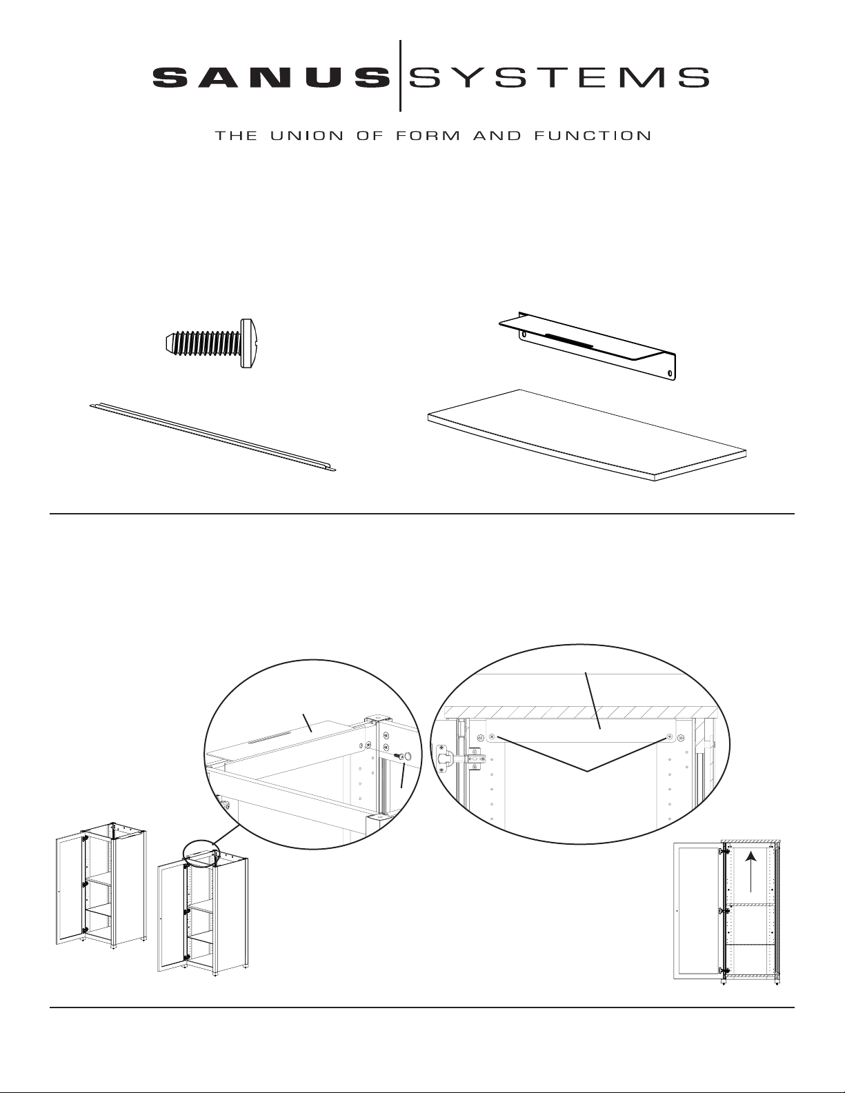
Step 1: Attach the Brackets: Remove the Top from each CFA56. Place a Bracket (b) onto each of the CFA56 audio stands as shown in
Detailed View A of Diagram 1a. Orient the Brackets so that the two small slots line up with the top shelf pin hole in the CFA56 and the long
slot hangs out over the outside edge of the cabinet. Lightly tighten two Screws (a) through the slots in the Bracket and into the top holes in
the Side Panel Assembly of the CFA56. Repeat this step on the opposite side of the second CFA56 so that the long slot in each Bracket is
between the two cabinets as shown in Diagram 1. Next, place the Tops back onto each audio stand. Finally, slide each of the Brackets up until
it is flush with the top of the audio stand and tighten the two Screws firmly as shown in Detailed View B of Diagram 1b.
Detailed View B
Detailed View A
b
Philips Screw Driver
b
a
a
Diagram 1b
Diagram 1a
Sanus Systems 2221 Hwy 36 West, Saint Paul, MN 55113 2.23.05
Customer Service: 800.359.5520. See complementary Sanus products at www.sanus.com
Page 2
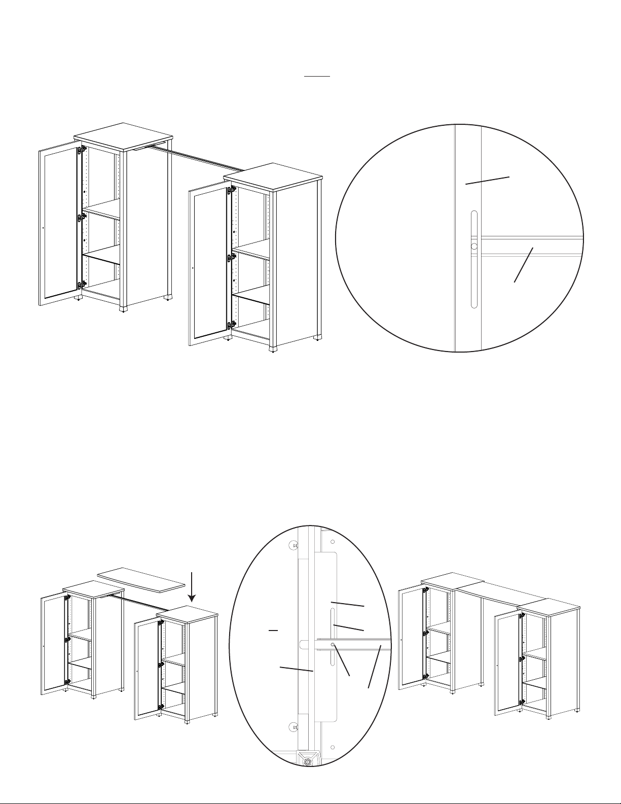
Step 2: Add the Cross Brace
Once the two Brackets (b) are in place, position the two CFA56 stands to aproximately 47” apart. Next, the Cross Brace (c) must be
added. The open channel faces down, and the tab on each end sits under the Brackets added in the previous step. Feed one Cross Brace
tab in under a bracket so it rests on the side panel of the CFA56 and then slide the other end under the second Bracket. The hole in each
end of the Cross Brace should line up with the slot in each of the Brackets as shown in the Top View of Diagram 2.
b
c
Step 3: Add the Top
Place the Bridge (d) down onto the Brackets (b) as shown in Diagram 3. The Bridge should rest on both Brackets and should be flush
against the Top of each of the CFA56 audio stands. The bottom side of the Bridge has 6 holes; three along each side. The middle hole on
each side will be used, the corner holes will remain unused. This middle hole will line up with the hole in the Cross Brace (c), and the
slot in each Bracket as shown in the Bottom View of Diagram 3. The Screws (a) should each pass through one of the holes in the Cross
Brace, then the slot in the Bracket, and fi nally into the hole in the middle of the Bridge. Lightly tighten these two screws.
Diagram 2 Top View
Note: The CFBT can slide backward or forward within the length of the slot in each Bracket (b). Once you have selected the
desired position of the CFBT firmly tighten the two Screws (a).
Bottom View
b
CFA56 slot
CFA56
Side Panel a
c
Diagram 3 Complete Assembly
 Loading...