


• 15P0059B3 •
DCREG2
DCREG4
USER MANUAL
28/05/18 R.07
SOFTWARE VERSION D5.02
• This manual is an integral and essential part of the product. Carefully read the instructions contained
herein as they provide important hints for use and maintenance safety.
• This device shall be used only for the purposes it is aimed at. Any other use is to be considered as
improper and dangerous. The manufacturer is not responsible for any possible damage caused by
improper, erroneous and irrational uses.
• Elettronica Santerno are responsible for the device in its original setting.
• Any changes to the structure or operating cycle of the device must be performed or authorized by
Elettronica Santerno’s Engineering Department.
• Elettronica Santerno are not responsible for the consequences resulting from the use of non-original
spare parts.
• Elettronica Santerno reserve the right to make any technical changes to this manual and the device
without prior notice. Any misprint or spelling mistake will be edited in the new versions of this manual.
• Elettronica Santerno are responsible for the information contained in the original version of the Italian
manual.
• The information contained herein is Elettronica Santerno’s property and cannot be reproduced.
Elettronica Santerno enforce their rights on the drawings and catalogues according to the law.
Elettronica Santerno S.p.A.
Via della Concia, 7 – 40023 Castel Guelfo (BO) Italy
Tel. +39 0542 489711 - Fax +39 0542 489722
santerno.com info@santerno.com
En gl ish

15P0059B3 DCREG2
USER MANUAL DCREG4
2/200
REVISION INDEX
The following subjects covered in this 15P0059B3 User Manual (revision R.07) have been added,
changed or suppressed with respect to the previous revision R.06.
Logo ENERTRONICA GROUP added.
Nameplate modified.
Sections TRANSPORT AND HANDLING, UNPACKING and SCHEDULED MAINTENANCE added.
Indications about Decisive voltages according to EN 61800-5-1 (class A, B or C) added.
Table for UL-APPROVED FUSES added.
Table for SHORT-CIRCUIT CURRENT added.
Notes for CONVERTER AND MOTOR GROUND CONNECTIONS added.
Normative references for LOW VOLTAGE DIRECTIVE (2014/35/EU) and ELECTROMAGNETIC
COMPATIBILITY DIRECTIVE (2014/30/EU) updated.
Imot and Iarm nom nomenclatures rectified for OVERLOAD CAPABILITY.
Minimum value for parameter P010: Maximum speed rectified.
EMC CHARACTERISTICS AND INPUT FILTERS section updated; table for Class B external filters
added.
References to old control boards or to older SW versions than the currently implemented version
removed.
OTHER MANUALS MENTIONED
The following manuals from Elettronica Santerno are mentioned throughout this User Manual:
• 16B0301B3 PC-DCREG INTERFACING VIA MODBUS
• 16B0221B3 PC-DCREG INTERFACING VIA PROFIBUS-DP
• 16B0211B1 DCREG FIRMWARE UPDATING VIA SERIAL COMMUNICATION
• 15P0068B1 CU400 – User Manual

DCREG2 15P0059B3
DCREG4 USER MANUAL
3/200
TABLE OF CONTENTS
REVISION INDEX ......................................................................................................................................... 2
OTHER MANUALS MENTIONED ................................................................................................................ 2
TABLE OF CONTENTS................................................................................................................................ 3
1 DELIVERY CHECK .............................................................................................................................. 9
1.1 NAMEPLATE ............................................................................................................................... 9
1.2 TRANSPORT AND HANDLING ................................................................................................ 10
1.3 UNPACKING ............................................................................................................................. 11
2 START-UP ......................................................................................................................................... 13
2.1 INTRODUCTION ....................................................................................................................... 13
2.2 PRELIMINARY CHECKS .......................................................................................................... 13
2.3 SCHEDULED MAINTENANCE ................................................................................................. 14
2.4 MAIN CHECKS AND CONFIGURATIONS ............................................................................... 15
2.5 SPEED CONTROL MODE OPERATION.................................................................................. 17
2.6 RAMP CONFIGURATION IN SPEED CONTROL MODE ........................................................ 18
2.7 SPEED CONTROL OPTIONS .................................................................................................. 18
2.8 CURRENT (TORQUE) CONTROL MODE OPERATION ......................................................... 20
2.9 CURRENT LIMIT CONTROL OPTIONS ................................................................................... 21
2.10 ANALOG AND DIGITAL OUTPUTS ......................................................................................... 21
2.11 BACKUP AND RESTORATION OF STORED PARAMETERS ................................................ 22
3 GENERAL CHARACTERISTICS ....................................................................................................... 23
3.1 GENERAL DESCRIPTION ........................................................................................................ 23
3.2 RATINGS .................................................................................................................................. 28
3.3 DCREG SIZE 1 OVERALL DIMENSIONS ................................................................................ 33
3.4 DCREG SIZE 1 THROUGH-PANEL ASSEMBLY ..................................................................... 34
3.5 DCREG SIZE 2 OVERALL DIMENSIONS ................................................................................ 35
3.6 DCREG SIZE 2A OVERALL DIMENSIONS .............................................................................. 36
3.7 DCREG SIZE 2 AND SIZE 2A THROUGH-PANEL ASSEMBLY .............................................. 37
3.8 DCREG MODULAR.S SIZE A POWER SECTION OVERALL DIMENSIONS ......................... 38
3.9 DCREG MODULAR.S SIZE B POWER SECTION OVERALL DIMENSIONS ......................... 39
3.10 DCREG MODULAR.S SIZE C POWER SECTION OVERALL DIMENSIONS ......................... 40
3.11 DCREG MODULAR.S SIZE D POWER SECTION OVERALL DIMENSIONS ......................... 41
3.12 DCREG MODULAR.S SIZE E POWER SECTION OVERALL DIMENSIONS ......................... 42
3.13 DCREG MODULAR.S SIZE F POWER SECTION OVERALL DIMENSIONS.......................... 43
3.14 DCREG MODULAR.S SIZE G POWER SECTION OVERALL DIMENSIONS ......................... 44
3.15 DCREG MODULAR.S SIZE H POWER SECTION OVERALL DIMENSIONS ......................... 45
3.16 DCREG MODULAR.S SIZE I POWER SECTION OVERALL DIMENSIONS ........................... 46
3.17 DCREG MODULAR.S SIZE J POWER SECTION OVERALL DIMENSIONS .......................... 47
3.18 DCREG MODULAR.S SIZE K POWER SECTION OVERALL DIMENSIONS ......................... 48
3.19 DCREG MODULAR.S SIZE L POWER SECTION OVERALL DIMENSIONS .......................... 49
3.20 DCREG MODULAR.S CONTROL UNIT OVERALL DIMENSIONS ......................................... 50
3.21 DCREG SIZE 1...2A POWER CONNECTIONS ........................................................................ 51
3.22 DCREG MODULAR.S POWER CONNECTIONS..................................................................... 53
3.23 DCREG MODULAR.S POWER UNIT WIRING DIAGRAM ...................................................... 55
3.24 DCREG MODULAR.S CONTROL UNIT TERMINALS ............................................................. 56
3.25 SUPPLY AND POWER TERMINALS ....................................................................................... 57
3.26 LEGEND FOR POWER CONNECTIONS................................................................................. 59
3.27 CROSS-SECTIONS OF THE POWER CABLES AND SIZES OF THE PROTECTIVE DEVICES
61
3.28 SWITCHING THREE-PHASE INDUCTANCE .......................................................................... 62
3.29 UL-APPROVED FUSES ............................................................................................................ 63
3.30 SHORT-CIRCUIT CURRENT ................................................................................................... 64
3.31 CONVERTER AND MOTOR GROUND CONNECTION .......................................................... 65
3.32 DCREG SIGNAL CONNECTIONS ............................................................................................ 66
3.33 SIGNAL TERMINALS ................................................................................................................ 67
3.34 LEDS AND TEST POINTS ON THE CONTROL BOARD......................................................... 70
3.35 FEEDBACK FROM ENP/NR ..................................................................................................... 71
3.36 MILLIAMPERE INPUT / OUTPUT SIGNALS ............................................................................ 72
4 KEYPAD AND ALPHANUMERIC DISPLAY ...................................................................................... 74

15P0059B3 DCREG2
USER MANUAL DCREG4
4/200
4.1 KEYS OPERATING MODES .................................................................................................... 74
4.2 FUNCTIONS DISPLAYED BY THE LEDS ................................................................................ 76
4.3 LOCAL OPERATING MODE..................................................................................................... 77
4.4 REMOING THE KEYPAD ......................................................................................................... 78
5 FIRMWARE STRUCTURE ................................................................................................................ 81
5.1 GENERAL ................................................................................................................................. 81
5.2 BLOCK DIAGRAM .................................................................................................................... 82
5.3 PARAMETER COPY ................................................................................................................. 91
6 SPECIAL FEATURES ........................................................................................................................ 93
6.1 AUTOTUNING .......................................................................................................................... 93
6.2 RAMPS OVER THE REFERENCE ........................................................................................... 95
6.3 MOTOR POTENTIOMETER ..................................................................................................... 96
6.4 CURRENT LIMITATION ........................................................................................................... 97
6.5 OPERATION QUADRANTS ..................................................................................................... 99
6.6 MOTOR HEATING THERMAL IMAGE ................................................................................... 102
6.7 FIELD REGULATOR ............................................................................................................... 103
6.8 CONFIGURABLE DIGITAL OUTPUTS ................................................................................... 106
6.9 ADAPTIVE SPEED PARAMETERS ........................................................................................ 108
6.10 ELECTROMAGNETS APPLICATION ..................................................................................... 110
6.10.1 Drive Power Connections And Protecting Devices ......................................................... 110
6.10.2 DCREG4 Electromechanical Diagram For Reference Switching ................................... 113
6.10.3 DCREG4 Setting Parameter Values Different From Default Values .............................. 114
6.10.4 DCREG4 Operation Description ..................................................................................... 115
6.10.5 DCREG2 Electromechanical Diagram For Reference Switching ................................... 117
6.10.6 DCREG2 Setting Parameter Values Different From Default Values .............................. 118
6.10.7 DCREG2 Operation Description ..................................................................................... 119
6.10.8 Energizing/Deenergizing Current Patterns ..................................................................... 120
6.10.9 Operation With Back-up Batteries .................................................................................. 121
6.10.10 Alarms ............................................................................................................................ 122
7 OPERATION PARAMETERS .......................................................................................................... 123
7.1 MEASURE PARAMETERS ..................................................................................................... 123
7.1.1 M000: Reference Applied to the Ramps ............................................................................. 123
7.1.2 M001: Speed / Voltage Feedback ....................................................................................... 123
7.1.3 M002: Overall Speed/Voltage Reference ........................................................................... 124
7.1.4 M003: Armature Current Reference ................................................................................... 124
7.1.5 M004: Armature Current ..................................................................................................... 124
7.1.6 M005: Thyristor Firing Delay Angle ..................................................................................... 124
7.1.7 M006: Armature Voltage ..................................................................................................... 124
7.1.8 M007: Back-electromotive force ......................................................................................... 124
7.1.9 M008: Mains Frequency ...................................................................................................... 125
7.1.10 M009: Mains Voltage ...................................................................................................... 125
7.1.11 M010: Auxiliary Analog Input 1 to Terminals 11 and 13 ................................................. 125
7.1.12 M011: Auxiliary Analog Input 2 on Terminal 17 .............................................................. 125
7.1.13 M012: Auxiliary Analog Input 3 on Terminal ................................................................... 126
7.1.14 M013: Up/Down Internal Reference ............................................................................... 126
7.1.15 M014: Main Analog Input to Terminals 5 and 7 .............................................................. 126
7.1.16 M015: Serial Connection Reference ............................................................................... 126
7.1.17 M016: Field Bus Reference ............................................................................................ 127
7.1.18 M017: Field Current Reference ...................................................................................... 127
7.1.19 M018: Field Current ........................................................................................................ 127
7.1.20 M019: Analog Output 1 on Terminal 8 ............................................................................ 127
7.1.21 M020: Analog Output 2 on Terminal 10 .......................................................................... 127
7.1.22 M021: Final Internal State of Digital Inputs ..................................................................... 128
7.1.23 M022: Digital Output State .............................................................................................. 128
7.1.24 M023: Field Regulator Internal Digital Input State .......................................................... 128
7.1.25 M024: Output Power ....................................................................................................... 129
7.1.26 M025: Motor Torque ....................................................................................................... 129
7.1.27 M026: EnP/Nr Frequency ............................................................................................... 129
7.1.28 M027: Drive Life .............................................................................................................. 129
7.1.29 M028: PhaseSeq ............................................................................................................ 129
7.1.30 M029: Digital Input State from Terminal Board .............................................................. 130
7.1.31 M030: Digital Input State from Serial Connection ........................................................... 130

DCREG2 15P0059B3
DCREG4 USER MANUAL
5/200
7.1.32 M031: Digital Input State from Bus Field ........................................................................ 131
7.2 PROGRAMMING PARAMETERS ........................................................................................... 132
7.2.1 P000: Programming P/N ..................................................................................................... 132
7.2.2 P001: Autotuning Command ............................................................................................... 132
7.2.3 P002: Parameter Copy Command ...................................................................................... 133
7.2.4 P003: Programming Level .................................................................................................. 133
7.2.5 P004: Page Displayed at Power on ..................................................................................... 134
7.2.6 P005: Measure Parameter Display on the KeyPad Page .................................................. 134
7.2.7 P006: Measure Parameter Selection on the KeyPad Page ............................................... 134
7.2.8 P010: Max. Speed ............................................................................................................... 134
7.2.9 P011: Max. Armature Voltage ............................................................................................. 135
7.2.10 P012: Speed / Voltage Reference Polarity ..................................................................... 135
7.2.11 P013: Max. Positive Speed / Voltage Reference ............................................................ 136
7.2.12 P014: Min. Positive Speed / Voltage Reference ............................................................. 136
7.2.13 P015: Max. Negative Speed / Voltage Reference .......................................................... 136
7.2.14 P016: Min. Negative Speed / Voltage Reference ........................................................... 137
7.2.15 P030: Rise Ramp of the Positive Reference .................................................................. 137
7.2.16 P031: Fall Ramp of the Positive Reference .................................................................... 137
7.2.17 P032: Rise Ramp of the Negative Reference ................................................................. 138
7.2.18 P033: Fall Ramp of the Negative Reference .................................................................. 138
7.2.19 P034: Stop Ramp of the Positive Reference .................................................................. 138
7.2.20 P035: Stop Ramp of the Negative Reference ................................................................ 139
7.2.21 P036: Rise Ramp of the Jog Reference ......................................................................... 139
7.2.22 P037: Fall Ramp of the Jog Reference .......................................................................... 139
7.2.23 P038: Ramp Initial Rounding .......................................................................................... 140
7.2.24 P039: Ramp Final Rounding ........................................................................................... 140
7.2.25 P040: Ramp of the Up/Down Internal Reference ........................................................... 140
7.2.26 P050: Bridge A First Current Limit .................................................................................. 140
7.2.27 P051: Bridge B First Current Limit .................................................................................. 141
7.2.28 P052: Bridge A Second Current Limit ............................................................................. 141
7.2.29 P053: Bridge B Second Current Limit ............................................................................. 141
7.2.30 P054: First to Second Current Limit Speed .................................................................... 142
7.2.31 P055: Hyperbolic Pattern End Current Limit ................................................................... 142
7.2.32 P056: Hyperbolic Limit Start Speed ................................................................................ 142
7.2.33 P057: Hyperbolic Limit End Speed ................................................................................. 142
7.2.34 P058: Current Limit Decrease Per Cent ......................................................................... 143
7.2.35 P059: Ramp Over the Current Reference ...................................................................... 143
7.2.36 P060: Bridge A Current Overlimit ................................................................................... 143
7.2.37 P061: Bridge B Current Overlimit ................................................................................... 144
7.2.38 P062: Overlimit Digital Output Delay .............................................................................. 144
7.2.39 P070(076): Speed Loop Proportional Gain (Second Gain) ............................................ 144
7.2.40 P071(077): Speed Loop Integral Time (Second Time) ................................................... 145
7.2.41 P073(079): Speed Loop Adapted Proportional Gain (Second Gain) .............................. 145
7.2.42 P074(080): Speed Loop Adapted Integral Time (Second Time) .................................... 145
7.2.43 P082: Speed Parameter Auto Adaptation ....................................................................... 146
7.2.44 P083: First Speed Error for Auto Adaptation .................................................................. 146
7.2.45 P084: Second Speed Error for Auto Adaptation ............................................................. 146
7.2.46 P085: Speed Integral Time Increment During Ramp...................................................... 147
7.2.47 P086: Armature Compensation ...................................................................................... 147
7.2.48 P087: Offset over the Speed Error ................................................................................. 147
7.2.49 P088: Armature Resistive Drop ...................................................................................... 147
7.2.50 P100: Current Loop Proportional Gain ........................................................................... 148
7.2.51 P101: Current Loop Integral Time with Discontinuous Current Conduction ................... 148
7.2.52 P102: Current Loop Integral Time with Continuous Current Conduction ....................... 148
7.2.53 P103: Armature Equivalent Resistive Drop .................................................................... 149
7.2.54 P104: Armature Equivalent Inductive Drop ..................................................................... 149
7.2.55 P110: Field Regulator Voltage Loop Proportional Gain .................................................. 149
7.2.56 P111: Field Regulator Voltage Loop Integral Time ......................................................... 149
7.2.57 P120: Speed / Voltage Main Input Polarity ..................................................................... 150
7.2.58 P121: Speed / Voltage Main Input Bias .......................................................................... 150
7.2.59 P122: Speed / Voltage Main Input Gain.......................................................................... 150
7.2.60 P123: Main Current Input Polarity ................................................................................... 151

15P0059B3 DCREG2
USER MANUAL DCREG4
6/200
7.2.61 P124: Current Main Input Bias ........................................................................................ 151
7.2.62 P125: Current Main Input Gain ....................................................................................... 151
7.2.63 P126(129)(132): Polarity for Auxiliary Analog Input 1(2)(3 ............................................. 152
7.2.64 P127(130)(133): Auxiliary Analog Input 1(2)(3) Bias ...................................................... 152
7.2.65 P128(131)(134): Auxiliary Analog Input 1(2)(3) Gain ..................................................... 152
7.2.66 P150(153): Analog Output 1(2) Configuration ................................................................ 153
7.2.67 P151(154): Analog Output 1(2) Bias............................................................................... 154
7.2.68 P152(155): Analog Output 1(2) Gain .............................................................................. 154
7.2.69 P156: Analog IOut Polarity on Terminal 6 ...................................................................... 154
7.2.70 P157(158): Analog output polarity 1(2) ........................................................................... 155
7.2.71 P170(176)(182)(188)(194): Digital Output 1(2)(3)(4)(5) Configuration ........................... 156
7.2.72 P171(177)(183)(189)(195): Digital Output 1(2)(3)(4)(5) On Delay ................................. 157
7.2.73 P172(178)(184)(190)(196): Digital Output 1(2)(3)(4)(5) Off Delay ................................. 157
7.2.74 P173(179)(185)(191)(197): Digital Output 1(2)(3)(4)(5) Switching Level ....................... 158
7.2.75 P174(180)(186)(192)(198): Digital Output 1(2)(3)(4)(5) Switching Hysteresis ............... 159
7.2.76 P175(181)(187)(193)(199): Digital Output 1(2)(3)(4)(5) Contact Logic .......................... 159
7.2.77 P211(212)(213)(214)(215)(216)(217): Preset Run Reference 1(2)(3)(4)(5)(6)(7 ........... 160
7.2.78 P221: Jog Ramp Selection ............................................................................................. 161
7.2.79 Jog Reference 1(2)(3) .................................................................................................... 161
7.2.80 P230: Min. Firing Angle .................................................................................................. 162
7.2.81 P231: Max. Firing Angle ................................................................................................. 162
7.2.82 P240: Low Pass Filter over the Speed / Voltage Error ................................................... 162
7.2.83 P250: Up / Down Internal Reference Polarity ................................................................. 162
7.2.84 P251: Up / Down Internal Reference Restoration at Power On ..................................... 162
7.3 CONFIGURATION PARAMETERS ........................................................................................ 163
7.3.1 C000: Motor Rated Current ................................................................................................. 163
7.3.2 C001: Current for Motor Thermal Protection ...................................................................... 163
7.3.3 C002: Time Constant for Motor Thermal Protection ........................................................... 163
7.3.4 C010: Motor Field Rated Current ........................................................................................ 164
7.3.5 C011: Field Weakening Start Rated Speed ........................................................................ 164
7.3.6 C012: Rated Armature Voltage at Field Weakening ........................................................... 164
7.3.7 C014: Standstill Field Current ............................................................................................. 165
7.3.8 C015: Standstill Field Current Decrease Delay ................................................................... 165
7.3.9 C016: Field Weakening Min. Current .................................................................................. 165
7.3.10 C017: Boost over the Field Current ................................................................................ 166
7.3.11 C018: Boost Duration on Field Current........................................................................... 166
7.3.12 C030: Nominal Mains Voltage ........................................................................................ 166
7.3.13 C050: Speed / Voltage Loop Operation .......................................................................... 167
7.3.14 C051: Current Loop Operation ....................................................................................... 167
7.3.15 C052: Field Regulator Voltage Loop Operation .............................................................. 167
7.3.16 C060: First Quadrant Selection ...................................................................................... 168
7.3.17 C061: Second Quadrant Selection ................................................................................. 168
7.3.18 C062: Third Quadrant Selection ..................................................................................... 168
7.3.19 C063: Fourth Quadrant Selection ................................................................................... 168
7.3.20 C070: Feedback Selection ............................................................................................. 169
7.3.21 C072: EnP/Nr Pulses/Rev .............................................................................................. 169
7.3.22 C074: Tacho Transduction Ratio .................................................................................... 169
7.3.23 C090: AlarmAutoReset Number ..................................................................................... 170
7.3.24 C091: ResetTime of AutoresetNumber .......................................................................... 170
7.3.25 C092: PowerOnReset ..................................................................................................... 170
7.3.26 C093: Autoreset after Mains Failure ............................................................................... 170
7.3.27 C094: StartSafety ........................................................................................................... 171
7.3.28 C100: LOCAL / MIXED Selection Enabling .................................................................... 171
7.3.29 C101: Delay from Starting Enabling ............................................................................... 171
7.3.30 C102: ZeroingTime ......................................................................................................... 172
7.3.31 C103: Emergency Stop ................................................................................................... 172
7.3.32 C105(106)(107)(108): Source Reference Selection 1(2)(3)(4) ....................................... 173
7.3.33 C110(111)(112): Command Source Selection 1(2)(3) ................................................... 174
7.3.34 C120(121)(122): Analog Input 1(2)(3) Configuration ...................................................... 175
7.3.35 C130(131)(132)(133)(134)(135): Digital Input 1(2)(3)(4)(5)(6) Configuration ................ 177
7.3.36 C141: Alarm A016/017 Trip Delay .................................................................................. 179
7.3.37 C142: Alarm A027 Trip Delay ......................................................................................... 180

DCREG2 15P0059B3
DCREG4 USER MANUAL
7/200
7.3.38 C143: Alarm A028 Trip Delay ......................................................................................... 180
7.3.39 C150: Alarm A001 Trip Disabling ................................................................................... 180
7.3.40 C151: Alarm A004 Trip Disabling ................................................................................... 180
7.3.41 C153: Alarm A006 Trip Disabling ................................................................................... 180
7.3.42 C154: Alarm A007 Trip Disabling ................................................................................... 181
7.3.43 C155: Alarm A008 Trip Management ............................................................................. 181
7.3.44 C156: Alarm A010 Trip Disabling ................................................................................... 181
7.3.45 C157: Alarm A016/017 Trip Disabling ............................................................................ 181
7.3.46 C158: Alarm A027 Trip Disabling ................................................................................... 181
7.3.47 C159: Alarm A028 Trip Disabling ................................................................................... 182
7.3.48 C160: Serial Connection Drive Address ......................................................................... 182
7.3.49 C161: Serial Connection Transmission Speed ............................................................... 182
7.3.50 C162: Serial Connection Parity Control .......................................................................... 182
7.3.51 C163: Master Data Area Base Address.......................................................................... 183
7.3.52 C164: Serial Time Out .................................................................................................... 183
7.3.53 C165: Serial Response Delay ......................................................................................... 183
7.3.54 C170: Load Type ............................................................................................................ 183
8 DIAGNOSTICS ................................................................................................................................ 184
8.1 ALARM PARAMETERS .......................................................................................................... 184
8.1.1 A001: Field Current Failure ................................................................................................. 185
8.1.2 A002: Heatsink Overtemperature ....................................................................................... 185
8.1.3 A003: Armature Overcurrent ............................................................................................... 185
8.1.4 A004: Load Loss ................................................................................................................. 185
8.1.5 A006: Unstable Mains Frequency ....................................................................................... 185
8.1.6 A007: Mains Phase Failure ................................................................................................. 186
8.1.7 A008: Speed Feedback Failure........................................................................................... 186
8.1.8 A009: Field Overcurrent ...................................................................................................... 186
8.1.9 A010: Armature Overvoltage............................................................................................... 186
8.1.10 A011: Auto Tuning Inductance out of Range .................................................................. 186
8.1.11 A012: Mains Frequency out of Range ............................................................................ 186
8.1.12 A013: Synchronization Failure ........................................................................................ 187
8.1.13 A014: AutoTuning Resistance out of Range................................................................... 187
8.1.14 A015: Torque During Current AutoTuning ...................................................................... 187
8.1.15 A016: Mains Overvoltage ............................................................................................... 187
8.1.16 A017: Mains Undervoltage ............................................................................................. 187
8.1.17 A018: AutoTuning Interrupted ......................................................................................... 188
8.1.18 A019: Limitation During Speed AutoTuning .................................................................... 188
8.1.19 A020: ExternalAlarm 1 .................................................................................................... 188
8.1.20 A021: Motor Thermal Protection Trip ............................................................................. 188
8.1.21 A022: Drive Thermal Protection Trip .............................................................................. 188
8.1.22 A023: Field Weakening Min. Current Limit ..................................................................... 188
8.1.23 A024: EEPROM Missing or Blank .................................................................................. 189
8.1.24 A025: Wrong Parameters in EEPROM Work Area ........................................................ 189
8.1.25 A026: EEPROM Wrong Backup Parameters ................................................................. 189
8.1.26 A027: Serial Communication Failure .............................................................................. 189
8.1.27 A028: Connection with Field Bus Failure ........................................................................ 189
8.1.28 A029: External Alarm 2 ................................................................................................... 190
8.1.29 A030: External Alarm 3 ................................................................................................... 190
8.1.30 A031: EEPROM Work Area Internal Data Altered .......................................................... 190
8.1.31 A032: Microcontroller Reset ........................................................................................... 190
8.1.32 A033: Unknown Failure .................................................................................................. 190
8.1.33 Additional Alarms ............................................................................................................ 190
8.2 WARNING PARAMETERS ..................................................................................................... 191
8.2.1 W002: Speed Feedback Loss ............................................................................................. 191
8.2.2 W003: Hardware Limit Current not at Maximum Value ..................................................... 191
8.2.3 W004: Safe Restart after an Alarm Reset .......................................................................... 191
8.2.4 W005: Restart after an Emergency Stop from Keypad ....................................................... 191
8.2.5 W006: Backup Values Stored in RAM ................................................................................ 192
8.2.6 W007: Default Values Stored in RAM ................................................................................. 192
8.2.7 W008: Wrong parameters in EEPROM Work Area ............................................................ 192
8.2.8 W009: Wrong Parameters in EEPROM Backup Area ........................................................ 193
9 EMC CHARACTERISTICS AND INPUT FILTER ............................................................................ 194

15P0059B3 DCREG2
USER MANUAL DCREG4
8/200
10 USER’S PARAMETERS DIFFERENT FROM DEFAULT VALUES ................................................. 197

DCREG2 15P0059B3
DCREG4 USER MANUAL
9/200
1 DELIVERY CHECK
When receiving the unit, check that no damage is visible and its compliance with your requirements. To
do that, refer to the plate (see following figure) located on the converter front side. If the unit is damaged,
contact the insurance company or the supplier.
If the unit is stored before it is used, check that the storage area conditions are acceptable (temperatures
ranging from -20°C and +60°C, relative humidity lower than 95% and no dew).
The warranty covers any manufacturing faults. The manufacturer has no responsibility for damages
occurred during transportation or unpacking.
In no case and in no circumstances, the manufacturer will be responsible for damages or failures due to
wrong usage, abuse, wrong installation or incorrect temperature, humidity or corrosive materials, as well
as for faults caused by operation exceeding the rated values. The manufacturer will not be responsible for
consequential or accidental damages.
The manufacturer provides a 12-month warranty, starting from the delivery date.
1.1 NAMEPLATE
KEY
1. The device is called DCREG4.350. It is an AC/DC digital-operated drive.
2. The device main P/N and size P/N are detailed before and after a full stop respectively
(ELETTRONICA SANTERNO P/Ns).
3. The acronym identifies the configuration consisting of two full-control three-phase bridges in
antiparallel forming the drive power section.
4. The armature section can be supplied with a 500 Vac (max.) three-phase alternate voltage and
according to a 50/60 Hz frequency value, thus absorbing at rated load a three-phase alternate current
equal to 287 A.
5. The field section may be supplied with a single-phase alternate voltage equal to 200 … 500V ac and
according to a 50/60 Hz frequency value, thus absorbing at rated load an alternate current equal to 15 A.
6. The control section may be supplied either with 380 … 500 Vac single-phase alternate voltage or with
a 24 Vdc direct voltage (considering, of course, a different terminal pair).
7. The device is able to supply 520 Vdc (max.) on the armature output, with continuous supply of 350 A
(with a maximum overload of 150 % of the nominal value at a preset duty-cycle).
8. The device is able to supply 425 Vdc (max.) on the field output, with a continuous supply of 1 5A.
8
5
7 6 4
1
2
3

15P0059B3 DCREG2
USER MANUAL DCREG4
10/200
1.2 TRANSPORT AND HANDLING
The DCREG packing ensures easy and safe handling. Handling shall be done using a transpallet or a lift
truck with adequate carrying capacity, in order not to damage the product.
Figure 1: Lifting the packing from underneath

DCREG2 15P0059B3
DCREG4 USER MANUAL
11/200
1.3 UNPACKING
Get near the installation place, then unpack following the instructions provided below.
1. Cut with pincers the plastic straps that fix the package of the DCREG to the pallet.
2. Cut with a cutter the adhesive tape closing the box on the side where the package orientation
symbol is reproduced (see Figure 3).
Figure 2: How to open the packing
Figure 3: “This side up” pictogram
3. Remove the DCREG from its packing by lifting it from its sides. To avoid damaging the packing,
lift the product keeping it horizontal to the floor (see Figure 4).

15P0059B3 DCREG2
USER MANUAL DCREG4
12/200
Figure 4: The DCREG is unpacked
4. Put all the packing elements in the box and store it in a dry environment.
Figure 5: DCREG packing box with the internal protective elements

DCREG2 15P0059B3
DCREG4 USER MANUAL
13/200
2 START-UP
2.1 INTRODUCTION
This section describes the main checks and operations which should be carried out to achieve an
excellent adjusting of the DCREG drive.
All information contained herein is directed to the Users being already familiar with the use of the keypad.
If need be, refer to the KEYPAD AND ALPHANUMERIC DISPLAY section for further information.
For a clearer drive operation, the drive operating mode is supposed to send references and control
sequence to inputs by means of the terminal board.
This section has to be considered as a simple and useful guide aimed at achieving a proper adjusting of
the device. It covers both the regulations regarding the most common applications and the setting up of
more specific configurations.
For further information about the function of the different hardware terminals or software parameters and
any additional details, refer to the specific sections of the manual.
In particular, it is strongly recommended to refer to the POWER CONNECTIONS and SIGNAL
CONNECTIONS sections for a correct use of the hardware terminals, as well as the BLOCK DIAGRAM
and the PARAMETER LIST section for a proper setting of the software parameters.
2.2 PRELIMINARY CHECKS
2.2.1 When installing the equipment, carefully read the information given on the stick-on plate fitted on
the front panel and make sure that the supply voltage value required to supply the power section at bars
L1-2-3 does not exceed the maximum value advised (standard value: 440 Vac for DCREG2 and
DCREG4). Check also that the supply voltages for the field regulator on terminals E1-2 and for the
control section on terminals 53-54 is included within the suggested range.
Of course, the latter requirement shall not be necessary whenever the user is going to supply the control
section with a 24 Vdc direct voltage on terminals 40-42. This is always possible even without making any
hardware modification.
NOTE
The standard equipment may be supplied on terminals 53-54 (control
section) with a single-phase alternate voltage between 380 … 500 Vac. On
demand, the device may be supplied on terminals 53-54 a with single-phase
alternate voltage between 200 … 240 Vac.
The standard equipment may be supplied through terminals E1-2 (field
regulator) with a single-phase voltage ranging from 200 to 500 Vac.
2.2.2 Check also that the device is not oversized compared to the motor rated current. That means that
the motor current value should not be lower than the 75% of the device rated current.
2.2.3 Carefully inspect the wiring by referring to the POWER CONNECTIONS and SIGNAL
CONNECTIONS sections of this manual. In particular, make sure that a NO auxiliary contact of the KM
contactor has been connected in series with the ENABLE contact on terminal 24.
2.2.4 Connect the shield of the screened cables relating to the analog signals to the ground potential as
directly as possible. Use the three collar-shaped cable fasteners situated on the bottom of the control
board supporting guard.

15P0059B3 DCREG2
USER MANUAL DCREG4
14/200
2.3 SCHEDULED MAINTENANCE
If installed in an adequate place, the converter scheduled maintenance is reduced to a minimum. The
minimum maintenance intervals are indicated in the table below.
Maintenance tasks
Minimum frequency
What to do
Check heatsink;
clean, if required
Depending on dust concentration
(every 6…12 months)
See Heatsink section below
Check cooling fans;
replace, if required [*]
Depending on dust concentration
(every 6…12 months)
See Cooling fans section below
Replace cooling fans [*]
Every 6 years
See Cooling fans section below
[*] on models with forced air cooling only, i.e. from DCREG.100 and greater.
Heatsink
The cooling fans in the DCREG build up dust from air intake.
Check if the heatsink is clean.
If the heatsink needs to be cleaned, please contact Elettronica Santerno Customer Service.
Cooling fans
The minimum expected durability of the cooling fans of the DCREG is approx. 50,000 hours. Actual
lifetime is based on the operating conditions of the converter, the ambient temperature and the
environmental pollution.
The signs for imminent possible failures are noisy bearings of the fans or worn fins of the fans although
regularly cleaned.
If the DCREG is used in a crucial stage in a process, consider replacing the cooling fan as soon as these
symptoms occur.
Please contact Elettronica Santerno Customer Service to replace the cooling fans.

DCREG2 15P0059B3
DCREG4 USER MANUAL
15/200
2.4 MAIN CHECKS AND CONFIGURATIONS
2.4.1 Supply the control section and the field regulator of the device (except the power section). The
four LEDs which can be seen through the small rectangular slot on the cover should be off.
NOTE
Whenever the display shows an alarm condition, it is necessary to reset it by
simultaneously pressing the “PROG” and “SAVE” keys on the front keypad, or
by means of one of the configurable digital inputs, by programming
parameters C130(131)(132)(133)(134)(135) at the 0:Reset value (this
configuration is a default value on MDI1, terminal 28). Should the alarm not
disappear from the display (and therefore the alarm cause persists), refer to
the ALARM PARAMETERS section of the manual.
NOTE
Before changing the above mentioned parameters and any other parameter,
set the value of parameter P000 to 1.
NOTE
Any other setting up procedure described below should always be saved on
the EEPROM. The non-observance of said instruction shall produce the loss
of all data while turning off the device.
NOTE
The programming level is set in parameter P003; its default value is called
0:Basic. This parameter allows to access and modify few other parameters
only, as it is used for a quick and simple starting. If during the start-up
procedure some parameters which are not included in said programming level
must be changed, set parameter P003 to 1:Advanced.
2.4.2 When no alarm condition is stored, the display generally keeps on showing the Status page,
unless the KeyPad page has been programmed through parameter P004 (FirstPage). When no alarm
condition is stored, the Status page displays the Drive OK message, the software version which has been
installed, the drive type, the drive size and the max. supply voltage that may be applied to the power
section. Otherwise, the Alarms and Warnings are displayed on this page.
Here follows an example of such displaying messages.
Drive OK – D5.01
DCREG4.100 P440
By the example stated above, we understand that no alarm conditions are detected, that the installed
software version is D4.01, and that the device is a DCREG4 with continuous output current equal to 100A
and a maximum three-phase voltage applicable to the power section equal to 440V.
NOTE
The displaying of warning message W003 (Imax[T2] <100%) means that it is
necessary to turn the T2 trimmer completely clockwise, since a partial rotation
clockwise could result in a disagreement between the current limit and the
armature maximum current values to be obtained. More precisely, the
armature maximum current value could be lower than the one required.
The trimmer is located on the right side of the control board, near the two
seven-segment displays which can be seen through the small slot on the drive
cover.
2.4.3 Check the correct operation of the air-cooling unit (if any). Air blowing should be generated from
the bottom to the top.

15P0059B3 DCREG2
USER MANUAL DCREG4
16/200
2.4.4 The device is already supplying the motor field winding, according to the economy function (Field
Economy) set in par. C014.
On parameter C010 (default value: 10%), set the field rated current percentage of the motor with
respect to the field rated current of the drive. The standard values of the drive field rated current are 5A for
DCREG.100max.,15A for DCREG.150min Size 1 and 35A for DCREG Size 2(A) and MODULAR.S.
If need be, you can also change the standstill field current on parameter C014 (default value: 10% of
C010) and the field decrease delay on parameter C015 (default value: 240s).
If a boost on the field current is to be set at the device starting, adjust the value of parameter C017
(default value: 100%) and parameter C018 (default value: 10s) accordingly by enabling the function
through one of the configurable digital inputs; set parameters C130(131)(132)(133)(134)(135) to the
11:FldFrcEnabled value. This, however, could have no effect if the field current increase does not produce
any remarkable field flux increase, thus limiting this function application.
2.4.5 If a dynamic regulation of the field current in field weakening mode is required - with a speed
feedback different than the armature feedback - besides programming par. C010 and C014, program the
motor armature nominal voltage in par. C012 (default value: 1000V), the value per cent of the field
weakening start max. speed in par. C011 (default value: 33%) and the limit at the field current min.
value in par. C016 (default value: 25% of C010).
As stated in the FIELD REGULATOR chapter, set the last value at approx. 75% of the min. motor rated
field current corresponding to its max. speed.
2.4.6 Make sure that the rated value of the power section supply voltage corresponds to the
indications stated in parameter C030 (default value: 400V): if necessary, change the value.
2.4.7 Access parameter C000 (default value: 100%) and set the percentage value of the armature
rated current of the motor with respect to the armature rated current of the drive.
If need be, also set a proper thermal constant on parameter C002 (default value: 300 s) by following the
general indications described in the chapter of this manual dealing with that parameter.
2.4.8 Choose the operating mode of the current loop through parameter C051 (default value: PI). It
is advised to leave the default selection of C051 at value 0:PI Operating in most cases, and to set C051
selection at value 1:Predictive=>J1 only when a very quick response is demanded with a DCREG4 in
enP/Nr or tacho feedback mode, unless the load inertial torque is much lower than the resisting torque.
2.4.9 When choosing the second mode (predictive algorithm), set jumper J1 from position 1 to position
0. Jumper J1 is located on board ES729/1 (installed inside the equipment on ES728/2 control board), then
perform current autotune and set parameter P001 to value 1:Current and follow the instructions
displayed (see also the AUTOMATIC TUNING section). By contrast, if the first mode (PI regulator) is
chosen, go on with the next step of this Procedure.
2.4.10 Access parameter C070 (default value: Tacho feedback: 80 … 250V) and make sure that the
speed feedback type which has been set corresponds to the one required.
2.4.11 Should the feedback be generated from a tacho, check the value set on C070 (among values 0-
1-2), which should match the terminal being used to receive the signal from the tacho.
Then, if the tacho transduction ratio set on parameter C074 (default value: 60V / 1000 RPM) is correct,
set the speed concerning the maximum reference in parameter P010 (default value: 2500RPM) in
r.p.m.
NOTE
Any value being set for parameters C074 and P010 should be programmed in
such a way that product C074•P010 does not exceed 25V if C070 = 0, 80V if
C070 = 1, 250V if C070 = 2. Otherwise, this will cause drive speed control
failure.

DCREG2 15P0059B3
DCREG4 USER MANUAL
17/200
2.4.12 Should the feedback be generated from an enP/Nr, check that the transduction ratio of the
supplied signal, which has been set on parameter C072 (default value: 1024 pulses/rev) is correct. If
necessary, change it accordingly.
The speed concerning the maximum reference (expressed in r.p.m.) should always be set on
parameter P010 (default value: 2500RPM).
NOTE
Any value being set in parameters C072 and P010 should be programmed in
such a way that product C072•P010 does not exceed 102.400k Hz (value
obtained from an enP/Nr supplying 1024 pulse/rev that can rotate at a speed
of max. 6000 RPM:
60
60001024
102400
), in order to avoid possible speed
control faults caused by the drive.
2.4.13 Should the feedback be generated from an armature, set on parameter P011 (default value:
400V for DCREG4, 460V for DCREG2) the armature voltage corresponding to the maximum value (in
Volt).
2.4.14 Except for a DCREG2 model, a DCREG4 model with an armature feedback or whenever the load
inertial moment is largely variable (e.g. in a coiler), the speed automatic tuning may be performed at that
moment. Set parameter P001 to value 2:Speed and follow the instructions displayed (see also the
AUTOMATIC TUNING section).
2.4.15 Now RxI armature resistive drop autotuning is to be done by setting par. P001 to 3:RxI and
following the instructions displayed (see also AUTOMATIC TUNING chapter). On the other hand, if the
autotuning function is not performed and par. P088 is left at its default value (0V), the drive will not be able
to process the back-electromotive force and to display it in par. M007 (BEMF) and it will not be able to
keep the BEMF constant during the dynamic adjustment of the field current in field weakening mode or in
armature feedback stage (by means of the compensation function to be done through parameter P86,
with a value defined as a percentage of par. P088 value).
2.5 SPEED CONTROL MODE OPERATION
2.5.1 The previous section MAIN CHECKS AND CONFIGURATIONS has already covered the
programming procedure of the speed corresponding to the maximum reference, as far as the three main
types of speed feedback (tacho, enP/Nr, armature) are concerned.
As for the analog inputs, main input REF between terminals 5 and 7 is generally used (in common mode,
in differential mode, or by sending a 0(4) … 20 mA reference after adjusting jumper JP407 of the control
board in pos. 2-3). The ramp function may be applied to said input.
Alternatively, it is possible to use input IN 1 between terminals 11 and 13 (in common mode, in differential
mode, or by sending a 0(4) … 20 mA reference after adjusting jumper JP408 of the control board in pos.
2-3).
You can finally use input IN 2 between terminal 17 and 0V or input IN 3 between terminal 19 and 0V.
NOTE
Whenever a (0)4 … 20 mA reference is to be used, refer to the chapter
dealing with MILLIAMPERE INPUT/OUTPUT SIGNALS to know the value to
be programmed in the parameters relating to the Gain and Bias operators.

15P0059B3 DCREG2
USER MANUAL DCREG4
18/200
ATTENTION
Make sure that, at maximum speed and maximum voltage, the output
armature voltage does not exceed the motor rated value.
NOTE
The operation stability is generally more critical when the speed maximum
value being set according to the maximum reference decreases. In order to
set maximum speed values being especially low, it is therefore
recommended to reduce the reference amplification through the Gain function
relating to the selected analog input (see the SPEED CONTROL OPTIONS
chapter), instead of adjusting the feedback.
2.5.2 The value of the reference for the jog run (jog) may be chosen among the three values set on
parameters P222 … P224 (default values: +5 %,-5 % and 0 % respectively), while the set value should be
selected via a combination of two MDIx configurable digital inputs (max.) by programming parameters
C130(131)(132)(133)(134)(135) at values 12:JogA and 13:JogB (these configurations are both default
values on MDI2 on terminal 30 and on MDI3 on terminal 32 respectively: see the table reported in the
chapter dealing with parameters P222 … P224).
2.6 RAMP CONFIGURATION IN SPEED CONTROL MODE
2.6.1 The reference applied to the ramps will be indicated in the following chapters of this Manual (and in the
BLOCK DIAGRAM) as Ref n. For this Ref n, some ramp times may be programmed; set the value on par.
P030 … P035 (default values: 0s) or set the roundings through par. P038 and P039 (default values: 0s).
NOTE
Between ramp times and rounding times, a certain ratio of inequality should be
proved. Said value is reported in the note in chapter RAMPS OVER
REFERENCE.
2.6.2 On the other hand, the jog run ramps are indicated by parameter P221 (by default, they have
also been applied to the Ref n reference) and, depending on the parameter setting, may also be indicated
by parameters P030 … P035 (default values: 0s) or by parameter P036 and parameter P037 (default
values: 0s).
2.6.3 The ramp and rounding times, indicated by parameters P030 … P035, P038, P039, may also be
changed in continuous mode from the outside, through one of the configurable analog inputs. To do that,
set parameters C120(121)(122) to one of values 3:Ramps reduct. … 7:tDN-reduction, otherwise they may
be set to zero through one of the MDIx configurable digital inputs by programming parameters
C130(131)(132)(133)(134)(135) to 7:Ramps Disabled..
2.6.4 In case of medium-duration ramps, set the integral time automatic increase during ramp
through par. P085 (disabled by default).
2.7 SPEED CONTROL OPTIONS
2.7.1 The signal entering analog inputs REF, IN1, IN2, IN3 may be set with the following operators:
Gain (with parameter P122, parameter P128, parameter P131 and parameter P134 respectively,
default values: 100%), Bias (with parameter P121, parameter P127, parameter P130 and parameter
P133 respectively, default values: 0%) and Polarity (with parameter P120, parameter P126, parameter
P129 and parameter P132 respectively, default values: Bipolar).
All these four inputs may be assigned to the Reverse operator (by means of programmable digital inputs
MDIx, by setting parameter C130(131)(132)(133)(134)(135) at 5:Reverse. This is the default configuration
for MDI6 on terminal 38).

DCREG2 15P0059B3
DCREG4 USER MANUAL
19/200
If the LOC SEQ LED is on or flashing, polarity may also be reversed by pressing the “REVERSE” key.
The internal reference, resulting from the application of the operators above, is displayed by par. M014,
M010, M011 and M012 respectively.
2.7.2 In order to obtain the Ref n reference applied to the ramps, it is possible to choose one of the
preset run references (up to a maximum of seven) preset in parameters
P211(212)(213)(214)(215)(216)(217) (default values: +5 %, + 20%, +10 %, 0 %, -5 %, -20 %, -10 %
respectively). To do so, select the reference concerned with a combination of max. three MDIx
configurable digital inputs, by programming parameters C130(131)(132)(133)(134)(135) at values
1:Preset Speed A, 2:Preset Speed B and 3:Preset Speed C (see the table contained in the chapter
dealing with parameters P211 … P217: the 1:Preset Speed A function is programmed by default on MDI4,
terminal 34). The above mentioned Reverse function may be applied to these preset running references
too. By introducing a preset running reference, the START contact closing is always required.
2.7.3 For the Ref n speed reference applied to the ramps, the user may select the allowable polarity
through par. P012 (default value: Bipolar). For said reference, the maximum value may also be defined
through parameter P013 and parameter P015 (default values: +100% and -100% respectively). This limit
is also valid for the n setpoint global reference. After programming a polarity of one sign only on parameter
P012, a minimum speed value is given both for the Ref n reference applied to the ramps and for n
setpoint global speed reference through p. P014 and p. P016 (default values: 0%). Anyway, disabling of
minimum speed can be achieved by closing one of the MDIx configurable digital inputs, once parameters
C130(131)(132)(133)(134)(135) have been programmed at value 9:MinSpdDisabled.
2.7.4 In case of tacho or enP/Nr feedback, and in the event of a feedback signal failure, it is possible to
set the automatic switching towards the armature feedback through par. C155 (default value: Alarm
enabled).
If the dynamic regulation of the field current in field weakening mode is enabled, par. P011 (default value
400 V) is to be set at the same value as par. C012 in order to keep the speed of rotation nearly constant in
case of feedback failure.
2.7.5 In case of armature feedback, the RxI drop compensation may be entered through par. P086
(default value: 100%) whose value represents the value per cent of par. P088 computed by the autotuning
function. The autotuning function may be enabled by setting par. P001 to 3:RxI.
2.7.6 Should the motor tend to turn slowly with a zero reference, i.e. when a speed error offset is
detected, it is possible to stop the motor by adjusting parameter P087 (default value: 0%).
2.7.7 A limitation of the firing angle value may be obtained both in the energy transfer towards the
load and in the energy regeneration towards the mains. Set parameter P230 (default value: 30° for
DCREG4 and 25° for DCREG2) and parameter P231 (default value: 150°) respectively.
2.7.8 To avoid possible speed overshoots due to quick variations of reference at constant load (drive in
current limit mode), or to avoid temporary speed losses in case of quick variations of load at constant
reference, it may be advisable to introduce the parameter auto adaptation (this function has been
disabled by default) through parameter P082 and any other related parameter. Refer to the ADAPTIVE
SPEED PARAMETERS chapter to know the different programming procedures required.

15P0059B3 DCREG2
USER MANUAL DCREG4
20/200
2.8 CURRENT (TORQUE) CONTROL MODE OPERATION
2.8.1 A current control (torque) is generally required when tension controls are performed on a winding
or unwinding material or while controlling any machine integral to another from a mechanical point of view.
In fact, said conditions require a proper torque distribution.
2.8.2 In the first event, a simple external regulation of the current limit is generally requested by
using one of the configurable analog inputs; set parameters C120(121)(122) to one of values 8:Ext.
curr.lim. ... 10:BrdgB ext.lim. The polarity of the used signal may be selected on par. P126(129)(132)
(default value: Bipolar).
NOTE
For this operating mode, the speed reference should allow to keep the drive
in current limit condition at any time.
2.8.3 In the second case, a direct setting of the current reference is generally performed. To use the
REF main input between terminals 5 and 7 it is then possible to program parameter C050 as 3:Iref=Vref
(default value: PI operating) whenever a permanent configuration is required. Otherwise, it could be
advisable to close one of the MDIx configurable digital inputs by programming parameters
C130(131)(132)(133)(134)(135) at value 6:Slave Enabled whenever the current reference setting is to be
performed only through an external command enabling.
NOTE
A current reference setting may be performed on any REF, IN1, IN2, IN3
analog inputs, after programming them accordingly.
In particular, if the REF main input between terminals 5 and 7 is to be used,
the Gain, Bias and Polarity operators use distinct parameters (i.e. different
from the parameters enabled in case of voltage / speed reference). In
particular, the Gain function is programmed in parameter P125(default value:
100%), the Bias function is programmed in parameter P124 (default value:
0%), while the Polarity function is programmed in parameter P123 (default
value: Bipolar).
By contrast, if auxiliary analog input IN 1(2)(3) is to be used, parameter
C120(121)(122) is to be set at value 2:I loop add. ref. In addition, main
reference REF is to become a current reference, either permanently by
programming parameter C050 at value 3:Iref=Vref or temporarily by closing a
digital input set at value 6:Slave Enabled. For each of those two modes, main
input REF is to be connected to zero volt.
NOTE
For a drive couple operating in MASTER / SLAVE mode, the current reference
to be supplied by the master drive may be obtained on terminal 8(10) by
programming P150(153) = 4:Current ref. As the reference standard level
supplied by the MASTER drive is 5V at its rated current (M003 = 100%), if also
the SLAVE drive must supply its rated current - with said reference at REF
main reference between terminals 5 and 7 - gain P125 (IrefGain) is to be set
at 200%.

DCREG2 15P0059B3
DCREG4 USER MANUAL
21/200
2.9 CURRENT LIMIT CONTROL OPTIONS
2.9.1 In the speed and current control, the current internal limitation remains always activated. It is
generally set as single-value adjusting through parameter P050 and parameter P051 (default values:
100%) and always represents a percentage of the armature current rated value indicated by parameter
C000 (default value: 100%).
So, whenever a double-value adjusting is required, it is necessary to set also parameter P052 and
parameter P053 (default values: 100%) by fixing the switching speed threshold with parameter P054
(default value: 100%).
If a hyperbolic adjusting is to be programmed, set parameter P055, parameter P056 and parameter
P057 (default values: 100%).
2.9.2 A current overlimit (i.e. a permanent increase of the current limit) is available in case of heavy
torque demands. The limit overcurrent value may be programmed through par. P060 and P061 (default
value: 100%). If the current required is inconsistent with the max. allowable duty-cycle (150% of the
nominal current for 1min every 10min), alarm A022 will trip (Drive It Trip).
2.9.3 On the other hand, to achieve a current limit decrease through an external command, it is
necessary to close one of the MDIx configurable digital inputs by programming parameters
C130(131)(132)(133)(134)(135) at value 4:Clim (said configuration is set by default on MDI5, terminal 36),
after setting the limit decrease value on parameter P058 (default value: 50%).
2.9.4 To enable or disable one or more work quadrants of the torque / speed plan, set parameter
C160 … C163 (default values: 1st and 2
nd
quadrant enabled for DCREG2 and 1st … 4th quadrant enabled
for DCREG4).
2.10 ANALOG AND DIGITAL OUTPUTS
2.10.1 The configurable analog outputs OUT1 and OUT2 are available on terminals 8 and 10. Their
meaning is indicated by parameters P150 and P153 respectively (default value: 0V). Any analog output
OUT1, OUT2 may include Gain operator (with parameter P152 and parameter P155 respectively; default
values: 100%), Bias operator (with parameter P151 and parameter P154 respectively; default values:
0%), and Polarity operator (with parameter P157 and parameter P158 respectively; default values:
Bipolar).
By moving jumpers JP409 and/or JP4010 from pos. 1-2 (standard) to pos. 2-3, said analog outputs turn to
0 … 2 0mA current outputs respectively (outgoing current only: for the value to be set in the parameters
relating to Gain and Bias operators, see MILLIAMPERE INPUT / OUTPUT SIGNALS chapter).
2.10.2 The two non-configurable analog outputs have been already defined: n OUT on terminal 4 and
I OUT on terminal 6. The latter may be defined as polarity of the output signal through parameter P156
(default value: Bipolar for DCREG4, and Positive Only for DCREG2).
2.10.3 There are five MDOx configurable digital outputs. They are available on terminals 25-27, 29-
31, 33-35, 37-39 and 41-43, and are defined by parameters P170(176)(182)(188)(194). The MDOx
configurable digital outputs may include functions On Delay (with parameters P171(177)(183)(189)(195)
respectively and default values: 0s), Off Delay (with parameters P172(178)(184)(190)(196) respectively
and default values: 0s), Level (with parameters P173(179)(185)(191)(197) respectively and default
values: 50%, 3%, 50%, 5%, 50%), Hysteresis (with parameters P174(180)(186)(192)(198) respectively
and default values: 2%) and Logic (with parameters P175(181)(187)(193)(199) respectively and default
values: Normally Open).

15P0059B3 DCREG2
USER MANUAL DCREG4
22/200
2.11 BACKUP AND RESTORATION OF STORED PARAMETERS
2.11.1 After starting the device and checking its correct settings, it is recommended that the user writes
down the parameters that have been changed (and stored) with respect to their default values. To do so,
use the special table specified on the last pages of the OPERATION MANUAL, in chapter USER’S
PARAMETERS CHANGED WITH RESPECT TO DEFAULT VALUES. If you set par. P000 to 2:Modified
Parms and if you scroll all other parameters using the arrow keys, the display will show only those
parameters having a current value different than the default value.
2.11.2 A backup of the stored parameters is recommended. If need be, set par. P002 to
2:WorkAreaBackup to enable the backup parameter restoration. To do so, set par. P002 to 3:Backup
Restore.

DCREG2 15P0059B3
DCREG4 USER MANUAL
23/200
3 GENERAL CHARACTERISTICS
3.1 GENERAL DESCRIPTION
APPLICATION The devices of the DCREG series are AC/DC drives with fully digital control
system. They fit the armature and field supply of direct current motors to
enable the speed or torque control. DCREG4 operates in four quadrants, while
DCREG2 operates in two quadrants.
SUPPLY Control section: from 380…500 Vac single-phase alternate voltage (or
200…240 Vac on request), tolerance +10/-20% taken directly from the power
supply three-phase voltage, or differing from it, and not necessarily in phase
with it. Alternatively, with a 24 Vdc direct voltage, tolerance may be +15/-10%
with no hardware adjustment.
Armature section: from three-phase alternate mains or a 10…440 Vac
generator unit (by request: 10…500 Vac or 10…690 Vac). Tolerance is +10%
on the maximum applicable voltage, or +20% on rated voltage (C030), should
the former tolerance be larger than the latter. Tolerance is -15% over rated
voltage with DCREG4, and -20% over rated voltage with DCREG2. Frequency
is 50/60 Hz. Phase sequence insensitiveness of power phases.
Field regulator, from 200…500 Vac single-phase alternate voltage +10/-20%.
Supply frequency is 50/60 Hz.
AIR-COOLING Natural with vertical airflow up to DCREG.40, forced ventilation from the
DCREG.70 version on. Possibility of THROUGH PANEL assembly for all
sizes.
OVERLOAD CAPACITY Current limit increasing capacity up to 150% of the nominal value. The max.
overload cycle determining the alarm protection trip consists of a 150% current
overlimit lasting for 1 minute. It can be performed with a 1:10 duty-cycle.
CONTROL Fully digital with feedback double loop, inner adjustment for the current control
and external adjustment for the voltage / speed control. Equipped with two
micro controllers: one of them is specially designed to perform the current loop
and offers the possibility of choosing between a PI-type regulator or - in case
of a DCREG4 type only - a predictive algorithm to achieve a more dynamic
response. Adaptive speed regulator and automatically variable parameters
according to the speed error. Two sets of regulation parameters available for
the speed loop, referring to two possible different situations of the motor (i.e.
the mechanical time constant, the reduction ratio, the inertial moment, etc.).
SPEED REACTION From tacho, enP/Nr, or armature feedback. Possibility of automatically
switching to the armature feedback in case of failures.

15P0059B3 DCREG2
USER MANUAL DCREG4
24/200
OPERATING FEATURES DCREG4: operation and total reversibility in the four quadrants: may operate
as a motor or a brake towards both directions of rotation. Speed or torque
control system.
DCREG2: operation as motor in the 1st quadrant with speed or torque control
system. May operate as a brake in the 2nd quadrant with speed or torque
control system.
In both drive versions, each quadrant may be enabled or disabled
independently. Possibility of operation with constant available maximum torque
/ power through an internal field regulator.
AUTOMATIC TUNING The drive acknowledges the main characteristics of the motor and load to
automatically calculate the most convenient parameters to be introduced in the
speed and current loops.
SERIAL INTERFACE It may be supplied with a MODBUS protocol according to RS232-C standard
and RS485 standard. For more details, please refer to the PC-DCREG
INTERFACING VIA MODBUS (P/N 16B0301B3) manual.
FIELDBUS ProfiBus-DP available. By request, InterBus, DeviceNet, ControlNet, CANopen
are available.
The following items may be set at DCREG input:
a) START and ENABLE digital inputs and six programmable digital inputs.
b) Speed / voltage reference or current reference.
Finally, DCREG may duplicate - by means of its programmable analog or
digital outputs - the input signals sent by the field bus and resend those signals
to the bus field for the analog or digital inputs.
For more information, please refer to the PC-DCREG INTERFACING VIA
PROFIBUS-DP (P/N 16B0221B3) manual.
ACCURACY ± 0.1% of rated speed following:
1) Load variations up to 100% of the rated torque.
2) Root mean square variations of the supply voltage of +10/-15% (or higher,
depending on each case) with respect to the rated value.
3) Temperature variations of ±10 °C.
ANALOG INPUTS No. 3 configurable analog inputs and No. 1 fixed analog input, 12-bit resolution
+ sign. No. 2 voltage analog inputs ±10 Vdc (input resistance 20 k) or current
analog inputs 4÷20 mA (load resistance 200 ) are available with differential
input or common-mode (in both cases). Possibility of application of Bias, Gain,
Polarity, Reverse operators. Minimum speed function available by request.
INTERNAL REFERENCES Seven preset run references and 2 jog references are provided. One run
reference is also available, that can be used for the Motorized Potentiometer
function.
RAMP FUNCTION Fully digital function with independent setting (may also be external) of
acceleration or deceleration time duration for both running directions. Outside
zero setting command for ramp times. Possibility of initial or final ramp
rounding with 2nd type function. In the DCREG4, automatic extension of the
acceleration or deceleration ramps whenever the load requires a torque value
very close to the maximum torque (in both cases, either motor or braking
respectively). In DCREG2, automatic extension of the deceleration ramp
whenever inferior to the coasting time. In that way the ramp generated inside
the drive is always related to the motor actual speed.

DCREG2 15P0059B3
DCREG4 USER MANUAL
25/200
ANALOG OUTPUTS No. 2 configurable analog outputs, 12-bit resolution. Possibility of application of
Bias, Gain, Polarity operators. V Out voltage signal proportional to the motor
running speed. I Out current signal proportional to the supplied armature
current (double polarity or positive single polarity only).
DIGITAL INPUTS No. 6 configurable digital inputs for different functions and No. 2 fixed digital
inputs for the START and ENABLE commands. All inputs are optoinsulated
and PLC-controllable with PNP static outputs.
DIGITAL OUTPUTS 5 configurable relay digital outputs. On the digital outputs the following
functions may be programmed: energizing delay, de-energizing delay, positive
or negative logic, hysteresis.
LOCAL MODE
OPERATION For the LOCAL mode operation, the drive may be equipped with a keypad (by
request) with a backlit alphanumeric display, 8 keys and 8 LEDs. The jog,
running / stop and reference reversal commands may also be entered through
the keypad, in addition to the LOCAL mode switching to the ordinary operating
mode stored on EEPROM.
The keypad may be removed or remote controlled. Once the drive has been
set, it may be operated also with no keypad connection. Both 7-segment
displays can be seen through a special slot fitted on the cover of the control
board (together with the four LEDs) for the most important indications.
DRIVE
ADJUSTMENTS The control board is equipped with an EEPROM (non volatile memory) where
all the special parameters of the drive together with the machine adjustments
are stored after automatic tuning procedures or according to the user’s
requirements. The EEPROM is an 8-pin component fitted on a socket which
can be very easily removed and then fitted on an additional board in case of
possible failures, with no need to repeat the machine running procedure.
Possibility of restoring the default parameters or any parameters relating to a
special configuration including prior back-up. Possibility of displaying only the
parameters having a current value different from the default value. Firmware
updating via serial source downloading (using FLASH memory). For more
information, please refer to the DCREG FIRMWARE UPDATING VIA SERIAL
COMMUNICATION manual (P/N 16B0211B1).
PROTECTIONS From output short-circuit: ultra-fast fuses to be fitted externally by the
Customer for DCREG Size 1 … 2A. Already fitted inside in DCREG
MODULAR.S.
From excessive
dt
dV
on thyristors: R-C single filters together with the varistors
on the three-phase line.
From lack of drive ventilation: alarm A002 from thermo switch on heatsink.
From drive overload: alarm A022 from Ixt thermal image of the same.
From motor overload: alarm A021 from I2t thermal image of the same. (*)
From armature overcurrent: alarm A003.
From field overcurrent: alarm A009.
From field regulator failure: alarm A001, A023.
From armature overvoltage: alarm A010.
From load loss: alarm A004.
From unstable or out of range mains frequency: alarms A006 and A012.
From mains supply three-phase failure: alarms A007, A013, A016 and A017,
with possibility of disabling any alarm related to mains gaps.

15P0059B3 DCREG2
USER MANUAL DCREG4
26/200
From speed feedback failure: alarm A008.
From automatic tuning failure: alarms A011, A014, A015, A018 and A019.
From general external failure: alarm A020, A029 and A030.
From EEPROM failure: alarms A024, A025, A026 and A031.
From serial communication failure: alarm A027.
From bus field connection failure: alarm A028.
STANDARDS DCREG drives comply with “Low-Voltage Directive” and “Electromagnetic
Compatibility Directive”. As per the “Machine Directive”, the DCREG
converters may be integrated into a machine only if installed in compliance
with the installation conditions detailed in this manual; they shall not be
operated before the machine where they are installed has been declared as
compliant to the “Machine Directive”.
Said converters particularly comply with the standards below.
Low-voltage DIRECTIVE (2014/35/UE):
EN61800-5-1:2007: Adjustable speed electrical power drive systems. Part 5-
1:Safety requirements – Electrical, thermal and energy. pollution degree 2
and degree of protection IP00.
ELECTROMAGNETIC COMPATIBILITY DIRECTIVE (2014/30/UE):
EN61800-3:2004 and EN61800-3/AM1:2012 Adjustable speed electrical power
drive systems. Part 3: EMC requirements and specific test methods second
environment (industrial network), C3 class, without RFI filters; first environment
(public network), C1 and C2 classes, with optional RFI filters.
For the definition of “first environment” and “second environment” and for the
instructions on how to choose the filters to be used, see chapter EMC
CHARACTERISTICS AND INPUT FILTERS.
WORKING
TEMPERATURES From 0 to 40°C ambient temperature. 2% derating for each degree of
temperature increase.
MAXIMUM OPERATING
ALTITUDE 1000m (a.s.l.). 1% derating every 100m of altitude increase.
RELATIVE HUMIDITY 20 … 90% (non-condensing).

DCREG2 15P0059B3
DCREG4 USER MANUAL
27/200
WEIGHT Size 1:
13 kg for DCREG.10 … 40
14 kg for DCREG.70
15 kg for DCREG.100 … 180
18 kg for DCREG2.250 … 350
19 kg for DCREG4. 250 … 350
Size 2:
45 kg for DCREG2 except for:
38 kg for DCREG2.410 ... 600 @ 600Vmax
48 kg for DCREG4 except for:
40 kg for DCREG4.410 ... 600 @ 600Vmax
Size 2A:
51 kg for DCREG2. Size 2A
54 kg for DCREG4. Size 2A
MODULAR.S (Total weight of control unit + power unit)
79 kg for DCREG2.1600-1800-2000S (Size A)
124 kg for DCREG2.2300-2500(@500V, 600V)S (Size B)
164 kg for DCREG2.2500(@690V)-2700-3000S (Size C)
206 kg for DCREG2.3500S (Size D)
319 kg for DCREG2.4500S (Size E)
84 kg for DCREG4.1050-1250-1400S (Size F)
159 kg for DCREG4.1600-1800-2000S (Size G)
229 kg for DCREG4.2300-2500(@500V, 600V)S (Size H)
289 kg for DCREG4.2500(@690V)-2700-3000S (Size I)
331 kg for DCREG4.3500S (Size J)
624 kg for DCREG4.4500S (Size K)
57 kg for DCREG2.1050S (Size L)

15P0059B3 DCREG2
USER MANUAL DCREG4
28/200
3.2 RATINGS
DCREG2(4) Size 1 ... 2A
Power supply 440 Vac max. for ARMATURE circuit. Power supply 200 ... 500 Vac for FIELD circuit
SIZE
DIMENSIONS
LxDxH (mm)
MODEL
ARMATURE
OUTPUT
VOLTAGE
(Vdc)
ARMATURE
RATED DI
CURRENT
(A)
FIELD
OUTPU
T
VOLTAGE
(Vdc)
FIELD
RATED
CURRENT
(A)
AC-SIDE
ULTRAFAST
FUSES
(FU1-2-3)
DC-SIDE
ULTRAFAST
FUSES
(FU4)
DISSIPATED
POWER
(W)
1
214x264x440
DCREG2.10
DCREG4.10
DCREG2
530 max
(440 Vin)
DCREG4
460 max
(440 Vin)
10
425 max
(500 Vin)
5
3540A
00T/80
3540A
00T/80
30
DCREG2.20
DCREG4.20
20
3540A
00T/80
3540A
00T/80
60
DCREG2.40
DCREG4.40
40
3540A
00T/80
50A
00T/80
120
DCREG2.70
DCREG4.70
70
80A
00T/80
100A
00T/80
210
DCREG2.100
DCREG4.100
100
100A
00T/80
125A
00T/80
300
DCREG2.150
DCREG4.150
150
15
160A
00T/80
200A
00T/80
450
DCREG2.180
DCREG4.180
180
160A
00T/80
250A
00T/80
540
DCREG2.250
DCREG4.250
250
250A
00T/80
315A
00T/80
750
DCREG2.350
DCREG4.350
350
315A
00T/80
375400A
00T/80
1050
2
333x360x596
DCREG2.410
DCREG4.410
410
35
450A
2T/80
550A
2T/80
1230
DCREG2.500
DCREG4.500
500
550A
2T/80
700A
3T/80
1500
DCREG2.600
DCREG4.600
600
630A
2T/80
800A
3T/80
1800
DCREG2.900
DCREG4.900
900
900A
3T/80
1250A
3T/80
2700
2A
333x453x685
DCREG2.1200
DCREG4.1200
1200
1100A
3T/80
1400A
3T/80
3600
NOTE
By request, Elettronica Santerno can provide drives of any size with a field rated
current different than the standard value, which is 5A for DCREG.100max, 15A
for DCREG.150min Size 1 and 35A for DCREG Size 2, 2A and MODULAR.S

DCREG2 15P0059B3
DCREG4 USER MANUAL
29/200
DCREG2(4) Size 1 ... 2A / DCREG2(4) MODULAR.S
Power supply 500 Vac max. for ARMATURE circuit. Power supply 200 ... 500 Vac for FIELD circuit
SIZE
DIMENSIONS
LxDxH (mm)
(For Modular
types,
measu
res
refer to
POWER
UNIT)
MODEL
ARMATURE
OUTPUT
VOLTAGE
(Vdc)
ARMATURE
RATED DI
CURRENT
(A)
FIELD
OUTPUT
VOLTAGE
(Vdc)
FIELD
RATED
CURRENT
(A)
AC-SIDE
ULTRAFAST
FUSES
(FU1-2-3)
DC-SIDE
ULTRAFAST
FUSES
(FU4)
DISSIPATED
POWER
(W)
1
214x264x440
DCREG2.10
DCREG4.10
DCREG2
600 max
(500 Vin)
DCREG4
520 max
(500 Vin)
10
425 max
(500 Vin)
5
3540A
00T/80
3540A
00T/80
30
DCREG2.20
DCREG4.20
20
3540A
00T/80
3540A
00T/80
60
DCREG2.40
DCREG4.40
40
3540A
00T/80
50A
00T/80
120
DCREG2.70
DCREG4.70
70
80A
00T/80
100A
00T/80
210
DCREG2.100
DCREG4.100
100
100A
00T/80
125A
00T/80
300
DCREG2.150
DCREG4.150
150
15
160A
00T/80
200A
00T/80
450
DCREG2.180
DCREG4.180
180
160A
00T/80
250A
00T/80
540
DCREG2.250
DCREG4.250
250
250A
00T/80
315A
00T/80
750
DCREG2.350
DCREG4.350
350
315A
00T/80
375400A
00T/80
1050
2
333x360x596
DCREG2.410
DCREG4.410
410
35
450A
2T/80
550A
2T/80
1230
DCREG2.500
DCREG4.500
500
550A
2T/80
700A
3T/80
1500
DCREG2.600
DCREG4.600
600
630A
2T/80
800A
3T/80
1800
DCREG2.900
DCREG4.900
900
900A
3T/80
1250A
3T/80
2700
2A
333x453x685
DCREG2.1200
DCREG4.1200
1200
1100A
3T/80
1400A
3T/80
3600
MODULAR.S
500x275x860 (Size F)
DCREG4.1400S
DCREG2
600 max
(500 Vin)
DCREG4
520 max
(500 Vin)
1400
425 max
(500 Vin)
35 - -
4200
500x275x860 (Size A)
500x375x1410 (Size G)
DCREG2.1600S
DCREG4.1600S
1600
4800
500x275x860 (Size A)
500x375x1410 (Size G)
DCREG2.1800S
DCREG4.1800S
1800
5400
500x275x860 (Size A)
500x375x1410 (Size G)
DCREG2.2000S
DCREG4.2000S
2000
6000
620x360x884 (Size B)
620x495x1434 (Size H)
DCREG2.2300S
DCREG4.2300S
2300
6900
620x360x884 (Size B)
620x495x1434 (Size H)
DCREG2.2500S
DCREG4.2500S
2500
7500
712x395x945 (Size C)
712x495x1505 (Size I)
DCREG2.2700S
DCREG4.2700S
2700
8100
712x395x945 (Size C)
712x495x1505 (Size I)
DCREG2.3000S
DCREG4.3000S
3000
9000
784x415x1110 (Size D)
784x460x1790 (Size J)
DCREG2.3500S
DCREG4.3500S
3500
10500
968x482x1250 (Size E)
988x543x2070 (Size K)
DCREG2.4500S
DCREG4.4500S
4500
13500
NOTE
By request, Elettronica Santerno can provide drives of any size with a field rated
current different than the standard value, which is 5A for DCREG.100max, 15A
for DCREG.150min Size 1 and 35A for DCREG Size 2, 2A and MODULAR.S

15P0059B3 DCREG2
USER MANUAL DCREG4
30/200
DCREG2(4) Size 1 ... 2A / DCREG2(4) MODULAR.S
Power supply 600 Vac max. for ARMATURE circuit. Power supply 200 ... 500 Vac for FIELD circuit
SIZE
DIMENSIONS
LxDxH (mm)
(For Modular
types,
measures
refer to
POWER
UNIT)
MODEL
ARMATURE
OUTPUT
VOLTAGE
( Vdc)
ARMATURE
RATED DI
CURRENT
(A)
FIELD
OUTPUT
VOLTAGE
( Vdc)
FIELD
RATED
CURRENT
(A)
AC-SIDE
ULTRAFAST
FUSES
(FU1-2-3)
DC-SIDE
ULTRAFAST
FUSES
(FU4)
DISSIPATED
POWER
(W)
1
214x264x440
DCREG2.10
DCREG4.10
DCREG2
720 max
(600 Vin)
DCREG4
630 max
(600 Vin)
10
425 max
(500 Vin)
5
3540A
00T/80
3540A
00T/80
30
DCREG2.20
DCREG4.20
20
3540A
00T/80
3540A
00T/80
60
DCREG2.40
DCREG4.40
40
3540A
00T/80
50A
00T/80
120
DCREG2.70
DCREG4.70
70
80A
00T/80
100A
00T/80
210
DCREG2.100
DCREG4.100
100
100A
00T/80
125A
00T/80
300
DCREG2.150
DCREG4.150
150
15
160A
00T/80
200A
00T/80
450
DCREG2.180
DCREG4.180
180
160A
00T/80
250A
00T/80
540
DCREG2.250
DCREG4.250
250
250A
00T/80
315A
00T/80
750
DCREG2.350
DCREG4.350
350
315A
00T/80
375400A
00T/80
1050
2
333x360x596
DCREG2.410
DCREG4.410
410
35
450A
2T/80
550A
2T/80
1230
DCREG2.500
DCREG4.500
500
550A
2T/80
700A
3T/80
1500
DCREG2.600
DCREG4.600
600
630A
2T/80
800A
3T/80
1800
DCREG2.750
DCREG4.750
750
800A
3T/80
1000A
3T/80
2250
2A
333x453x685
DCREG2.900
DCREG4.900
900
900A
3T/80
1250A
3T/80
2700
MODULAR.S
500x275x665 (Size L)
DCREG2.1050S
DCREG2
720 max
(600 Vin)
DCREG4
630 max
(600 Vin)
1050
425 max
(500 Vin)
35 - -
3150
500x275x860 (Size F)
DCREG4.1250S
1250
3750
500x275x860 (Size A)
500x375x1410 (Size G)
DCREG2.1600S
DCREG4.1600S
1600
4800
500x275x860 (Size A)
500x375x1410 (Size G)
DCREG2.1800S
DCREG4.1800S
1800
5400
500x275x860 (Size A)
500x375x1410 (Size G)
DCREG2.2000S
DCREG4.2000S
2000
6000
620x360x884 (Size B)
620x495x1434 (Size H)
DCREG2.2300S
DCREG4.2300S
2300
6900
620x360x884 (Size B)
620x495x1434 (Size H)
DCREG2.2500S
DCREG4.2500S
2500
7500
712x395x945 (Size C)
712x495x1505 (Size I)
DCREG2.2700S
DCREG4.2700S
2700
8100
712x395x945 (Size C)
712x495x1505 (Size I)
DCREG2.3000S
DCREG4.3000S
3000
9000
784x415x1110 (Size D)
784x460x1790 (Size J)
DCREG2.3500S
DCREG4.3500S
3500
10500
968x482x1250 (Size E)
988x543x2070 (Size K)
DCREG2.4500S
DCREG4.4500S
4500
13500
NOTE
By request, Elettronica Santerno can provide drives of any size with a field rated
current different than the standard value, which is 5A for DCREG.100max, 15A
for DCREG.150min Size 1 and 35A for DCREG Size 2, 2A and MODULAR.S

DCREG2 15P0059B3
DCREG4 USER MANUAL
31/200
DCREG2(4) Size 1 ... 2A / DCREG2(4) MODULAR.S
Power supply 690 Vac max. for ARMATURE circuit. Power supply 200 ... 500 Vac for FIELD circuit
SIZE
DIMEN
SIONS
LxDxH (mm)
(For Modular
types,
measures
refer to
POWER
UNIT)
MODEL
ARMATURE
OUTPUT
VOLTAGE
( Vdc)
ARMATURE
RATED DI
CURRENT
(A)
FIELD
OUTPUT
VOLTAGE
( Vdc)
FIELD
RATED
CURRENT
(A)
AC-SIDE
ULTRAFAST
FUSES
(FU1-2-3)
DC-SIDE
ULTRAFAST
FUSES
(FU4)
DISSIPATED
POWER
(W)
1
214x264x440
DCREG2.10
DCREG4.10
DCREG2
800 max
(690 Vin)
DCREG4
720 max
(690 Vin)
10
425 max
(500 Vin)
5
3540A
00T/80
3540A
00T/80
30
DCREG2.20
DCREG4.20
20
3540A
00T/80
3540A
00T/80
60
DCREG2.40
DCREG4.40
40
3540A
00T/80
50A
00T/80
120
DCREG2.70
DCREG4.70
70
80A
00T/80
100A
00T/80
210
DCREG2.100
DCREG4.100
100
100A
00T/80
125A
00T/80
300
DCREG2.150
DCREG4.150
150
15
160A
00T/80
200A
00T/80
450
DCREG2.180
DCREG4.180
180
160A
00T/80
250A
00T/80
540
DCREG2.250
DCREG4.250
250
250A
00T/80
315A
00T/80
750
DCREG2.350
DCREG4.350
350
315A
00T/80
375400A
00T/80
1050
2
333x360x596
DCREG2.410
DCREG4.410
410
35
450A
2T/80
550A
2T/80
1230
DCREG2.500
DCREG4.500
500
550A
2T/80
700A
3T/80
1500
DCREG2.600
DCREG4.600
600
630A
2T/80
800A
3T/80
1800
DCREG2.750
DCREG4.750
750
800A
3T/80
1000A
3T/80
2250
2A
333x453x685
DCREG2.900
DCREG4.900
900
900A
3T/80
1250A
3T/80
2700
MODULAR.S
500x275x665 (Size L)
DCREG2.1050S
DCREG4.1050S
DCREG2
800 max
(690 Vin)
DCREG4
720 max
(690 Vin)
1050
425 max
(500 Vin)
35 - -
3150
500x275x860 (Size F)
500x275x860 (Size A)
500x375x1410 (Size G)
DCREG2.1600S
DCREG4.1600S
1600
4800
500x275x860 (Size A)
500x375x1410 (Size G)
DCREG2.2000S
DCREG4.2000S
2000
6000
620x360x884 (Size B)
620x495x1434 (Size H)
DCREG2.2300S
DCREG4.2300S
2300
6900
712x395x945 (Size C)
712x495x1505 (Size I)
DCREG2.2500S
DCREG4.2500S
2500
7500
712x395x945 (Size C)
712x495x1505 (Size I)
DCREG2.2700S
DCREG4.2700S
2700
8100
712x395x945 (Size C)
712x495x1505 (Size I)
DCREG2.3000S
DCREG4.3000S
3000
9000
784x415x1110 (Size D)
784x460x1790 (Size J)
DCREG2.3500S
DCREG4.3500S
3500
10500
968x482x1250 (Size E)
988x543x2070 (Size K)
DCREG2.4500S
DCREG4.4500S
4500
13500
NOTE
By request, Elettronica Santerno can provide drives of any size with a field rated
current different than the standard value, which is 5A for DCREG.100max, 15A
for DCREG.150min Size 1 and 35A for DCREG Size 2, 2A and MODULAR.S

15P0059B3 DCREG2
USER MANUAL DCREG4
32/200
OVERLOAD CAPACITY
Repetitive overload cycle, I = K • I
mot
for 1m and I = I
mot
for 9m @ T = 40°C (room temperature), available after
operating at a motor current (programmable with par. C000) lower than or equal to rated armature current
I
arm nom
for a time long enough thus allowing reaching thermal balance.
SIZE
MODEL
K
(par. P060, P061)
OVERLOAD
PERCENTAGE
Imot
BASE CURRENT
FOR SPECIFIED
OVERLOAD
(A)
Gr.1
DCREG2(4).10
150%
10
DCREG2(4).20
20
DCREG2(4).40
40
DCREG2(4).70
70
DCREG2(4).100
100
DCREG2(4).150
150
DCREG2(4).180
180
DCREG2(4).250
250
DCREG2(4).350
350
Gr.2
DCREG2(4).410
410
DCREG2(4).500
500
DCREG2(4).600
600
DCREG2(4).750
750
DCREG2(4).900
900
Gr.2A
DCREG2(4).900
900
DCREG2(4).1200
1200
MODULAR.S
DCREG2(4).1050
125%
1000
DCREG4.1250
1100
DCREG4.1400
1200
DCREG2(4).1600
1400
DCREG2(4).1800
1640
DCREG2(4).2000
1750
DCREG2(4).2300
2000
DCREG2(4).2500
2200
DCREG2(4).2700
2480
DCREG2(4).3000
2500
DCREG2(4).3500
3000
DCREG2(4).4500
3700
I
ARM
(A)
t
K • I
mot
I
arm nom
I
mot
1min
9min

DCREG2 15P0059B3
DCREG4 USER MANUAL
33/200
3.3 DCREG SIZE 1 OVERALL DIMENSIONS

15P0059B3 DCREG2
USER MANUAL DCREG4
34/200
3.4 DCREG SIZE 1 THROUGH-PANEL ASSEMBLY
1 - Direction of the cooling air flow
2 - Fixing panel
3 - Slot to be made in the fixing panel
4 - Through-panel assembly kit parts
4 4 4
4

DCREG2 15P0059B3
DCREG4 USER MANUAL
35/200
3.5 DCREG SIZE 2 OVERALL DIMENSIONS

15P0059B3 DCREG2
USER MANUAL DCREG4
36/200
3.6 DCREG SIZE 2A OVERALL DIMENSIONS

DCREG2 15P0059B3
DCREG4 USER MANUAL
37/200
3.7 DCREG SIZE 2 AND SIZE 2A THROUGH-PANEL
ASSEMBLY
- Size 2
1 - Direction of the secondary cooling air flow
2 - Direction of the main cooling air flow
3 - Fixing panel
4 - Slot to be made in the fixing panel
- Size 2A

15P0059B3 DCREG2
USER MANUAL DCREG4
38/200
3.8 DCREG MODULAR.S SIZE A POWER SECTION OVERALL
DIMENSIONS

DCREG2 15P0059B3
DCREG4 USER MANUAL
39/200
3.9 DCREG MODULAR.S SIZE B POWER SECTION OVERALL
DIMENSIONS

15P0059B3 DCREG2
USER MANUAL DCREG4
40/200
3.10 DCREG MODULAR.S SIZE C POWER SECTION OVERALL
DIMENSIONS

DCREG2 15P0059B3
DCREG4 USER MANUAL
41/200
3.11 DCREG MODULAR.S SIZE D POWER SECTION OVERALL
DIMENSIONS

15P0059B3 DCREG2
USER MANUAL DCREG4
42/200
3.12 DCREG MODULAR.S SIZE E POWER SECTION OVERALL
DIMENSIONS

DCREG2 15P0059B3
DCREG4 USER MANUAL
43/200
3.13 DCREG MODULAR.S SIZE F POWER SECTION OVERALL
DIMENSIONS

15P0059B3 DCREG2
USER MANUAL DCREG4
44/200
3.14 DCREG MODULAR.S SIZE G POWER SECTION OVERALL
DIMENSIONS

DCREG2 15P0059B3
DCREG4 USER MANUAL
45/200
3.15 DCREG MODULAR.S SIZE H POWER SECTION OVERALL
DIMENSIONS

15P0059B3 DCREG2
USER MANUAL DCREG4
46/200
3.16 DCREG MODULAR.S SIZE I POWER SECTION OVERALL
DIMENSIONS

DCREG2 15P0059B3
DCREG4 USER MANUAL
47/200
3.17 DCREG MODULAR.S SIZE J POWER SECTION OVERALL
DIMENSIONS
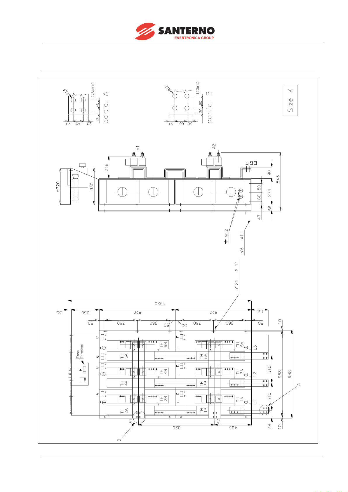
15P0059B3 DCREG2
USER MANUAL DCREG4
48/200
3.18 DCREG MODULAR.S SIZE K POWER SECTION OVERALL
DIMENSIONS

DCREG2 15P0059B3
DCREG4 USER MANUAL
49/200
3.19 DCREG MODULAR.S SIZE L POWER SECTION OVERALL
DIMENSIONS

15P0059B3 DCREG2
USER MANUAL DCREG4
50/200
3.20 DCREG MODULAR.S CONTROL UNIT OVERALL
DIMENSIONS

DCREG2 15P0059B3
DCREG4 USER MANUAL
51/200
3.21 DCREG SIZE 1...2A POWER CONNECTIONS
VALID FOR DCREG SIZE1...2A FOR MAINS UP TO 500 Vac

15P0059B3 DCREG2
USER MANUAL DCREG4
52/200
VALID FOR DCREG SIZE 1...2A FOR MAINS EXCEEDING 500 Vac

DCREG2 15P0059B3
DCREG4 USER MANUAL
53/200
3.22 DCREG MODULAR.S POWER CONNECTIONS
VALID FOR DCREG MODULAR.S FOR MAINS UP TO 500 Vac
NOTE
(*) Supply term. 53-54 with AC voltage OR term. 44-42 with DC voltage.
(*) VEDI NOTA
(SEE NOTE)

15P0059B3 DCREG2
USER MANUAL DCREG4
54/200
VALID FOR DCREG MODULAR.S FOR MAINS EXCEEDING 500 Vac
NOTE
(*) Supply term. 53-54 with AC voltage OR term. 44-42 with DC voltage.
(*) VEDI NOTA
(SEE NOTE)

DCREG2 15P0059B3
DCREG4 USER MANUAL
55/200
3.23 DCREG MODULAR.S POWER UNIT WIRING DIAGRAM
TH2A
TH2B
TH1A
TH1B
L1
L2
TH3A
TH3B
TH4B
TH4A
L3
TH5A
TH5B
TH6B
TH6A
A1
+(-)
-(+)
A2
NOTE
TH1B ... 6B thyristors (4 quadrants operation) in DCREG4 only.

15P0059B3 DCREG2
USER MANUAL DCREG4
56/200
3.24 DCREG MODULAR.S CONTROL UNIT TERMINALS
Decisive voltage class C according to EN 61800-5-1
G1A A bridge TH1 thyristor gate (to terminal G1A of the Control Unit)
K1A A bridge TH1 thyristor cathode (to terminal K1A of the Control Unit)
G2A A bridge TH2 thyristor gate (to terminal G2A of the Control Unit)
K2A A bridge TH2 thyristor cathode (to terminal K2A of the Control Unit)
G3A A bridge TH3 thyristor gate (to terminal G3A of the Control Unit)
K3A A bridge TH3 thyristor cathode (to terminal K3A of the Control Unit)
G4A A bridge TH4 thyristor gate (to terminal G4A of the Control Unit)
K4A A bridge TH4 thyristor cathode (to terminal K4A of the Control Unit)
G5A A bridge TH5 thyristor gate (to terminal G5A of the Control Unit)
K5A A bridge TH5 thyristor cathode (to terminal K5A of the Control Unit)
G6A A bridge TH6 thyristor gate (to terminal G6A of the Control Unit)
K6A A bridge TH6 thyristor cathode (to terminal K6A of the Control Unit)
G1B B bridge TH1 thyristor gate (to terminal G1B of the Control Unit)
K1B B bridge TH1 thyristor cathode (to terminal K1B of the Control Unit)
G2B B bridge TH2 thyristor gate (to terminal G2B of the Control Unit)
K2B B bridge TH2 thyristor cathode (to terminal K2B of the Control Unit)
G3B B bridge TH3 thyristor gate (to terminal G3B of the Control Unit)
K3B B bridge TH3 thyristor cathode (to terminal K3B of the Control Unit)
G4B B bridge TH4 thyristor gate (to terminal G4B of the Control Unit)
K4B B bridge TH4 thyristor cathode (to terminal K4B of the Control Unit)
G5B B bridge TH5 thyristor gate (to terminal G5B of the Control Unit)
K5B B bridge TH5 thyristor cathode (to terminal K5B of the Control Unit)
G6B B bridge TH6 thyristor gate (to terminal G6B of the Control Unit)
K6B B bridge TH6 thyristor cathode (to terminal K6B of the Control Unit)
Decisive voltage class A according to EN 61800-5-1
P0 Thermo-switches series common (to terminal P0 of the Control Unit)
PT Thermo-switches series NC (to terminal PT of the Control Unit)
Decisive voltage class C according to EN 61800-5-1
L1 L1 bar potential (Note 1)
L2 L2 bar potential (Note 1)
L3 L3 bar potential (Note 1)
A1 A1 bar potential (to terminal A1 of the Control Unit)
A2 A2 bar potential (to terminal A2 of the Control Unit)
Decisive voltage class A according to EN 61800-5-1
COM Current transformers common (to terminal COM of the Control Unit)
TAR TAR current transformer output (to terminal TAR of the Control Unit)
TAT TAT current transformer output (to terminal TAT of the Control Unit)
N.B.: TH1B .. 6B thyristors in DCREG4 type only.
(1) Note: Terminals L1-L2-L3 in the Control Unit are to be respectively connected to terminals L1-L2-
L3 in the Power Unit in case of a mains up to 500 Vac, whereas they have to be directly
connected to the secondary in three-phase transformer TS in case of a mains exceeding 500
Vac. In the latter case, terminals L1-L2-L3 in the Power Unit have to be left disconnected.

DCREG2 15P0059B3
DCREG4 USER MANUAL
57/200
3.25 SUPPLY AND POWER TERMINALS
Terminal
Description
Notes
L1
L2
L3
Input bars for armature rectifier
three-phase bridge power supply.
Decisive voltage class C according to EN 61800-5-1
Standard 440 Vac max
Electrical connection:
DCREG Size 1: 3xM8 (screw torque: 16 Nm / 142 lb/in)
DCREG Size 2: 3xM10 (screw torque: 25 Nm / 221 lb/in)
DCREG Size 2A: 3xM12 (screw torque: 40 Nm / 354 lb/in)
DCREG MODULAR.S:
see Power Section Overall Dimensions (See Note (1)
below)
A1
A2
Direct current output bars for motor
armature DC power supply.
Positive potential on bar A1
compared to bar A2, with positive
speed reference and drive not in
regeneration state.
Decisive voltage class C according to EN 61800-5-1
Standard 600 Vdc for DCREG2, 520 Vdc per DCREG4
Electrical connection:
DCREG Size 1: 3xM8 (screw torque: 16 Nm / 142 lb/in)
DCREG Size 2: 3xM10 (screw torque: 25 Nm / 221 lb/in)
DCREG Size 2A: 3xM12 (screw torque: 40 Nm / 354 lb/in)
DCREG MODULAR.S:
see Power Section Overall Dimensions (See Note (1)
below)
E1
E2
Input for field single-phase bridge
power supply.
Decisive voltage class C according to EN 61800-5-1
Standard 200 … 500 Vac
DCREG.100max: 5 A max, DCREG.150min Size 1: 15 A
max (screw torque: 2.53 Nm / 2227 lb/in)
DCREG Size 2(A) and MODULAR.S: 35 A max (See Note
(1) below)
F1
F2
Direct voltage output for motor field
DC power supply.
Positive potential on terminal F1
compared to terminal F2.
Decisive voltage class C according to EN 61800-5-1
Standard 425 Vdc max
DCREG.100max: 5 A max, DCREG.150min Size 1: 15A
max screw torque: 2.53 Nm / 2227 lb/in)
DCREG Size 2(A) and MODULAR.S: 35 A max (See Note
(1) below)
PV1
PV2
Cooling fans alarm relay contact.
Available on DCREG MODULAR.S only
To be introduced in external sequence for any alarm signal
1F
2F
Internal ultrafast fuses microswitches series.
Available on DCREG MODULAR.S only
To be introduced in external sequence for any alarm signal
42
44
Input for control section from 24
Vdc direct voltage.
Positive potential on terminal 44
compared to terminal 42.
Decisive voltage class A according to EN 61800-5-1
24 Vdc, 1.8A max (screw torque: 0.5 Nm / 4.4 lb/in)
51-52
(AV1-
AV2)
Single-phase alternating voltage
input for cooling fans power supply.
Note: not available for DCREG
Size 1-2.
Decisive voltage class C according to EN 61800-5-1
DCREG Size 2A: 230 Vac, 1.5 A
DCREG MODULAR.S: 230 Vac, 1.3 A max (See Note (1)
below)
53
54
Input for control section power
supply from single-phase
alternating voltage.
Decisive voltage class C according to EN 61800-5-1
Standard 380 … 500V ac. (See Note (2) below)
(screw torque: 0.40.6 Nm / 3.5-5.3 lb/in) (See Note (1)
below)
55
56
57
Input for synchronizing phases
from TS transformer secondary.
N.B.: terminals available on
DCREG Size 1 ... 2A only, for
supply mains higher than 500 Vac.
Decisive voltage class C according to EN 61800-5-1
500 Vac max (See Note (1) below)

15P0059B3 DCREG2
USER MANUAL DCREG4
58/200
Note (1): For UL application field use “75 °C copper wire only” or equivalent.
Note (2): If the control section is to be supplied with a single-phase alternating voltage, the max.
voltage to be applied to terminals 53-54 is 500 Vac. For the mains up to 690 Vac,
ELETTRONICA SANTERNO may supply a single-phase, 700/500 V transformer, 150 VA,
P/N TR0112260.

DCREG2 15P0059B3
DCREG4 USER MANUAL
59/200
3.26 LEGEND FOR POWER CONNECTIONS
A(B) AC/DC conversion bridge.
N.B.: for DCREG2, the polarities in brackets for bars A1 and A2 refer to the regenerative
operation.
CU Control unit for DCREG MODULAR.S.
FU1-2-3 Ultrafast fuses for DCREG Size 1... 2A.
Fast-acting fuses for DCREG MODULAR.S: in this case, fuses can be replaced by an
automatic circuit breaker.
FU4 Direct current side ultrafast fuse for AC/DC bridge protection.
N.B.: This is required for DCREG2 Size 1 ... 2A for regenerative operation only, and for
DCREG4 Size 1 ... 2A.
FU5-6 Ultrafast fuses protecting the field half-controlled rectifier bridge.
FU8-9 1A fast-acting fuses protecting the connection to terminals 53/54 to the power supply
mains.
FU10-11 2.5A fuses for DCREG Size 2A and DCREG MODULAR.S only, for air-cooling unit.
FU12 2.5A fast-acting fuses for internal switching.
FU13-14-15 1A delay fuses over transformer TS primary.
FU16-17-18 1A delay fuses over transformer TS secondary.
N.B.: they are required for DCREG Size 1 … 2A only and for a power supply exceeding
500 Vac.
KM AC/DC bridge power supply contactor.
In case of DCREG MODULAR.S, contactor can be replaced by an automatic circuit
breaker.
L Switching three-phase impedance.
L1-2-3 50/60 Hz three-phase mains.
M Direct current motor (armature circuit + field circuit).
PU DCREG MODULAR.S power unit.
TS Three-phase 50VA 700/500V transformer: phase shift 0°.
ELETTRONICA SANTERNO P/N: TR0108007.
N.B.: This is required for power supply values exceeding 500 Vac.

15P0059B3 DCREG2
USER MANUAL DCREG4
60/200
NOTE
Whenever requested, it is recommended to use ULTRAFAST FUSES of
the same type and value indicated in the RATINGS tables, so as to avoid
possible damages of the converter.
NOTE
Always install a three-phase remote control switch on the A.C. side,
together with a suitable NO auxiliary contact directly in the terminal 24
(ENABLE) series, as indicated in the SIGNAL CONNECTIONS diagram.
Do not connect other single-phase or three-phase loads in parallel to
bars L1, L2, L3, since the remote control switch should only supply the
above mentioned bars through the three-phase impedance.
NOTE
DO NOT OPEN the remote control switch during the braking phase with
regeneration towards the mains.
NOTE
To optimise the rotation stability on a DCREG4-type converter, it is
recommended to disable the possible STABILIZATION SERIES which
has been fit on the motor winding.

DCREG2 15P0059B3
DCREG4 USER MANUAL
61/200
3.27 CROSS-SECTIONS OF THE POWER CABLES AND SIZES
OF THE PROTECTIVE DEVICES
The minimum requirements of the power cables and the protective devices needed to protect the
system against short-circuits are given in the tables below. It is however recommended that the applicable
regulations in force be observed; also check if voltage drops occur for cable links longer than 100 m.
For the largest sizes of DCREG, special links with multiple conductors are provided for each
phase. For example, 2x120 in the column relating to the cable cross-section means that two 120 mm2
parallel conductors are required for each phase.
Multiple conductors shall have the same length and must run parallel to each other, thus ensuring
even current delivery at any frequency value. Paths having the same length but a different shape deliver
uneven current at high frequency.
Also, do not exceed the screw torque for the terminals to the bar connections. For connections to
bars, the screw torque relates to the bolt tightening the cable lug to the copper bar. The cross-section
values given in the tables below apply to copper cables.
The links between the motor and the DCREG drive must have the same length and must follow
the same paths.
Size
DCREG2
DCREG4
Model
Eyelet terminal
Screw
torque
Cable Cross-section to
AC and DC Side
Ultrafast fuses
AC Side
Ultrafast fuses
DC Side
AC1
Contactor
AC Side
Nm / lb/in
mm2
(AWG/kcmils)
A
A
A (model)
1
.10
M8
16 / 142
2.5 (12AWG)
See RATINGS
tables
See RATINGS
tables
25 (AF09)
.20
4 (10AWG)
25 (AF09)
.40
10 (6AWG)
50 (AF30)
.70
25 (4AWG)
100 (AF52)
.100
50 (1/0AWG)
125 (AF80)
.150
70 (2/0AWG)
200 (AF140)
.180
95 (4/0AWG)
225 (AF146)
.250
120 (250kcmils)
275 (AF190)
.350
2x120 (2x250kcmils)
400 (AF265)
2
.410
M10
25 / 221
2x120 (2x250kcmils)
500 (AF305)
.500
2x185 (2x350kcmils)
600 (AF400)
.600
2x240 (2x500kcmils)
700 (AF460)
.900
3x240 (3x500kcmils)
1050 (AF750)
2A
.1200
M12
40 / 354
4x240 (4x500kcmils)
1650 (AF1650)
CAUTION
Always use the correct cable cross-sections and activate the protective
devices provided for DCREG. Failure to do so will cause the noncompliance to standard regulations of the system where the DCREG is
installed.
CAUTION
Additional UL requirements: for the North American market, a 600 Vac
cable is accepted for up to 500 Vac. A 1000 Vac cable is required above
500 Vac (below 600 Vac).
The power cables must be rated for 75 °C (167 °F).
NOTE
For details on wiring and safety devices for a DCREG MODULAR.S please
contact Elettronica Santerno.

15P0059B3 DCREG2
USER MANUAL DCREG4
62/200
3.28 SWITCHING THREE-PHASE INDUCTANCE
A three-phase inductance is to be inserted into the power supply line. The inductance is aimed at:
- Reducing the mains voltage distortions from the sinusoidal form in the drive connecting point.
- Reducing the line current gradients which may cause both radio interferences and induced interferences
in the close lines.
Two series of three-phase inductances are available, named L2 and L4.
They have a different inductance value, i.e. a different phase drop (approx. 6V for the L2-type and 1V for
the L4-type): L2-type shows a better performance than L4-type.
The table below shows the inductance specifications depending on the converter size and by referring to
the power supply voltage values to be applied.
Drive size
INDUCTANCE
L2 @ 500V TYPE
INDUCTANCE
L2 @ 600-690V TYPE
INDUCTANCE
L4 TYPE
P/N
P/N
P/N
DCREG.10
IM0126004 - 2000H
IM0127004 - 3451H
3 x IM0100354 - 150H
DCREG.20
IM0126044 - 1273H
IM0127044 - 2196H
3 x IM0100354 - 150H
DCREG.40
IM0126084 - 700H
IM0127084 - 1208H
3 x IM0100354 - 150H
DCREG.70
IM0126164 - 239H
IM0127164 - 412H
IM0122104 - 45H
DCREG.100
IM0126164 - 239H
IM0127164 - 412H
IM0122154 - 30H
DCREG.150
IM0126204 - 156H
IM0127204 - 268H
IM0122154 - 30H
DCREG.180
IM0126244 - 88H
IM0127244 - 151H
IM0122204 - 20H
DCREG.250
IM0126244 - 88H
IM0127244 - 151H
IM0122254 - 15H
DCREG.350
IM0126284 - 61H
IM0127284 - 105H
IM0122304 - 10H
DCREG.410
IM0126284 - 61H
IM0127284 - 105H
IM0122304 - 10H
DCREG.500
IM0126324 - 54H
IM0127324 - 93H
IM0122404 - 6.2H
DCREG.600
IM0126364 - 33H
IM0127364 - 58H
IM0122404 - 6.2H
DCREG.750
-
IM0127364 - 58H
IM0122504 - 4.5H
DCREG.900
IM0126404 - 23H
IM0127404 - 40H
IM0122504 - 4.5H
DCREG.1050
-
IM0127404 - 40H
IM0122604 - 3H
DCREG.1200
IM0126404 - 23H
-
IM0122604 - 3H
DCREG.1250
-
IM0127444 - 30H
IM0122604 - 3H
DCREG.1400
IM0126444 - 18H
-
IM0122704 - 2.5H
DCREG.1600
IM0126444 - 18H
IM0127444 - 30H
IM0122704 - 2.5H
DCREG.1800
IM0126484 - 11H
IM0127484 - 18H
IM0122804 - 1.6H
DCREG.2000
IM0126484 - 11H
IM0127484 - 18H
IM0122804 - 1.6H
DCREG.2300
IM0126484 - 11H
IM0127484 - 18H
IM0122804 - 1.6H
DCREG.2500
IM0126484 - 11H
IM0127484 - 18H
IM0122804 - 1.6H
DCREG.2700
IM0126524 - 8H
IM0127524 - 13H
IM0122904 - 1.1H
DCREG.3000
IM0126524 - 8H
IM0127524 - 13H
IM0122904 - 1.1H
DCREG.3500
IM0126524 - 8H
IM0127524 - 13H
IM0122904 - 1.1H
DCREG.4500 - -
-

DCREG2 15P0059B3
DCREG4 USER MANUAL
63/200
3.29 UL-APPROVED FUSES
UL-approved semiconductor R/C Special purpose fuses which are recommended for the DCREG drives,
are listed in the table below.
In multiple cable installations, install one fuse per phase (NOT one fuse per conductor).
Fuses suitable for the protection of semiconductors produced by other manufacturers may be used,
provided that:
• Their current ratings are lower than or equal to those listed in the table below;
• Their voltage ratings are higher than or equal to those listed in the table below;
• are nonrenewable UL-Listed Cartridge Fuses (UL Category P/N JFHR2) or UL Recognized
External Semiconductor Fuses;
• are of the type specifically approved also with reference to the Canadian Standard (UL Category
P/N JFHR8).
NOTE
Listed Class CC fuses are provided in the supply line to control card and field
supply terminals.
Fuse ratings shall be as indicated below:
Control Card Supply Fuses – maximum 1 A, minimum 500 Vac.
Field Supply Fuses – maximum 20 A, minimum 500 Vac.
DCREG Model
UL-approved Fuses Manufactured by:
SIBA Sicherungen-Bau GmbH
(200 kA
RMS
Symmetrical A.I.C.)
Bussmann Div Cooper (UK) Ltd
(100/200 kA
RMS
Symmetrical A.I.C.)
Mod. No.
Ratings
Mod. No.
Ratings
Current
Arms
Voltage Vac
Current
Arms
Voltage
Vac
DCREG.10
50 154 06.20
20
700
170M1410
20
700
DCREG.20
50 154 06.20
20
170M1410
20
DCREG.40
20 412 20.40
40
170M1413
40
DCREG.70
20 412 20.80
80
170M1416
80
DCREG.100
20 412 20.100
100
170M2664
100
DCREG.150
20 412 20.160
160
170M2666
160
DCREG.180
20 412 20.160
160
170M2666
160
DCREG.250
20 412 20.250
250
170M2668
250
DCREG.350
20 412 20.315
315
170M2669
315

15P0059B3 DCREG2
USER MANUAL DCREG4
64/200
3.30 SHORT-CIRCUIT CURRENT
The Short Circuit Current is referred to the maximum converter power. All the converter models are rated
for Standard Fault Current values in accordance with UL508C and based on an Internal Solid State Short
Circuit protection whose operation and whose manufacturing process complies with UL508C.
Model
Input
Output
DCREG2
max
Voltage
[Vac]
Current
[A]
max
Voltage
[Vdc]
Current
[A]
max
Power
[kW]
max
Power
[HP]
SCCR
[kA rms]
.10
500
8.2
600
10
6
8.0
5
.20
16.4
20
12
16.1
.40
33
40
24
32.2
.70
57
70
42
56.3
10
.100
82
100
60
80.5
.150
123
150
90
120.7
.180
148
180
108
144.8
.250
205
250
150
201.2
18
.350
287
350
210
281.6
DCREG4
max
Voltage
[Vac]
Current
[A]
max
Voltage
[Vdc]
Current
[A]
max
Power
[kW]
max
Power
[HP]
SCCR
[kA rms]
.10
500
8.2
520
10
5.2
7.0
5
.20
16.4
20
10.4
13.9
.40
33
40
20.8
27.9
.70
57
70
36.4
48.8
.100
82
100
52
69.7
10
.150
123
150
78
104.6
.180
148
180
93.6
125.5
.250
205
250
130
174.3
.350
287
350
182
244.1
18
Model
Input
Output
DCREG2
max
Voltage
[Vac]
Current
[A]
max
Voltage
[Vdc]
Current
[A]
max
Power
[kW]
max
Power
[HP]
SCCR
[kA rms]
.10
600
8.2
720
10
7.2
9.7
5
.20
16.4
20
14.4
19.3
.40
33
40
28.8
38.6
.70
57
70
50.4
67.6
10
.100
82
100
72
96.6
.150
123
150
108
144.8
.180
148
180
129.6
173.8
.250
205
250
180
241.4
18
.350
287
350
252
337.9
DCREG4
max
Voltage
[Vac]
Current
[A]
max
Voltage
[Vdc]
Current
[A]
max
Power
[kW]
max
Power
[HP]
SCCR
[kA rms]
.10
600
8.2
630
10
6.3
8.4
5
.20
16.4
20
12.6
16.9
.40
33
40
25.2
33.8
.70
57
70
44.1
59.1
10
.100
82
100
63
84.5
.150
123
150
94.5
126.7
.180
148
180
113.4
152.1
.250
205
250
157.5
211.2
18
.350
287
350
220.5
295.7

DCREG2 15P0059B3
DCREG4 USER MANUAL
65/200
3.31 CONVERTER AND MOTOR GROUND CONNECTION
A bolted screw for the converter enclosure grounding is located close to the power wiring terminals. The
grounding screw is identified by the symbol below:
Always ground the DCREG to a state-of-the-art mains. To reduce disturbance and radiated interference to
a minimum, connect the motor grounding conductor directly to the DCREG following a parallel path to the
motor supply cables.
DANGER
Always connect the converter grounding terminal to the grid grounding using a
conductor complying with the safety regulations in force (see table below).
Always connect the motor casing to the converter grounding to avoid dangerous
voltage peaks and electric shock hazard.
Always provide a proper grounding of the converter frame and the motor casing.
DANGER
The touch current in the ground protective conductor exceeds 3.5 mAac/10 mAdc.
Please refer to the table below for the dimensioning of the protective conductors.
NOTE
To fulfil UL conformity requirements of the system where the converter is installed,
use a “UL R/C” or “UL Listed” lug to connect the converter to the grounding
system. Use a loop lug fitting the ground screw and having the same cross-section
as the ground cable being used.
Protective earthing conductor cross-section (refer to EN 61800-5-1):
Cross-sectional area of phase
conductors
of the converter (mm2)
Minimum cross-sectional area of the
corresponding
protective earthing conductor (mm2)
S ≤ 10
10 (*)
10 < S ≤ 16
S (*)
16 < S ≤ 35
16
35 < S
S/2
NOTE
The values in the table above are valid only if the protective earthing conductor is
made of the same metal as the phase conductors.
If this is not so, the cross-sectional area of the protective earthing conductor shall
be determined in a manner which produces a conductance equivalent to that which
results from the application of the table above.
NOTE (*)
In any case, a cross-section of the protective earthing conductor of at least 10
mm
2
Cu or 16 mm2 Al is required to maintain safety in case of damage to or
disconnection of the protective earthing conductor (refer to EN 61800-5-1 about
Touch current).

15P0059B3 DCREG2
USER MANUAL DCREG4
66/200
3.32 DCREG SIGNAL CONNECTIONS
DCREG2: for
standard usage, supply
the potentiometer
between term. 1 and 2

DCREG2 15P0059B3
DCREG4 USER MANUAL
67/200
3.33 SIGNAL TERMINALS
Decisive voltage class A according to EN 61800-5-1 (except for the cases specified below)
TERM.
Description
I/O Ratings
1
+10V: +10V reference voltage output for analog inputs.
+10 Vdc / 10 mA max
2
0V: Zerovolt.
-
3
-10V: -10V reference voltage output for analog inputs.
-10 Vdc / 10 mA max
4
n OUT: Speed signal output for tachometer or any other use. Positive
polarity with bridge A running (not in regenerative state).
The value 10V corresponds to the max. speed (voltage) feedback signal, i.e.
parameter M001 (nFdbk) is equal to 100%.
If the drive is in armature feedback mode, this output is not enabled.
-10 … +10 Vdc
5 mA max
5-7
REF: Main analog input (5: REF+ / 7: REF-).
If both signal wires are connected, the two terminals represent a differential input
with a high rejection to interferences. Alternatively, with a signal to be reflected to
the drive 0V, the two terminals represent a common mode input. This common
mode input is a non-reversing input if the signal “hot wire” is connected to terminal
5 when terminal 7 is disconnected, whereas it is a reversing input if it is connected
to terminal 7 when terminal 5 is disconnected.
By setting jumper JP407 in the control board on pos. 2-3, the two terminals will
represent an input for a signal expressed in milliAmperes: a positive reference is
generated if the current enters terminal 5 and goes out through terminal 7. See
also the MILLIAMPERE INPUT / OUTPUT SIGNALS chapter.
JP407 on pos. 1-2:
-10 … +10 Vdc
Rin = 20 k
JP407 on pos. 2-3:
20 mA max
Rin = 200
6
I OUT: Current signal output (filtered) for possible ammeter, or different use.
Positive polarity with bridge A in operation. The value is 6.67V according to
the rated current of the drive (i.e. 100A for a DCREG.100).
In case of a DCREG4, the mentioned signal can be set as bipolar or
unipolar by means of the parameter P156 (IOutPol).
-10 ... +10 Vdc
8
OUT 1: Analog output 1 to be configured with parameter P150
(AnOut1Cfg).
By setting jumper JP4010 in the control board on pos. 1-2, the terminal
will represent an output for a voltage signal, while when the jumper is
set on pos. 2-3, the term inal will represent an output f or a s ignal
expressed in milliAmperes. An outgoing current only may be produced
towards 0V potential. See also the MILLIAMPERE INPUT / OUTPUT
SIGNALS chapter.
JP4010 on pos. 1-2:
-10 ... +10 Vdc
5 mA max
JP4010 on pos. 2-3:
0 ... 20 mA
10 V max
9
0V: Zerovolt.
-
10
OUT 2: Analog output 2 to be configured through parameter P153 (AnOut2Cfg).
By setting jumper JP409 in the control board on pos. 1-2, the terminal will
represent an output for a voltage signal, while when the jumper is set on pos. 2-3,
the terminal will represent an output for a signal expressed in milliAmperes. An
outgoing current only may be produced towards 0V potential. See also the
MILLIAMPERE INPUT / OUTPUT SIGNALS chapter.
JP409 on pos. 1-2:
-10 ... +10 Vdc
5 mA max
JP409 on pos. 2-3:
0 ... 20 mA
10 V max
11-13
IN 1: Analog input 1 (11: IN 1+ / 13: IN 1-) to be configured through
parameter C120 (AnIn1Cfg). If both signal wires are connected, the two
terminals represent a differential input with a high rejection to interferences.
Alternatively, with a signal to be reflected to the drive 0V, the two terminals
represent a common mode input. This common mode input is a non-
reversing input if the signal “hot wire” is connected to terminal 11 when
terminal 13 is disconnected, whereas it is a reversing input if it is connected
to terminal 13 when terminal 11 is disconnected.
By setting jumper JP408 in the control board on pos. 2-3, the two terminals
will represent an input for a signal expressed in Milliamperes: a positive
reference is generated if the current enters terminal 11 and goes out
through terminal 13. See also the MILLIAMPERE INPUT / OUTPUT
SIGNALS chapter.
JP408 on pos. 1-2:
-10 … +10 Vdc
Rin = 20 k
JP408 on pos. 2-3:
20 mA max
Rin = 200

15P0059B3 DCREG2
USER MANUAL DCREG4
68/200
TERM.
Description
I/O Ratings
12
CH N: Zero position pulse of the enP/Nr.
-
14
CH A: Channel A of the enP/Nr.
102.4 k Hz max
15
+5V: +5V mains supply voltage for the enP/Nr. It is optoinsulated from the 0V
signal of analog inputs.
+5 Vdc
160 mA max
16
CH B: Channel B of the enP/Nr.
102.4 k Hz max
17
IN 2: Analog input 2 to be configured through parameter C121(AnIn2Cfg).
-10 … +10 Vdc
20 mA max
Rin = 20 k
18
0V: Zerovolt.
-
19
IN 3: Analog input 3 to be configured through parameter C122 (AnIn3Cfg).
-10 … +10 Vdc
Rin = 20 k
20
DT 25Vmax: Input for a tacho when it does not exceed the absolute value
equal to 25V. Polarity has to be a positive one with bridge A running (not in a
regenerative state).
-25 … +25 Vdc
Rin 5 k
21
0V: Zerovolt.
-
22
DT 80Vmax: Input for a tacho when it does not exceed the absolute value
equal to 80V. Polarity has to be a positive one with bridge A running (not in a
regenerative state).
Decisive voltage class B according to EN 61800-5-1
-80 … +80 Vdc
Rin 80 k
23
DT 250Vmax: Input for a tacho when it does not exceed the absolute value
equal to 250V. Polarity has to be a positive one with bridge A running (not in a
regenerative state).
Decisive voltage class C according to EN 61800-5-1
-250 … +250 Vdc
Rin 300 k
24
ENABLE: Drive operation command enabling. The signal is active when the
terminal is short-circuited with +24V (terminal 40). The contact related to this
terminal, shown in the SIGNAL CONNECTIONS diagram, consists of a NO
auxiliary contact of contactor KM energizing the drive power section.
See Note (*).
Iin 9 mA
25-27
MDO 1: Digital output 1 to be configured through parameter P170 (MDO1Cfg).
Default configuration: 0:Drive OK.
Decisive voltage class C according to EN 61800-5-1
5A / 250 Vac
5A / 30 Vdc
26
START: Enabling of the speed / voltage references or current references to be
found on analog inputs REF, IN 1, IN 2, IN 3 (summed up to the reference from
serial connection, field bus and UpDownRef internal variable), or enabling of
one of the run preset references. The signal is active when the terminal is
short-circuited with +24V (terminal 40). When the contact on terminal 26 opens,
a ramp down is set starting from the current speed / voltage signal. The ramp
down time is set in parameter P034 or P035. See RAMPS OVER REFERENCE
chapter for the inequality relations assuring that the times set for the stop
ramps in par. P034 and P035 are exactly respected.
Iin 9 mA
28
MDI 1: Digital input 1 to be configured through parameter C130 (MDI1Cfg).
Default configuration: 0:Reset.
Iin 9 mA
29-31
MDO 2: Digital output 2 to be configured through parameter P176 (MDO2Cfg).
Default configuration: 1:SpeedThreshold.
Decisive voltage class C according to EN 61800-5-1
5A / 250 Vac
5A / 30 Vdc
30
MDI 2: Digital input 2 to be configured through parameter C131 (MDI2Cfg).
Default configuration: 12:JogA.
Iin 9 mA
32
MDI 3: Digital input 3 to be configured through parameter C132 (MDI3Cfg).
Default configuration: 13:JogB.
Iin 9 mA
33-35
MDO 3: Digital output 3 to be configured through parameter P182 (MDO3Cfg).
Default configuration: 2:Iarm Threshold.
Decisive voltage class C according to EN 61800-5-1
5A / 250 Vac
5A / 30 Vdc
34
MDI 4: Digital input 4 to be configured through parameter C133 (MDI4Cfg).
Default configuration: 1:Preset Speed A.
Iin 9 mA

DCREG2 15P0059B3
DCREG4 USER MANUAL
69/200
TERM.
Description
I/O Ratings
36
MDI 5: Digital input 5 to be configured through parameter C134 (MDI5Cfg).
Default configuration: 4:Clim.
Iin 9 mA
37-39
MDO 4: Digital output 4 to be configured through parameter P188 (MDO4Cfg).
Default configuration: 5:Drive Running.
Decisive voltage class C according to EN 61800-5-1
5A / 250 Vac
5A / 30 Vdc
38
MDI 6: Digital input 6 to be configured through parameter C135 (MDI6Cfg).
Default configuration: 5:Reverse.
Iin 9 mA
40
+24V (OPTO): +24V main voltage supply output for digital inputs operation
and/or to supply the enP/Nr. It is optoinsulated from the 0V signal of analog
inputs.
+24 Vdc
200 mA max
41-43
MDO 5: Digital output 5 to be configured through parameter P194 (MDO5Cfg).
Default configuration: 4:CurrLimitation.
Decisive voltage class C according to EN 61800-5-1
5A / 250 Vac
5A / 30 Vdc
42
0V(OPTO): Negative terminal of +24V external supply voltage (if any) to supply
the control section and/or the enP/Nr. It is optoinsulated from the 0V signal of
analog inputs. If the digital inputs come from the static outputs of a PLC, 0V of
the PLC is to be connected to this terminal.
-
44
+24V(EXT): Input for positive terminal of +24V external supply voltage to supply
the control section.
+24 Vdc / 2 A
max
Note (*)
1a DRIVE LOCK WHILE STOPPING.
Suppose C051 is set at 1:Predictive=>J1 value. In that case, even after the START contact to terminal 26
is open and the motor fall ramp is over, if the ENABLE contact to terminal 24 is kept closed, the drive
“regulates zero current” (no torque is generated), i.e. the drive is still operating, although the motor is
idling.
While the motor is not running (idling), if for some particular reasons contactor KM has to remain closed
for a long time, for the operator’s safety it is possible to wire an additional contact to terminal 24; such
contact is to be series connected to auxiliary contact NO of contactor KM. If this contact opens, the current
reference will be set to zero, and the drive will be disabled (motor idling, drive in stand-by).
On the other hand, in case parameter C051 is set at 0:PI operating, the drive will automatically inhibit any
firing pulse as soon as the motor down ramp is over. The motor keeps idling.
1b MOTOR NEUTRAL
If a rotating motor controlled by the drive is to be put in neutral, the contactor is recommended not to be
opened. First open the above-mentioned additional contact (which is to be previously wired to terminal 24,
series connected to auxiliary NO contact of contactor KM), then open contactor KM.
1c CLOSING THE ENABLE CONTACT WHEN THE MOTOR IS IDLING.
When the connected motor is idling and the ENABLE contact is closed but the START contact is open, the
system sets the ramp set for par. P034 (RampStopPos) or par. P035 (RampStopNeg) up to zero speed.
The connected motor keeps idling.

15P0059B3 DCREG2
USER MANUAL DCREG4
70/200
3.34 LEDS AND TEST POINTS ON THE CONTROL BOARD
The following is a list of visual indications provided by the LEDs installed on the control board. The voltage
values of the test points on the same board are also stated.
LEDs:
OP1 (green) S8 heatsink switch closed
OP5 (green) SA bridge A active
OP6 (yellow) SB bridge B active
OP7 (green) RUN drive running
OP8 (yellow) LIM drive in current limitation
OP27 (green) S0 Terminal 24 connected to +24V OPTO (ENABLE)
OP28 (green) S1 Terminal 26 connected to +24V OPTO (START)
OP29 (green) S2 Terminal 28 connected to +24V OPTO (MDI1)
OP30 (green) S3 Terminal 30 connected to +24V OPTO (MDI2)
OP31 (green) S4 Terminal 32 connected to +24V OPTO (MDI3)
OP32 (green) S5 Terminal 34 connected to +24V OPTO (MDI4)
OP33 (green) S6 Terminal 36 connected to +24V OPTO (MDI5)
OP34 (green) S7 Terminal 38 connected to +24V OPTO (MDI6)
OP35 (green) SC Contact at terminals 25-27 closed (MDO1)
OP36 (green) SD Contact at terminals 29-31 closed (MDO2)
OP37 (green) SE Contact at terminals 33-35 closed (MDO3)
OP38 (green) SF Contact at terminals 37-39 closed (MDO4)
OP39 (green) SG Contact at terminals 41-43 closed (MDO5)
OP40 (green) STX active serial transmission to keypad
TEST POINTS:
TS3 (dia 2.1) GND 0V
TS6 (dia 1.2) H0OUT armature current (+2.5V at 100%)
TS8 (dia 1.2) VAR armature voltage (0V … +5.0V with –665V … +665V)
TS9 (dia 1.2) VAC mains voltage (+3.0V approx. with 380 VAC)
TS36 (dia 2.1) GND 0V
TS38 (dia 1.2) AN0 tacho generator (±4.5V at 100%)
TS46 (dia 1.2) CHB channel B of enP/Nr (digital signal 0-5V)
TS47 (dia 1.2) CHA channel A of enP/Nr (digital signal 0-5V)
TS56 (dia 2.1) GND 0V
TS59 (dia 1.2) +5V +5V digital (referred to GND)
TS60 (dia 1.2) +5VOP +5V optoinsulated for enP/Nr (referred to OP)
TS61 (dia 1.2) OP 0V reference for +5VOP and +A
TS62 (dia 1.2) +A +24V optoinsulated (referred to OP)

DCREG2 15P0059B3
DCREG4 USER MANUAL
71/200
3.35 FEEDBACK FROM ENP/NR
For the enP/Nr connection, the following may be used:
1. The M1 screw double terminal board with 44 terminals.
2. The CN2 9-pole D-connector.
In both cases, all the available input channels and supply values are optoinsulated with respect to the
analog inputs potential. When choosing the enP/Nr type, check the max. speed frequency, that may be
obtained from the following formula
60
/
max
max
nrevpulses
f
, where pulse/rev is the enP/Nr number of
pulses for each complete rotation and n
max
is the max. rotation speed expressed in rev/min.
Using the screw terminal board.
In the first event the features of the enP/Nr to be connected are the following:
1a. Complementary push-pull enP/Nr or NPN-type or Open Collector
2a. High level of the output waveform on the three channels equal to 24 VDC max
3a. Input maximum frequency equal to 102.400k Hz (e.g. 1024 pulse/rev for 6000 RPM max.)
4a. 5 Vdc or 24 Vdc voltage available for enP/Nr supply through DCREG drive
The following terminals should be used:
14 - Input for channel A 15 - 5 VDC supply output
16 - Input for channel B 42 - 0V
12 - Input for channel N (1) 40 - 24 VDC supply output
The enP/Nr screened cable shield should be connected to the ground potential as directly as possible.
Use one of the 3 collar-shaped cable fasteners located on the bottom of the control board supporting
guard.
Using the D-connector.
In the second case the features of the enP/Nr to be connected are the following:
1a. Line-driver enP/Nr (RS422 output standard)
2a. High level of the output waveform on the six channels ranging from 5...15 Vdc
3a. Max. input frequency equal to 102.400k Hz (e.g. 1024 pulse/rev for 6000 RPM max)
4a. 5 Vdc or 24 Vdc enP/Nr supply through DCREG drive
The following D-connector pins should be used:
pin 1 - Input for channel A pin 6 - Input for channel N (1)
pin 2 - Input for channel A pin 7 - 5 VDC supply output
pin 3 - Input for channel B pin 8 - 0V
pin 4 - Input for channel B pin 9 - 24 VDC supply output
pin 5 - Input for channel N (1)
In this case, it is not necessary to use one of the three collar-shaped cable fasteners located on the
bottom of the control board supporting guard to connect the screened cable shield of the enP/Nr to the
ground potential, unless a screened 9-pole flying male connector is used. Said connector is to be
assembled inside a screening metal body:
ITT-CANNON mod. DE121073-154 (connector body) + n.2 250-8501-013 (pair of long fastening screws).
FRAMATONE mod. 8655 MH 09 01.
In that way, the ground potential on 90° female connector in the control board will be transmitted to the
metal body, then to the screened cable shield connecting the enP/Nr.
The connector body is supplied by ELETTRONICA SANTERNO (P/N CN0420000), as well as 9-pole Dconnector (P/N CN0400018).
(1) This is not required for the speed feedback, but is required for the position control.

15P0059B3 DCREG2
USER MANUAL DCREG4
72/200
3.36 MILLIAMPERE INPUT / OUTPUT SIGNALS
It is possible to feed an analog input as an mA signal to terminals 5 / 7 (REF) or terminals 11 / 13 (IN
1): if current enters terminal 5 and goes out from terminal 7, or if current enters terminal 11 and goes out
from terminal 13, the internally generated signal is positive by default.
Similarly, it is possible to obtain an analog output as an mA signal from terminal 8 (OUT 1) or terminal
10 (OUT 2): said signal, that may be only outgoing towards 0V, is obtained by an internally generated
signal which is positive by default.
1. INPUT SIGNALS
Between signal Iin in mA, which is externally applied, and signal VRLin Volt, which is internally generated in
the load resistance terminals, the following relation is applied:
Iin =20mA VRL =4V
The Gain and Bias functions (and the Polarity and Reverse following functions) may be applied to signal
VRL before generating the TermRef reference displayed by parameter M014 (or signal AnIn1 displayed by
parameter M010), according to the formula below:
100
10
100
)1(Re
BiasGain
VAnInfTerm
RL
With the default values of the relevant parameters, the final matching between Iin and TermRef(AnIn1) is
the following:
Iin =0mA TermRef(AnIn1)=0V
Iin =4mA TermRef(AnIn1)=0.8V
Iin =20mA TermRef(AnIn1)=4V
The table below shows the values to be assigned to the different parameters relating to the Gain and Bias
functions in order to obtain a given percentage of internal reference TermRef(AnIn1), with 100%
corresponding to 10V, starting from external signal Iin in mA. The table assumes that the parameters
relating to the Polarity function (parameter P120 and P126) are at their default value and that the Reverse
function is not applied.
Iin M014 (M010)
Jumper JP407
in the control board
in pos. 2-3
Jumper JP408
in the control board
in pos. 2-3
REF [Terminals 5 / 7]
Speed / voltage reference
REF [Terminals 5 / 7]
Armature current reference
IN 1 [Terminals 11 / 13]
Gain
Bias
Gain
Bias
Gain
Bias
0...20mA 0...+100%
P122=250%
P121=0%
P125=250%
P124=0%
P128=250%
P127=0%
0...20mA –100%...+100%
P122=500%
P121=–100%
P125=500%
P124=–100%
P128=500%
P127=–100%
4...20mA 0...+100%
P122=312.5%
P121=–25%
P125=312.5%
P124=–25%
P128=312.5%
P127=–25%
4...20mA –100%...+100%
P122=625%
P121=–150%
P125=625%
P124=–150%
P128=625%
P127=–150%
2. OUTPUT SIGNALS

DCREG2 15P0059B3
DCREG4 USER MANUAL
73/200
Between signal AnOut1(2) in Volt, which is internally generated after configuring analog output OUT 1 or
OUT 2 as desired and which is displayed by parameters M019 and M020 respectively, and outgoing signal
I
out
in mA, the following relation is to be applied:
AnOut1(2)=10V I
out
=20mA
Before generating signal AnOut1(2), the Gain and Bias functions may be used (followed by the Polarity
function) starting from signals V
out1(2)
originally configured, according to the formula below:
100
10
100
BiasGain
VAnOut
out
With the default values of the relevant parameters, the final matching between V
out
and I
out
is the following:
V
out
=0V I
out
=0mA
V
out
=2V I
out
=4mA
V
out
=10V I
out
=20mA
The table below shows the values to be assigned to the different parameters relating to the Gain and Bias
functions to obtain a particular signal I
out
in mA, starting from internal signal V
out
in Volt. The table
assumes that the parameters relating to the Polarity function (par. P157 and P158) are at their default
value.
V
out
I
out
Jumper JP4010
in the control board
in pos. 2-3
Jumper JP409
in the control board
in pos. 2-3
OUT 1 [Terminal 8]
OUT 2 [Terminal 10]
Gain
Bias
Gain
Bias
0 ... 10V 0 ... 20mA
P152 = 100%
P151 = 0%
P155 = 100%
P154 = 0%
0 ... 10V 4 ... 20mA
P152 = 80%
P151 = 20%
P155 = 80%
P154 = 20%
–10 ... +10V 0 ... 20mA
P152 = 50%
P151 = 50%
P155 = 50%
P154 = 50%
–10 ... +10V 4 ... 20mA
P152 = 40%
P151 = 60%
P155 = 40%
P154 = 60%

15P0059B3 DCREG2
USER MANUAL DCREG4
74/200
4 KEYPAD AND ALPHANUMERIC DISPLAY
4.1 KEYS OPERATING MODES
The drives of the DCREG2 and DCREG4 Series may be equipped with a remotable keypad provided with
an alphanumeric display, including 8 keys and 8 signalling LEDs.
NOTE
The keypad is not series installed on the drive and is to be delivered
separately. The remotable keypad kit is to be ordered for the keypad
assembly on a separate panel: see the REMOTABLE KEYPAD chapter.
The 2-line 16-digit backlit LCD display installed in the keypad shows the parameter values, the diagnostic
messages and the values of the quantities processed by the drive. From now on, the term “page”
indicates the 32 characters that are simultaneously displayed.
The eight keys have the following functions:
- “PROG”: allows to switch from display mode (fixed cursor) to programming mode (blinking cursor) and
vice versa. So when the cursor is fixed, you may use the scrolling keys to display the different parameters
in sequence. When the cursor is blinking, you may change the value of the current parameter.
- “
” (“DEC”): allows to decrease either the page number or the value displayed inside the current page,
depending on which mode you selected with the “PROG” key, i.e. depending on the cursor state.
- “
” (“INC”): allows to increase either the page number or the value displayed inside the current page,
depending on which mode you selected with the “PROG” key, i.e. depending on the cursor state.
- “SAVE”: in programming mode only, it saves the current value on the page displayed on non-volatile
memory work area (EEPROM), so that the value is kept stored even after turning the drive off and is
displayed at next power on.

DCREG2 15P0059B3
DCREG4 USER MANUAL
75/200
- “JOG”: is active only when at least one of the sources selected for the commands corresponds to
KeyPad and, when depressed, it enables the jog mode with a reference equal to the one obtained by
enabling digital input JogA.
- “
REVERSE
FORWARD
”: is active only when at least one of the sources selected for the commands corresponds
to KeyPad, and when depressed, it enables the polarity reversal of the Ref n reference applied to the
ramps.
- “START”: is active only when at least one of the sources selected for the commands corresponds to
KeyPad and, when depressed, it enables a self-retained run command, with a reference equal to the one
obtained by enabling the START digital input. For the interaction of this key with the START digital inputs
coming from other sources, refer to the Ref n section in the BLOCK DIAGRAM chapter.
- “STOP”: in general, it is active only when at least one of the sources selected for the commands
corresponds to KeyPad and, when depressed, it enables a stop command, just as if digital input START
was disabled. For the interaction of this key with the START digital inputs coming from other sources,
refer to the Ref n section in the BLOCK DIAGRAM chapter. In addition, even though none of the sources
selected for the commands corresponds to KeyPad, this key may have the STOP function by setting par.
C103 (EmergStop) to 0:Included.
NOTE
When operating, the drive uses the current parameter set, i.e. the parameters
available at the moment. The parameter that has been updated with the “
”
and “” keys will be immediately used instead of the previous parameter,
even if it is not saved with the “SAVE” key. The new value will not obviously be
stored when the drive is turned off.
For a simpler use of the drive, the following command shortcuts are available:
- ALARM RESET: Press the “PROG” and “SAVE” keys simultaneously to close a digital input
configured as 0:Reset for an alarm reset. Of course, the alarm will be cancelled once the cause
responsible for its trip has disappeared.
- QUICK PAGE SHIFT (MONITOR function): Press the “
” and “
” keys simultaneously to access
the page relating to parameter P000 (Key). Press “
” and “
” again to access the Keypad page relating
to parameter M000 (Vref) and to other measure parameters selected through parameter P005 (FirstParm)
and P006 (MeasureSel). Press “
” and “
” for the third time to display the Status page. By pressing both
keys once again, the operator may return to the page where the prior keys had been pressed.
- LOCAL MODE SWITCHING for commands and references : Press the “
” and “SAVE” keys
simultaneously to switch to LOCAL mode for the drive commands (digital inputs) and references.
Switching is enabled only when parameter C100 (LocRemSel) is set at value 0:Enabled with the drive
disabled, i.e. not running. Whenever the drive is turned on, it will directly switch to the operating mode
previously saved on EEPROM. Therefore, the LOCAL mode “status” enabled by pressing the “” and
“SAVE” keys is not included among the variables that can be saved on EEPROM.

15P0059B3 DCREG2
USER MANUAL DCREG4
76/200
The diagram below shows the sequence of the pages displayed through the MONITOR function (the “
”
and “
” keys are simultaneously pressed). For a better understanding, let us suppose to start from the
page relating to par. P010 (nFdkMax) – the current page in the diagram. The diagram also shows that the
Keypad page is also displayed by simultaneously pressing the “” and “SAVE” keys (LOCAL mode only,
as explained in the LOCAL MODE OPERATION chapter).
4.2 FUNCTIONS DISPLAYED BY THE LEDS
The eight LEDs located on the alphanumeric display have the following functions:
- The RUN LED is on when the drive is running (i.e. when the firing board sends pulses). This LED
blinks during the fall ramp programmed in parameters P034 (RampStopPos) or P035 (RampStopNeg)
after disabling the START digital input. When this LED is on, the RUN LED in the control board is on as
well.
- The REF LED may have the following two functions:
a) If at least one reference among ref n reference applied to the ramps and one of the three auxiliary
references IN 1, IN 2, IN 3 is configured as a speed reference, then the LED will turn on when the speed
reference is other than zero, even when the motor is not started.
b) If no reference among ref n reference applied to the ramps and the three auxiliary references IN 1, IN
2, IN 3 is configured as a speed reference, but at least one of them is configured as a current reference,
then the LED will turn on when the current reference is other than zero even if the motor is not started.
- The FORWARD and REVERSE LEDs indicate the direction of rotation of the motor when it is on;
the forward direction is the one obtained by generating a motor torque with a positive reference. When the
motor is not yet running, the FORWARD LED will flash if the prepared run reference has a positive
polarity, whereas the REVERSE LED will flash if the prepared run reference has a negative polarity.
WARNING
the reference polarity indication supplied by LEDs REF, FORWARD and
REVERSE when the drive is not yet running, do not consider any additional
speed or current references.
- The LOC SEQ LED is on if the sources selected for the commands are KeyPad-related, it flashes
if another source different than KeyPad is selected, while it is off if none of the sources selected for the
commands is KeyPad-related.
P010 nFdbkMax
3000 RPM
Vref 14.5 %
****
Drive OK – D5.01
DCREG4.100 P440
P000 Key
1:Program Enable
current page
Key page
Keypad page
Status page
SA

DCREG2 15P0059B3
DCREG4 USER MANUAL
77/200
- The LOC REF LED is on if the sources selected for the references are UpDownRef-related only, it
flashes if another source different than UpDownRef is selected, while it is off if none of the sources
selected for the references is UpDownRef-related.
- The BRAKE LED indicates that the electrical braking, or in general the energy regeneration from
the load to the mains, is on.
- The I LIMIT LED indicates that the drive is in current limit. When this LED is on, ILIM LED in the
control board is on as well.
4.3 LOCAL OPERATING MODE
As we stated above, the Main Ref can result from the sum of max. four sources:
1. Terminals (Terminal Ref)
2. Up / Down internal reference (UpDown Ref)
3. Serial connection (Serial Link Ref)
4. Field bus (Field Bus Ref)
Similarly, the command sequences (digital inputs) can be simultaneously entered through three sources
selected among the four available sources:
1. Terminals (Terminal Digital Input)
2. Keypad (KeyPad)
3. Serial connection (Serial Link Digital Input)
4. Field bus (Field Bus Digital Input)
MIXED mode: whenever the drive is turned on, the active operating mode depends on the values stored
on EEPROM for parameters C105 … C108 (RefSelx) and parameters C110 … C112 (SeqSelx). The
active mode may be inferred by the state of LEDs LOC REF and LOC SEQ. Therefore, Main Ref can
result from the sum of all four available sources, whereas the command sequence (digital inputs) can be
simultaneously entered through max. three of the four sources.
LOCAL mode only: if the “” and “SAVE” keys are simultaneously pressed - if par. C100 (LocRemSel) is
set at 0:Enabled - the drive will operate in LOCAL mode only for references and commands (i.e. digital
inputs). Therefore, only one selected source is available for the reference, equal to UpDownRef, and only
one source available for the commands equal to KeyPad will be simultaneously selected. In this way, the
run / stop commands may be set only through keypad by pressing the “START” and “STOP” keys. In
addition, the jog run may be set only by means of the “JOG” key, according to the reference value equal to
the one obtained by enabling digital input JogA. The polarity reversal of the Ref n reference applied to the
ramps may be obtained by pressing the
“
REVERSE
FORWARD
“
key only.
When this mode is programmed, the display will automatically show the KeyPad page, relevant to par.
M000 (Vref) and to other parameters selected through par. P005 (FirstParm) and P006 (MeasureSel). The
programming mode is already active (as if par. P000 were set at 1:Program Enable). This means that the
UpDownRef reference value can be changed by pressing the increment and decrement keys. When the
KeyPad page is displayed, the programming mode is always active, even though the operating mode is
not the LOCAL mode only. If no source is selected for the UpDownRef reference, the KeyPad page allows
to read the prepared reference only. When the “” and “SAVE” keys are pressed again, current values for
parameters C105 … C108 (RefSelx) and parameters C110 … C112 (SeqSelx) will be reset.

15P0059B3 DCREG2
USER MANUAL DCREG4
78/200
4.4 REMOING THE KEYPAD
The keypad remote control kit includes the following:
1. N.1 panel-front frame.
2. N.1 stick-on rubber gasket.
3. N.1 RJ45 extension cord (L = 5m).
4. N.4 M3 self-locking nuts.
5. N.4 M3 flat washers.
To remove the keypad from the drive and to install it on a control panel front, follow the instructions below.
If the keypad is not installed on the equipment (standard supply), ignore steps c, d, e.
WARNING
Before following the instructions below, turn off the equipment to avoid
damaging it.
A. Loosen the flat-head screw fastening the keypad covering frame.
B. Remove the panel (with the screw still in).
A B
C. Insert a screwdriver in the hole for the release of connector RJ45, which is connected to the
keypad (see instructions on the keypad label).
D. Keep the screwdriver pressed (so that the retaining tab of connector RJ45 is unfastened) and
extract the keypad.
C D

DCREG2 15P0059B3
DCREG4 USER MANUAL
79/200
E. The keypad is removed.
F. Extract the wire by pressing on the connector tab.
E F
G. Insert the keypad frame again. Fasten with the proper screw.
H. Connect an end of the keypad extension cord to the connector installed on the DCREG.
G H
I. Insert the other end of the cord in the connector installed on the keypad rear part.
J. Remove the film from the stick-on label and apply it on the keypad front part.
I J

15P0059B3 DCREG2
USER MANUAL DCREG4
80/200
K. Make the panel holes for the frame assembly.
L. Fasten the keypad using the nuts and flat washers supplied with the kit.
K L

DCREG2 15P0059B3
DCREG4 USER MANUAL
81/200
5 FIRMWARE STRUCTURE
5.1 GENERAL
The drive control firmware is to be found in FLASH U20 of the control board; its software version (Dx.xx)
is displayed by the Status page, whereas the user’s parameters may be saved on EEPROM U11 in the
same board. Both components are located beneath the metal support of the keypad. EEPROM U11 is
assembled on a 4+4 pin socket to be easily removed when required.
The software version installed may also be read on the two seven-segment displays installed on the
control board by pressing the PRO key on the board located beneath the two displays. For instance, digit
52 stands for software version D5.02.
The parameter storage on EEPROM U11 may be checked - when the machine is not running - by
pressing the CPU RESET key for a while (said key is to be found on the control board beside the PRO
key) which is equivalent to temporarily switching off the control board.
WARNING
Never press the CPU RESET key if the machine is running.
The user may interact with the parameters contained in the “M”, “P”, “C”, “A” and “W” menus.
Mxxx parameters are read-only parameters; the user cannot interact with them.
Parameter P000 is the key-parameter containing the access P/Ns allowing to modify any other Pxxx and
Cxxx parameters. Cxxx parameters, unlike Pxxx parameters, may be changed only when the ENABLE
digital input is not active. All said parameters allow the system to be completely configured; some of them
are changed during the auto tuning stages.
Also Axxx parameters are read-only parameters; they are displayed when an alarm trip is stored. The last
two digits related to the alarm tripped will blink and will be displayed on the two 7-segment displays
assembled on the control board.
Also Wxxx parameters are read-only parameters. They contain some warning messages that do not imply
the drive lock - unlike the alarm messages above. The last two digits of the alarm tripped will remain fixed
and will be displayed on the two 7-segment displays assembled on the control board.

15P0059B3 DCREG2
USER MANUAL DCREG4
82/200
5.2 BLOCK DIAGRAM

DCREG2 15P0059B3
DCREG4 USER MANUAL
83/200
1 - Main Ref

15P0059B3 DCREG2
USER MANUAL DCREG4
84/200
2 - Ref n

DCREG2 15P0059B3
DCREG4 USER MANUAL
85/200
3 - Voltage loop

15P0059B3 DCREG2
USER MANUAL DCREG4
86/200
4- I Ref

DCREG2 15P0059B3
DCREG4 USER MANUAL
87/200
5 - Current loop

15P0059B3 DCREG2
USER MANUAL DCREG4
88/200
6 - Field loop

DCREG2 15P0059B3
DCREG4 USER MANUAL
89/200
7 - Analog In/Out

15P0059B3 DCREG2
USER MANUAL DCREG4
90/200
8 - Digital In/Out

DCREG2 15P0059B3
DCREG4 USER MANUAL
91/200
5.3 PARAMETER COPY
The parameters defined by the firmware can be written and read by the four memory areas of the control
board:
a. Flash U20, containing the default factory setting of all parameters.
b. RAM U21, containing the parameters used when the drive is on.
c. Work area of EEPROM U11, where the user parameters may be stored.
d. Backup area of EEPROM U11, where the user parameters may be copied for safety reasons.
We adopted any measure (namely the serial communication for EEPROM U11) to prevent the values
stored for the different parameters from being changed due to disturbance or transients. At the same time,
a set of alarms and warnings will trip and suggest the reader how to retrieve the correct data.
The diagram below contains the sequence of the automatic controls performed when the equipment is
turned on.
Step 3 typically takes place when the drive is turned on. In steps 4 and 5, the parameter original values
may be retrieved following the given instructions. For steps 1 and 2, contact ELETTRONICA SANTERNO.
For a better understanding of the meaning of the different alarms or warnings, please refer to ALARM
PARAMETERS and WARNING PARAMETERS chapters.

15P0059B3 DCREG2
USER MANUAL DCREG4
92/200
The parameters may be copied by the user as follows.
1. Default parameter restoration. To restore the default parameters, set par.P002 (ParmsCopy) at
1:DefaultRestore and press the “SAVE” key twice. The user’s customized parameters are erased, and the
factory settings for parameters Pxxx and Cxxx will be reset in EEPROM work area (except the internal
data, that cannot be accessed by the user).
2. Backup of the stored parameters. To back up the stored parameters, set par. P002 (ParmsCopy) at
2:WorkAreaBackup and press the “SAVE” key twice. The values stored in the EEPROM work area will be
transferred to the RAM and will be copied on the EEPROM backup area. Before doing this, the equipment
checks the data contained in the EEPROM work area. We strongly recommend to perform this backup
once the equipment is started, when all changes made to those parameters are stored in the EEPROM
work area and written in the special table to be found in the last pages of this manual.
In step 6, the parameter original values may be retrieved following the given instructions.
3. Backup parameter restoration. To restore the backup parameters, set par. P002 (ParmsCopy) at
3:Backup Restore and press the “SAVE” key twice. The parameters stored in the EEPROM backup area
will be restored in the RAM and in the EEPROM work area, even if new values had been stored. Before
doing this, the equipment checks the data contained in the EEPROM backup area.
In step 7, the parameter original values may be retrieved following the given instructions.

DCREG2 15P0059B3
DCREG4 USER MANUAL
93/200
6 SPECIAL FEATURES
6.1 AUTOTUNING
The drives of the DCREG2 and DCREG4 series are provided with a particular operating mode, which is
able to recognize the essential characteristics of the motor and load as well, in order to automatically
calculate the optimal parameters to be inserted into the current and speed loops.
The different parameters containing the above mentioned characteristics do already have default values
written in the EEPROM, which normally grant a generally satisfactory operation for the most common
applications of the drive. To better streamline the performances, the AUTOMATIC TUNING procedure
can be performed. This display-assisted procedure is performed off-line at the first set-up of the machine
and whenever necessary (i.e., if the electromechanical characteristics of the machine have changed).
For instance, the following sections refer to the digital commands entered through the terminal board.
The three kinds of automatic tuning are listed below.
Before operating one of the three, the ENABLE contact at terminal 24 and the START contact at
terminal 26 must both be open.
1. Current self-tuning. Can be performed only choosing a predictive control for the current loop by
means of the parameter C051 (CurrLoopSel) programmed with value 1:Predictive=>J1. Before doing
this, set jumper J1 from position 1 to position 0. Jumper J1 is located on board ES729/1 (installed inside
the equipment on ES728/2 control board).
On the other hand, this self-tuning is not available if for the current loop you choose a proportional-integral
control by means of parameter C051 (CurrLoopSel) programmed at the value 0:P1 operating. This
selection is however recommended in case of a DCREG4 in armature feedback or in case of a DCREG2
and generally in all cases where the resistance torque is much higher than the inertia one, or when the
output bars of the DCREG do not supply a motor but supply a resistive load.
The command is issued by setting parameter P001 to 1:Current through the “DEC” or “INC” keys and by
pressing the “SAVE” key. When the following message Close ENABLE to continue is displayed, close the
ENABLE contact at term. 24 by closing (if not already done) the KM remote switch that supplies the power
section. When the Press SAVE to continue message is displayed, press the “SAVE” key again. The
autotuning procedure is over when message AutoTune in progress… disappears and P001=0 is displayed
again.
The values of parameters P103, P104 are calculated and saved on EEPROM. Moreover, the value of
parameter concerning the armature feedback reading is optimised in such a way that while the drive is off,
parameter M006 (Varm) displays 0V.
N.B. During the self-tuning as above, the alarm A014 (R out of range) can trip if the motor rated current,
set by par. C000, is too low if compared to the drive rated current. Therefore, the drive may never be
overdimensioned if compared to the motor, but on the contrary its size must be comparable to or
immediately higher than the motor rated current.

15P0059B3 DCREG2
USER MANUAL DCREG4
94/200
2. Speed autotuning. This tuning can be performed for whichever choice of current loop operation and is
generally recommended. It can be avoided in case of a DCREG2, of a DCREG4 in armature feedback or
when the inertia torque of the load is variable (i.e. a coiler).
The command is issued by setting parameter P001 to 2:Speed through the “DEC” or “INC” keys and by
pressing the “SAVE” key. When the following message Close ENABLE to continue is displayed, close the
ENABLE contact at term. 24 by closing (if not already done) the KM remote switch that supplies the power
section. When the Press SAVE to continue message is displayed, press the “SAVE” key again. The
autotuning procedure is over when message AutoTune in progress… disappears and P001=0 is displayed
again.
The values of the parameters P070 and P071, or, alternatively, of parameters P076 and P077 are
calculated and saved on EEPROM. Parameters P076 and P077 are calculated instead of the parameters
P070 and P071if the possible digital input, that has been configured by setting one of the parameters
C130…C135 to the value 8:SecondParmSet, is closed.
N.B. The speed self-tuning, during which the motor has to physically turn, delivers a positive polarity to the
bar A as compared to bar A2.
NOTE
Whenever two different sets of speed loop adjusting parameters have been
considered through one of the MDIx configurable digital inputs being set at
value 8:Second ParmSet, then the speed automatic tuning calculates the
parameters relating to one of the two sets according to the state of the above
mentioned digital input.
3. Autotuning for resistive drop RxI. This autotuning procedure complies with any current loop
operation mode and with any speed feedback.
This procedure, which should always be done, allows to compute the value of par. P088 and saves it on
EEPROM memory. Par. P088 is used to compute the back-electromotive force and displays it in par.
M007 (BEMF). Par. P088 value is also used for the armature resistive drop compensation, both for the
field current dynamic regulation in field weakening mode and for the armature feedback (in that case, this
is possible through par. P086, where one of its values per cent is programmed).
This command is entered by setting parameter P001 to 3:RxI by using the “DEC” or “INC” keys and by
pressing the “SAVE” key. When the following message is displayed (Close ENABLE to continue), close
the ENABLE contact at terminal 24 by closing KM power section contactor. When the Press SAVE to
continue message is displayed, press the “SAVE” key again. The autotuning procedure is over when
message AutoTune in progress… disappears and par. P001 = 0 is displayed again.
During the autotuning procedure, the optimisation of the parameter value relating to the armature
feedback reading occurs, so that M006 (Varm) displays 0V when the drive is not running.

DCREG2 15P0059B3
DCREG4 USER MANUAL
95/200
6.2 RAMPS OVER THE REFERENCE
In parameters ranging from P030 to P039, the operator may program the ramp application to the set
reference in order to produce a reference with no value instant variation (discontinuity).
With respect to the references applied when the START input is on, the programmable rise and/or fall
ramps are separate concerning the positive polarity and the negative polarity of the set reference (P030 ...
P033). Some initial/final rounding is also possible either at the beginning of the transient (P038) or at the
end of the transient (P039). In addition, when the START digital input is disabled, two additional fall ramps
may be programmed (stop ramps: P034 and P035), also separate concerning the reference positive
polarity and negative polarity; the initial/final rounding programmed are not applied to the stop ramps.
The figure below shows a possible example of the reference that can be produced by the ramp circuit.
NOTE
The following inequality is to be verified between the ramp times programmed
in parameter P030 ... P033 and the initial/final rounding times programmed in
parameters P038, P039:
)033)(032)(031(030
2
039
2
038PPP
NOTE
As the figure shows, for each ramp transient (rise ramp or fall ramp transient),
the duration of the ramp really set is equal to the addition of the time
programmed in the relevant parameter, of half the initial rounding time and
half the final rounding time.
NOTE
In order to exactly respect the time set for the stop ramps in par. P034 and
P035, the following equality relations are to be correct:
10
035
033 ;
10
034
031
P
P
P
P
.

15P0059B3 DCREG2
USER MANUAL DCREG4
96/200
6.3 MOTOR POTENTIOMETER
This function allows to use an internal variable as a reference, that can be increased or decreased using a
digital input Up and a digital input Down or using the arrow keys.
1. Reference. At least one of the sources selected for the reference through parameters C105 … C108
(RefSelx) must correspond to UpDownRef; therefore, the LOC REF LED is to be on or flashing.
In the standard use of the Motor Potentiometer function, this source is the one selected to form the main
reference (Main Ref), and the reference obtained will be normally configured as a speed reference, even
though it can be configured as a current reference.
2. Increase / decrease commands. The UpDownRef internal reference may be increased or decreased
using the commands coming from max. three sources among the four available sources that can be
selected through parameters C110 … C112 (SeqSelx). The terminal, serial connection or field bus
commands may be used after configuring one of parameters C130 … C135 (MDIx) as 14:Up and 15:Dn,
or the “” and “
” keys. If an increase command is simultaneously entered with a decrease command,
the former will cancel the latter and vice-versa. Two contemporary increment / decrement commands
have the same effect as a single command.
3. Ramps over the increment / decrement commands. Whenever an increment / decrement command
is enabled, the internal reference is increased or decreased according to the ramp set through par. P040
(UpDnRefRamp). When the motor is running, that ramp is in series with the ramp with the Ref n
reference, which is determined by parameters P030 … P033, so the ramp obtained is the longer one.
4. Polarity. Par. P250 (UpDnRefPol) allows to program whether the internal reference may range from -
100 … +100% or whether it may vary between the values with sign - or +.
5. Storing the last reference set. In order to keep the last value stored at each power on or in case of
power failure, set par. P251 (UpDnRefMem) to 1:Yes. Otherwise (0:No setting) the internal reference will
restart from zero.
6. Reference reset. The internal reference value may be set to zero at any time by enabling the digital
input set to 14:UpDnRefReset through one among par. C130 … C135 (MDIx). In that case, the internal
reference is set to zero with no ramps. If a reset command is simultaneously sent with an increase or
decrease command, the reset command has priority.

DCREG2 15P0059B3
DCREG4 USER MANUAL
97/200
6.4 CURRENT LIMITATION
The parameters ranging from P050 to P062 variably control the max. current to be supplied to the load.
The figure below shows a possible programming for current limit I lim A(B) depending on speed n and
resulting from the combination of the different configuring modes. The figure refers to converter DCREG4;
the parameters in brackets relate to bridge B.
As the figure shows, in the calculation for the current limit, the major value which all other parameters are
related to is the k one, equal to product C000•Imax[T2] standing for the rate of motor C000 nominal
current less any trimmer hardware limitation (IMAX[T2]). As we discussed above, for the drive normal use,
the IMAX[T2] value is to be at 100%, i.e. the Status page must not display warning A002 (Imax [T2] <
100%). Therefore, the parameters shown in the figure represent a value per cent of motor C000 rated
current.
1st Mode: Limit independent of speed
The current limit may be set at P050(51) rate of the motor nominal current.
2nd Mode: Two-value limit depending on speed.
The current limit may be defined as a simple two-value function, i.e. two different P050(51) and P052(53)
rates. They are selected whether speed is respectively higher or lower than P054 rate of P010 max.
speed.
3rd Mode: Limit with hyperbolic trend depending on speed.
The current limit may be defined hyperbolically depending on speed:
0
)(lim
nn
c
BAI
In the formula above, n0 is the max. speed rate of the hyperbole vertical asymptote, whereas c is the
constant for inverse proportionality.
In the latter mode, you need to program P056 rate for the max. speed enabling the hyperbolic step, P057
rate for the max. speed disabling the hyperbolic step and P055 rate for the motor nominal current at the
end of the hyperbolic step, provided that the motor nominal current rate at the beginning of the hyperbolic
step corresponds to P050(51) value.
n
I lim A(B)
k • P050(51)
k • P052(53)
k • P055
P010
P010 • P057
P010 • P054
n0
P010 • P056
(k=C000 • Imax[T2])

15P0059B3 DCREG2
USER MANUAL DCREG4
98/200
For a better understating, c and n0 values obtained under such conditions are shown below:
055050
057055056050
;
055050
)056057(055050
0
PP
PPPP
n
PP
PPPP
c
The operator may also program P057 = 100%, so that the hyperbolic step ends with P010 max. speed.
When the current limit is defined by overlapping two of the modes above or all the modes above, then the
current limit enabled time after time will be the lower one among the limits relating to each of the modes
applied.
The hyperbolic relation of the current limit with respect to speed is generally used if the motor
manufacturer imposes that when the speed of rotation increases, the max. current to be supplied to the
motor is to increase with a similar law, so as to avoid any switching trouble in the collector.
Another typical application example of the hyperbolic limit is
the mixed control of the armature limit current shown in
the figures.
The three figures show – depending on speed n – the
trends of armature max. current IA, field current IF, max.
torque T and max. power P.
In the first range 0 < n < n1, the motor is in full field and the
armature max. current is kept constant, so the operation is
in constant max. available torque mode. The max. allowable
power (as the product of armature voltage by armature
current), increases proportionally and attains its max. level
at speed n1.
In the second range n1 < n < n2, the motor is in full field but
the armature max. current decreases hyperbolically, thus
leading the max. torque to decrease with speed. The max.
available power (as a product of torque by speed) is kept
constant, so the operation is in constant max. available
power mode.
In the third range n2 < n < n
max
, the armature current is kept
constant but the motor is in field weaking mode, so the max.
torque goes on inversely decreasing with respect to speed.
The max. available power (as a product of torque by speed,
or of voltage by current) is kept constant, so the operation is
still in constant max. available power mode.
The current limit value, set at each speed value as we
discussed above, may be increased (overlimit) by the rate
programmed in parameter P060 and P061, for bridge A and
bridge B respectively. Such limit current increase is
permanent, but if a given max. allowable duty-cycle is not
respected for the current required (150% of the rated
current for 1min every 10min), alarm A022 (Drive It Trip) trips.
Finally, the current limit value, set at each speed value as we discussed above, may be decreased using
an external command by enabling a digital input programmed for function 4:Clim. The current limit value
enabled is decreased by the rate programmed in parameter P058.
The value of the current limit, besides being decreased by a set rate, may also be continuously
decreased through one of the configurable analog inputs by setting parameters C120(121)(122) at one of
values 8:Ext.curr.lim. ... 10:BrdgB ext.lim.

DCREG2 15P0059B3
DCREG4 USER MANUAL
99/200
6.5 OPERATION QUADRANTS
The operation quadrants are defined in Cartesian coordinates with speed (n) / torque (T). The “forward”
direction is associated with positive speeds (feedback polarity); bridge “A” is the one which causes motor
clockwise rotation (seen sideways in the drawing) with no external torque.
The four quadrants may be identified as follows:
1st Quadrant: Forward direction with motor torque (positive speed feedback and bridge A on).
2nd Quadrant: Reverse direction with braking torque (negative speed feedback and bridge A on).
3rd Quadrant: Reverse direction with motor torque (negative speed feedback and bridge B on).
4th Quadrant: Forward direction with braking torque (positive speed feedback and bridge B on).
Parameters C060 ... C063 allow the quadrant enabling / disabling.
Default operation for DCREG2 is enabled for quadrant 1 and 2. Operation in quadrant 3 and 4 cannot be
enabled (only bridge “A” is in).
On the other hand, DCREG4 default operation is assigned to all four quadrants (both bridge “A” and “B”
are in).
Whenever a braking torque is produced, an energy regeneration takes simultaneously place from the load
to the mains.
What we said above is shown in the following figure, where we suppose that the motor is fit to the axle of
a reel winding or unwinding some tensioned material.

15P0059B3 DCREG2
USER MANUAL DCREG4
100/200
The figure below shows all operating features of drive DCREG2.
Any equipment for the control of a motor may perform either a speed or a torque control.
In the four cases below, DCREG2 is used to motorize a winder, an unwinder or an elevator. The driving
motor (if any) is supposed to be controlled by an external device. In the figure below, letter T stands for
the torque direction, whereas letter s stands for the motion direction.
Note that default operation for DCREG2 is enabled for quadrant 1 and 2.
Case A. 1st quadrant: tension control while winding. The driving motor controls the
material feeding speed (current limitation must never be attained), whereas the winder motor controls the
applied torque. DCREG2 operates in current limitation mode with a positive speed reference, which is
always higher than the material feeding speed. Otherwise, DCREG2 may directly work with a preset
current reference. The driving motor will generally apply an opposite torque with respect to the material
feeding direction, except when the tension controlled by the winder is very low and the material friction is
not negligible. In this case, the driving motor will have to generate a forward torque as well.
Case B. 1st quadrant: lifting speed control. By default, DCREG2 speed reference is a
positive one, and the weight of the material to lift is to be heavier than the counterweight - but not as heavy
as to determine the drive operation in current limitation mode, thus compromising the forward speed
control. If the material to be lifted was lighter than the counterweight, the motor would be pulled by the
counterweight and would accelerate in a forward direction, while drive DCREG2 would be kept in neutral
(zero current).
Case C. 2nd quadrant: tension control while unwinding. The driving motor controls the material
feeding speed (current limitation must never be attained), whereas the unwinder motor controls the
applied torque. DCREG2 operates in current limitation mode with a speed negative reference, whose
absolute value is always lower than the material feeding speed. If the material is to be tensioned when the
machine is standstill, the drive should use a positive forward reference (which will be correct in any other
case). Otherwise, DCREG2 may directly operate with a preset current reference. The driving motor
generally applies a reverse torque - with the same direction as the material feeding. In the unwinder
motor, the torque direction is opposite to the speed direction; as a result, DCREG2 regenerates some
energy from the motor to the supply mains.
Case D 2nd quadrant: speed control while lowering. By default, DCREG2 has a negative
reference; the weight of the material to lower is to be heavier than the counterweight - but not as heavy as
to determine the drive operation in current limitation mode, thus compromising the reverse speed control.
If the material to be lowered is lighter than the counterweight, the motor would be pulled by the
counterweight and would accelerate in a forward direction, while drive DCREG2 would be kept in neutral
(zero current). The torque direction is opposite to the speed direction; as a result, DCREG2 regenerates
some energy from the motor to the supply mains.
 Loading...