

Santec VDC-610ID User Manual
Version 1RN / 2008
USER MANUAL
Day/Night Speed Dome Camera
Model
VDC-610ID

Dear Customer!
We are thankful, that you have decided to use our SANTEC product.
Please read this manual carefully and follow the instruction before the first usage of
the product.
Should you require any technical assistance, please contact your SANTEC resel
ler or call our hot line.
Further Information is available on our web site: www.santec-video.com
Impressum:
The Copyright of this manual belongs to SANYO VIDEO Vertrieb AG. Any duplication even on a
digital data medium requires an approval in writing of SANYO VIDEO Vertrieb AG. Reprint – even
in extracts – is forbidden.
Errors and technical alterations are omitted.
SANTEC is a registered trade mark of SANYO VIDEO Vertrieb AG Germany. Other names of firms
or products are trade marks or registered trade marks of particular owner. They are not in any
coherence with SVV AG.
© copyright by SANYO VIDEO Vertrieb AG
SANTEC Service Hotline in
G
erma
ny:
+49 / (0) 900 / 1 72 68 32
+49 / (0) 900 / 1 SANTEC
(0,89 €/Minute from the fixed network of
German Telekom AG.)
support@santec-video.com

User manual / VDC-610ID
_________________________________________________________________________________
- Seite 3 -
Table Of Contents
Warning & Caution 4
What’s in the Box? 4
General Features 5
Names of Each Part 6
Installation 7
A. Connection Methods 7
B. Mount 8
Quick Operating Keys 9
Diagnostic 10
OSD Menu Setting 11
A. OSD Menu Table 11
B. DOME SET 12
C. CAMERA SET 16
D. PRESET SET 18
E. AUTO SCAN SET 19
F. TOUR SET 20
G. PRIVACY SET 21
H. PATTERN SET 22
I. ALARM SET 23
J. SECTOR SET 24
K. EXIT 24
DIP Switch Setting 25
A. ID Setting 25
B. Protocol Setting 26
C. Baud Rate Setting 26
D. RS-485 Terminations 26
Trouble Shooting 27
Specification 28
Dimensions 29
User manual / VDC-610ID
_________________________________________________________________________________
- Seite 4 -
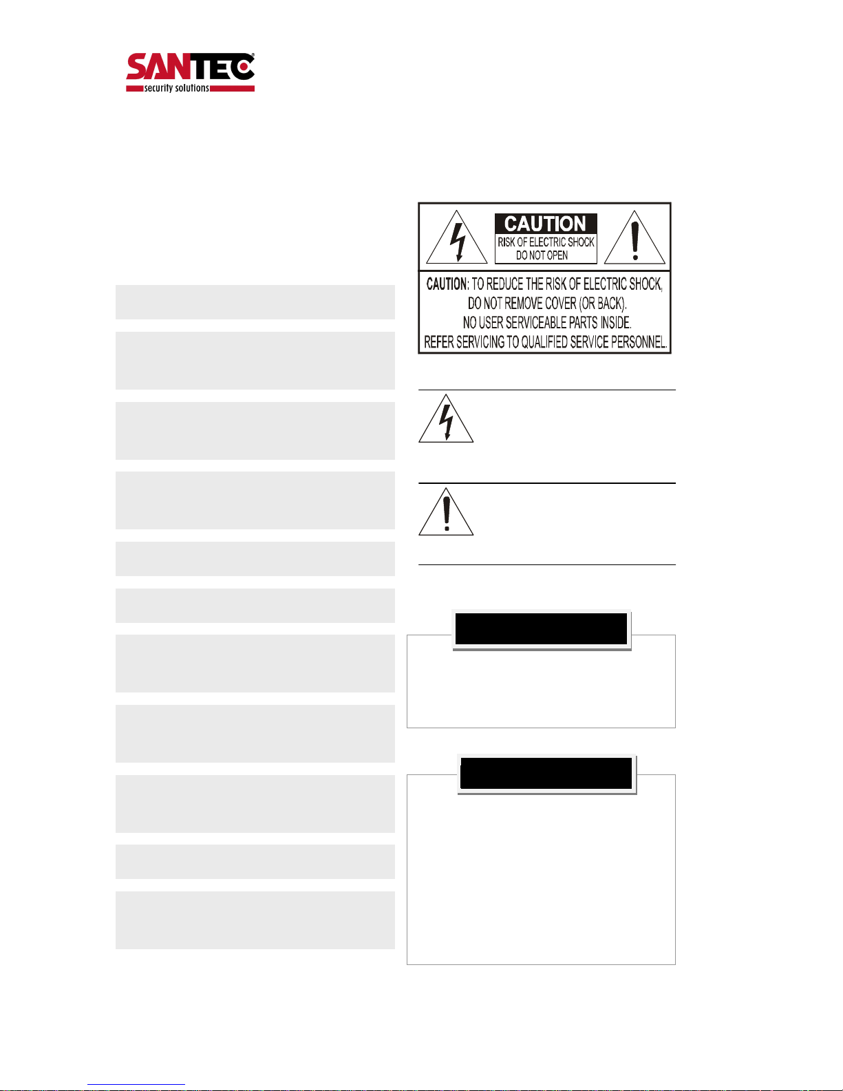
WARNING & CAUTION
If you fail to read this information and
handle the product incorrectly, death or
serious injury may occur.
1. Camera
2. Screws ( Ø4x16 screw 5EA )
3. Terminal block (5pin 2EA)
4. Manual
5. Screw Cap (2 EA)
The unit should be installed by the trained
Always stop using when the product emits
smoke or abnormal heat.
Never install the product in area exposed to
water, oil or gas.
Never install the product on a ceiling that
cannot hold its weight.
Never touch the power cord with wet hands.
Clean only with dry cloth.
Never install the product in extreme high or
low temperature.
Never drop hit strongly nor vibrate the
product.
Never expose the product to direct sunlight
or severe ray.
Never touch the front glass of the product.
Never install the product in areas exposed to
rain or water
This symbol is intended to alert the user to
the presence of un-
insulated “dangerous
voltage” within the product’s enclosure that
may be of sufficient magnitude to
constitute a risk of electric shock
to
persons.
This symbol is intended to alert the user to
the presence of
important operating and
maintenance (servicin
g) instructions in the
literature accompanying the appliance.
Never move Pan/Tilt by hands. It may
causes serious damage to the camera.
Warning
What’s in the box?

User manual / VDC-610ID
_________________________________________________________________________________
- Seite 5 -
GENETAL FEATURES
100X Zoom Mini Speed Dome
10X Optical Zoom with 10X digital zoom
±0.02° dome system accuracy with 1/4
micro step
With 0.1° technical accuracy, camera provides excellent
sensitive and delicate controlling on preset mode by
adapting 1/4 micro step and twin gear system
360° Endless Rotation
10X mini speed dome is capable of endless rotation of 360
degrees
Compensation function: preset position
The function minimizes the appearance of shaky images
caused by low-frequency vibration, wind and any impact
and maintains a normal horizontal resolution and sets the
starting point of pan/tilt on preset mode by using joystick
turning one time without turn off the power of the camera.
It is useful for outdoor surveillance and traffic monitoring
applications.
Over 200°/Sec Preset Speed
The 360° full pan function moves through a maximum of
200°/sec., enabling you to quickly pinpoint the spot you
want to watch. Tilt speed provides through a maximum
200°/sec on preset.
Polarity Protection of Power (DC12V)
This protection function prevents the power board from
being out and trouble when power source falsely connects
to the power terminals.
Filter changeable True Day/Night
Surveillance with optimum picture is possible owing to filter
changeable Day/Night (ICR block filter) function and DSS.
Auto IR cut filter removable function is auto controlling the
operation such as color picture plus infrared cut filter during
the day and black and white picture plus filter elimination at
night.
Indoor / Outdoor applications
Compact and minimize dome size provides various install
application to big shop, shopping center, airport, highway
and so on.
Quick Operation Keys
This camera provides quick functional keys in other to be
easily controlled by any other controller or DVR.
Various Surveillance Functions
Auto Scan repeats pan and tilt between two preset
positions with different speed and dwell time.
8 Group Tour up to 8 Programmable Group tours
available and each group is consisting up to 60 presets
step with different speed and dwell time with 16
characters.
164 Preset positions up to 164 programmable
preset positions are available with 16 characters
8 Patterns up to 8 programmable user-defined patters
are available with 16 characters and each one is
consisting 50 seconds, total 400 seconds.
8 Sectors up to 8 programmable user-defined sectors
are available with 16 characters
4 Privacy Masking Zones up to 4 programmable
user-defined privacy masking zones are available with
16 characters
4 Alarm input up to 4 alarms activate with preset,
tours, patterns.
200°/S – Manual speed
This camera provides up to 200°/sec of manual speed
and it’s adjustable from 10°/sec to 200°/sec by each
10°/sec
1/4” Sony Super HAD CCD
Equipped with Sony Super HAD CCD technology, these
particular camera provide excellent sensitivity and low
smear levels.
Intelligent Pan/Tilt Controlling
Intelligent Pan/Tilt function is continually decreases pan
and tilt speeds in proportion to zoom.
Aluminum case and PC cover
Elegance designed aluminum body and Poly
Carbonated dome cover prevent weather proofed install
environment (IP66 Rated)
.
Password Protection
User manual / VDC-610ID
_________________________________________________________________________________
- Seite 6 -
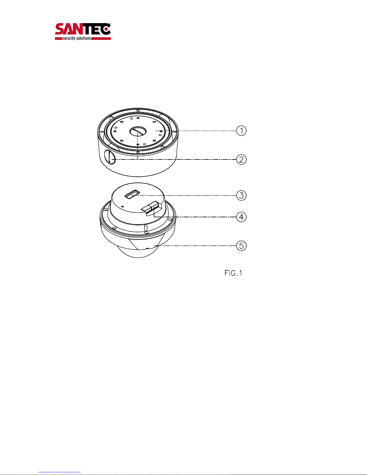
NAMES OF EACH PART
1. Surface Mount Adaptor
2. Cap Screw ( PT3/4 , 2EA )
3. Dip Switch
4. Terminal Block
5. Main body
User manual / VDC-610ID
_________________________________________________________________________________
- Seite 7 -
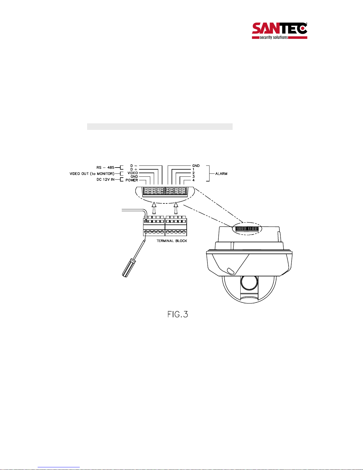
A. CONNECTION METHODS
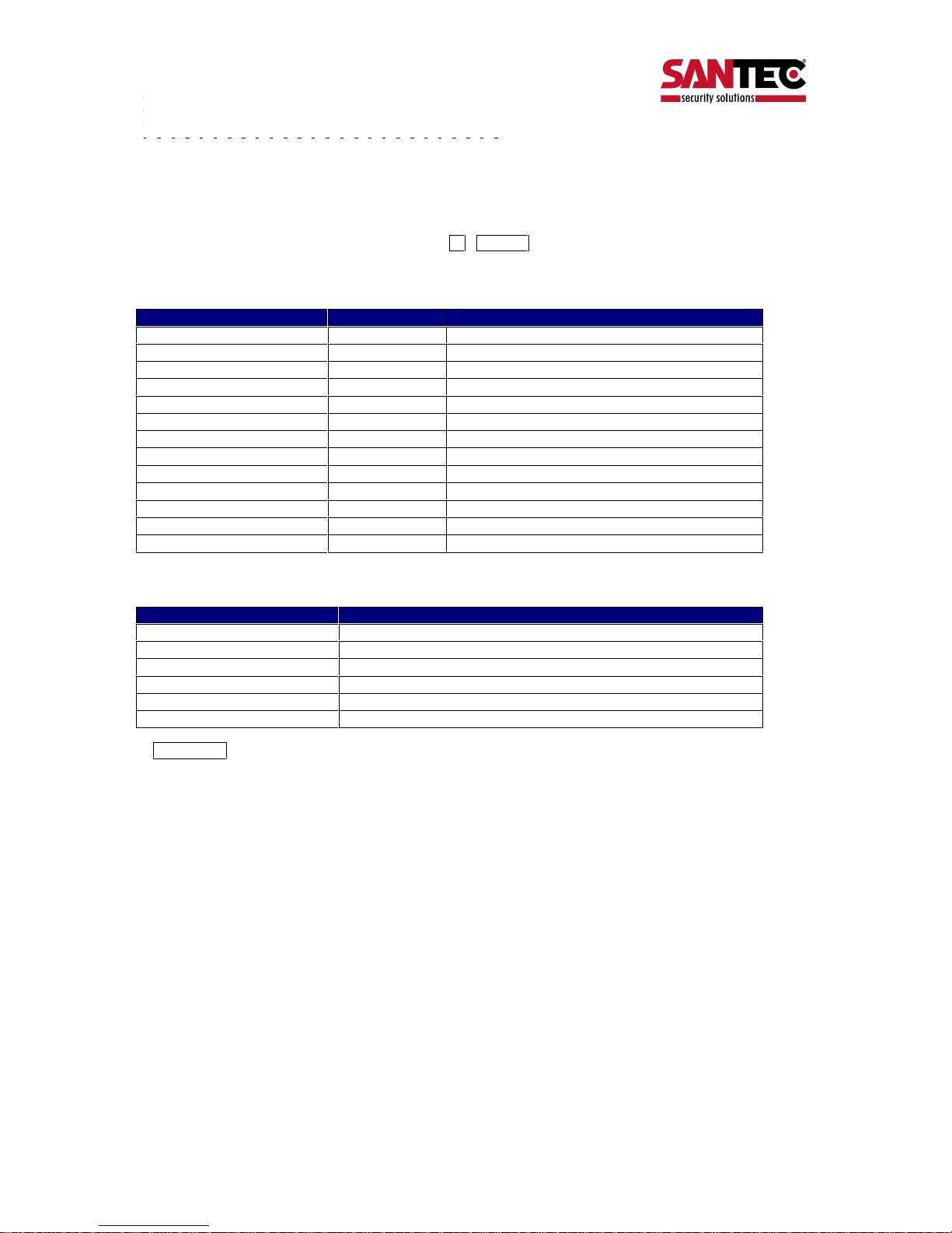
1. Loose the screws on the domes cover and remove it from the base.
(Screws won’t be removed)
2. Loose the screws which connect mount cover and Main base and separate dome cover from the main
base. (Screws won’t be removed)
3. Connect power (DC12V 1.5 A ) to Power and GND.
4. Connect video to Video and GND.
5. Connect communication cable to RS-485 connectors.
6. Connect alarm cable to GND like 1 and GND, 2 and GND, 3 and GND, 4 and GND.
(You can use both N.O / N.C methods. )
Don’t screw too tightly. It can be the cause of defect.
INSTALLATION
User manual / VDC-610ID
_________________________________________________________________________________
- Seite 8 -
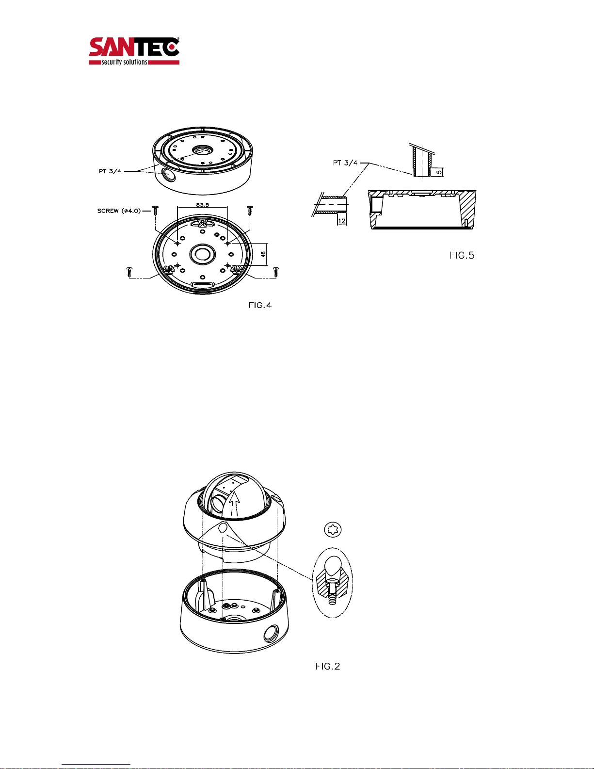
B. MOUNT
1. Fix the surface mount adaptor with 4pcs of screws on the place where you want to install.
(FIG.4)
2. When you use pipe, please note the standard size of pipe. (FIG.5)
3. You can re-assemble the domes.
User manual / VDC-610ID
_________________________________________________________________________________
- Seite 9 -
As the merit of this product, it has lots of function keys to support the following functions.
1-64 + preset and 101~200 + preset are used for preset and 65-100 + preset used for functions.
For example, to enter OSD MENU, press the button 95 +PRESET.
<Quick Operation Key Table 1, Pelco - D, P>
Number
Note Fu
nction
1 ~ 64, 100~200 +Preset PRESET Executing Preset 1 ~ 64
65 + Preset PRESET STATUS Display Preset Status
66 +Preset AUTO SCAN Executing Auto Scan
67 +Preset AUTO FLIP Selectable On/Off/Auto in Auto Flip function
71~78 +Preset GROUP TOUR Executing Group Tour #1 ~ #8
81~88 +Preset PATTERN Executing Pattern #1 ~ #8
91 + Preset ZERO POSITION
92 + Preset FREEZE
93 + Preset BLC MODE Selectable On/Off in BLC function
94 + Preset D/N MODE Selectable Day/Night Mode (Auto/Day/Night Mode)
95 + Preset OSD MAIN MENU To enter OSD Main Menu
96 + Preset FOCUS ADJUST Focus adjusting
97 +Preset ALARM Selectable Enable/Disable all Alarms
<Quick Operation Keys Table 2> Use these function keys if controller has these keys>
* 65 + preset : Status Report , If user presses any key, it disappears.
Menu
Function
Tilt Up / Down Sub menu cursor moves up / down
Pan Left / Right Enter to the sub menu or status change or decrement
Focus Near Using for Enter key when user select YES or NO
Focus Far Using for function changing keys when set coordinate
Zoom Tele Status cursor to the right
Zoom Wide Status cursor to the left
QUICK OPERATING KEYS

User manual / VDC-610ID
_________________________________________________________________________________
- Seite 10 -
When Power on, DIAGONOSTIC is operated.
The following messages are displayed on the monitor.
A. Pan Origin Test
Zero point of Pan is founded after Panning test.
B. Tilt Origin Test
Zero point of Tilt is founded after Tilting test.
C. TX connection Test
Countdown from 60 seconds for TX Connection Test,
during 60 seconds, the camera must receive a signal from any keys of controller or DVR s.
When received the correct signal, OK is displayed after TX CONNECTION TEST.
* If “No Tested” is displayed on the monitor,
- Camera did not receive the any signal.
- Camera did receive the signal but not correct it.
- User should check protocol, baud rate and RS-485 connection.
D. Camera Comm. Test
Communication test with the camera is automatically checked.
OK should be displayed in these four tests before installation.
If all the above Tests are OK, “NOW EEPROM CHECKING” and “EEPROM OK” is displayed and the camera is
DIAGNOSTIC
CAMERA ID : 001
BAUD RATE : 2400 BPS
WAITING………
PAN ORIGIN CHECK OK
TILT ORIGIN CHECK OK
TX CONNECTION TEST OK
CAMERA COMM TEST OK
 Loading...