

Santec VDC-295IDH User Manual
Version 1.0sfi/1214/engl/A5
USER MANUAL
High speed dome camera
Model:
VDC-295IDH

Dear customer,
Thank you for purchasing a high quality SANTEC device.
We recommend that you read this manual thoroughly before operating your new system for
the first time. Please follow all instructions and observe the warnings contained in this
manual.
Please contact your local dealer or use the SANTEC Service Hotline if you have any
questions or if you wish to claim for a service or warranty.
You will find further information on our website:
www.santec-video.com
All rights reserved. This publication may not be reproduced, stored in a retrieval system or
transmitted, in any form or by any means (electronic, mechanical, photocopying, recording or
otherwise), without the written prior permission of SANTEC BW AG.
No reproduction of any part or excerpts thereof are permitted.
Errors excepted. Specifications are subject to change without notice for quality improvement.
SANTEC is a registered trademark of SANTEC BW AG. All other companies or products
mentioned in this publication are trademarks, registered trademarks or brands of the
respective company.
© Copyright by: SANTEC BW AG
An der Strusbek 31
22926 Ahrensburg
Germany
www.santec-video.com

User manual
VDC-295IDH
_________________________________________________________________________________
- 3 -
Table of contents
Safety precautions 4
Safety instructions 5
1. Introduction 7
1.1 Features 7
1.2 Typical system configuration 8
1.3 Assembly of bubble ring 9
2. Installation and configuration 10
2.1 Items included in the delivery 10
2.2 Basic configuration 11
2.3 Setting the dome camera termination 12
2.4 Fail-safe network 13
2.5 Setting the dome camera address (IP) 14
2.6 Setting the dome camera protocol 15
2.7 Connections 16
2.8 Operation 17
3. Program and control 18
3.1 Dome camera selection 18
3.2 Accessing the OSD menu 18
3.3 OSD control 19
3.4 Auto-Scan 20
3.5 Presets 24
3.6 Shortcuts for presets 26
3.7 Tour 27
3.8 Pattern 29
3.9 Alarm 30
3.10 Area title 32
3.11 Privacy zone 33
3.12 Camera setup 34
3.13 Dome setup 38
3.14 Function run 47
3.15 Motion detection 48
4. Technical specifications 49
5. Dimensions 50
User manual
VDC-295IDH
_________________________________________________________________________________
- 4 -
General
Please read this user manual carefully before starting to operate this device. Please retain
this user manual for future reference.
Safety precautions
Overcharge
Never expose the power socket or the power cord to electrical overcharge. This may lead to
fire and life-threatening shocks.
Thunderstorms
If there is a thunderstorm or if the device has not been in use for a longer period of time,
please always disconnect the device from the power source. Disconnect the power cord.
This protects the device from lightning damages or overcharging.
Entry of liquids or items
Never poke with metalic items in the ventilation slots of the device. You may touch
dangerous live power items which may lead to an electronic shock, a short circuit or fire.
CE compliance
This appliance complies with the CE guidelines.
Attention:
Any changes or modifications to this appliance which have not been explicitly approved of by
the respective regulatory authority, may lead to a prohibition of usage of this appliance.

User manual
VDC-295IDH
_________________________________________________________________________________
- 5 -
Safety instructions
Before operating the appliance, please read this manual carefully and retain it for further
reference.
Before cleaning the appliance, it has to be switched off and unplugged from the power outlet.
Wipe the appliance with a soft damp cloth.
Do not use harsh cleansers or aerosols for cleaning. The type label may not be replaced.
Do not use attachments unless recommended by the manufacturer as they may affect the
functionality of the appliance and result in the risk of fire, electric shock or injury.
Never install the appliance in areas exposed to water or other liquids.
The appliance has to be installed in a safe and stable location which is able to carry the weight of
the appliance. Quick stops, excessive force, and uneven surfaces may cause the appliance to fall
causing serious injury to persons and damage to objects.
Openings in the appliance, if any, are provided for ventilation to ensure reliable operation of the
appliance and to protect if from overheating. These openings must not be covered or blocked.
Please make sure that the appliance does not overheat.
The appliance should only be operated from the type of power source indicated on the marking
label. If you are not sure of the type of power supplied at the installation location, please contact
your local dealer.
An appliance which is powered through a polarized plug (a plug with one blade wider than the
other) will fit into the power outlet only one way. This is a safety feature. If you are unable to insert
the plug into the outlet, try reversing the plug. Do not defeat the safety purpose of the polarized
plug.
If the appliance is powered through a grounding-type plug, the plug will only fit into a grounding-
type power outlet. This is a safety feature. If your outlet does not have the grounding plug
receptacle, contact your local electrician.
Route power cords and cables in a manner to protect them from damage by being walked on or
pinched by items places upon or against them.
For protection of the appliance during a lightning storm or when it is left unattended and unused
for a longer period, unplug the appliance from the wall outlet. Disconnect any antennas or cable
systems that may be connected to the appliance. This will prevent damage to the appliance due to
lightning or power-line surges.
Do not overload wall outlets and extension cords as this can result in a risk of fire or electric
shock.
Never insert items into the openings of the appliance. They may touch parts under electric current
which may cause an electric shock.
Never pour any liquids over the appliance.
User manual
VDC-295IDH
_________________________________________________________________________________
- 6 -
In case of any operating interruption or a complete operating failure please switch off the
appliance and disconnect it from the wall outlet. Never attempt to service or repair the appliance
yourself, as opening or removing covers may expose you to dangerous voltage or other hazards.
Refer all servicing to qualified service personnel.
When replacement parts are required, be sure that the service technician uses replacements parts
specified by the manufacturer or that have the same characteristics as the original part.
Unauthorized substitutions may result in fire, electric shock or other hazards.
Upon completion of any service or repairs to the appliance, ask the service technician to perform
safety checks to verify that the appliance is in proper operating condition.
The appliance should only be installed by qualified service personnel and has to comply with local
specifications and regulations.
Never point the camera at an object with a high degree of luminance. Bright vertical or horizontal
lines can result in a distortion (outshine) of the entire image on the monitor. This artifact is not an
error but a particularity of semiconductor CCDs when they are directly exposed to a powerful light
source.
At the installation site, the camera has to be adjusted to the given light conditions (see OSD).
Please respect the local legal regulations on waste if you need to dispose of discarded appliances.
This symbol means that electrical appliances need to be disposed of properly and not
simply with unsorted household refuse. Please respect local regulations on waste
disposal.
About this user manual
This manual aims at assisting the user on how to operate camera VDC-295IDH.
This manual is subject to rigid quality control. However, no guarantee can be given that
mistakes are not present. We reserve the right to make changes to the manual without prior
notice.
Before operating the appliance, please read this manual carefully and retain it for further
reference.
Verify that all appliance items are included in the delivery. Should items be missing, do not
operate the appliance and contact your local dealer.
Never attempt to repair the appliance yourself. This should only be done by qualified service
personnel.
Improper handling of the appliance will invalidate the warranty.

User manual
VDC-295IDH
_________________________________________________________________________________
- 7 -
1. Introduction
1.1 Features
The dome camera and the keyboard are the building blocks for any video surveillance
system. Using multiple keyboards and multiple dome cameras, no place is too large for
monitoring.
Fast, compact day/night camera with integrated 22x to 36x optical motor zoom lens
(depending on the camera model) and an additional 12x digital zoom
240 preset positions
8 Tours consisting of preset, pattern, auto-scan and other tours can be programmed
with over 300 functions and preset location. While moving, each preset scan can be
watched in smooth vector scan mode.
16 auto-scans including vector scan and 360° endless panning with 13 speed steps
8 patterns (up to 500 seconds)
8 privacy zones
16 area titles
8 alarm inputs / 4 additional outputs (NC & NO)
Variable speed of 0.1°/s up to 380°/s;
3 variable speeds (slow, normal, turbo);
turbo-speed of max. 380°/s with Ctrl-key pressed
Pan/tilt speed is inversely proportional to the zoom ratio
Max. speed is 380°/s with preset command
Auto calibration from 0.1° to 6° (tilt range is 0° to 180°).
Programmable user preferences (alarm, preset, title, etc.)
180° digital flip or 90° auto flip function (depending on model)
Up to 999 selectable camera addresses
Multi-language OSD menu, password confirmation
Function run menu using recorders without function keys (pattern, scan, etc)
Built-in RS-485/422 receiver driver
Additional clear bubble with black liner (shelter) for concealing the camera for extra
camera protection (included in the delivery)
Optionally available: Tinted bubble
User manual
VDC-295IDH
_________________________________________________________________________________
- 8 -
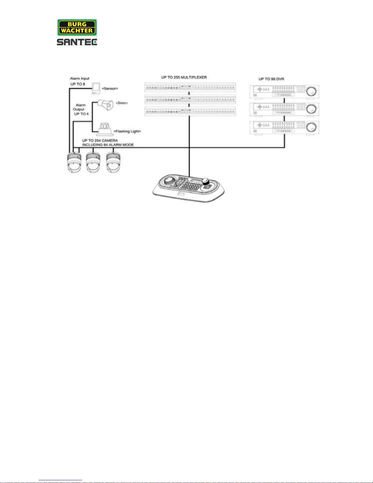
1.2 Typical system configuration
Fig. 1: Typical system configuration
User manual
VDC-295IDH
_________________________________________________________________________________
- 9 -
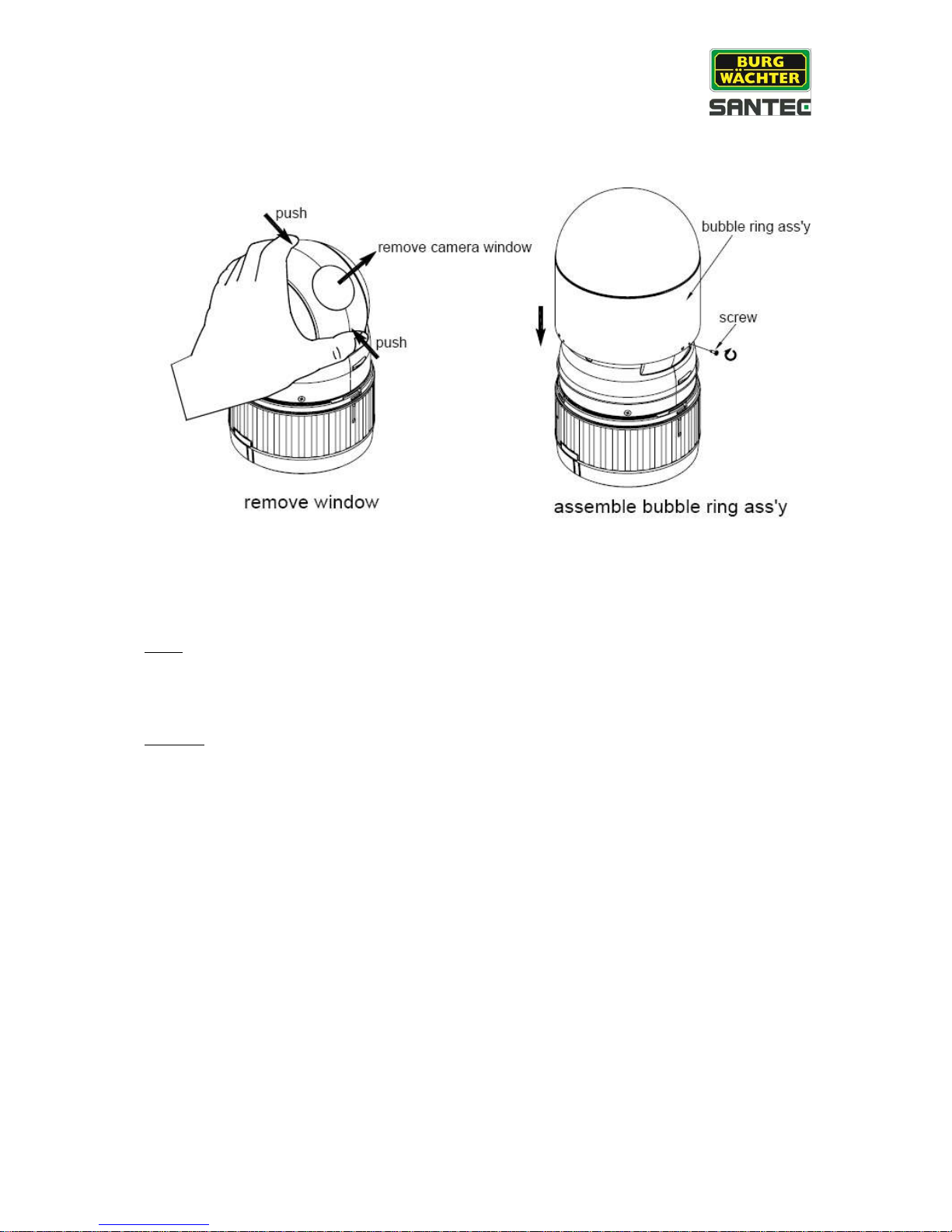
1.3 Assembly of bubble ring
Fig. 2: Assembly of bubble ring
Note:
It is recommended to remove camera window for improving the picture quality when you use
the bubble ring.
Caution:
When installing the speed dome on a high pole outside, caution should be taken to avoid
vibration and shaking of the dome caused by e.g. wind or shock or passing heavy vehicles.
If the pole is not stable enough, it may cause malfunction when in tilt position.
User manual
VDC-295IDH
_________________________________________________________________________________
- 10 -
2. Installation and configuration
2.1 Items included in the delivery
1x dome camera VDC-295IDH
1x clear bubble ring
1x 10-pin connector
2x 12-pin connector
1x user manual
Caution:
Be sure to have caution labels (E version only) on both the body and the base of the camera.
Different versions will not support inputs and outputs.
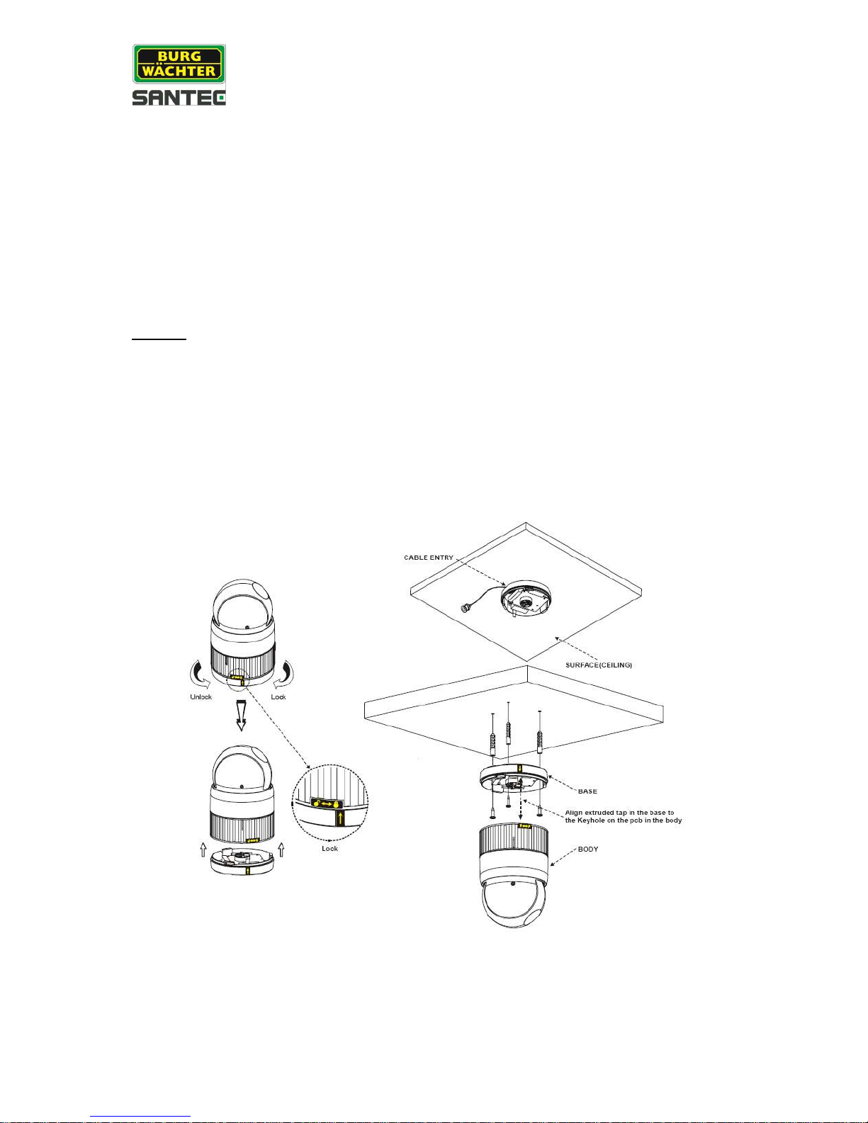
The dome camera is designed for use in surface mounting applications and the mounting
surface should be capable of supporting loads up to 4.5 kg.
The dome camera’s base should be attached to a structural object, such as hard wood, a
wall stud or ceiling rafter that supports the weight of the dome camera.
Fig. 3: Installation
User manual
VDC-295IDH
_________________________________________________________________________________
- 11 -
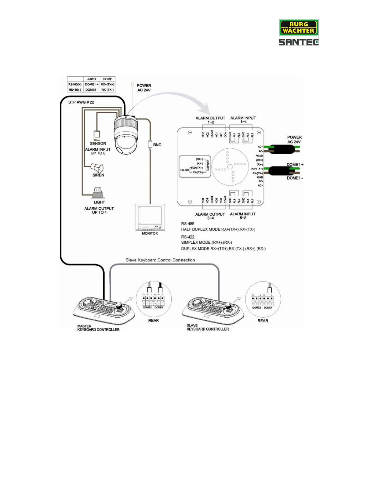
2.2 Basic configuration
Fig. 4: Basic configuration
User manual
VDC-295IDH
_________________________________________________________________________________
- 12 -
The dome camera must be installed by qualified service personnel in accordance with all
local and federal electrical and building codes. The system should be installed according to
figures 4 through 9.
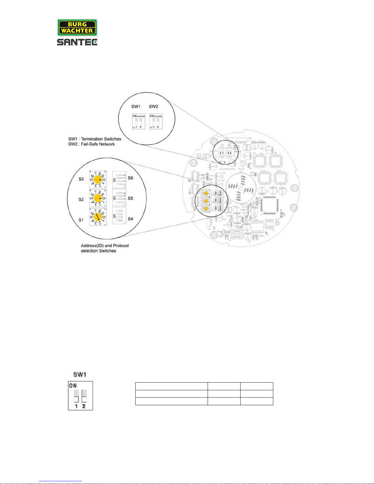
Fig. 5: Layout of switches
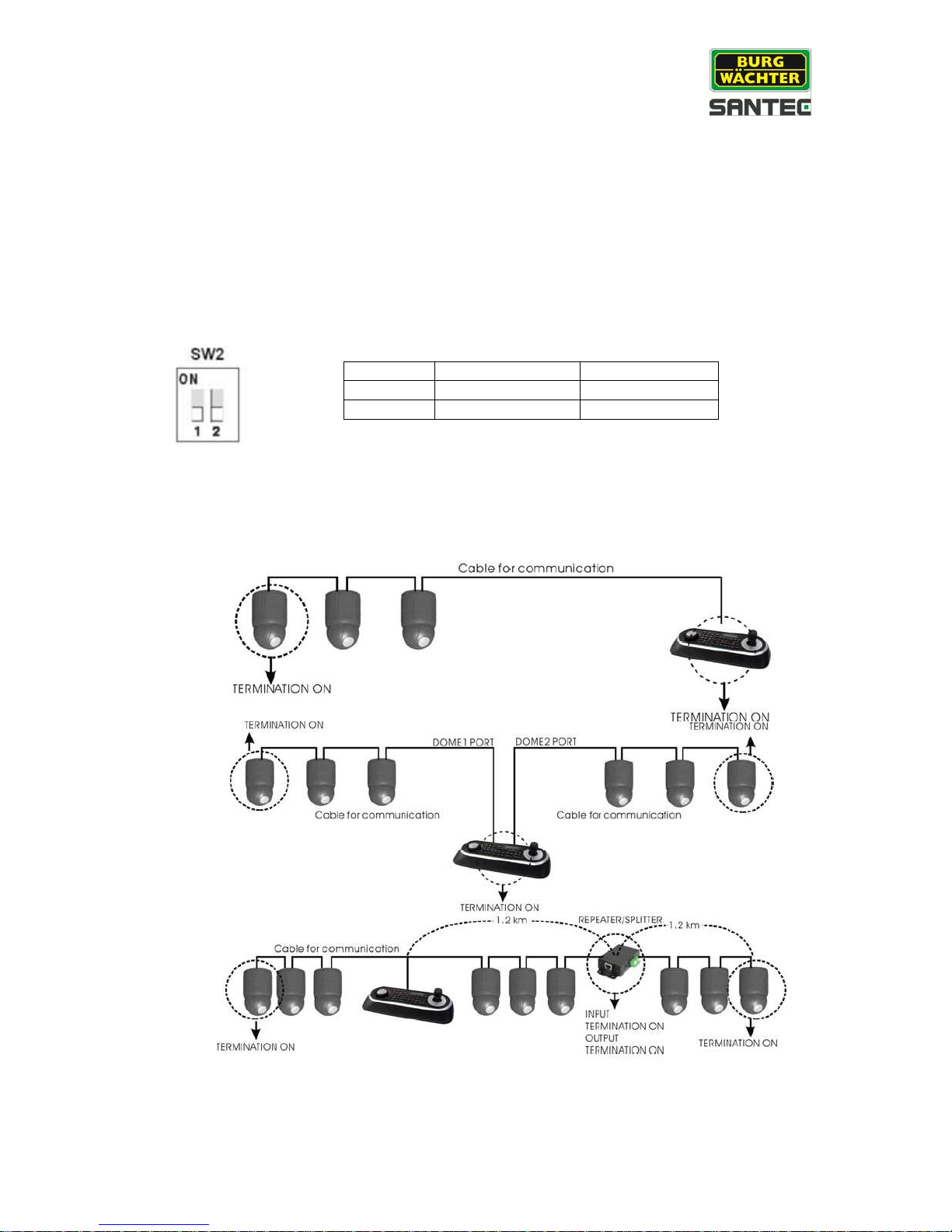
2.3 Setting the dome camera termination
The device which is connected at end of line, whether it is a dome camera or a keyboard,
must be connected by a terminated cable. The termination of the cable is achieved by the
appropriate DIP switch setting. Without proper termination, control signal errors may occur.
The total length of the communication cable should not exceed 1.2 km.
Fig. 6: Setting the dome camera termination
SW1
1
2
Terminated
ON
ON
Not terminated
OFF
OFF
User manual
VDC-295IDH
_________________________________________________________________________________
- 13 -
2.4 Fail-safe network
When you control the dome by a device other than your own keyboard, errors may occur
in the serial communication. The reason for this is caused by the other device without the
fail-safe network.
In this case, you solve the problem by setting the DIP switch to “ON” of the dome camera
nearest to the other device.
Fig. 7: Setting the dome camera termination
Fig. 8: Termination diagram (example)
SW2 1 2
ON
Pull up
Pull down
OFF
None
None

User manual
VDC-295IDH
_________________________________________________________________________________
- 14 -
2.5 Setting the dome camera address (ID)
To prevent damage, each dome camera must have a unique address (ID). When installing
multiple dome cameras using a multiplexer, it is suggested that the dome camera address
matches the multiplexer’s port number.
If you want to set the camera ID to more than 999, please contact your service provider.
Example:
Port 1 = dome 1, port 2 = dome 2 … port 16 = dome 16.
If more than 16 dome cameras are installed using two or more multiplexers, the ID of the
dome camera should be made up of the ID of MUX x no. of camera IN
(example: multiplexer ID= n, Camera IN= m; then dome ID =16x (n-1)+m )
Please refer to figures 4-5 for setting the dome camera address (ID) and protocol selection.
Fig. 9: Setting the dome camera address (ID)
Dome ID
S3
S2
S1
1 0 0
1
2 0 0
2
… … …
…
999 9 9
9
User manual
VDC-295IDH
_________________________________________________________________________________
- 15 -
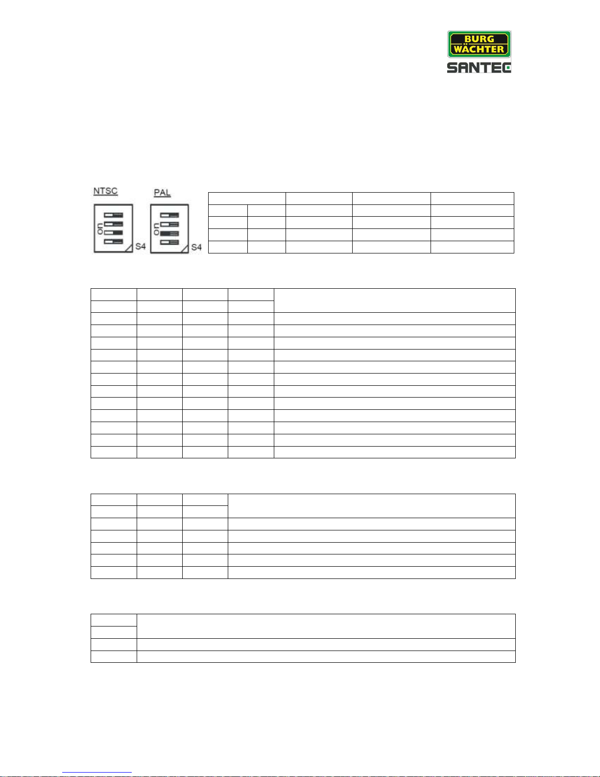
2.6 Setting the dome camera protocol
If a dome camera is to be installed with a SANTEC keyboard, select the SANTEC protocol.
Please consult the service personnel if a dome camera is installed with a device other than a
keyboard.
D5
D6
D7
D12
Protocoll
S5-1
S5-2
S5-3
S6-4
Off
Off
Off
Off
F2, F2E, PELCO-D, PELCO-P, default: SANTEC
Off
Off
On
Off
F2, F2E
Off
On
Off
Off
Sensormatic RS-422
Off
On
On
Off
PELCO-D, PELCO-P
On
Off
Off
Off
Vicon
On
Off
On
Off
Ernitec
On
On
Off
Off
Reserved
On
On
On
Off
F2
Off
Off
Off
On
Philips (Bosch)
Off
Off
On
On
Reserved
Off
On
Off
On
Dynacolor
Off
On
On
On
Reserved
D8
D9
D10
Baudrate
S5-4
S6-1
S6-2
Off
Off
Off
2400 bps
Off
Off
On
4800 bps
Off
On
Off
9600 bps (default)
Off
On
On
19200 bps
On
Off
Off
38400 bps
D11
Parity bit
S6-3
On
None
Off
Even
Fig. 10: Protocol selection switches
Switch
ON
Off
Function
D1
S4-1
Enable
Disable
Alarm
D2
S4-2
PAL
NTSC
NTSC/PAL
D3
S4-3
Reserved
D4
S4-4
RS-422
RS-485
RS-422/RS-485

User manual
VDC-295IDH
_________________________________________________________________________________
- 16 -
2.7 Connections
RS-485/-422 connection
The dome camera can be controlled remotely by an external device or control system, such
as a control keyboard, using RS-485 half-duplex, RS-422 duplex or a serial simplex
communications signals. Connect Rx+ and Rx- with Tx+ and Tx- of the RS-485 control
system.
If the control system is RS-422, connect Rx+(Tx+), Rx+(Tx-) and Rx+, Rx- of the dome
camera to Rx+, Rx- and Tx+, Tx- of the control device respectively.
Monitor connection
Connect the video output (BNC) connector to the monitor or the video input.
Connecting alarms AL 1 to 8 (alarm input)
You can use external devices to make the dome camera react to events. Mechanical or
electrical switches can be wired to the AL (alarm input) and GND (ground) connectors.
See chapter 3 for programming and operating alarm inputs.
Note:
All connectors marked with GND have the same reference.
Connect the ground side of the alarm input and/or the alarm output to the GND connector.
NC (NO) 1 to 4 (normally close or normally open: alarm output)
The dome camera can activate external devices such as buzzers or lights. Connect the
device to the NC (NO) (alarm output) and COM (common) connectors.
See chapter 3 for programming and operating alarm inputs
Connecting the power
Connect the plug of the power supply unit (24 V AC, 850mA) to the dome camera.
Only use certified/listed class 2 power sources.
 Loading...