

Santec TH-5034 Installation Instructions Manual
INSTALLATION INSTRUCTIONS
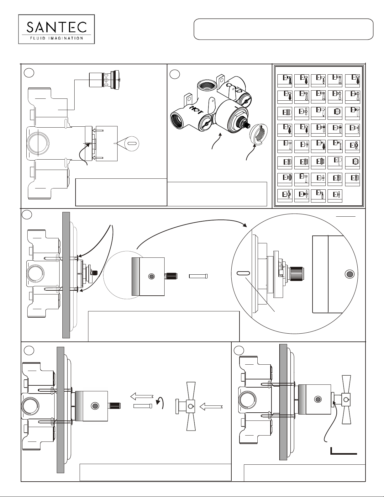
TH-5034 (3/4” THERMAX THERMOSTATIC VALVE AND TRIM)
1
E
V
E
E
E
Y
V
D
L
O
A
V
B
GROOVE ON THE
VE BODY
VAL
Align the projection on the
sleeve with projection on the top
lip of the body and then slide
it on the valve body.
3
Plate Mounting Screws
l
l
a
W
L
S
PROJECTION ON
THE SLEEVE
2
SLEEVE IS ON THE
VALVE BODY FULLY
When sleeve is fully on the valve body
temperature limiter will go to the stem
aligning the mark on the limiter to the mark
on the sleeve and body.
HAND LE TRIM
AA
00TH-AA * 00TH-AC *
CD
00TH-CD * 00TH-CN *
ER
00TH-ER * 00TH-FF *
LC
00TH-LC * 00TH-LL *
ML
00TH-ML * 00TH-MX *
RE
TEMPERATURE
LIMITER
00TH-RE * 00TH-RP *
TT
00TH-TT *
XL
00TH-XL *
10 5111 00055510011100000095999555
10 5111 00055510011100000095999555
10 5111 0005551 00111000 00095999555
10 5111 0005551 00111000 00095999555
10 5111 0005551 00111000 00095999555
10 5111 00055510011100000095999555
10 5111 0005551 0011100000095999555
10 5111 0005551 0011100000095999555
10 5111 0005551 00111000 00095999555
AC
CN
FF
10 5111 0005551 00111000 00095999555
LL
MX
RP
VL
00TH-VL *
XA
10 5111 0005551 001110000009 5999555
00TH-XA *
10 5111 0005551 00111000 00095999555
10 5111 0005551 00111000 00095999555
10 5111 0005551 00111000 00095999555
10 5111 00055510011100000095999555
10 5111 0005551 001110000009 5999555
10 5111 0005551 001110000009 5999555
BF
00TH-BF * 00TH-CA *
CV
00TH-CV * 00TH-DD *
HH
00TH-HH *
LM
00TH-LM * 00TH-LS *
NC
00TH-NC * 00TH-NL *
RX
00TH-RX * 00TH-SL *
VX
00TH-VX *
TD
00YY-TD
10 5111 0005551 00111000 00095999555
10 5111 000555100111000 00095999555
CA
10 5111 0005551 00111000 00095999555
10 5111 0005551 00111000 00095999555
DD
10 5111 0005551 00111000 00095999555
JC
SAME AS TL *
10 5111 0005551 00111000 00095999555
10 5111 0005551 00111000 00095999555
LS
10 5111 0005551 00111000 00095999555
NL
SL
10 5111 00055510011100000095999555 10 5111 00055510011100000095999555
WE
10 5111 0005551 00111000 00095999555
00TH-WE *
10511100055510011100000095999555
TX
00YY-TX
10 5111 0005551 00111000 00095999555
CC
00TH-CC *
10 5111 0005551 00111000 00095999555
DV
00TH-DV *
10 5111 0005551 00111000 00095999555
LA
10511100055510011100000095999555
PH-1111-1 *
10 5111 0005551 00111000 00095999555
LV
00TH-LV *
10 5111 0005551 00111000 00095999555
NX
10 5111 0005551 00111000 00095999555
00TH-NX *
10 5111 00055510011100000095999555
TL
10511100055510011100000095999555
00TH-NX *
WG
10 5111 00055510011100000095999555
10 5111 00055510011100000095999555
00TH-WG *
10511100055510011100000095999555
Top View
110111111000
10011100000090999000
Numerical Dial
Mounting Screw
Temperature Dial
l
l
a
W
Put on the plate aligned to the wall and screw in
the plate mounting screws.
Put on the thermostatic dial on the valve stem.
Match 100 mark with the center mark on the sleeve
to adjust the temperature at lowest level.
4 5
l
l
a
W
110111111000
10011100000090999000
Numerical Dial
Mounting Screw
Temperature Dial
l
l
a
W
INSERT THE NUMERICAL DIAL MOUNTING SCREW THROUGH THE
COAXIAL HOLE IN THE TEMPERATURE DIAL STEM.
110111111000
10011100000090999000
CENTER MARK
l
l
a
W
110111111000
10011100000090999000
l
l
a
W
PUT ON THE HANDLE ON THE STEM AND SCREW
IN THE SET SCREW BY THE PROVIDED ALLEN KEY.
Set Screw
Allen key
Page 1
INSTALLATION INSTRUCTIONS
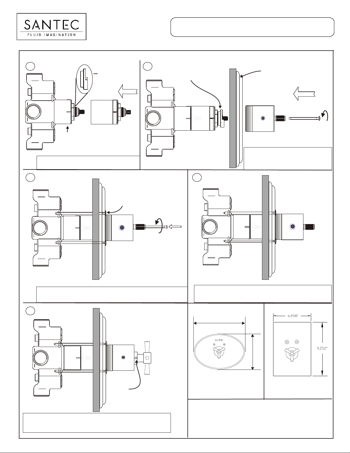
TH-5034 (3/4” THERMAX THERMOSTATIC VALVE AND TRIM WITH OPTIONAL EXTENSION)
1 2
Take temperature
limiter out
Sleeve
Thermostatic
Put back temperature limiter
through the extension stem
Extension
PUT ON THE THERMOSTATIC EXTENSION ON THE
STEM OF THE VALVE. FULLY SLIDE IT IN.
3 4
l
l
a
W
Plate Mounting Screws
110111111000
10011100000090999 000
Thermostatic
l
l
a
W
Plate
110110
1001009090
Extension Screw
l
l
a
PUT ON THE THERMOSTATIC PLATE ON
W
THE WALL, AND PUT ON THE MOUNTING
SCREWS. AFTER THAT PUT ON THE
TEMPERATURE DIAL ON IT.
l
l
a
W
110111111000
10011100000090999 000
To drive in the extension screw
l
l
a
you need to have a thin width
W
screw driver which can go in the
blind hole of the dial gauge.
Insert long extension screw through the coaxial hole in the temperature
dial. A long thin screw driver would be needed to firmly tighten this screw.
This screw will hold the extension and the temperature dial.
5
l
l
a
W
110111111000
10011100000090999000
l
l
a
W
Put on the handle on the stem. Put on the set screw on the
base of the handle. Firmly tighten the set screw.
Assembly looks like this.
Set Screw
l
l
a
W
After putting on long extension screw, temperature dial and plate
with mounting screws assembly looks like this.
9.75”
6.75”
XXXX
RMA
RRRMMMAAA
THE
TTTHHHEEE
SANTEC
THERMOSTATIC PLATE
Santec Inc.
3501 Challenger Street, Torrance, CA 90503
Tel: (310) 542-0063 Fax (310) 542-5681
Www.santecfaucet.com
THERMOSTATIC PLATE
SANTEC
Page 2
 Loading...