

Santec ESTATE, PB-3750 Series Manual
MODEL NUMBER
PB-3750
ESTATE SERIES
PRESSURE BALANCED TUB/SHOWER VALVE
DESCRIPTION
This product is precision engineered to provide satisfactory performance provided it is installed and operated in accordance with our
recommendations contained in this manual. In order to fully enjoy the comfort, safety and the reliability of your pressure balancing valve,
be certain to familiarize yourself with the contents of this manual.
WALL LINE
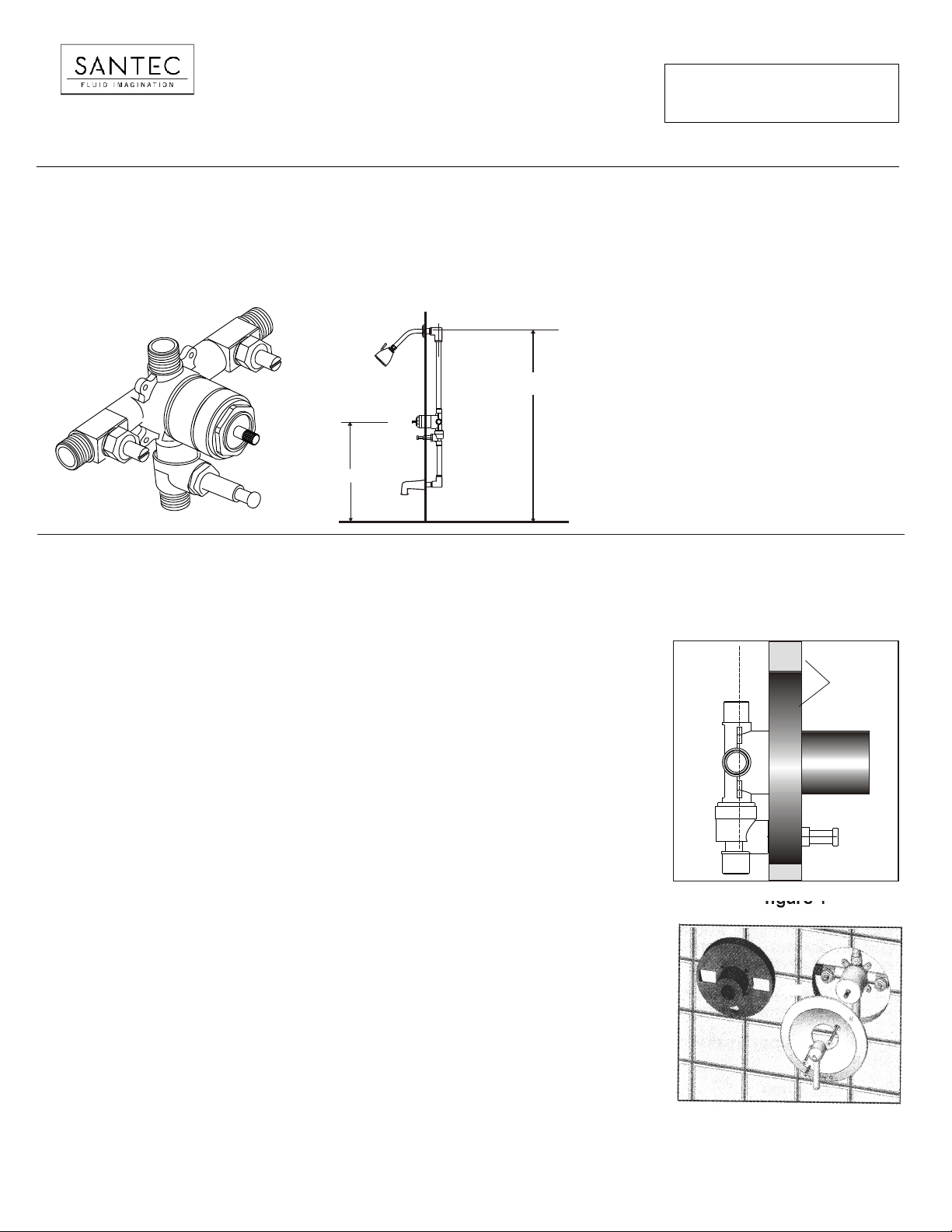
SPECIFICATIONS AND DIMENSIONS
78”
Minimum operating pressure 20 psi
Maximum operating pressure 145 psi
Maximum test pressure 500 psi
Hot and cold water inlets ½" IPS
33"
FLOOR
LINE
Shower outlet ½" IPS
Flow capacity 5 USGPM@ 50 psi
Finished wall adjustment : see Illustration
INSTALLATION
NOTE: Failure to follow these instructions may cause damage or improper operations and nullify the warranty.
ROUGH IN AND VALVE
- Make sure the water supplies are off
.
1. Rough valve body into wall, connecting piping to ½" female copper
Important: note "up" and "down" markings on back of valve.
2. The depth of rough-in should account for thickness of wall materials to be used
(combined thickness of wall board and finished wall material) .
Face of guard should be flushed with finished wall surface (see figure 1).
FLUSH
3. Anchor installation to bracing between studs (ears on the valve body can be used for
this by removing the plastic guard) - otherwise, anchor the connection piping.
4. Valve should be pressurized and tested for leaks at the connections. S
firmly against the stud. Make sure the ½" shower outlet is in the up position.
5. Plastic guard should be left attached to the valve until finished the wall material is installed.
6. After wall is finished, remove plastic guard and replace with trim sleeve and
escutcheon plate (figure 2).
Orient handle so that lever is pointed to off as marked on plate.
.
ecure the valve
KEEP THIS INSTRUCTION BOOKLET FOR FUTURE REFERENCE
finished wall
figure 1
figure 2
PAGE 01
INSTALLATION INSTRUCTIONS
PB-3750
IMPORTANT!!!! SETTING HOT LIMIT STOP
The removal of the warning label barrier on the face of this mixing valve constitutes the transfer of liability from the manufacturer to
the installer under the laws of the United States. It is the installer's responsibility to set the maximum output temperature of the valve to
no more than 120°f, in accordance with ASSE/ANSI standard 1016 -1996 dealing with individual thermostatic, pressure balancing and
combination pressure balancing and thermostatic control valves for individual fixtures section 4.2,2., temperature limit setting.
TO PROPERLY SET THE LIMIT RING, YOU MUST USE A THERMOMETER OR CALIBRATED SENSING DEVICE TO ACCURATELY
MEASURE THE OUTLET WATER TEMPERATURE. THE ADJUSTMENT RING IS POSITIONED AS FOLLOWS:
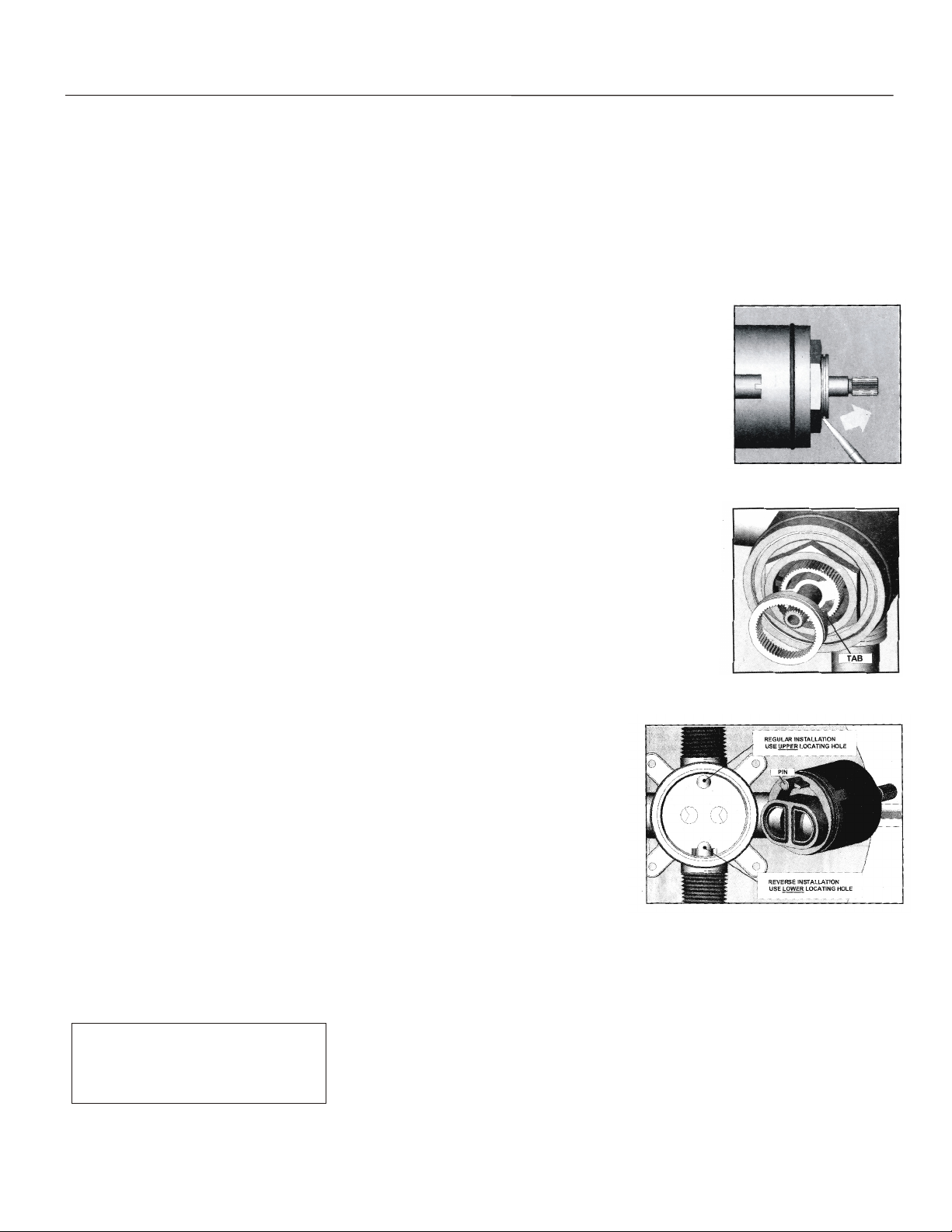
1. Expose the top of the cartridge by removing the trim sleeve from the valve body.
Do not remove the hex nut holding it in place. (See Figure 3)
2. Remove the grey adjustment ring by placing the blade of a knife into the
groove and prying it off (see figure 3).
3. Note the stop tab on the bottom of the ring (see figure 4). The further it is reoriented in a counter clockwise direction, the shorter the travel allowed (and thus, the lower the temperature output possible).
Important: before re-orienting the ring, be sure the stem is in the full off position.
REVERSING CARTRIDGE FOR BACK-TO-BACK INSTALLATIONS ONLY
When a valve is installed with reversed supply connections (typically in a back-to-back situation),
the cartridge can be reversed to allow normal operation (see figure 5).
1. Remove trim sleeve to expose top of valve.
2. Loosen and remove hex nut above cartridge.
3. Remove cartridge from valve cavity.. Look into cavity to see upper and lower locating
holes for cartridge pin.
4. Re-insert cartridge, aligning the pin with lower locating hole (partially cut away by
discharge opening). Press cartridge in firmly to assure that pin is properly inserted.
5. Secure cartridge by tightly reassembling The hex nut. Reassemble trim.
EPLACING CARTRIDGE
SAME BASIC PROCEDURE AS ABOVE (REVERSE IF NECESSARY).
figure 3
figure 4
figure 5
Santec Inc.
3501 Challenger Street, Torrance, CA 90503
Tel: (310) 542-0063 Fax (310) 542-5681
www.santecfaucet.com
PAGE 02
 Loading...