

Santec 9527KL-TM, 9529KL-TM, 9527KR-TM, 9529KR-TM, 9527KT-TM Installation Instruction
...
Please read the instructions completely before beginning the installation.
Rev 06/2016
Installation Instruction
KLASSICA COLLECTIONS
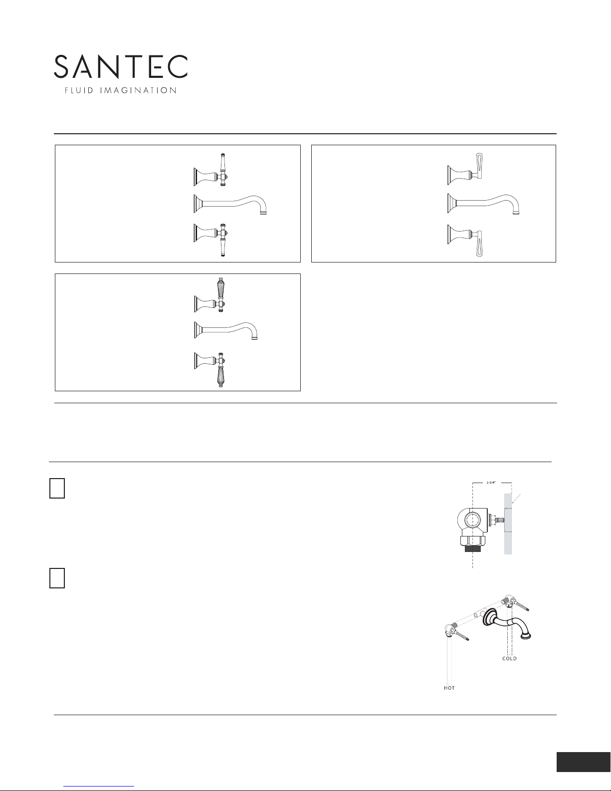
Wall Mount Widespread Lavatory Set
Klassica I Collection
Model Number: 9527KL-TM
Model Number: 9529KL-TM
Klassica Crystal Collection
Model Number: 9527KT-TM
Model Number: 9529KT-TM
Klassica II Collection
Model Number: 9527KR-TM
Model Number: 9529KR-TM
Flush both supply lines before installation, then shut off both supply lines.
Minimum hole size for the spout and handle trim is 1-1/4” and maximum of 1-1/2”
ROUGH INSTALLATION
- Determine where the finished wall will be. This measurement is
1
necessary to accurately plumb in the valve.
- Install the valve making sure that the measurement between the
center of the valve inlet and the outside of the finish wall is 2-3/4”. This
measurement is called the backset.
- Using 1/2” IPS, connect the corner of the valves to the spout
2
base at the desired spread.
- Again, allow no more than 1-1/4” diameter holes for the spout and
handles.
NOTE:
- Where tile construction is planned for the finished walls, allow for
extra thickness dimensions when roughing in the valves.
- Test for proper function before closing walls.
The measurements shown are for reference only. Products and specifications shown are subject to change without notice.
www.santecfaucet.com
|
P: 310.542.0063 F: 310.542.5681
Backset
Finished Wall
Center of Valve Inlet
1/6
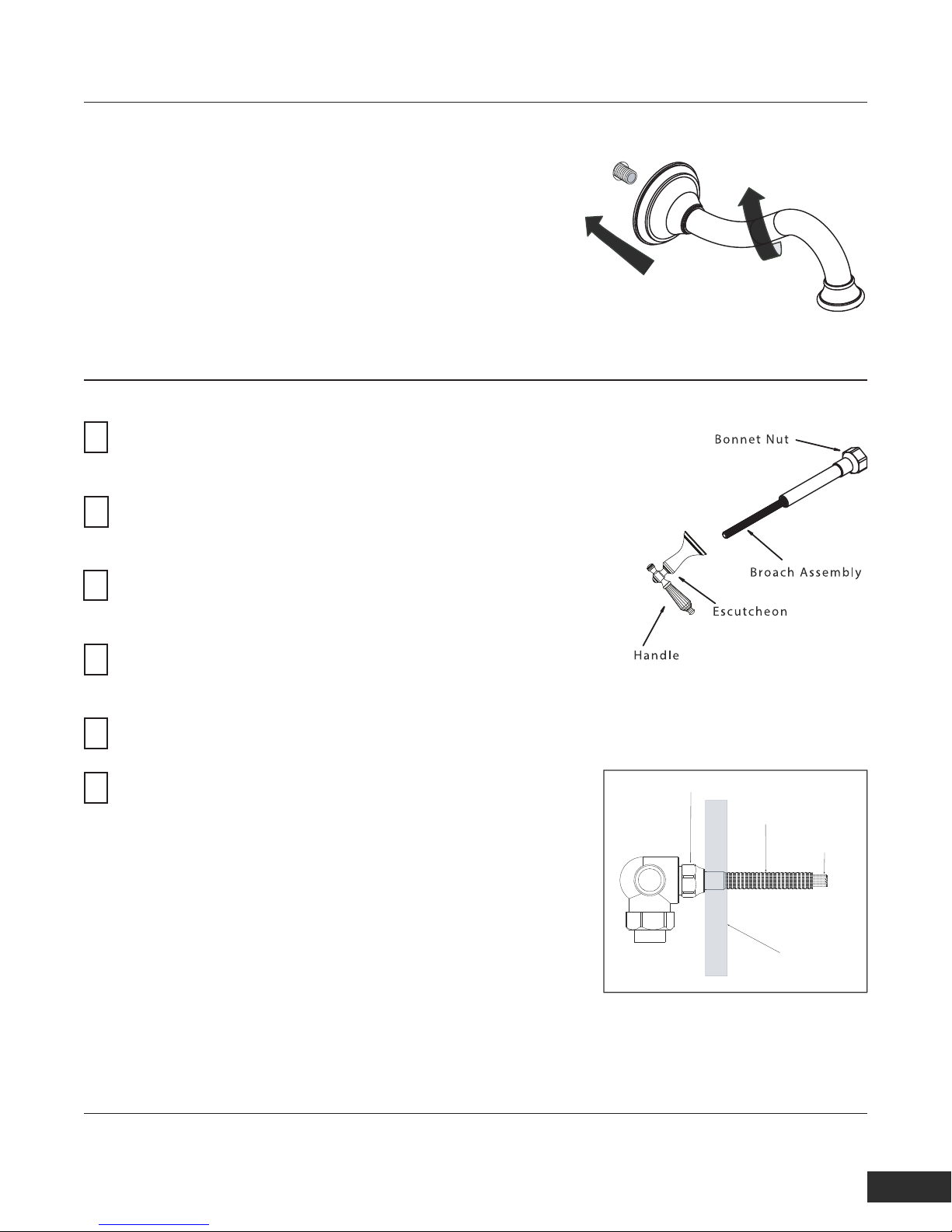
SPOUT INSTALLATION
- Wrap the pipe threading for the spout with teflon tape. Then, thread the spout onto
the pipe until it is secured with the spout facing downward.
NOTE: The length of threaded pipe coming out from the finish wall should be no
longer than 1/2”.
WARNING: Do not use excessive force when threading the spout.
HANDLE INSTALLATION
Thread the bonnet nut, all thread, and insert the broach assembly
1
onto the valve and lightly tighten assembly with a 1” plumber’s
socket Wrench.
Thread the escutcheon completely onto the all thread ensuring
2
the broach properly engages the handle (orientation of the handle
is not important at this point)
Measure the distance remaining between the handle base and
3
wall, remove all trim items from the valve, and cut the excess
distance from the end of the all thread and broach assembly.
Rethread the bonnet nut,all thread, and insert the broach
4
assembly back onto the valve and snugly tighten the assembly
with a 1” plumber’s socket wrench.
Ensure the valve is in the closed position and align the handle to
5
its respective “OFF” Position on the trim.
Thread the escutcheon on the handle onto the all thread and
6
broach assembly ensuring the handle position remains in the
closed position.
Diagram A
Bonnet Nut
All Thread
Bonnet Nut
Finished Wall
The measurements shown are for reference only. Products and specifications shown are subject to change without notice.
www.santecfaucet.com
|
P: 310.542.0063 F: 310.542.5681
2/6
 Loading...