

Santec 708470 User Manual

ITEM NUMBER
708470 __ - __
MODENA COLLECTIONMODENA COLLECTION
SLIDE BAR #7 ASSEMBLY WITH PERSONAL SHOWER #7 SLIDE BAR #7 ASSEMBLY WITH PERSONAL SHOWER #7
1
6
7
2
3
4
5
8
24.8”
Water Inlet
f2.2”
f0.7”
27”
f1 & 1/5”
Part Description# Part #
Base Body with Flange, Slide Bar *
1
Mounting Screw, Shower Slide Bar
WITH CAP ON
3 3/8”
2
Sliding Bar*
3
Sliding Bracket, Sub Assembly*
4
Base Cover-cap, Sliding Bar*
5
Drywall Screw, Mounting Pack
6
Mounting Post Sub Assembly*
7
Spray Assembly, Modena Personal Shower*
8
* Please Specify the finish when you order this part
KEEP THIS INSTRUCTION BOOKLET FOR FUTURE REFERENCE
SL-700-6
PM-928
SL-700-1
SL-700-2
SL-700-7
PM-016
PM-927
PS-700S
PAGE 01
INSTALLATION INSTRUCTIONS
708470_ _
MARKING
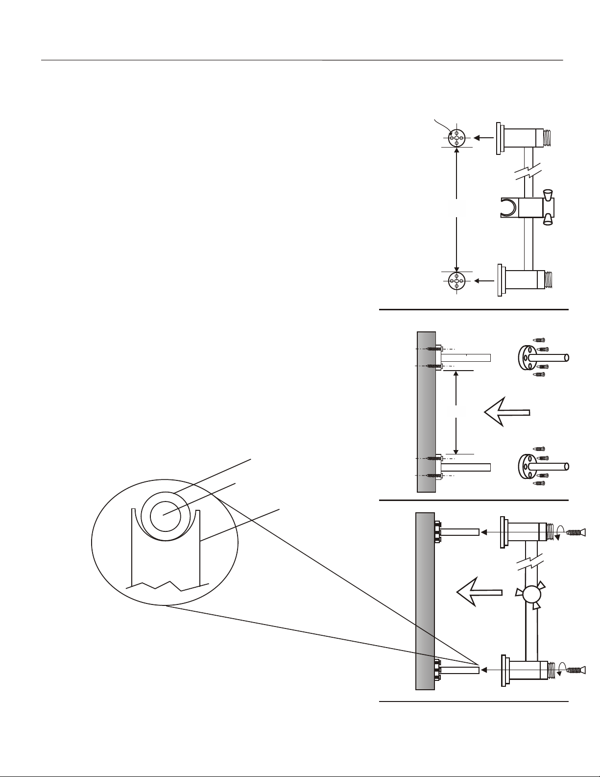
1.
- Mark the vertical distance of 23 and 1/2 inches on the wall.
- This is the distance between the two cylindrical holders at the
two ends of the slide bar.
- Draw two circles having their center as two marked points.
- Try to make them exact circles with defined centers, insert screws
through the four small holes in the pedestal.
- Tighten them firmly.
ASSEMBLY
1.
- Cylindrical holder for the slide bars are assembled with the bar.
- Put mounting screw through the hole in the base body.
This will go into the hole at the top of the mounting post sub
assembly.
- Firmly tighten it.
- Now slide bar and holder assembly (both ends) on the earlier
installed pedestal in such a way so that this assemble in the two
blind holes in the post.
- Align them in such a way so that mounting spindle locates
in the middle.
f 0.235”
23 ½”
ll
23 ½”
Wa
Mounting post
Hole in the post for screws
Slide bar grooved end
ll
Wa
PAGE 02
 Loading...