

Santec 3535TX User Manual
ITEM NUMBER
3535TX _ _-_ _
MODENA COLLECTION
PRESSURE BALANCED TUB/SHOWER SET WITH “TX” STYLE HANDLE
6½”
3 7/8”
22
9¼”
H
C
77
##
S
33
T
55
66
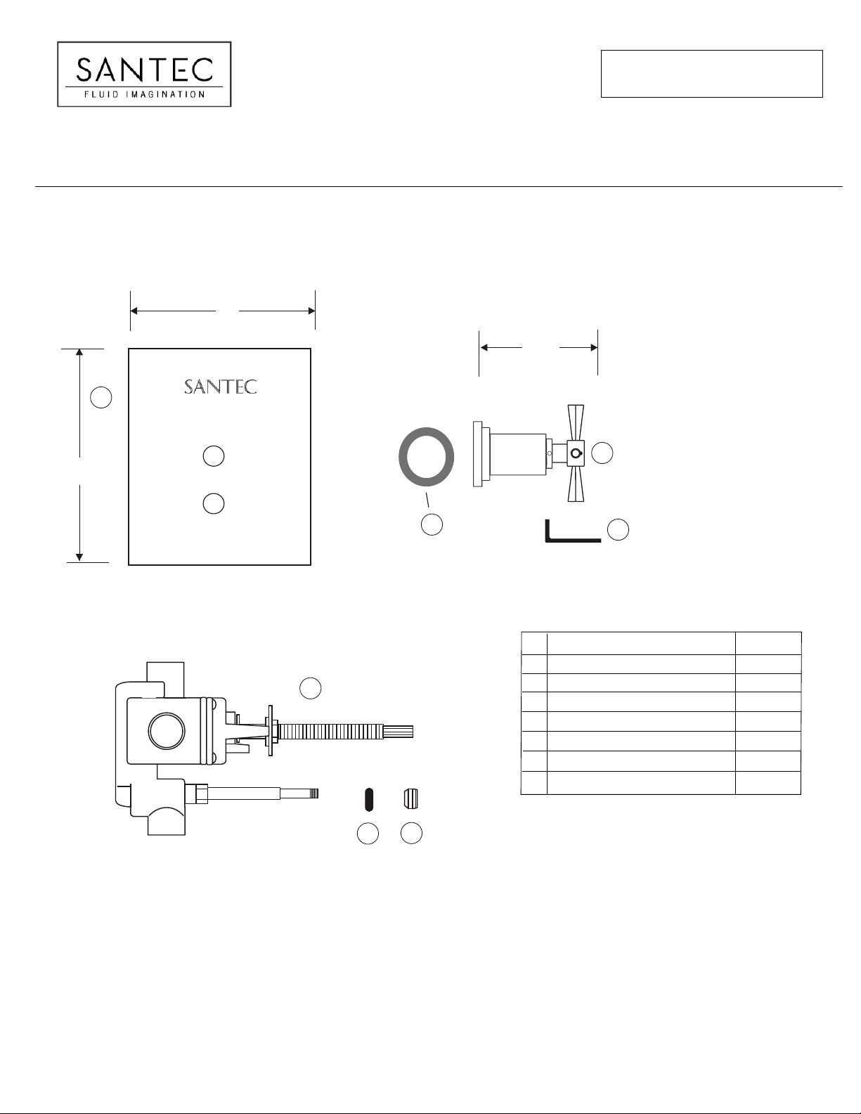
Complete TX Cross Handle for Shower *
1
Pressure Balanced Tub/shower Plate *
2
Pressure Balanced Tub/Shower Valve
3
Allen Key for Set Screw
4
Trim Plate Grommet
5
Diverter Knob *
6
Rubber Washer - flange
7
* Please specify the finish when ordering the part.
11
PART
44
DESCRIPTION
PART #
00YY-TX
PH-28055
PB-3950
PM-033
PM-465
P0-258
PM-400
KEEP THIS INSTRUCTION BOOKLET FOR FUTURE REFERENCE
PAGE 01
INSTALLATION INSTRUCTIONS
3535TX _ _
DESCRIPTION
This product is precision engineered to provide satisfactory performance provided it is installed and operated in
accordance with our recommendations contained in this manual. In order to fully enjoy the comfort, safety and the
reliability of your pressure balancing valve, be certain to familiarize yourself with the contents of this manual.
Shower head
connection
WALL LINE
½”
78"
(1981 mm)
SPECIFICATIONS AND DIMENSIONS
Minimum operating pressure 20 psi
Maximum operating pressure 145 psi
Maximum test pressure 500 psi
Hot and cold water inlets ½" IPS
½”
33"
Shower outlet ½" IPS
Flow capacity 5 USGPM@ 50 psi
Finished wall adjustment : see Illustration B
FLOOR
LINE
INSTALLATION
NOTE: Failure to follow these instructions may cause damage or improper operations and nullify the warranty.
ROUGH IN
- Make sure the water supplies are off.
- Remove all the trim items (plate, handle and flange) before installation.
- Secure the valve firmly against the stud. Make sure the ½" shower outlet is in the up position.
- Make sure to flush or raise grouting on the tiled wall surface.
- Adjust the All Thread depth against the Teflon Washer and Limit Stop.
Screw the All Thread against the Teflon washer until it is pressured gently against each other.
- Tighten firmly the Lock Nut against the Lock Plate.
- Position the valve using the dimension shown in the illustration B.
3.00”
Trim Plate
FLANGE WASHER HANDLE FLANGE
HANDLE BELL
HANDLE
S
All Thread
Stem
Lock Nut
Lock Plate
Diverter Knob
T
Diverter Rod
Diverter Rod O-Ring
ILLUSTRATION B
PAGE 02
 Loading...