

Santec 1850NX User Manual
REVERE COLLECTION
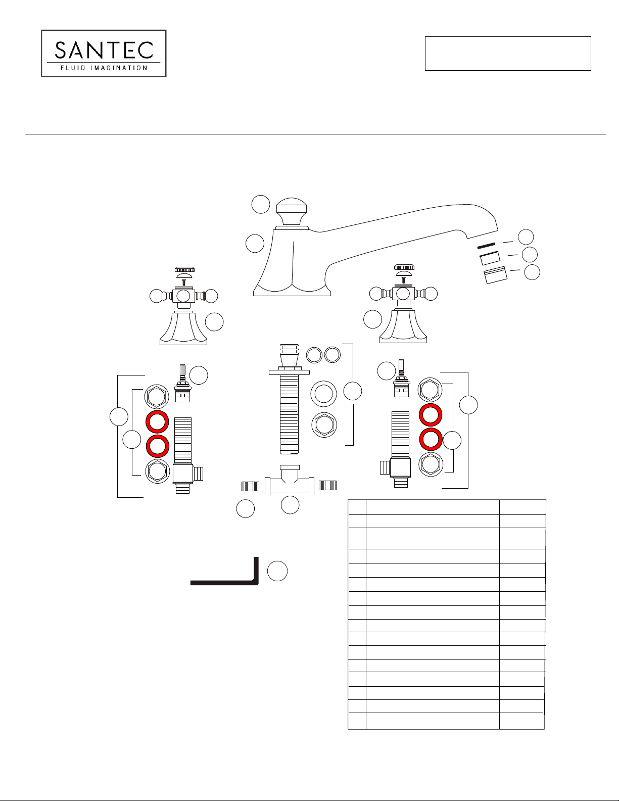
ROMAN TUB FILLER WITH “NX” HANDLES
33
ITEM NUMBER
1850NX _ _-_ _
88
55
66
22
1111
11
1515
1010
22
77
44
99
55
##
Complete Spout Assembly *
1
Complete NX Cross Handle
2
Spout Knob *
3
Quick Connect Spout Shank & Hardware
4
Valve Body Mounting Hardware
5
Hot Cartridge
6
Cold Cartridge
7
Complete Hot Valve
8
9
Complete Cold Valve
10
Tee Connector
11
All Thread
12
Aerator Washer
13
Roman Tub Aerator without Restrictor
Aerator Housing *
14
15
Large Allen Key for Roman Tub Spout
* Please specify the finish when ordering the part.
PART
DESCRIPTION
Assembly *
1212
1313
1414
PART #
PS-5R00S
00-NX-C cold/right
00-NX-H hot/left
P0230
KQ-5000S
P0416-LH
P0416-LC
P0493
P0494
P0340
P0341
PM-356
PM-355
P0255L
KEEP THIS INSTRUCTION BOOKLET FOR FUTURE REFERENCE
PAGE 01
INSTALLATION INSTRUCTIONS
FLUSH BOTH SUPPLY LINES BEFORE INSTALLATION
AFTER FLUSHING, SHUT OFF BOTH SUPPLY LINES
MINIMUM HOLE SIZE FOR THE SPOUT AND HANDLE TRIM IS 1 1/4” AND MAXIMUM IS 1 1/2”
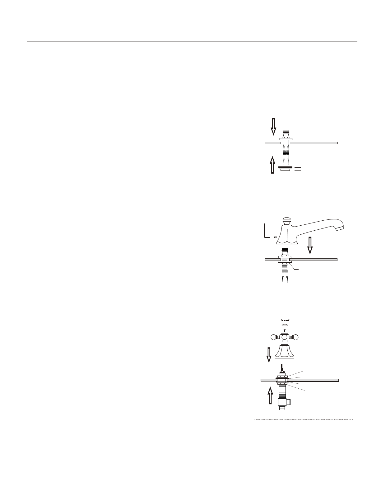
SPOUT INSTALLATION
1
- Remove the Quick Connect Spout Shank and Mounting Hardware from the box.
Remove the mounting hardware (metal washer and brass lock nut) from the Quick Connect
Shank.
- From the top of the deck, slip the quick Connect shank with the brass plate through the
assigned spout hole.
- Secure the quick connect shank by putting the washer and locknut back on the shank.
Tighten the lock nut firmly.
2.
- Remove the faucet from the box.
- From the top of the deck, slip the spout (1) onto the quick connect shank top.
Align the spout and tighten the set screw with the Large Allen Key (15) provided..
- Connect the spout shank to one of the outlet port of the handle valve bodies after the handle
trims and valve bodies are installed. **
Large Allen Key
Brass plate
Metal washer
Brass lock nut
1850NX _ _
Note: for better installation it is advisable to place silicone caulking around all holes on the top
of the deck
If the trim is ordered separately, please keep the shank protector on the quick connect shank
at all time to avoid damages to the unit.
HANDLE INSTALLATION
1.
- Remove the pre-assembled trim(2) from the valve bodies. First the cap, then button, screw,
handle bell and last the top lock nut and fiber washer.
- Slip the valve body (8) or (9) up from the bottom of the tub through the appropriate hole next
to the spout.
- From tub top, insert the top mounting hardware back onto the valve. Do not tighten.
screw the handle bell of the handle trim (2) back onto the valve body. Adjust the height of the
handle bell against the top lock nut. Make sure the handle bell is flushed against the surface.
Insert the handle onto the stem and secure it with the screw. Tighten the screw firmly.
Insert the porcelain button (”COLD” on the right handle bell and “HOT” on the left handle bell.
Align the lettering and secure it using with the handle cap. Tighten it firmly.
Make sure that the handle turns freely in both directions.
2
- Position the valve body side outlet towards the tee connector (10) for easier pipe connection.
Align the handle lever and tighten lock nut (5) firmly. Repeat the same procedure for the opposite side.
- Connect the water supply lines to the bottom inlets of the valve bodies. **
- Connect the valve body side outlet to the tee connector (10). **
Metal washer
Brass lock nut
Handle Cap
Button
Screw
Handle
Handle Bell
Brass lock nut
Fiber washer
Fiber washer
Brass lock nut
** The spout, handle valve bodies and tee connector can be connected with flex hoses (not provide by Santec) or copper pipe
soldering. Please note that when soldering connections, do not use excessive heat. Excessive heat can damage the joints
increasing possibility of leakage.
PAGE 02
 Loading...