

Page 1
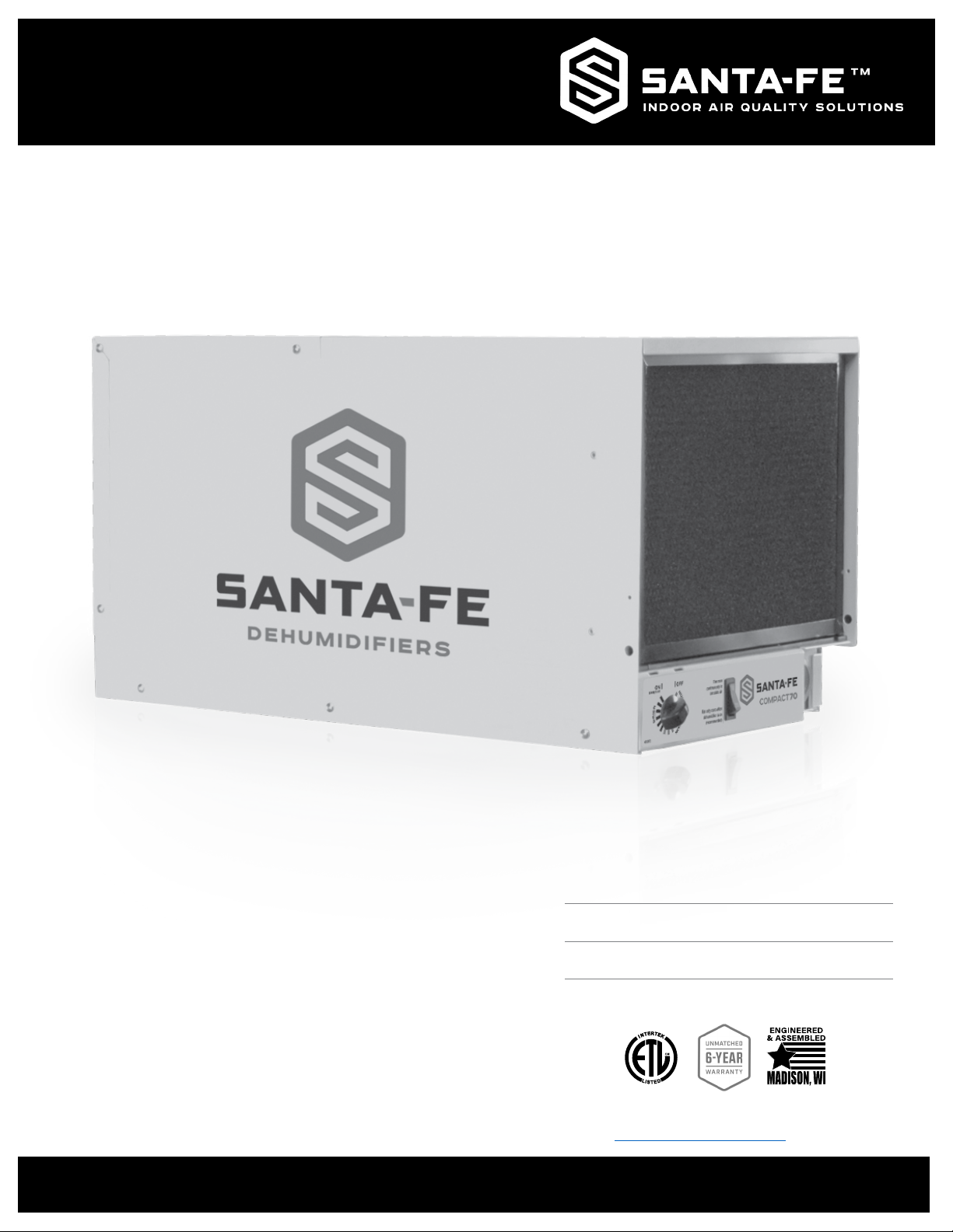
COMPACT SERIES | COMPACT 70
Installation & Operation Instructions
The Santa Fe Compact70 is designed for
superior basement and crawl space
dehumidication. Tight spaces are no problem
for the Santa Fe Compact70 dehumidier. Its
compact size works perfect in low crawl spaces
and small basements without sacricing power
and performance. Designed to t in a variety of
small spaces, the Compact70 provides multiple
installation options for greater flexibility.
Santa-Fe-Products.com | 800.533.7533
Serial Number
Install Date
Sold By
Patent: thermastor.com/patents
TS-1101 02/22 Rev D
Page 2

Table of Contents
Safety Instructions ..................................................................................3
Intended Applications ................................................................................3
Registrations ..............................................................................................3
Dehumidier Set Up ................................................................................. 4
Items Included In Box.................................................................................4
Important Precautions ...............................................................................4
Location Considerations ............................................................................4
Installing Leveling Feet ..............................................................................4
Drain Installation .....................................................................................5
Operation ................................................................................................6
Humidity Control Adjustment ....................................................................6
Defrost Cycle ..............................................................................................6
Fan Operation .............................................................................................6
Air Filtration ............................................................................................7
Changing The Filter ....................................................................................7
Ducting to Finished Areas (Optional) ........................................................8
Attaching Duct Collars ...............................................................................8
Recommended Installations ......................................................................9
Service ..................................................................................................10
Troubleshooting ...................................................................................... 10
Refrigerant Charging ............................................................................... 11
Compressor / Capacitor Replacement ................................................... 11
Electrical Requirements .........................................................................12
Warranty ................................................................................................13
4201 Lien Rd. Madison, WI 53704
www.Thermastor.com | www.Santa-Fe-Products.com
1-800-533-7533
© 2016 Therma-Stor LLC
Page 3
Safety Instructions
READ THE INSTALLATION, OPERATION AND MAINTENANCE INSTRUCTIONS CAREFULLY BEFORE
INSTALLING AND OPERATING THIS DEVICE. PROPER ADHERENCE TO THESE INSTRUCTIONS IS
ESSENTIAL TO OBTAIN MAXIMUM BENEFIT FROM YOUR SANTA FE DEHUMIDIFIER.
WARNING!
THIS SYMBOL MEANS IMPORTANT INSTRUCTIONS. FAILURE TO HEED THEM CAN RESULT IN SERIOUS
INJURY OR DEATH.
CAUTION!
THIS SYMBOL MEANS IMPORTANT INSTRUCTIONS. FAILURE TO HEED THEM CAN RESULT IN INJURY OR
MATERIAL PROPERTY DAMAGE.
• Never operate a unit with a damaged power cord. If the power cord is damaged, it must be replaced by the manufacturer,
its service agent, or a similarly qualied person in order to avoid a hazard.
• Do not unplug the unit by pulling on the cord. Grasp the plug rmly and pull it out of the wall socket or power receptacle.
• When plugging in the unit, use a Ground Fault Interrupter outlet.
• This appliance is not intended for use by persons (including children) with reduced physical, sensory or mental
capabilities, or lack of experience or knowledge, unless they have been given supervision or instruction concerning the
use of the appliance by a person responsible for their safety. Children should be supervised to ensure that they do not
play with the appliance.
• Never operate electrical equipment near or in standing water.
• Do not stick your ngers or other objects through the safety grill.
• The unit must be used in the upright position.
• When changing lters, do not stick ngers or other objects in the unit and make sure the dehumidier is off.
• Do not restrict airflow in to or out of the unit. This may cause the unit to overheat.
• The unit should never be serviced or cleaned while it is plugged in.
• Do not sit or stand on the unit, or use as a shelf or table.
• Before leaving the unit unattended, ensure children do not have access to the equipment. Do not allow children to play
with or near the unit or in its air flow.
• The unit is designed to be installed indoors only.
• Contact installer or call 1-800-533-7533 for all repair or warranty needs.
Intended Application(s)
The Santa Fe Compact70 is intended for use in crawl spaces or basements: however, the unit can be placed in almost any
residential setting where dehumidication is desired. Use in non-residential applications and pool areas may void warranty.
The Santa Fe Compact70 is designed to operate in temperatures between 49° and 95°F. This unit works most effectively
between 56° and 95°.
In order to efciently control humidity levels, the area in which the dehumidier is to be operated must be free of water
intrusion or excessive fresh (outside) air inltration. Before installing the Santa Fe Compact70, water intrusion and air
inltration problems should be addressed.
Registrations
The Santa Fe Compact70 conforms to unied standard UL 60335-2-40 and CSA standard C22.2.60335-2-40.
800.533.7533 | Santa-Fe-Products.com Santa Fe Compact70 Installation & Operation Instructions
3
Page 4
Dehumidier Set Up
ELECTRICAL SERVICE
ACCESS THIS SIDE
9' POWER CORD
TOP VIEW
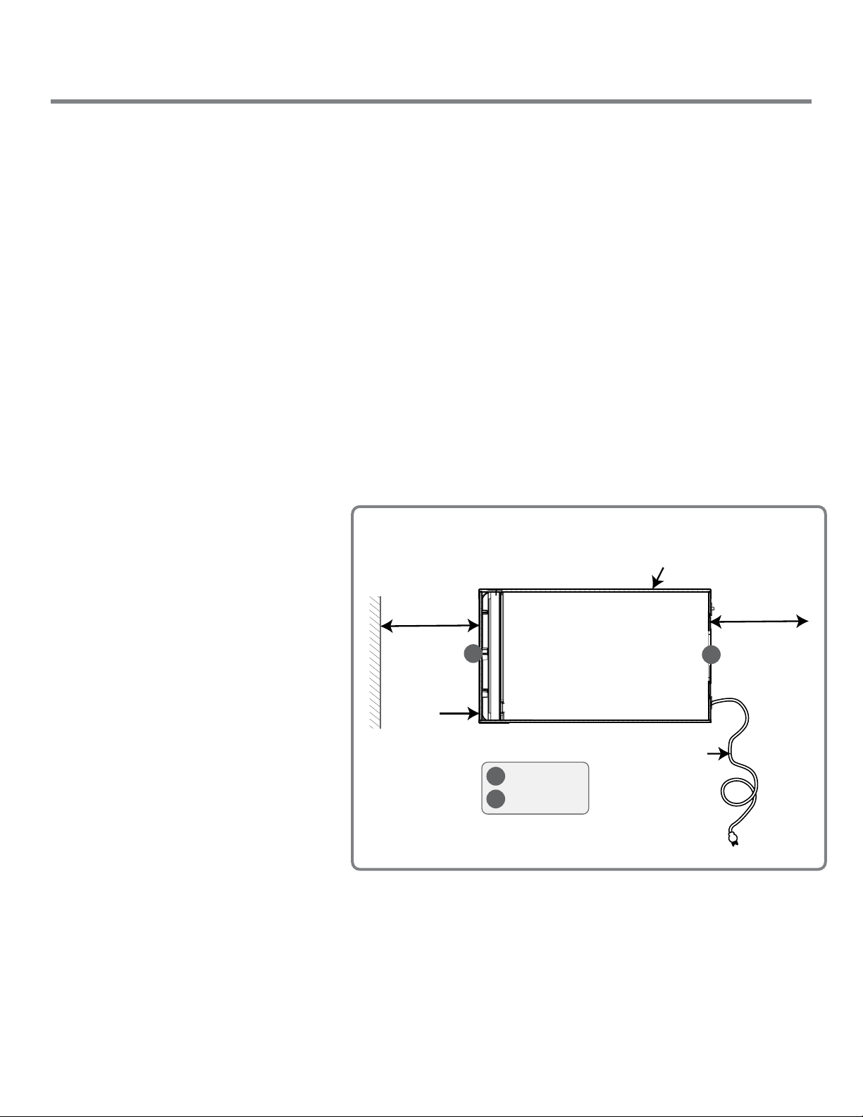
MINIMUM
CLEARANCE
FOR FILTER
REMOVAL
AND PROPER
AIR FLOW
11"
B
RETURN AIR
SUPPLY AIR
A
B
A
DRAIN
ACCESS
MINIMUM
CLEARANCE
FOR PROPER
AIR FLOW
24"
Items Included in Box:
• Santa Fe Compact70 Dehumidier
• Santa Fe Compact70 Installation & Operation Instructions
• Santa Fe Compact70 Leveling Feet
• 8' Drain Hose
• Drain Adapter
• Merv-13 Filter (Dimensions: 0.75” x 9.00” x 11.38”) and Pre-Filter
• 2 Compressor Shipping Strap Plugs – Not used for the Compact70
Important Precautions
• Do not install the Santa Fe Compact70 with the intake or exhaust of the unit within 1' of a wall or other obstruction. Avoid
directing the discharge air at people. The dehumidier should be used in the upright position.
• Do not place the unit where curtains or debris can be drawn into the intake and restrict airflow.
• The device is designed to be installed indoors in a space that is protected from rain and flooding.
• Do not operate in standing water or place the unit near open water. If used near a water source; be certain there is no
chance the unit could fall into the water or get splashed and that it is plugged into a dedicated circuit and Ground Fault
Circuit Interrupter (GFCI) protected outlet.
• Install the unit with enough space to access all sides for maintenance and service. The entire shell needs to be removed
in order to do repairs.
• DO NOT use the dehumidier as a bench or table.
• DO NOT place the dehumidier directly on structural building members without vibration absorbers or unwanted noise
may result. Place the Santa Fe Compact70 on supports to raise the base of the unit.
Location Considerations
• Locate the dehumidier near a suitable drain
(8' drain hose included). Allow for proper
drainage and routing of needed drain pipes.
• Locate the dehumidier in an area where the
cord’s length (9') easily reaches a 115 VAC
electrical outlet with a minimum of a 15 Amp
circuit capacity.
• The unit is designed to operate while level. If
the unit is placed on an unlevel surface, refer
to section below (Installing Leveling Feet).
Failure to level the unit may result in leakage
or improper drainage.
• The unit should be suspended with a hang kit
from the floor joists if there is any possibility
of flooding. A flooded unit is not covered by
warranty. Feet will be installed as a securing
measure after the hang kit is put on the
dehumidier. DO NOT hang the Santa Fe
Compact70 from its’ cabinet.
• Allow sufcient clearance to handle the unit’s
overall dimensions as well as any optional
return and supply ductwork to the unit.
• Allow sufcient clearance for lter removal
and to prevent airflow obstruction.
• Electrical service access will require the removal of the outside shell. Allow sufcient clearance around the unit.
Installing Leveling Feet
• Lay down a protective pad (pillow, blanket, etc.).
• Carefully turn unit onto side.
• Install leveling feet and adjust to the desired position to ensure unit is level for proper drainage.
• Carefully bring unit to upright position.
• Wait a minimum of 10 minutes before operating.
Santa Fe Compact70 Installation & Operation Instructions Santa-Fe-Products.com | 800.533.7533
4
Page 5
Drain Installation
The Santa Fe Compact70 generates condensate.
Place a secondary drain pan under the dehumidier if it is suspended above a nished area or above an area where water leakage could cause damage.
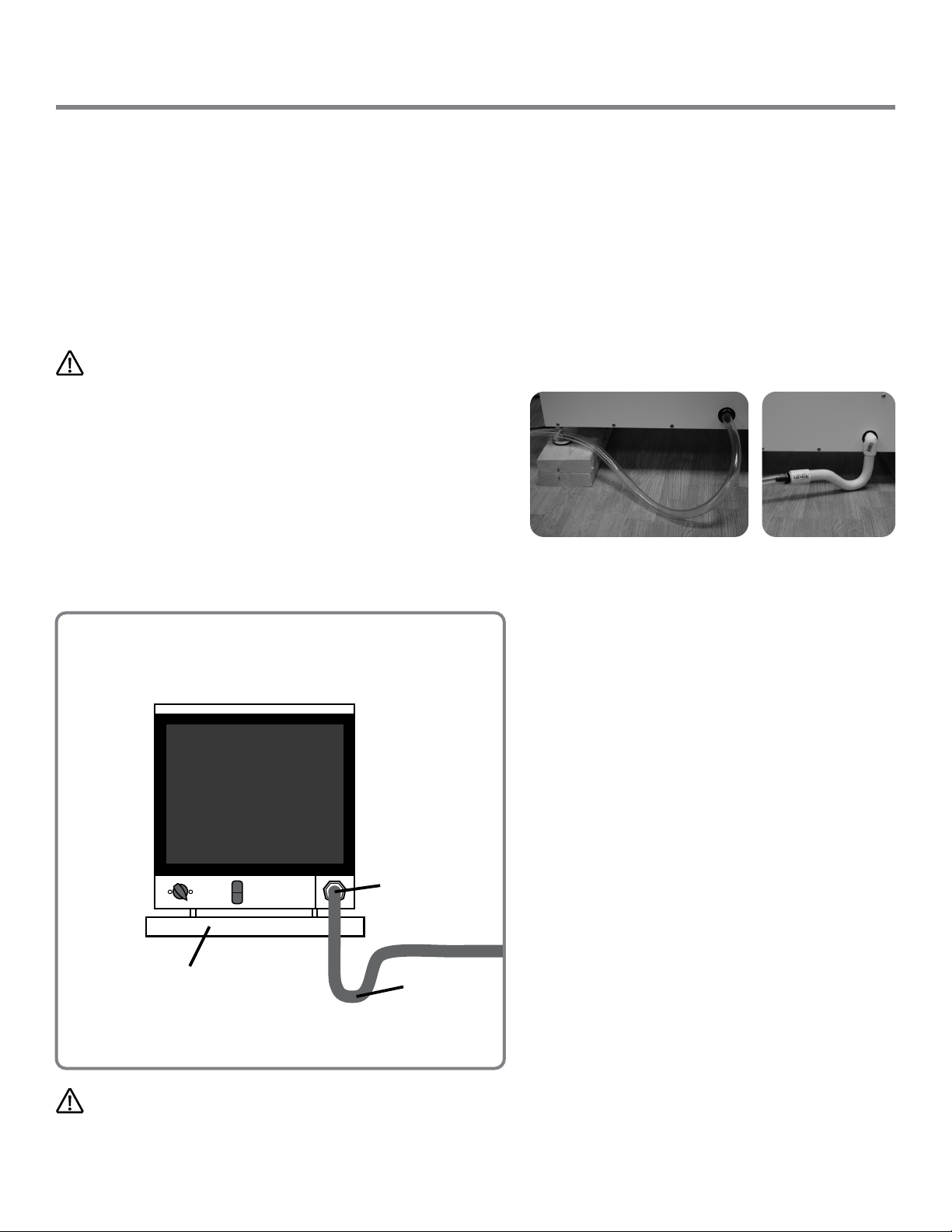
A drain trap is required for the dehumidier to run properly. Install a 3/4" threaded male NPT adapter to the drain or
drain pan if one is being used. Install a drain pipe assembly utilizing 3/4" PVC pipe to transport the condensate to a
drain. Pitch of drain should be 1" per 10'.
An optional condensate pump kit is available for use with the Santa Fe Compact70 and may be installed if lift is required
to dispose of condensate. Condensate is automatically pumped to a remote location when the water level in the pump’s
reservoir rises to close the float switch.
CAUTION!
The Santa Fe Compact70 requires a drain trap. Creating a drain
trap allows a small amount of water to build up in the trap area
of the clear hose. This prevents air from back flowing through
the hose and into the dehumidifier; essentially causing the unit
to backflow water out of the corners of the machine. Position the
trap in the hose approximately 8"-10” from the dehumidifier and
make sure the highest point of the trap is still at least 2” below
the black drain port adapter on the dehumidifier. If the highest
point of the trap is above the drain port, water will back flow into
the dehumidifier. Check the hose regularly to ensure water is
draining properly.
Drain Installation
Front View
Drain Port
Floor Bend PVC Trap
PVC materials available from your local hardware store.
Use care to keep the hose as flat to the floor as
possible after your trap is in place. Be sure the hose is
not kinked or otherwise restricted so water can pass
through the hose freely. Improper installation of the
drain hose may result in water leakage.
If the Santa Fe Compact70 is located too far from the floor
drain and the provided hose does not reach, you may use
a 1/2 PVC rigid pipe that will fit inside the 3/4 hose as a
means to extend the drain line. Rigid PVC tubing is readily
available from your local hardware store. Be sure the
extension is at a down-word slope to the drain.
An optional condensate pump kit may be installed if
lift is required to remove condensate. To order,
contact your local dealer or visit our website at
www.santa-fe-products.com. You may also reach
us by phone at (800) 533-7533 and we can direct you
to a dealer.
Secondary Drain Pan (Optional)
Note: The secondary drain pan is only needed if the
dehumidifier is located above a living space.
Drain Trap
CAUTION!
CHECK DRAIN HOSE WHEN CHANGING FILTER TO ENSURE THERE IS NOT BUILD UP OF ALGAE OR SLUDGE.
800.533.7533 | Santa-Fe-Products.com Santa Fe Compact70 Installation & Operation Instructions
5
Page 6
Operation
Humidity Control Adjustment
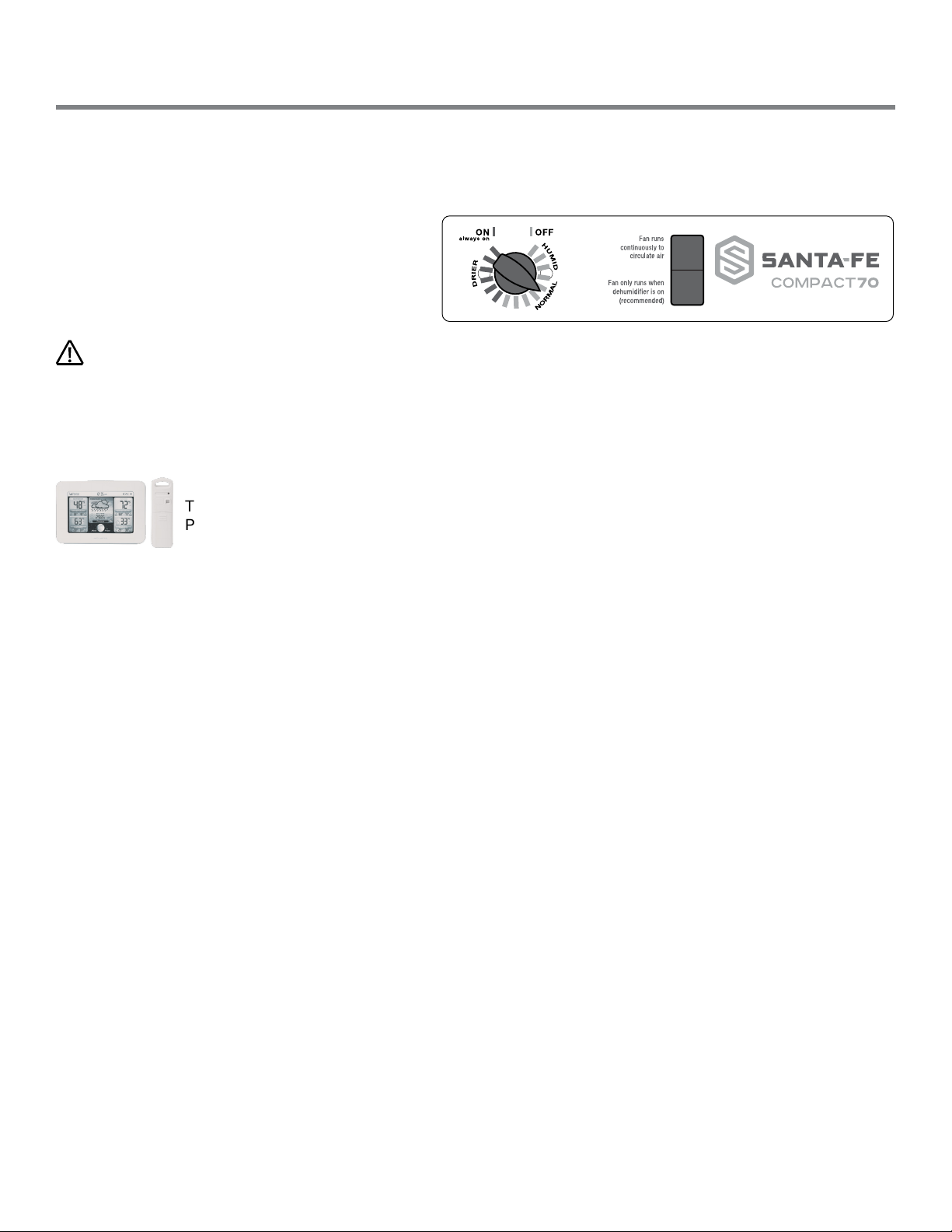
The humidity control is an adjustable switch that turns the dehumidier on and off. It turns on when the relative humidity
(RH) rises to the dial set point. It turns off when the RH is within ±5% of the set point.
Approximate Humidity Levels Per Setting
“Drier” 35% to 45% Relative Humidity
“Normal” 45% to 55% Relative Humidity
(Recommended for most applications)
“Humid” 55% to 65% Relative Humidity
CAUTION!
The dehumidier will run continuously until the RH is reduced to the humidity control dial setting. It is not recommended to
set the humidity control to “dry” in rooms under 65°; doing so will result in long periods of ineffective dehumidier run time.
To turn unit on, turn the humidity dial clockwise to the recommended “NORMAL” position and set fan control to “FAN AUTO.”
To turn the unit off, turn the humidity dial counter clockwise to the “OFF” position and set fan control to “FAN AUTO.”
The Acurite Hygrometer (part number 4038844) is available to accurately monitor humidity levels.
Please contact your dealer or order online.
On
Auto
Defrost Cycle
This product includes a defrost thermostat. This feature prevents internal damage caused by excessive frost forming
within the unit. When the unit is experiencing excessive frost the system will stop dehumidfying and the fan will run until
normal operating conditions are present.
Fan Operation
Turning the fan switch “FAN ON” will cause the unit’s internal blower to run continuously, whether the unit is
dehumidifying or not. This function is desirable if the unit is used for air circulation or ltration. Turning the fan
switch to “FAN AUTO” (recommended) will cause the unit’s internal blower to run only while the unit is dehumidifying.
Santa Fe Compact70 Installation & Operation Instructions Santa-Fe-Products.com | 800.533.7533
6
Page 7
Air Filtration
The Santa Fe Compact70 is equipped with a pre-lter and a MERV-13 air lter (89-90% ASHRAE dust spot). An optional
MERV-8 or MERV-11 lter is available at www.thermastorlters.com. The lters should be checked and replaced every
three to six months. Operating the unit with a dirty lter will reduce dehumidier capacity and efciency.
DO NOT operate the unit without a MERV-8, MERV-11 or MERV-13 lter. Filter non-compliance voids the product warranty.
CAUTION!
MAKE SURE UNIT IS OFF BEFORE CHANGING THE FILTER. FAILURE TO FOLLOW FILTER HANDLING INSTRUCTIONS MAY
RESULT IN IMPROPER FUNCTION OF THE DEHUMIDIFIER AND CAUSE PREMATURE FILTER WEAR OR UNIT DAMAGE.
Changing the Filter
For greatest ltration and efciency of the Santa Fe Compact70, it is recommended the air lters be replaced
every three to six months.
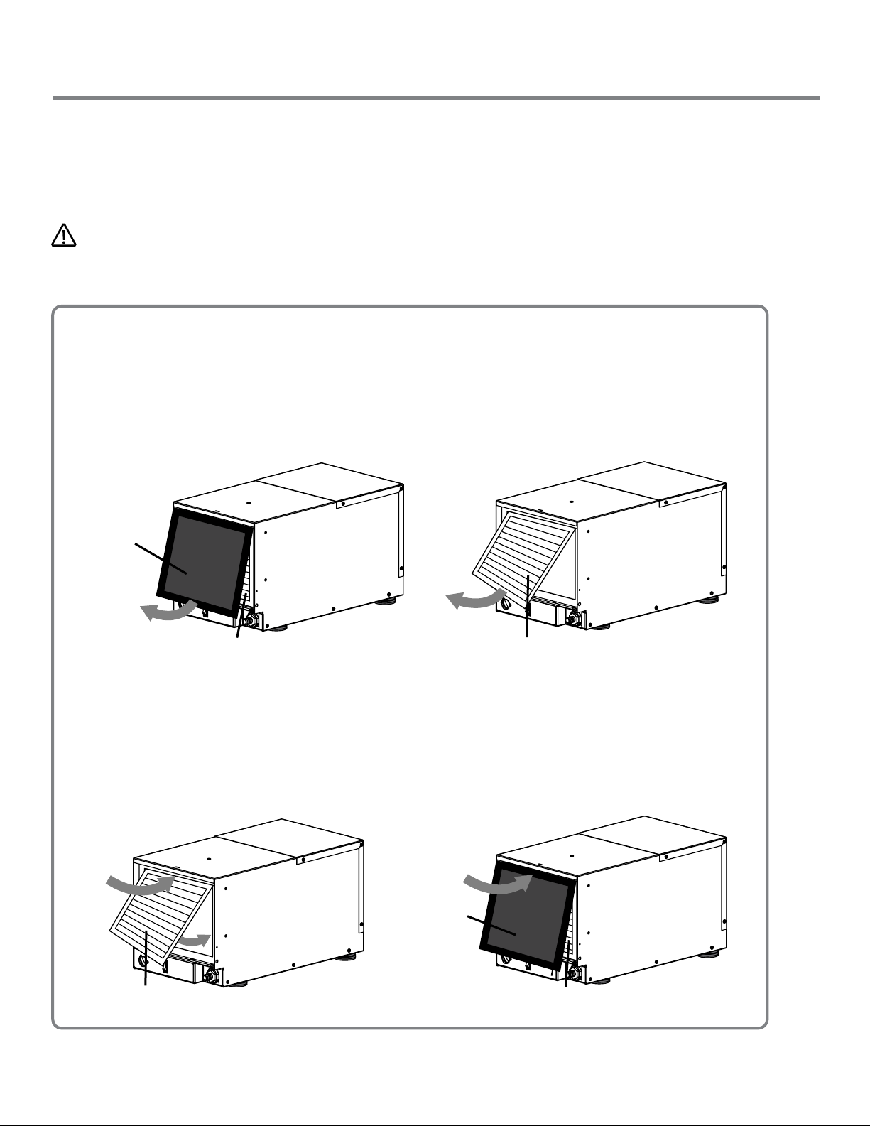
Step 1 - Removing the Filters:
Remove the 1/4" pre-lter by gently pulling on the bottom of the lter frame.
Remove the MERV-13 lter by gently pulling on the bottom of the lter frame.
Pre-Filter
MERV-13 Filter MERV-13 Filter
Step 2 - Installing the Filters:
Angle the top of the MERV-13 lter and gently slide the lter into the lter slot. Do not force. If resistance is
felt, check alignment for obstructions or debris inside the lter housing. Be sure the arrows on the lter are
facing into the dehumidier.
Angle the top of the pre-lter and gently slide the lter into the lter slot (in front of the MERV-13 lter).
Do not force. If resistance is felt, check alignment for obstructions or debris inside the lter housing.
Pre-Filter
MERV-13 Filter
800.533.7533 | Santa-Fe-Products.com Santa Fe Compact70 Installation & Operation Instructions
MERV-13 Filter
7
Page 8
Ducting To Finished Areas (Optional)
Front View
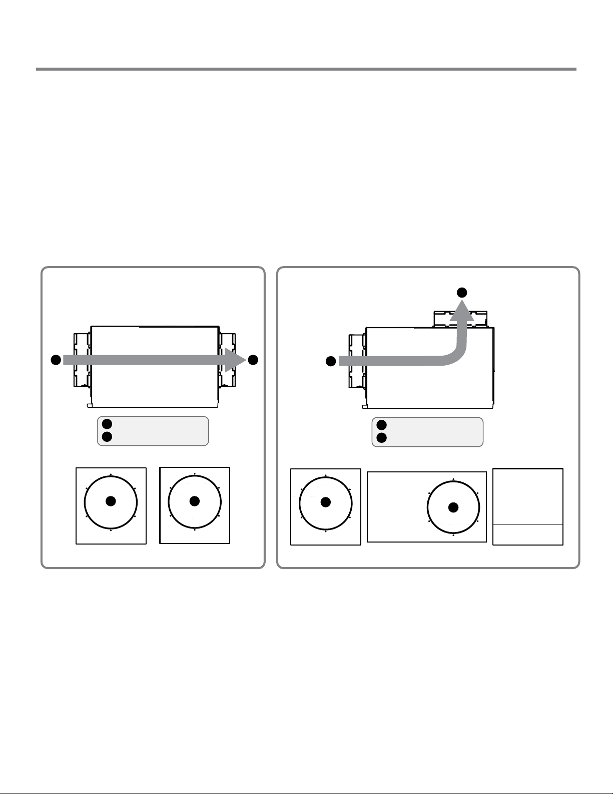
Horizontal Flow Through
(End Discharge)
Rear View
Vertical Flow Through
(Top Discharge)
8" Return Air Inlet
8" Supply Air Outlet
A
B
A
A
B
A
8" Return Air Inlet
8" Supply Air Outlet
A
B
Top View
Front View
A
Rear View
B
B
Air Flow
Air Flow
B
Vertical Flow Through
(Top Discharge)
A
8" Return Air Inlet
8" Supply Air Outlet
A
B
Top View
Front View
A
Rear View
B
Air Flow
B
Attaching Duct Collars
Return Air Inlet
An 8” diameter duct collar and a front panel are attached to the unit.
Supply Air Outlet
The back panel of the dehumidier can be rotated to allow for horizontal flow through or vertical flow through of the
supply air.
• Horizontal Flow Through
The unit ships congured for a horizontal flow through. An 8" diameter duct collar is attached to the unit.
• Vertical Flow Through
Remove the exhaust panel. Rotate the panel so the exhaust collar is located on the top of the unit. Align screw holes
and snap the panel onto the base. Secure the exhaust panel to the base by replacing the six screws.
Santa Fe Compact70 Installation & Operation Instructions Santa-Fe-Products.com | 800.533.7533
8
Page 9
Ducting To Finished Areas (Optional)
Passive Return Vent
1
2
Optional Wall
Mount Dehumidistat
(mounts on opposite wall in finished area)
3
Supply Grill
4
Supply/Discharge
Duct Work
Installation of a
Santa Fe Compact2 With a
Supply Duct Kit Only
Unfinished Area
F
i
n
i
sh
e
d
A
r
e
a
Un
f
ini
s
h
e
d
A
rea
3
4
1
2
Return/Intake
Duct Work
6
1
Return Grill
3
Supply Grill
Supply/Discharge
Duct Work
Installation of a
Santa Fe Compact2 With a
Supply Duct Kit Only
Unfinished Area
F
i
n
i
sh
e
d
A
r
e
a
Un
f
ini
s
h
e
d
A
rea
1
3
4
2
5
Optional Wall Mount
Dehumidistat (mounts on
opposite wall in finished area)
2
Passive Return Vent*
5
4
6
Recommended Installations
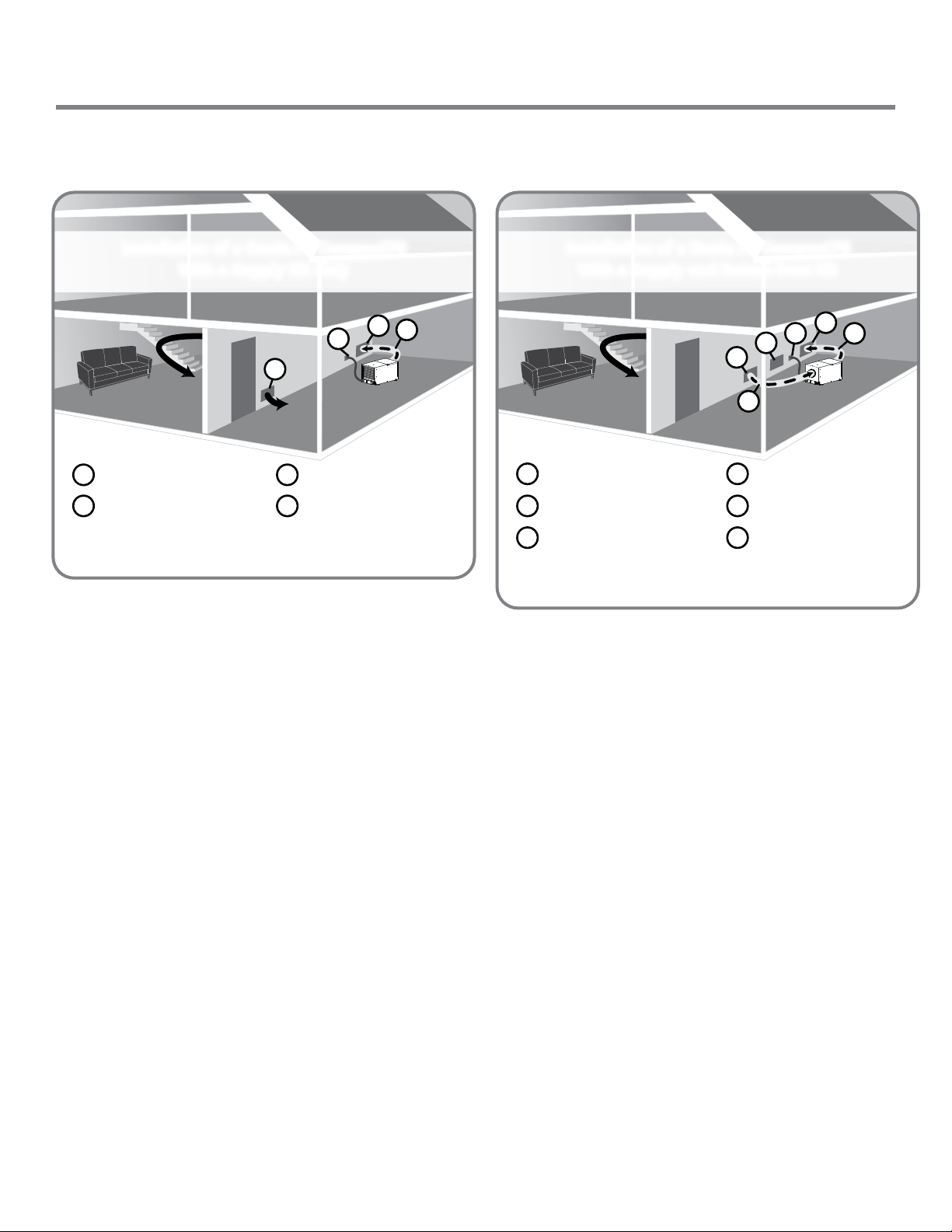
Installation of a Santa Fe Compact70
With a Supply Kit Only
• Place the Santa Fe Compact70 in the unnished area
of the basement, near a drain access (condensate will
drain via gravity or with an optional pump kit).
• Using the supply duct collar, supply the dry air from
the dehumidier into a large, open area in the nished
section of the basement.
• Place a return grill / passive vent on the other side of
the wall that separates the nished and unnished
areas. This will allow for a circular air flow throughout
the basement.
• The passive grill will prevent the unnished room from
being placed under a negative pressure and also allow
the dehumidier to focus on keeping the unnished
area dry as well.
• The onboard dehumidistat control can be used on the
unit for this application or a 120 volt dehumidistat
can be placed in the nished basement as well (we
recommend using an electrician to run the wiring).
• Be sure to keep all doors open to any other rooms in the
basement to help with proper air circulation (bedrooms,
bathrooms, etc.)
Installation of a Santa Fe Compact70
With a Supply and Return Duct Kit
• Place the Santa Fe Compact70 in the unnished area of
the basement, near a drain access (condensate will drain
via gravity or with an optional pump kit).
• Using the supply and return duct kit, supply the dry air
from the dehumidier into a large, open area of the nished basement. Use the return duct kit to draw air back
through the dehumidier.
• Be sure the return and supply are at least 10 feet away
from each other for proper air flow throughout the
basement. Add a passive grill between the nished and
unnished areas (*or have a 2” gap under the door
separating the two rooms). This will help keep the
unnished area dry as well.
• Use the 120 volt, wall mounted dehumidistat for this
installation for proper run time on the dehumidier
(we recommend using an electrician to install the
separate 120 volt control).
• Be sure to keep all doors open to any other rooms in the
basement to help with proper air circulation (bedrooms,
bathrooms, etc.)
800.533.7533 | Santa-Fe-Products.com Santa Fe Compact70 Installation & Operation Instructions
9
Page 10
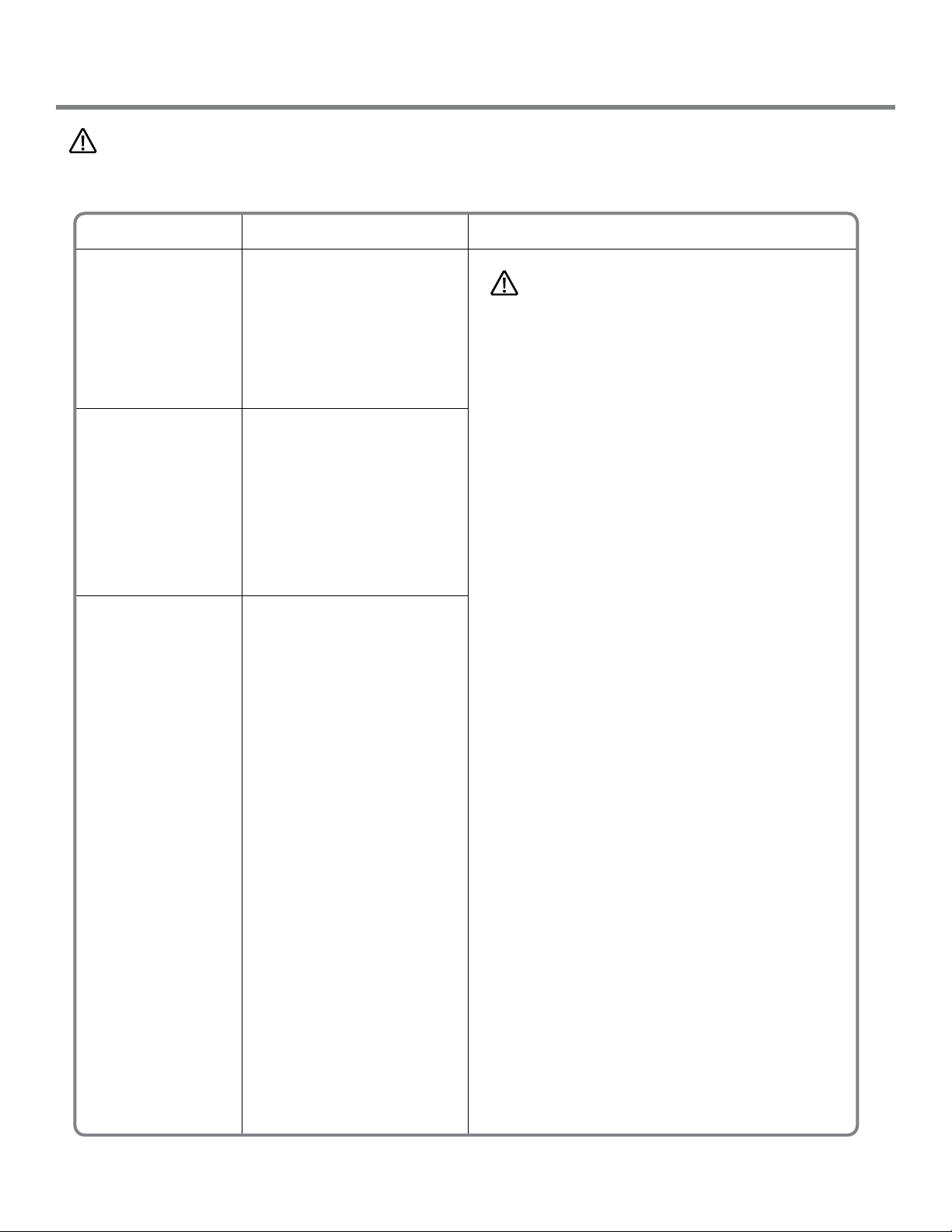
Service - Troubleshooting
CAUTION!
TROUBLESHOOTING SHOULD BE PERFORMED BY A QUALIFIED HVAC TECHNICIAN.
Symptom Possible Reason Troubleshooting Procedure
Fan is not running.
Dehumidication
or fan is being
called for.
Low dehumidication
capacity (evaporator
is frosted
continuously).
Dehumidication is
being called for.
Dehumidier
removes some
water, but not as
much as expected.
1. Loose connection in
fan circuit.
2. Obstruction prevents
fan impeller rotation.
3. Defective fan.
4. Defective fan relay.
1. Defrost thermostat loose
or defective.
2. Low refrigerant charge.
3. Dirty air lter(s) or air flow
restricted.
4. Excessively restrictive
ducting connected to unit.
1. Air temperature and/or
humidity have dropped.
2. Humidity meter and or
thermometer used are
out of calibration.
3. Unit has entered defrost
cycle.
4. Dirty air lter(s) or air flow
is restriced.
5. Defective defrost
thermostat.
6. Low refrigerant charge.
7. Air leak such as loose
cover or ducting leaks.
8. Defective compressor.
9. Restrictive ducting.
WARNING!
ELECTRICAL SHOCK HAZARD:
ELECTRICAL POWER MUST BE PRESENT TO PERFORM SOME TESTS. THESE TESTS SHOULD BE
PERFORMED BY A QUALIFIED SERVICE PERSON.
Troubleshooting Procedure for Performance
Related Issues
This method of diagnosis is used to function
check the internal components in the dehumidier. This is to be used when a performance issue is
suspected.
1. Set the humidity controller all the way to the
most humid setting or off position – Did the
unit shut off?
2. If yes, turn the fan setting to the ON position –
does the fan start?
3. If fan starts, leave in the fan ON position and
set the humidity all the way to driest setting.
May have to wait 5 minutes for the compressor
to start.
4. Listen for a distinct buzzing/humming sound
of a compressor starting up – do you hear this
noise?
5. If compressor is running and continues to run,
after about 15 minutes you should feel a slight
increase in air temperature being discharged
out of the discharge air side of the unit.
6. If so, depending on your environmental
conditions (temp/Rh%), you should see some
water production out of the hose within
30 minutes or so. (Note: If the room
temperature is 55 degrees or below and/or
in area of low relative humidity, the
dehumidier will produce little to no water.)
7. Collecting the water removed in a 24 hour period
will give a measurement of performance.
Santa Fe Compact70 Installation & Operation Instructions Santa-Fe-Products.com | 800.533.7533
10
Page 11

Service - Troubleshooting
CAUTION!
TROUBLESHOOTING SHOULD BE PERFORMED BY A
QUALIFIED HVAC TECHNICIAN.
Symptom Possible Reason
Neither fan nor
compressor
running.
Dehumidication
is being called for.
Compressor is
not running.
Dehumidication
is being called for.
Fan is running.
1. Dehumidier unplugged
or no power to outlet.
2. Humidity control set
too high.
3. Loose connection in
internal or control wiring.
4. Defective compressor
relay.
1. Defective compressor
run capacitor.
2. Loose connection in
compressor circuit.
3. Defective compressor
overload.
4. Defective compressor.
5. Defrost thermostat open.
WARNING!
SERVICING THE SANTA FE COMPACT70, WITH ITS HIGH
PRESSURE REFRIGERANT SYSTEM AND HIGH VOLTAGE
CIRCUITRY PRESENTS A HEALTH HAZARD WHICH COULD
RESULT IN DEATH, SERIOUS BODILY INJURY, AND/OR
PROPERTY DAMAGE. ONLY QUALIFIED SERVICE PEOPLE
SHOULD SERVICE THIS UNIT.
Refrigerant Charging
If the refrigerant charge is lost due to service or a
leak, a new charge must be accurately weighed in. If
any of the old charge is left in the system, it must be
recovered before weighing in the new charge. Refer to
the unit nameplate for the correct charge weight and
refrigerant type.
Compressor/Capacitor Replacement
This compressor is equipped with a two terminal
external overload and a run capacitor, but no start
capacitor or relay.
Compressor
cycles on and off.
Dehumidication
is being called for.
1. Low ambient
temperature and/or
humidity causing unit
to cycle through
defrost mode.
2. Defective compressor
overload.
3. Defective compressor.
4. Defrost thermostat
defective.
5. Dirty air lter(s) or air
flow restricted.
6. Defective fan or relay.
800.533.7533 | Santa-Fe-Products.com Santa Fe Compact70 Installation & Operation Instructions
11
Page 12
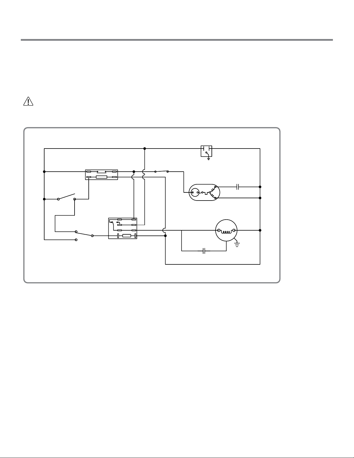
Electrical Requirements
The Santa Fe Compact70 plugs into a common grounded 115VAC outlet. The device draws 5.1 Amps at 80°F and 60%
RH. Locate the dehumidier in an area where the cord’s length (9') easily reaches a 115 VAC electrical outlet with a
minimum of 15 Amp circuit capacity. If used in an area that may become wet, a GFCI protected circuit is recommended.
The unit should not be used in areas prone to flooding. Consult local electrical codes for any further information.
An optional remote dehumidistat is available for use with the Santa Fe Compact70 and is to be located remotely from the
dehumidier.
CAUTION!
ELECTRICAL SHOCK HAZARD: Electrical power must be present to perform some tests. These tests should be
performed by a qualied service person.
Wiring Schematic
BLK-14
DEHUMIDISTAT
ORG-18
BLK-15
FAN SWITCH
BLK-5
BLK-14
1 - AUTO
3 - ON
BLU-17
COMPRESSOR
RELAY
BLU-17
2
GRN-16
BLK-20
WHT-3
FAN RELAY
COIL
N.C.
N.O.
COM
DEFROST
SWITCH
BLK-19
BLK-21
BLK-6
BLK-21
WHT-4
GRN-1
COMPRESSOR
C
BRN-13BLK-8
FAN
CAPACITOR
S
R
YEL-12
RED-11
FAN
COMPRESSOR
CAPACITOR
BLU-10
GRN-7
WHT-2
4032712
Santa Fe Compact70 Installation & Operation Instructions Santa-Fe-Products.com | 800.533.7533
12
Page 13

Warranty
Limited Warranty. Therma-Stor, LLC (“Therma-Stor”) warrants as follows: (i) the Santa Fe Compact70 dehumidifier (“Product”) will be free of material
defects in workmanship or materials for a period of 2 years (“Two-Year Warranty”) following the date of initial purchase of such Product by an original
customer purchasing from Therma-Stor or an authorized reseller (“Customer”); and (ii) the Product’s components will be free of material defects in
workmanship or materials for a period of six (6) years following the date of initial purchase of such Product by a Customer.
Limitation of Remedies. CUSTOMER’S SOLE AND EXCLUSIVE REMEDY UNDER THE ABOVE LIMITED WARRANTY AND THERMA- STOR’S ENTIRE
LIABILITY THEREUNDER, SHALL BE, AT THE SOLE OPTION OF THERMA-STOR, REPLACEMENT OR REPAIR OF SUCH PRODUCT OR ITS COMPONENTS
(“COMPONENTS”) BY THERMA-STOR OR THERMA-STOR’S AGENTS ONLY. REFRIGERANT, PIPING, SUPPLIES, TRANSPORTATION COSTS, LABOR COSTS
INCURRED IN REPAIR OR REPLACEMENT OF SUCH COMPONENTS ARE NOT INCLUDED. THIS DISCLAIMER AND EXCLUSION SHALL APPLY EVEN IF
THE EXPRESS WARRANTY AND LIMITED REMEDY SET FORTH HEREIN FAILS OF ITS ESSENTIAL PURPOSE. CUSTOMER ACKNOWLEDGES THAT NO
REPRESENTATIVE OF THERMA-STOR OR OF ITS AFFILIATES OR RESELLERS IS AUTHORIZED TO MAKE ANY REPRESENTATION OR WARRANTY ON BEHALF
OF THERMA-STOR OR ANY OF ITS AFFILIATES OR RESELLERS THAT IS NOT IN THIS AGREEMENT. Notwithstanding the above, during the term of the TwoYear Warranty only, Therma-Stor will provide, free of charge to Customer, all Components and labor (except costs related to removal and installation of
Product) required to fulfill its obligations under such Two-Year Warranty.
Disclaimer of Warranties. EXCEPT FOR ABOVE LIMITED WARRANTY, WHICH IS THE SOLE AND EXCLUSIVE WARRANTY PROVIDED WITH RESPECT TO THE
PRODUCT AND ITS COMPONENTS, THERMA-STOR HEREBY DISCLAIMS ALL EXPRESS AND IMPLIED WARRANTIES, INCLUDING, WITHOUT LIMITATION, THE
IMPLIED WARRANTIES OF MERCHANTABILITY AND FITNESS FOR A PARTICULAR PURPOSE.
Warranty Limitations. The foregoing limited warranty extends only to a Customer and shall be null and void upon attempted assignment or transfer. A
“defect” under the terms of the limited warranty shall not include problems resulting from Customer’s or Customer’s employees’, agents’, invitees’ or a third
party’s misuse, improper installation, improper design of any system in which the Product is included, abuse, lack of normal care, failure to follow written
instructions, tampering, improper repair, or freezing, corrosion, acts of nature or other causes not arising out of defects in Therma-Stor’s workmanship
or material. If a Product or Component is replaced while under warranty, the applicable limited warranty period shall not be extended beyond the original
warranty time period. The limited warranty does not cover any costs related to changes to a Product or Component that may be required by any codes, laws,
or regulations that may become effective after initial purchase of the Product by Customer.
Customer Responsibilities. As a further condition to obtaining warranty coverage hereunder, the Customer must send a valid warranty claim to ThermaStor such that Therma-Stor receives such claim prior to the end of the applicable warranty period. Therma-Stor shall have no obligation hereunder with
respect to any claim received by Therma-Stor after the expiration of the applicable warranty period. As a further condition to obtaining warranty coverage
hereunder, the Customer must present forms of invoices evidencing proof of purchase of a Product. If such invoices do not clearly indicate the date of initial
purchase by a Customer, the applicable Product’s date of manufacture will be used instead of the date of initial purchase for the purpose of calculating the
commencement of the applicable warranty period. Warranty service must be performed by Therma-Stor or a servicer authorized by Therma-Stor. In order to
obtain warranty service, the Customer should call Therma-Stor at 1-800-533-7533 and ask for the Therma-Stor Products Service Department, which will
then arrange for applicable warranty service. Warranty service will be performed during customary, daytime working hours. If the Product must be shipped
for service, Customer shall be solely responsible for properly packaging the Product, for all freight charges, and for all risk of loss associated with shipment.
Limitation of Liability. IN NO EVENT SHALL THERMA-STOR, IN CONNECTION WITH THE DESIGN, SALE, INSTALLATION, USE, REPAIR, REPLACEMENT OR
PERFORMANCE OF ANY PRODUCT, COMPONENT, PART THEREOF OR WRITTEN MATERIAL PROVIDED THEREWITH, BE LIABLE, TO THE EXTENT ALLOWED
UNDER APPLICABLE LAW, UNDER ANY LEGAL THEORY FOR ANY SPECIAL, DIRECT, INDIRECT, COLLATERAL OR CONSEQUENTIAL DAMAGES OF ANY KIND.
NOTWITHSTANDING THE ABOVE LIMITATIONS AND WARRANTIES, THE SOLE AND EXCLUSIVE LIABILITY OF THERMA-STOR, REGARDLESS OF THE NATURE
OR THEORY OF THE CLAIM, SHALL UNDER NO CIRCUMSTANCES EXCEED THE PURCHASE PRICE OF THE PRODUCT, COMPONENT OR PART UPON WHICH
THE CLAIM IS PREMISED.
Applicable Law and Venue. ANY ARBITRATION, ENFORCEMENT OF AN ARBITRATION OR LITIGATION RELATED TO THE PRODUCT WILL BE BROUGHT
EXCLUSIVELY IN DANE COUNTY, WISCONSIN, AND CUSTOMER CONSENTS TO THE JURISDICTION OF THE FEDERAL AND STATE COURTS LOCATED
THEREIN, SUBMITS TO THE JURISDICTION THEREOF AND WAIVES THE RIGHT TO CHANGE VENUE. CUSTOMER FURTHER CONSENTS TO THE EXERCISE OF
PERSONAL JURISDICTION BY ANY SUCH COURT WITH RESPECT TO ANY SUCH PROCEEDING.
Miscellaneous. If any term or condition of this Limited Warranty is found by a court of competent jurisdiction to be invalid, illegal or otherwise unenforceable,
the same shall not affect the other terms or conditions hereof or thereof or the whole of this Limited Warranty. Any delay or failure by Therma-Stor to
exercise any right or remedy will not constitute a waiver of Therma-Stor to thereafter enforce such rights.
800.533.7533 | Santa-Fe-Products.com Santa Fe Compact70 Installation & Operation Instructions
13
Page 14

Santa Fe Compact70 Installation & Operation Instructions Santa-Fe-Products.com | 800.533.7533
14
Page 15

800.533.7533 | Santa-Fe-Products.com Santa Fe Compact70 Installation & Operation Instructions
15
Page 16

Santa-Fe-Products.com
800.533.7533
 Loading...