

Page 1
OPERATING INSTRUCTIONS
4-CHANNEL RECEIVER
SANSul D1R-8500
SANSUI ELECTRIC COMPANY LIMITED
Page 2
Congratulations on joining the thousands of proud, satisfied owners of quality
stereo components from Sansui.
The QR-6500 is a 280 watt 4-channe1 receiver endowed with practically all
the features necessary for enjoying every type of music in the new, enthralling
4-channe1 form. Incorporating Sansui's exclusive 4-Channe1 Synthesizer
Decoder, it lets you convert today's 2-channe1 stereo records, tapes and FM
multiplex broadcasts into four channels. It lets you reproduce discrete
4-channe1 program sources as well. It also lets you transform 4-channe1 sources
encoded into two channels back to four channels. Needless to say, it lets you
reproduce 2-channe1 sources in 2-channe1 stereo if you so desire.
The QR-6500 connects up to three pairs of speaker systems for the front
channels, and two pairs for the rear channels, enabling you to hear the
reproduction in two rooms. In addition, it is provided with a Synthesizer/
Decoder Function Control and a Mode Switch to let you hear each selection
with the most effective sound effect. In short, we have made it one of the
most complete, most versatile 4-channe1 receivers available today.
Now it is up to you to read the instructions contained in this booklet, so that
you may take full advantage of its rich performance potential.
Again, welcome to the world of 4-channe1 stereo, and our sincere gratitude
for your choice. You will not be disappointed.
CONTENTS
SWITCHES AND CONTROLS .......................................... 3, 4, 5, 6, 7
TO EN,JOY 4-CHANNEL STEREO AT ITS BEST ........................... 8
CONNECTING SPEAKER SYSTEMS/PLAYING RECORDS......... 9, 10
RADIO RECEPTION ............................................................ 11, 12
2-CHANNEL TAPE DECKS ................................................... 13, 14
4-CHANNELTAPEDECK...................................................... 15,16
SIMPLE MAINTENANCE HINTS ................................. 17, 18, 19, 20
ACCESSORIES ........................................................................ 20
SPECIFICATIONS/CHARACTERISTICS................................. 21, 22
Page 3
'm%Ai7»ii*.,
Page 4
SWITCHES AND CONTROLS
1 2 3 4 5 6 7 8 9 1 11 1 1 1 1 1 1 1
PHONES
SPE AK ERS
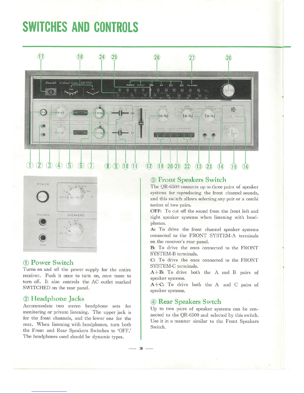
(3) Power Switch
Turns on and off the power supply for tlie entire
receiver. Push it once to turn on, once more to
turn off. It also controls the AC outlet marked
SWITCHED on the rear panel.
(2) Headphone Jacks
Accommodate two stereo headphone sets for
monitoring or private listening. The upper jack is
for the front channels, and the lower one for the
rear. When listening with headphones, turn both
the Front and Rear Speakers Switches to 'OFF.'
The headphones used should be dynamic types.
(3 Front Speakers Switch
The QR-6500 connects up to three pairs of speaker
systems for reproducing the front channel sorinds,
and this switch allows selecting any pair or a combi
nation of two pairs.
OFF: To cut off the sound from the front left and
right speaker systems when listening with head-
phones.
k. To drive the front channel speaker systems
connected to the FRONT SYSTEM-A terminals
on the receiver's rear panel.
B: To drive the ones connected to the FRONT
SYSTEM-B terminals.
C: To drive the ones connected to the FRONT
SYSTEM-C terminals.
A%B: To drive both the
A and B pairs of
speaker systems.
A+C: To drive both the A and C pairs of
speaker systems.
@) Rear Speakers Swtch
Up to two pairs of speaker systems can be con-
nected to the QR-6500 and selected by this switch.
Use it in a manner similar to the Front Speakers
Switch.
3
Page 5
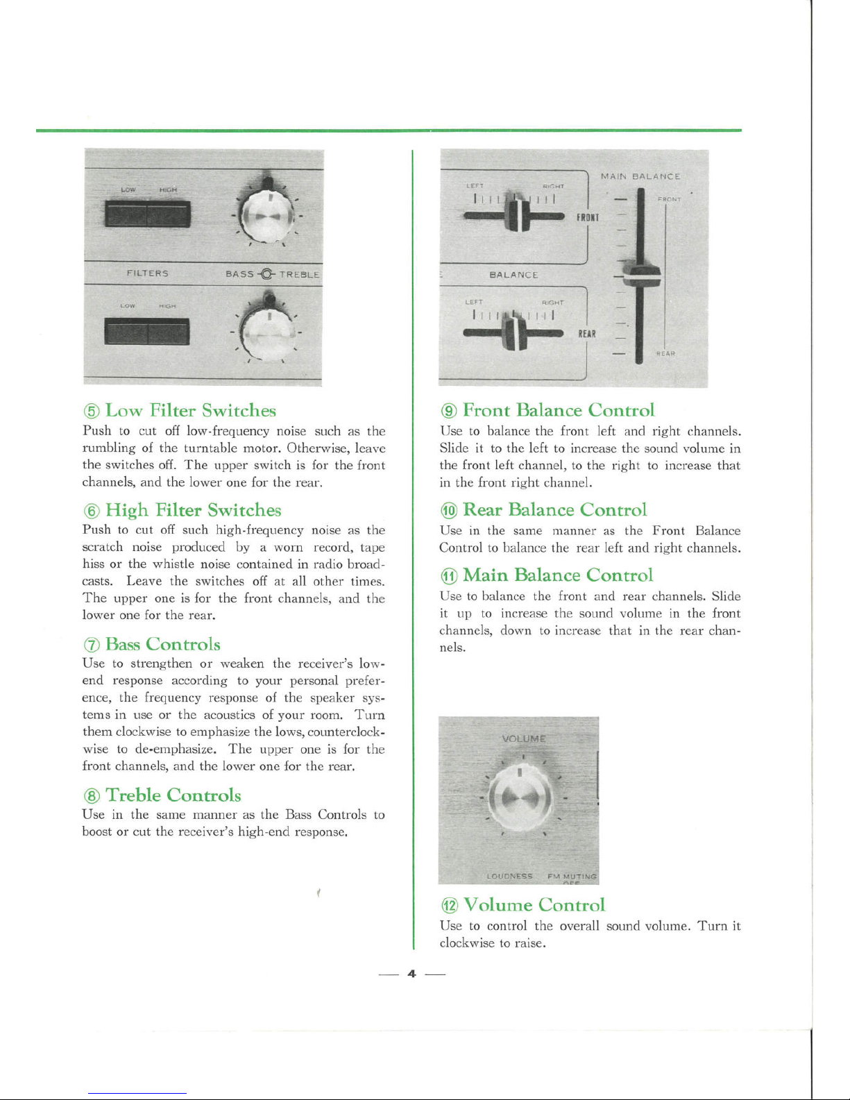
(5 Low Filter Switches
Push to cut off low-frequency noise such as the
rumbling of the turntable motor. Otherwise, leave
the switches off. The ripper switch is for the front
channels, and the lower one for the rear.
@ High Filter Switches
Push to cut off such high-freqriency noise as tl'ie
scratch noise produced by a worn record, tape
hiss or the whistle noise contained in radio broad-
casts. Leave the switches off at all other times.
The upper one is for the front channels, and the
lower one for the rear.
(7
Bass Controls
Use to strengthen or weaken the receiver's low-
end response according to your personal prefer-
ence, the frequency response of the speaker sys-
tems in use or the acoustics of your room. Turn
them clockwise to emphasize the lows, counterclock-
wise to de-emphasize. The ripper one is for the
front channels, and the lower one for the rear.
(8 Treble Controls
Use in the same manner as the Bass Controls to
boost or cut the receiver's high-end response.
(9 Front Balance Control
Use to balance the front left and right channels.
Slide it to the left to increase the sorind vofüme in
the front left channel, to the right to increase that
in the front right channel.
@ Rear Balance Control
Use in the same manner as the Front Balance
Control to balance the rear left and right channels.
@ Main Balance Control
Use to balance the front and rear channels. Slide
it rip to increase the sorind volume in the front
channels, down to increase that in the rear chan-
nels.
@ Volume Control
Use to control the overall sound volume. Turn it
clockwise to raise.
4
Page 6
SWITCHES AND CONTROLS
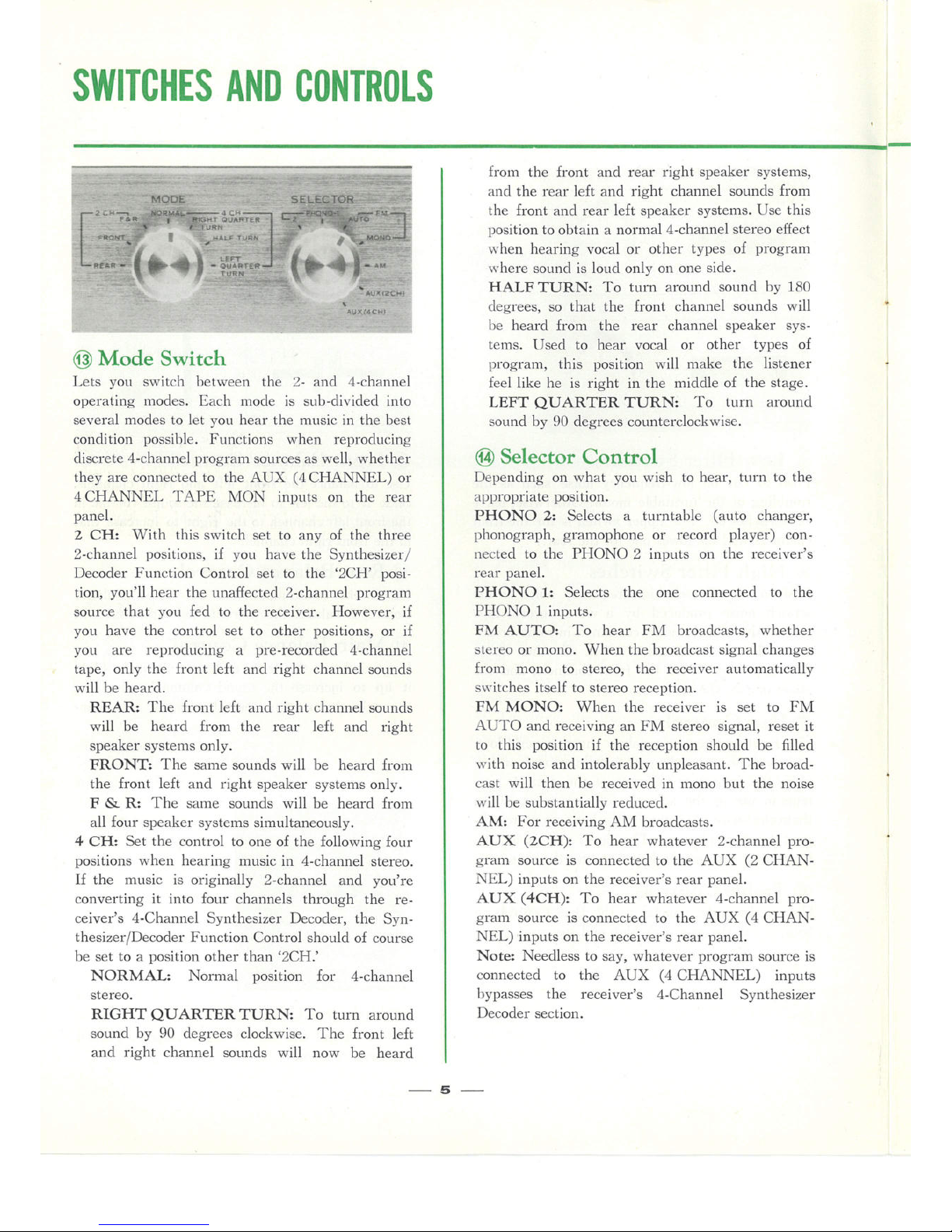
@ Mode Switch
Lets yori switch between the 2- and 4-channe1
operating modes. Each mode is sub-divided into
several modes to let yori hear the music in the best
condition possil:ile. Functions when reproducing
discrete 4-channe1 program sources as well, whether
they are connected to the AUX (4 CHANNEL) o.i-
4 CHANNEL TAPE MON inprits on the rear
panel.
2 CH: With tliis switch set to any of the three
2-channe1 positions, if you have the Synthesizer/
Decoder Function Control set to the '2CH' posi-
tion, you'll hear the rinaffected 2-channe1 program
sorirce that yori fed to the receiver. However, if
you have the control set to other positions, or if
yori are reproducing a pre-recorded 4-channe1
tape, only the front left and right channel sounds
will be heard.
REAR: The front left and right channel sounds
will be heard from the rear left and right
speaker systems only.
FRONT: The same sounds will be heard from
the front left and right speaker systems only.
F & R: The same sounds will be heard from
all four speaker systems simultaneously.
4 CH: Set the control to one of the following four
positions when hearing music in 4-channe1 stereo.
If the n"irisic is originally 2-channe1 and you're
converting it into four channels through the re-
ceiver's 4-Channe1 Synthesizer Decoder, the Syn-
thesizer/Decoder Function Control should of course
be set to a position other than '2CH.'
NORMAL: Normal position for 4-channe1
stereo.
RIGHT QUARTER TURN: To turn around
sound by 90 degrees clockwise. The front left
and right channel sounds will now be heard
from the front and rear right speaker systems,
and the rear left and right channel sounds from
the front and rear left speaker systems. Use this
position to obtain a normal 4-channe1 stereo effect
when hearing vocal or other types of program
where sorind is loud only on one side.
HALF TURN: To turn around sorind by 180
degrees, so that the front channel sounds will
l:ie heard from the rear channel speaker sys-
tems. Used to hear vocal or other types of
program, this position will make the listener
feel like he is right in the middle of the stage.
LEFT QLiARTER TURN: To turn arorind
sound by 90 degrees corinterclockwise.
@ Selector Control
Depending on what you wish to hear, fürn to the
appropriate position.
PHONO 2: Selects a turntable (arito changer,
pl"ionograph, gramophone or record player) con-
nected to the PHONO 2 inprits on the receiver's
rear panel.
PHONO 1: Selects the one connected to the
PHONO 1 inprits.
FM AUTO: To hear FM broadcasts, whether
stereo or mono. When the broadcast signal changes
froin mono to stereo, the receiver automatically
switches itself to stereo reception.
FM MONO: When the receiver is set to FM
AUTO and receiving an FM stereo signal, reset it
to this position if the reception should be filled
with noise and intolerably rinpleasant. The broad-
cast will then be receiyed in mono but the noise
will be substantially reduced.
AM: For receiving AM broadcasts.
AUX (2CH): To hear whatever 2-channe1 pro-
gram source is connected to the AUX (2 CHAN-
NEL) inputs on the receiver's rear panel.
AUX (4CH): To hear whatever 4-channe1 program source is connected to the AUX (4 CHAN-
NEL) inputs on the receiver's rear panel.
Note: Needless to say, whatever program source is
connected to the AUX (4 CHANNEL) inputs
bypasses the receiver's 4-Channe1 Synthesizer
Decoder section.
s
Page 7
For this sound effect, the '2-2 System' of speaker
positioning is more effective.
il.Ill%%,,_,.fö,,:-. ':# - -;:,_;E..-.. - :XZ ." :;!,
'oN"o"Äo"""'.f4.:' l
5!
;'X-a' J3i
Q
'!
fö @
l
I-';f_.%
p_a.y,.q,Ä-j7:,;
;&;f="'=-
)Ä_;I:_l:.:' 7tl _ . :. 'ai.. . . _ _ ,I::l:. lJ Tr:H. 'x_., .. ..
i:ffl%iiiitq:p4:gffi
':" " '= s'uq;'Ö9sb7bt6offin :
- föNCERt=l ..-. ... - -. ..
r -- - - .. .
o:" o"qs
(.ONCiRT " ::Ö :;.' ":
'X:
'Ä::,7/ ': '.'='
t:Ql . , ,.-, . ,
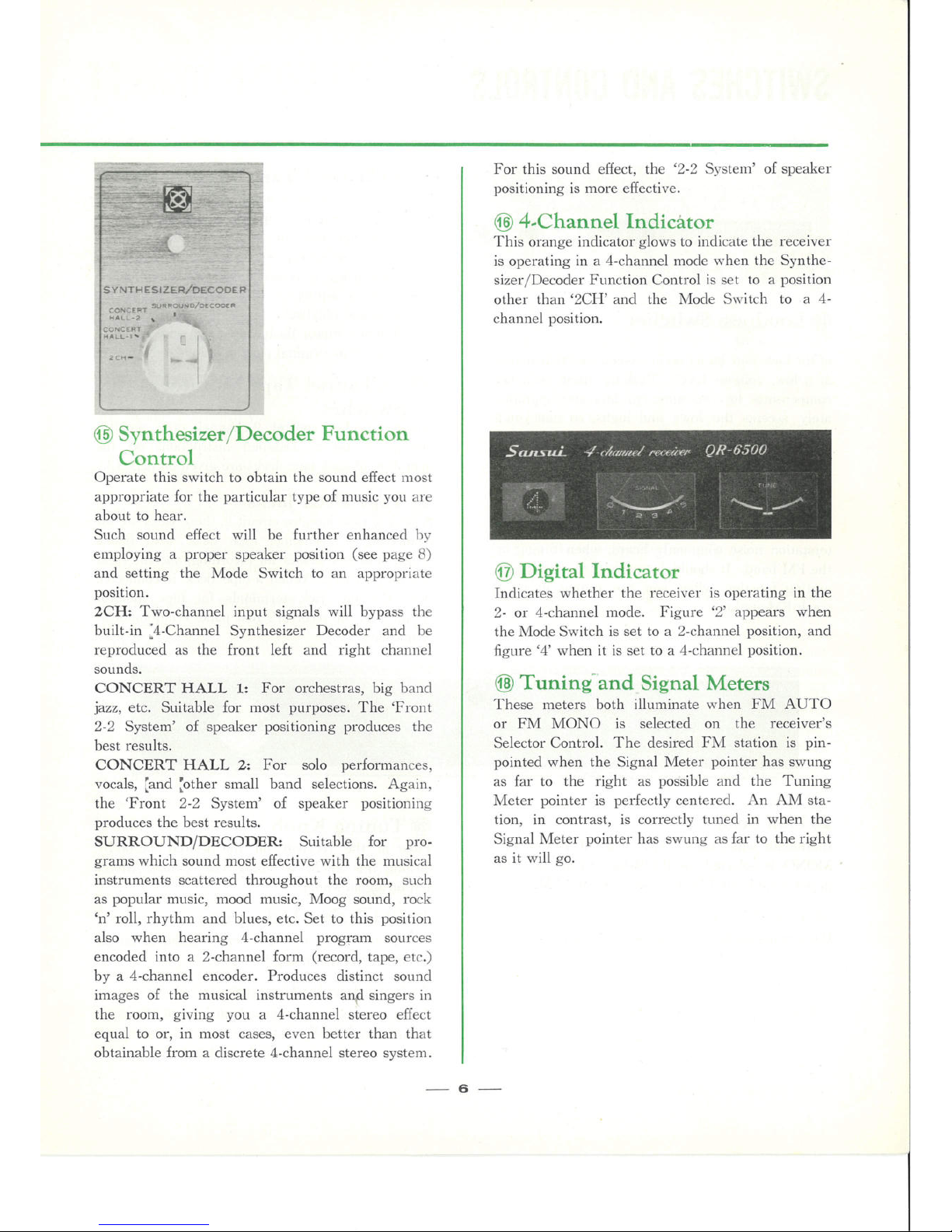
@) 4-Channe1 Indicätor
This orange indicator glows to indicate the receiver
is operating in a 4-channe1 mode when the Synthe-
sizer/Decoder Function Control is set to a position
other than '2CH' and the Mode Switfö to a 4-
channel position.
@ Synthesizer/Decoder Function
Control
Operate this switch to obtain the sound effect most
appropriate for the particular type of tnusic yohi are
about to hear.
Such sound effect will be further enhanced by
employing a proper speaker position (see page 8)
and setting the Mode Switch to an appropriate
position.
2CH: Two-channel input signals will bypass tl"ie
built-in o,4-Channe1 Synthesizer Decoder and be
reproduced as the front left and right channel
sounds.
CONCERT HALL 1: For orchestras, big band
jazz, etc. Suitable for most purposes. The 'Front
2-2 System' of speaker positioning produces the
best results.
CONCERT HALL 2: For solo performances,
vocals, ,'and ',other small band selections. Again,
the 'Front 2-2 System' of speaker positioning
produces the best results.
8URROUND/DECODER: Suitable for pro-
grams which sound most effective with the musical
instruments scattered throughout the room, such
as popular music, mood rnusic, Moog sound, rock
'n' roll, rhythm and blues, etc. Set to this position
also when hearing 4-channe1 program sorirces
encoded into a 2-channe1 form (record, tape, etc.)
by a 4-channe1 encoder. Produces distinct sound
images of the musical instruments an,d singers in
the room, giving you a 4-channe1 stereo effect
equal to or, in most cases, even better than that
obtainable from a discrete 4-channe1 stereo system.
@ Digital Indicator
Indicates whether the receiver is operating in the
2- or 4-channe1 mode. Figure '2' appears when
the Mode Switch is set to a 2-channe1 position, and
figure '4' when it is set to a 4-channe1 position.
@
Tuning-and Signal Meters
These meters both ilfüminate when FM AUTO
or FM MONO is selected on the receiver's
Selector Control. The desired FM station is pin-
pointed when the Signal Meter pointer has swung
as far to the right as possible and the Tuning
Meter pointer is perfectly centered. An AM sta-
tion, in contrast, is correctly tuned in when the
Signal Meter pointer has swung as far to the right
as it will go.
6
Page 8
SWflCHES AND CONTROLS
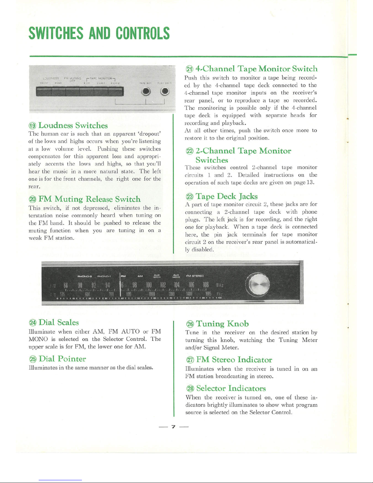
@ Loudness Switches
The füunan ear is such that an apparent 'droporit'
of the lows and highs occurs when you're listening
at a low vofüme level. Pushing these switches
con'ipensates for this apparent loss and appropri-
ately accents the lows and highs, so that yori'll
hear the nuisic in a more nafüral state. The left
one is for the front channels, the right one for the
rear.
(O FM 'Muting Release Switch
This switch, if not depressed, eliminates the in-
terstation noise commonly heard when füning on
the FM band. It should be pushed to release the
muting function when you are tuning in on a
weak FM station.
@ 4-Channe1 Tape Monitor Switch
Push this switch to monitor a tape being record-
ed by the 4-channe1 tape deck connected to the
4-channe1 tape monitor inprits on the receiver's
rear panel, or to reproduce a tape so recorded.
Tlie monitoring is possible only if the 4-channe1
tape deck is equipped with separate heads for
recording and playback.
At all other times, prish the switch once more to
restore it to the original position.
@ 2-Channe1 Tape 'Monitor
Switches
Tl"iese switches control 2-channe1 tape monitor
circuits 1 and 2. Detailed instructions on the
operation of such tape decks are given O1] page 13.
@ Tape Deck Jacks
A part of tape monitor circuit 2, these jacks are for
connecting a 2-channe1 tape deck with phone
pfügs. The left jack is for recording, and the right
one for playback. When a tape deck is connected
here, the pin jack terminals for tape monitor
circuit 2 on the receiver's rear panel is automatical-
ly disabled.
@ Dial Scales
Illuminate when either AM, FM AUTO or FM
MONO is selected on the Selector Control. The
upper scale is for FM, the lower one for AM.
@ Dial Pointer
Illuminates in the same manner as the dial scales.
@ Tuning Knob
Tune in the receiver on the desired station by
turning this knob, watching the Tuning Meter
and/or Signal Meter. '
@ FM Stereo Indicator
Illuminates when the receiver is tuned in on an
FM station broadcasting in stereo.
@ Selector Indicators
When the receiver is turned on, one of these in-
dicators brightly illuminates to show what program
source is selected on the Selector Control.
7
Page 9

TO ENjOY 4-CHANNEL STEREO AT ITS BEST
The 4-channe1 stereo systein far excels the conven-
tional 2-channe1 system in its capability to faithfully
reproduce the sound field normally present in any
live performance. Yorir QR-6500 incorporates a QS
synthesizing/decoding matrix to re-organize ordinary
2-channe1 stereo signals to four channels and estab-
lish distinct sound images of the musical instrru'nents
and singers, as well as Sansui's excfüsive phase
modulator circuit to lend the reproduced sound the
liveliness or presence of the original sound field.
The end effect of such treatment is so exciting and
enthralling that many aridio experts the world over
have termed it prirely revolutionary. It is particu-
larly oritstanding when yori feed to the receiver 4-
channel programs encoded into a 2-channe1 form l»y
a 4-channe1 encoder.
So that yori may enjoy 4-channe1 stereo music at its
best, it is of course important that yori know all
about the switches and controls of the receiver and
put them to full rise. &it a few other useful hints
are certain to help you hear the music more efiective-
ly, and will be outlined below.
[-FRONTg-
H;H;HqH
<"k REAR A
'%' SPEAKER
SYSTEMS "
/
Speaker System Positions
The positions of the forir speaker systems in a 4-
channel stereo system is an essential consideration
if you are to enjoy 4-channe1 stereo sound at its best.
It is essential that you place them appropriately to
suit the type of program sorirce yori wish to hear.
Two basic positions will be explained below, but
you are free to adapt them to the particular condi-
tions-both acoustic and I:ihysical-of your room
for optimum 4-channe1 stereo effects.
1) 2,2 System
This is the 4-corner position widely accepted as the
'standard' for 4-channe1 stereo. While it is particu-
larly good for hearing
f- FRONT (-
SPEAKER -'-'
SYSTEMS
-%
.,l
/-» REAR ä
' SPEAKER &V;]
' SYSTEMS "-'/
program sorirces enco-
ded by a 4-channe1
encoder, it is also effec-
tive for these types of
program sorirce: mood
music, popular music,
contemporary music,
Moog sound, rhythm
and blues, musicals,
and live recordings.
2) Front 2,2 System
This system moves the rear speaker systems rip
front as shown below and creates a sound field-the
equivalent of a concert '
hall stage -in front of
you. It is suitable for
those types of program
source which more or
less require an objective
attifüde Of the aridience,
such as: symphonies,
operas, chamber music,
modern jazz and big
band jazz.
3) Others
Variations of the above two systems are possible,
and you are absolutely free to devise one to suit the
particular conditions of your room.
If the Program Source is
Monophonic
The QS synthesizing/decoding matrix incorporated
in the QR-6500, by principle, is unable to produce
a 4-channe1 stereo effect from a monophonic pro-
gram source. When yori listen to such monophonic
program sources as AM broadcasts, FM mono
broadcasts and mono records, it is usually advisable
to set the Synthesizer/Decoder Function Control to
'2CH' and hear them in mono, bypassing the matrix.
Some mono sorirces, however, acqriire depth when
processed through that matrix, so it may be worth
your while to experiment for yourself.
8
Page 10

CONNECTING SPEAKER SYSTEMS/PLAYING RECORDS
Connecting Speaker Systems
The QR-6500 connects rip to three pairs of speaker
systems for the front channels, and two pairs for
the rear. Any pair may be driven independently
or a combination of two pairs may be driven, as
selected by the Front and Rear Speakers Switches.
Connect them to the receiver as instructed in the
diagram on the next page, taking care not to confuse
tl'ie front and rear, left and right channels, and föe
pfüs and mimis polarities. Sufficient care shorild be
taken not to short-circuit the pfüs and mimis leads.
As the connecting terininals all adopt Sansui's
riniqrie one-torich design, connections can 1»e made
simply by pushing the button, inserting the lead
wires of the speaker cord, then releasing the button.
About the Speaker Impedance
Each speaker system connected to yorir QR-6500
must possess an impedance of from 4 to 16 ohms.
Should you wish to drive two pairs of sl:ieaker sys-
tems simultaneously, they should all have an im-
pedance of 8 ohms or more.
About the Speaker Polarities
Whether or not the four speaker systems in a 4-
channel stereo system are in phase with one another
is an important factor to the maximum enjoyment
of 4-channe1 stereo sound. The phase relationship
must be correct not only between the front left and
right speaker systems, and the rear left and right
speaker systems, but also between the front channels and rear channels.
When connecting each speaker system to the receiver, be certain to keep the plus and minus polari-
ties in the correct order at both ends.
Front & Rear Speakers Switches
If you have two pairs of speaker systems available
for use as the rear channel speaker systems, you
could place one pair to form the '2-2 System' and
the other pair to form the 'Front 2-2 System' of
speaker positioning. Then you could operate the
Rear Speakers Switch to select either system to suit
the particular type of music being reproduced. Or,
you could install four speaker systems in two rooms
and enjoy 4-channe1 stereo music in either room independently or both rooms simultaneously by the
use of the Front and Rear Speakers Switches.
Choice of the Turntable
The turntable connected to the QR-6500 shorild be
eqriipped with a magnetic cartridge with an oritprit
voltage of from 2 to lOinV. The cartridge should
be inspected beforehand as to whether the left and
right cliannels are perfectly in phase or the left and
right channel output voltages are proportionate, or
the 4-channe1 stereo effect could be seriously im-
paired. Attention should be also paid to whether
tl'ie styfüs is worn orit, whether dust is sfück on it
or whether the styfüs pressure is appropriate or not.
Connecting Turntables
As the QR-6500 is equipped with two phono input
circuits, it is possible to eml:iloy two turntables or
two tonearms.
Connections shorild be made with shielded cables,
taking care not to confuse the left and right channels.
Playing Records
1. Set the receiver's Selector Control to 'PHONO 1'
or 'PHONO 2' depending on which inprit circuit
70tl are tlSing.
2. Turn on the turntable, and adjust it for the right
speed.
3 , Start playing the record.
4 . Set the receiver's Mode Switch to an appropriate
position, depending on the type of music being re-
produced.
5. Adjust the receiver for optimum sound volume
as well as for optimum balance between the front
and rear, left and right channels.
6, Operate the receiver's Synthesizer/Decoder
Function Control to obtain the desired sound effect.
7. Use the tone controls and other switches and
controls according to your personal preference or
the room acoustics.
e
Page 11

CONNECT THE OUTPUTS
OF AN AUXILIARY
COMPONENT
TURNT ABLE (2)
REAR SPEAKER
SYSTEMS (B)
RIGHT LEFT
TURNT ABLE (1)
REAR SPEAKER
SYSTEMS (A)
Power Cord
The power cord for the QR-6500 is included in
the polyethylene bag with the other accessories
provided with the receiver.
Insert the connector end of it into 'AC LINE IN-
PUT' socket on the receiver's rear panel.
RIGHT
LEFT
WALL AC OUTLET
RIGHT
FRONT SPEAKER
SY3TEMS (A)
LEFT
10
Page 12

RADIO RECEPTION
Connecting Antennas
The wonderful 4-channe1 stereo effect would be
seriously impaired if considerable noise is mixed
with the radio broadcast received by the QR-6500.
As the qriality of the reception is largely dependent
ripon the antennas, be sure to connect them correctly and enjoy noise-free broadcasts.
FM Antennas
T,8haped Feeder Antenna
If you live in the proximity of broadcast stations
where radio waves are able to travel unobstructed,
quality reception can be usually achieved by setting
up the T-shaped feeder cable antenna supplied with
the receiver as illustrated on the next page, connecting it to the receiver's FM 300Ü terminals. Set rip
the receiver for FM reception and stretch the antenna
to a full T shape, change its height and direction
rintil the best reception is obtained.
External FM Antenna
Il] areas remote from broadcast stations or blocked
by such obstacles as mountains and large buildings,
the above-mentioned feeder antenna alone may fail
to give you quality reception of FM stations. The
problem, however, can be risually overcome by installing an external FM antenna.
While n"iany different types of antenna are com-
mercially available, we recommend to use one with
at least 5 or 7 elements. The antenna is normally
connected to the same FM 300fl terminals by means
of feeder cable, but such cable should be kept as
short as possible lest it should pick up noise. Change
the height, direction and position of the antenna
rintil you are certain yori're receiving the broadcast
with the best sensitivity.
If you should need long feeder cable to connect the
antenna or where the automobile traffic is heavy, it
is advisable to employ 7EM2 coaxial cable. In this
case, however, it is necessary to connect a matching
transformer between the antenna and the coaxial
cable to match their impedances. The cable should
be connected to the FM 75Ü terminals. (If the an-
tenna itself has an impedance of 75D!, no matching
transformer is needed.)
AM Antenna
The highly sensitive AM ferrite bar antenna, pro-
vided on the back of the receiver, is usually suf-
ficient to obtain quality reception of AM stations.
To use, sin'iply pull it out as ilfüstrated.
Should the bar antenna fail to give you clear recep-
tion, however, connect a piece of polyvinyl wire
supplied to the AM-A terminal on the receiver's
rear panel and stretch it outside a window or on the
roof. Still better results would be obtained if yori
grorind the receiver.
Radio Reception
FM Broadcasts
1. Set the Selector Control to 'FM AUTO.'
2. Select the desired FM station by turning the
Tuning Knob. It is correctly pinpointed when the
Signal Meter pointer has swung as far to the right as
possible and the Tuning Meter pointer is accurately
centered. If the station received is broadcasting in
stereo, the Stereo Indicator will ilfüminate.
3. If disfürbing noise interferes with the reception,
reset the Selector Control to 'FM MONO ' and the
station wiill be received monophonically and the noise
will be drastically cut down.
4. Operate the various other controls and switches
to obtain the best 4-channe1 stereo effect.
AM Broadcasts
1. Set the Selector Control to 'AM.'
2. Choose the desired station by fürning the Tuning
Knob rintil the Signal Meter pointer swings as far
to the right as it will go near the frequency of that
station. The Tuning Meter does not light when the
receiver is set to receive AM broadcasts.
3. Use the various other controls and switches to
suit your personal preference or the room acoustics.
Note: When receiving FM mono or AM broadcasts,
it is better to leave the Synthesizer/Decoder
Function Control at '2CH' and let the signals bypass
the receiver's built-in 4-Channe1 Synthesizer Decoder.
11
Page 13

12
EXTERNAL FM ANTENNA (30(fü)
EXTERNAL FM ANTENNA (75ü) EXTERNAL AM ANTENNA
300n BALANCED
FEEDER WIRE
T-SHAPED FEEDER ANTENNA
3üOn BALANCE0
FEEDER WIRE
MATCHING
TRANSFORMER
75(1 UNBALANCE[)
COAXIAL CABLE
FM LOCAL,/DISTANT
ANTENNA SWITCH
PVC WIRE
GROUNDING
COPPER PLATE
B U R I E D U N DER G RO U N D
Page 14

2-CHANNEL TAPE DECKS
Recording and Playback on
2-Channe1 Tape Decks
If you couple a 2-channe1 tape deck to the QR-6500,
you'll be able to record and playback a 2-channe1
stereo tape. Of course, the playback sound can be
converted, if dasired, into four channels 1»y the 4-
Channel Synthesizer Iacoder and reproduced out of
the four speaker systems. If the tape deck is of a
3-head type (with separate record and play heads),
Y)70L1'11 be able to monitor the sound as it is recorded.
fö addition,
if you connect two tape decks to the
QR-6500, you'll be able to record into both of them
simultaneously or copy a recorded tape from one to
the other.
Connecting 2-Channe1 Tape Decks
The QR-6500 is provided with two 2-channe1 tape
monitor circuits; on= has pin jack terminals and a
DIN cünnector socket, while the other has pin jack
terminals afü phona type jacks. If you are connect-
ing only ona tapa deck, you are absolutely free to
use any terminals that are most convenient. But if
you are connecting two tape decks, be sure to con-
nect one of them to either terminals of the first tape
monitor circuit, and the other to either terminals of
the second tape monitor circuit. If a tape deck is
connected to the phone type jacks of the second tape
monitor circuit, the pin jack terminals are automatically cut off and cease to function.
If Using Pin Jacks
If you are using the pin jack terminals to connect
your tape deck, proceed as follows:
1. Connect a pair of shielded cables between the
'TAPE REC 1 (or 2)' pin jack terminals of the QR-
6500 and the recording input terminals of your tape
deck.
2. Connect another pair of such cables between the
receiver's 'TAPE MON 1 (or 2)' pin jack terminals
and the tape deck's playback (or monitor) output
terminals. Be sure to keep the left and right chan-
nel cables in the correct order at both ends.
If 'Using the DIN Socket
If your tape deck is eqriipped only with a DIN COII-
nector socket, plug the DIN connector cable extend-
ing from it into the 5-pin DIN connector socket
(marked 2 CHANNEL RECORDER 1) on the receiver's rear panel.
If Using Phone Jacks
Should your tape deck be equipped with cables with
phone type plugs, connect them to the phone jacks
on the receiver's front panel. The tape deck's re-
cording input plug should be inserted into the 'TAPE
REC' jack on the left, and its playback oritput
plug into the 'PLAYBACK' jack on the right.
2-Channe1 Recording & Playback
Procedures
To Record into a 2,Channe! Tape Dack
1. Set the receiver's Selector Control to the pro-
gram source you want to record.
2 '. Start the tape deck in the recording mode.
3 . To monitor the sound being recorded, push the
'2CH-1' or '2CH-2' tape monitor switch on the re-
ceiver's front panel, depending on which of the two
2-channe1 tape monitor circuits is accommodating
the tape deck at the moment.
To Reproduce the Recorded Tape
1. If you have connected the tape deck to the first
2-channe1 tape monitor circuit, push the '2CH-1'
tape monitor switch on the receiver's front panel.
If you've connected it to the second circuit, prish the
'2CH-2' tape monitor switch.
2. Start the tape deck in the playback mode.
3. Use the various controls and switches on the re-
ceiver to obtain the best 4-channe1 stereo effect.
Recording into Two 2,Channe1 Tape
Decks Simultaneously
1. Set the receiver's Selector Control to the program source you want to record.
2. Start both tape decks in the recording mode.
-13
Page 15

Recording from One Tape Deck to
the Other
1. Push the '2CH-1' tape monitor switch of the re-
CelVel.
2. Start the tape deck connected to the second tape
monitor circuit, in the recording mode.
3. Now start the other tape deck (connected to the
first tape monitor circuit) in the playback mode.
Note:
1. If the tape deck referred to in step 2 is of a
3-head type, the tape being copied can be monitored
simply by pushing the '2CH-2' tape monitor switch
of the receiver.
2. The copying (dubbing) of a recorded tape, as
described above, is only possible from a tape deck
connected to the first tape monitor circuit to the one
connected to the second tape monitor circuit.
2-CH. TAPE DECK (1)
2-CH. TAPE DECK (2)
= LEFT CHANNEL
- RIGHT CHANNEL
14
Page 16

4-CHANNEL TAPE DECK
Recording and Playback on a
4-Channe1 Tape Deck
If you connect a 4-channe1 tape deck to the QR-
6500, you'll be able to record and reproduce a 4-
channel stereo tape. You may either recordt the
4-channe1 stereo sound converted from 2-channe1
program sources by the receiver's built-in 4-Chan-
nel Synthesizer Decoder, or if you connect two 4-
channel tape decks, you'll even be able to record
froin a discrete 4-channe1 stereo tape. Of course, if
the tape deck is of a 3-head type, it is possible to
monitor the sound being recorded.
Connecting a 4,Channe1 Tape Deck
You may either connect a 4-channe1 tape deck to
the receiver's 4-channe1 tape monitor pin jacks or
DIN connector sockets. If using the former:
1. Connect the tape deck's recording input ter-
minals with the receiver's 4-channe1 TAPE REC
pin jacks, using shielded cables with pin plugs, and,
2. Connect the tape deck's playback output ter-
minals with the receiver's 4-channe1 TAPE MON
pin jacks, using similar cables. In both cases, be sure
that the front and rear, left and right channel cables
are kept in the correct order at both ends.
Note: On may tape decks, each of the four chan-
nels is designated as follows :
Front left .....................Channel 1 or Track 1
Front right.....................Channel 3 or Track 3
Rear left........................Channel 2 or Track 2
Rear right .....................Channel 4 or Track 4
A 4-channe1 tape deck can also be connected to the
receiver's DIN connector sockets. The QR-6500 is
provided with two such sockets on the rear panel -
the upper one for the front channels and the lower
one for the rear channels. To connect, you only
need plug the DIN connector cables of the tape deck
into the appropriate sockets firmly, taking care not
to confuse the front and rear channels.
4,Channe1 Recording Procedures
To record the 4-channe1 sorind converted from 2-
channel program sources by the receiver's built-in
4-Channe1 Synthesizer Decoder, follow tlie simple
steps described below.
1. Set the receiver's Selector Control to the pro-
gram source you wish to record. However, if the
program source is a 2-channe1 stereo tape, operate
both the 2-channe1 tape deck and the receiver to
reproduce the tape, in accordance with the instruc-
tions on '2-Channe1 Recording & Playback Procedures' on page 13.
2. Turn the receiver's Synthesizer/Decoder Func-
tion Control to a position that gives you the sorind
effect best suited to the type of music yori are about
to record.
3. Adjust the receiver's Volume Control so as to
feed signals of appropriate strength into tlie tape
deck.
4. Start the 4-channe1 tape deck in the recording
mode.
NOTE: Push the '4CH' tape monitor switch on the
receiver's front panel if you want to monitor the
recording as you make it.
If you want to copy a 4-channe1 stereo tape, you
need another 4-channe1 tape deck. This second
tape deck shorild be connected to the receiver's 4channel A{JX input terminals, using shielded cables
with pin plugs.
Then:
1. Set the receiver's Selector Control to 'AUX
(4CH).'
2. Start the first 4-channe1 tape deck (connected to
the 4-channe1 tape monitor terminals) in the recording mode.
3, Start the other 4-channe1 tape deck (connected
to the 4-channe1 A{JX input terminals) in the play-
back mode to reproduce the 4-channe1 stereo tape.
15
Page 17

4-Channe1 Playback Procedure
1. Push the '4CH' tape monitor switch on the
receiver's front panel.
2. Start the 4-füanne1 tape deck in tlie playl»ack
mode.
3. Use tlie various controls and switches on the
receiver to obtain the best 4-föanne1 stereo effect.
I
I
I
'l
e a@o
Q
I
I aaaaai I
'l
I
I I,_alN_ff-l-ill
I
llffi F ffl_li_l§ßJ ,l
4-CH. TAPE DECK
-4-CH. TAPE DtCK '
(With DIN Connector Sockets)
-16 --
Page 18

SIMPLE MAINTENANCE HINTS
Rear-Panel AC Outlets
Of the three AC outlets provided on the rear panel,
the one marked 'SWITCHED' is controlled by the
front-panel Power Switch. The other two, marked
'UNSWITCHED,' are always 'live' and independent
of the Power Switch. AIl three outlets have limited
power capacities, and it is extremely dangerous to
connect equipment with bigger power requirements.
Before connecting any equipment, make certain its
power requirement does not exceed the power capacity limit.
FM Local/Distant Antenna Switch
Should you happen to live near a broadcasting
station, the FM radio wave may be excessively
strong, distorting the sound. In such a case, change
this switch to 'LOC,' and the distortion will nor-
mally disappear and you'll have a pleasant recep-
tion. Leave the switch at 'DIST' at all other times.
PM Connectors
These are the U-shaped jumper connectors connect-
ing the 'PRE OUT' (preamplifier output) terminals
and the 'MAIN IN' (power amplifier input) ter-
minals on the receiver's rear panel, and can be very
easily pulled out. With these connectors unplugged,
the four preamplifiers and the four power amplifiers
of the QR-6500 are separated and may be inde-
pendently used. For example, other preamplifiers
may be connected to the 'MAIN IN' terminals, or
other power amplifiers to the 'PRE OUT' terminals.
This would make it possible to upgrade your 4-
channel stereo system further by adopting the 'elec-
tronic crossover system,' among other things.
NOTE:
1, Be sure to leave the PM connectors firmly plug-
ged in unless you connect other preamplifiers or
power amplifiers. -yT'a" ,..,,,
2. Cut off the . .
Power Switch
without failure o "l
before you plug
in or out the PM
connectors.
ELECTRONIC CROSSOVER SYSTEM
POWER
AMP.
ELECTRONIC TWEETER
CROSSOVER 'DIVIDER
POWER
AMP.
PRE MAIN MIDRANGE
OUT IN
PROGRAM
SOURCES o"-6500
WOOFER
17
Page 19

About the Place of Installation
Tlie wooden cabinet of tl'ie QR-6500 is designed so
that any heat radiated inside wil] effectively escape
through it. Proper care should tlierefore be taken
of the dissipation of such lieat if you wish to place
sometliing on top of tlie receiver or place it inside
a closed box, etc. Above all, avoid placing it where
it n'iay be exposed to the direct sunlight.
Hum and Howling
Care must be taken never to place a turntable on or
too near a speaker system, or the vibration of the
speaker system is transmitted and carises howling.
It is best to keep these components completely
separated, but if this is impossfüle, place a thick
cushion between them.
Humming is a phenomenon caused by incomplete
or incorrect turntable-receiver connections. Should
this occur check to see if all connections are com-
pletely n'iade and if the connecting wires are suf-
ficiently thick.
When Connecting a Turntable, etc.
To connect a turntable, tape deck and so forth, it is
strongly recommended to use thick, shielded cables
with a minimum of distributed capacity and to keep
them as short as possible.
To solder the pin plugs supplied as acccessories onto
such sliielded cables, refer to the illustration below.
CONNECTING SHIELDED CABLE TO A PIN PLUG
(D REMOVE PIN PLUG COVEß PIN PLUG
INSERT
(2 SOLDER
PIN J 'C
CUT OFF EXCESS ffl REPLACE COVER
ANDSOLDER ri T!ll
Grounding
Any noise picked up by the connecting cables can be
effectively grounded by connecting a piece of PVC
(polyvinyl chloride) or enameled wire to the 'GND'
terminal on the QR-6500's rear panel, attaching a
small copper plate or carbon rod to the other end
and burying it deep underground. The grounding
leads of other equipment in your 4-channe1 stereo
system s'nay be connected to the same terminal to
ground the entire system at once.
If yori have connected an external AM antenna to
the receiver, it is advisable to ground it at the same
time.
f
18
Page 20

SIMPLE MAINTENANCE HINTS/ACCESSORIES
Should the Power Fuse BIow
If no Selector Indicator should glow and the receiver
simply remains dead even after you have turned on
its Power Switch, it is possible that its power fuse
has blown. If this happens, disconnect the power
cord from the wall AC outlet at once and examine
the power fuse on the receiver's rear panel. If you
find it blown, replace it with a new glass-tubed fuse
of the rated capacity (5-ampere for 100 to 127 volts,
3-ampere for 220 to 250 volts). Never use a fuse of
a different capacity or a piece of wire, even as a
stop-gap measure, or serious danger could result.
About the Quick-Acting Fuses
When a Selector Indicator is glowing, if no sound
comes out of one or more of the forir speaker systems,
examine their connections and operation once. If
nothing is wrong with them, it is possible that tlie
quick-acting füse or fuses protecting the power
transistors have blown.
If this should happen, disconnect the power cord
from the wall AC outlet immediately and check the
four quick-acting fuses on the rear panel. If you
find any of them blown, discover and eliminate the
cause of the blowout, and replace it with a new 3-
ampere quick-acting fuse supplied. Probable causes
of the blowout infüföe excessively large input signals
and a short-circuit at the speaker terminals.
19
Page 21

Voltage Adjustment
So that you may operate yorir QR-6500 in any part
of the world, it is equipped with Voltage Selector
Pfügs. As it is set to the correct power supply
voltage of your area in oru- factory prior to ship-
ment, there is no need to torich it. However, should
yori move after purchasing the rinit and find the
power supply voltage is different, simply reset the
plugs as follows:
1. Remove the two screws securing the name plate
OII the receiver's rear panel, then remove the name
plate.
2. Set the arrow mark on tlie Main Voltage Selector
Plug to the required voltage: 100, 110, 117, 127, 220,
230, 240 or 250 volts.
3. If the required voltage is indicated in red, set
the arrow mark on the adjacent Sub Voltage Selector
Pfüg to "RED." If it is indicated in wliite, how-
ever set that arrow to "WHITE."
4. It may be necessary to change the power fuse
itself when the power supply voltage has changed.
For 100-127 volt operation, a 5-ampere fuse is
required. For 220-250 volt operation, however, it
should be changed to a 3-ampere one.
5. Where the power supply voltage considerably
fuctuates, the Voltage Selector Plugs may be reset
to avoid unpleasant side-effects of such flucfüation.
Reset them to the voltage immediately higher than
the peak of the fluctuation.
List of Accessories
FM antenna ..................,,,,,.....
AM antenna ............................
Power cord.............. - - - - - - - - - - - - - - - -
Pin plugs..........................,...,,
Polishing cloth..........................
Quick-acting fuses (3A)..................
Butterfiy bolts ..........................
Washers......................... ,.....
Operating Instructions Manual ..........
Operating Instructions Sheet ............
Service Manual ..................,.....
1
1
1
4
I
2
2
2
1
1
1
117V (POWER FUSE 5A)
iOOV
100V(5A)
RED
110V(5A)
I27V ( 5A)
20V
220V(3A)
230V(3A)
240V
240V (3A)
250V (3A)
About Servicing
If anything should ever go wrong with your
QR-6500, or if you have any question about it,
please contact the Sansui dealer from whom you
purchased it or your nearest Authorized Sansui
Service Station.
- 20 -
Page 22

SPECIflCATIONS/CHARACTERISTICS
POWER AMPLIFIERS SECTION
POWER OUTPUT
MUSIC POWER (IHF): 280W at 4 ohms load
190W at 8 ohms load
CONTINUOUS POWER: sow XÄ ata ohms IOOCI
37W x 4 a+ 8 ohms load
TOT AL HARMONIC DISTORTION:
leös than O.5 % at rate:l outpu+
INTERMODULATION DISTORTION:
less than O.5 % at rated output
(60Hz, 7,000Hz =4 : 1 SMPTE mefhod)
POWER BANDWIDTH (IHF): 20 to 30,000Hz
FREQUENCY RESPONSE: (at normal lisfening level)
20 to 30,000Hz +ldB
CHANNEL SEPARATION: (at 1,OOOHz, rateö output)
fütter than 55CIB
HUM AND NOISE (IHF): less than -70dB
INPUT SENSITMTY: 1V For ratej output
INPUT IMPEDANCE: 100k ohms
LOAD IMPEDANCE: 4 to 16 ohms
DAMPING FACTOR: more +han 30 at 8 ohms load
PREAMPLIFIERS SECTION
OuTPUT VOLT AGE
MAXIMUMOUTPUTVOLTAGE: 3.5V
RATEDOUTPUTVOLTAGE: 1V
TOTAL HARMONIC
DISTORTION: less than 0.1%'Lot
rated outpu+ voltage
FREQLIENCY RESPONSE: 30 to 30,000Hz +1CIB
CHANNEL SEPARATION: fütter than 50CIB (AUX.
10k ohms, ot 1,OOOHz)
HUM AND NOISE (IHF)
PHONO 1 and 2: less than -60CIB
AUX: less than -70CIB
INPUT SENSITMTY (at 1,C)OOHz, ra+eJ output volt-
age)
PHONO 1 and 2: 2mV (50k ohms)
AUX (2CH): 150mV (50k ohms)
AUX (4CH): 410mV (50k ohms)
TAPE MON (pin) (2CH): 150mV (50k ohms)
TAPE MON (pin) (4CH): 410mV (50k ohms)
TAPE RECORDER (DIN) (2CH): 150mV (50k ohms)
TAPE RECORDER (DIN) (4CH): lOmV (50k ohms)
RECORDING OUTPUT (at rated input, 1,OOOHz)
TAPE REC (pin) (2CH): 150mV
TAPE REC (pin) (4CH): Ä10mV
TAPE RECORDER (DIN) (2CH): 30mV
TAPE RECORDER (DIN) (4CH): 90mV
EQUALIZER
PHONO: RIAA NF type
CONTROLS (Front and Rear)
BASS: %15dB, -15CIB a+ 50Hz
TREBLE: +15CIB, -15CIB at 20,000Hz
POWER OuTPUT HARMONIC DISTORTION
1NPUT=2CH AUX
.;i(i:2
20'<s2
05 l 5 lü
CONTINUOUS POWER(W)
=2CH AllX
37W AT 8(1
DISTORTION=O 5"ö
500 lK 5K
FREQUENCY(Hz)
=2CH AuX
POWER BANDWIDTH
TONE CONTROL
500 lK 5K
FREQUENCY(H2)
- 21
Page 23

LOUDNESS:
LOW FILTER:
HIGH FILTER:
(volume control at -30dB)
+5fü3 at 50Hz,
+3CIB af 10,OOOHz)
- lOdB a+ 50Hz
- 10CIEl at 10,OOOHz
SYNTHESIZER DECODER SECTION
FREQUENCY RESPONSE
FRONT CHANNEL:
20 to 20,000Hz +1dB
REAR CHANNEL: 20 to 20,000Hz +1CIB, -2CIB
REAR CHANNEL PHASE SHIFT
LEFT: -90 degrees af 250Hz
RIGHT: %90 öegrees at 450Hz
REAR CHANNEL PHASE MODULATION RANGE:
Max. 180 degrees a+ 10,OOOHz
88 to 108MHz
TUNER SECTION
<,FM)
TUNING RANGE:
SENSITMTY:
(20dB quieting) 1JpV
(IHF) 1.8pV
TOTAL HARMONIC DISTORTION: less +han O.8%
SIGNAL TO NOISE RATIO: befter than 65CIB
SELECTMTY: better föan 70dB
CAPTURERATIO(IHF): 1.5CIB
IMAGE FREQUENCY REJECTION: !:ietter than 90CIB
IF REJECTION: fütter than 90dB
SPURIOLIS RESPONSE 'REJECTION: fütter than 90C1B
STEREO SEPARATION: better föan 35CIB
SPURIOUS RADIATION: less than 34dB
ANTENNA INPUT IMPEDANCE: 300 ohms balonced,
75 ohms unbalanced
< AM >
TUNING RANGE: 535 to 1,605 kHz
SENSITMTY: (IHF) 50pV
250tV/m (bar antenna)
IMAGE FREQUENCY REJECTI('N:
IF REJECTION:
SELECTMTY:
fütter than 5fü:IB at LOOOkHz
better than 80CIB at 1,OOOkHz
fütter than 30CIE1 at 1,OOOkHz
GENERAL
SEMICONDUCTORS:
Transistors: 93, FET: 4, Diodesi 24, Zenner Diodesi 2,
IC: 5, Modulesi 5
POWER REQUIREMENTS
POWER VOLT AGE: 100V, 1 10V, 1l7V, 127V, 220V,
230V, 240V, 250V 50/60Hz
POWER CONSUMPTION: A70W (max. signal)
DIMENSIONS: 538mm (213/1B")W, 197mm (718/16")H,
362mm (145/10")D
WEIGHT:
22kg (48.5 lfü.)
' Manufacturer reserves right to change design and/or speciflca-
tions without notice for purpose of improvement.
I
I
j
I
-ö- I I
-)""- <
I
I
I
I
<
__J L________,_
--- :'-Ö;"i;8i
T'I -7-r1
7] ffl7
'T 7
:-l-l-l
7
I r
lr
I / +_ r._
c
t,,
ililVIT'f
B. Qul}TIN
'
IG)
I
I
I
I I I_
IM AG E REJECTION = uN M EASU RABLE
. t-- 1(be_ltet_;han_lOOdB) _Ä _
.-i i-d---T-'--
g-QTY71HF)-Z-
I Il
'y,
Il]
CAR?IER
-%MHz
FREQuEJCY [)lFFERErlCE(Khz)
FNI STEREO SEPARATION
50
500 lK 5K
FREQllENCY(Hz)
.l
FM SENSITMTY & IMAGE
REJECTION
AM SENSITMTY & IMAGE
QEJECTION
% lllll
FREQU ENCY (M Hz)
TR[Qu: Nl:TlKHi
- 22 -
Page 24

! //O '7/ 7'1).
floo.co
SAN,SUI ELECTRIC COMPANY LIMITED
i
Head Office; 14-l, 2-chome, Izumi, Suginami-ku, Tokyo, Japan TEL. 323-fü1
Printed in Japan (81020M)
 Loading...