

Page 1

OWNER'S MANUAL SAN SUI¢
27" MTS STEREO FLAT COLOR TELEVISION
WITH DIGITAL TUNER
FTV270
FTV270A
TUNER
If you purchase a universal remote control from your local retailer, please contact the remote manufacturer for the required
Pr°g2m2!ngc°de: _,
When shipped from the factory, the TV/CABLE menu option is set to the "CABLE" (Cable Television) mode If not using
Cab_t TV,st!!h!smtnuop!ion!t !heTVI'posi!ion. __,
PLEASE HAVE THE MODEL NUMBER READY PRIOR TO THE CALL
I IF CONTACT WITH CUSTOMER SERVICE IS REQUIRED
FOR INFORMATION ON OUR OTHER PRODUCTS, PLEASE VISIT OUR WEBSlTE AT
Before operating the unit, please read this manual thoroughly.
TV/CABLE MODE SELECTION "}
CUSTOMER SERVICE = 1=800=289=0980
ATTENTION '/
ORION WEBSITE
www.orionsalesinc.com
N,
J
Page 2

The lightning flash with arrowhead symbol, within an equilateral
A /k
dangerous voltage within the product's enclosure that may be of
triangle isintended to alert the user to the presence of uninsulated
sufficient magnitude to constitute a risk of electric shock.
CAUTION: TO REDUCE THE RISK OF
ELECTRIC SHOCK, DO NOT REMOVE
COVER (OR BACK). NO USER-SERVICEABLE
PARTS INSIDE. REFER SERVICING TO
QUALIFIED SERVICE PERSONNEL.
OAU'FION" Changes or modifications not expressly approved by the party responsible for compliance with the FCC
WARNING" TO PREVENT FIRE OR SHOCK HAZARD, DO NOT EXPOSE THIS APPLIANCE TO RAIN OR
Rules could void the user's authority to operate this equipment.
MOISTURE.
the user to the presence of important operating and maintenance
The exclamation point within an equilateral triangle is intended to alert
(servicing) instructions in the literature accompanying the appliance.
PORTA SAFEGUAR
1. READ INSTRUCTIONS
All the safety and operating instructions shoutd be read before the unit is operated.
2. RETAIN iNSTRUCTIONS
The safety and operating instructions should be retained for future reference.
3. HEED WARNINGS
All warnings on tile unit and in the operating instructions should be adhered to.
4. FOLLOW INSTRUCTIONS
Alt operating and use instructions should be followed.
5. CLEANING
Unplug this unit from the wall outlet before cleaning. Do not use liquid cleaners or aerosol cleaners. Use a damp cloth for
cleaning the exterior cabinet only.
6. ATTACHMENTS
The manufacturer of this unit does not make any recommendations for attachments, as they may cause hazards.
7. WATER AND MOISTURE
Do not use this unit near water. For example, near a bathtub, washbowl, kitchen sink, laundry tub, in a wet basement, or near
a swimming pool. PORTABLE CART WARNING
8. ACCESSORIES (symbol provided by RETAO)
Do not place this unit on an unstable cart, stand, tripod, bracket, or table.
The unit may fall, causing serious injury, and serious damage to the unit.
8A. An appliance and cart combination should be moved with care. Quick stops, excessive force,
and uneven surfaces may cause the appliance and cart combination to overturn.
9. VENTILATION s3126.a
Slots and openings in the cabinet back or bottom are provided for ventilation, to ensure reliable operation of the unit and
to protect it from overheating. These openings must not be blocked or covered. The openings should never be blocked by
placing the unit on a bed, sofa, rug, or other similar surface. This unit should never be placed near or over a radiator or
heat source. This unit should not be placed in a built-in installation, such as a bookcase, or rack unless proper ventilation is
provided or the manufacturer's instructions have been adhered to.
10. POWER SOURCE
This unit should be operated only from the type of power source indicated on the rating plate. If you are not sure of the type of
power supply to your home, consult your appliance dealer or local power company. For units intended to operate from battery
power, or other sources, refer to the operating instructions.
11. GROUNDING OR POLARIZATION
This unit is equipped with a polarized alternating current line plug (a plug having one blade wider than the other). This plug
will fit into the power outlet only one way. This is a safety feature. If you are unable to insert the plug fully into the outlet,
try reversing the plug. If the plug should still fail to fit, contact your electrician to replace your obsolete outlet. Do not defeat
the safety purpose of the polarized plug. If your unit is equipped with a 3-wire grounding-type plug, a plug having a third
(grounding) pin, this plug will only fit into a grounding-type power outlet. This too, is a safety feature. If you are unable to insert
the plug into the outlet, contact your electrician to replace your obsolete outlet. Do not defeat the safety purpose of the grounding-
type plug.
12. POWER-CORD PROTECTION
Power-supply cords should be routed so that they are not likely to be walked on or pinched by items placed upon or against
them, paying particular attention to cords at plugs, convenience receptacles, and the point where they exit from the appliance.
2
Page 3
13. LIGHTNING
To protect your unit during a lightning storm, or when it is left unattended and unused for long periods of time, unplug it from
the wail outlet and disconnect the antenna or cable system. This will prevent damage to the unit due to lightning and power
line surges.
14. POWER LINES
An outside antenna system should not be located in the vicinity of overhead power lines, other electric light or power circuits,
or where it can fall into such power lines or circuits. When installing an outside antenna system, extreme care should be taken
to keep from touching such power lines or circuits as contact with them might be fatal.
15. OVERLOADING
Do not overload wall outlets and extension cords as this can result in a risk of fire or electric shock.
16. OBJECT AND LIQUID ENTRY
Do not push objects through any openings in this unit as they may touch dangerous voltage points or short out parts that
could result in fire or electric shock. Never spill or spray any type of liquid into the unit.
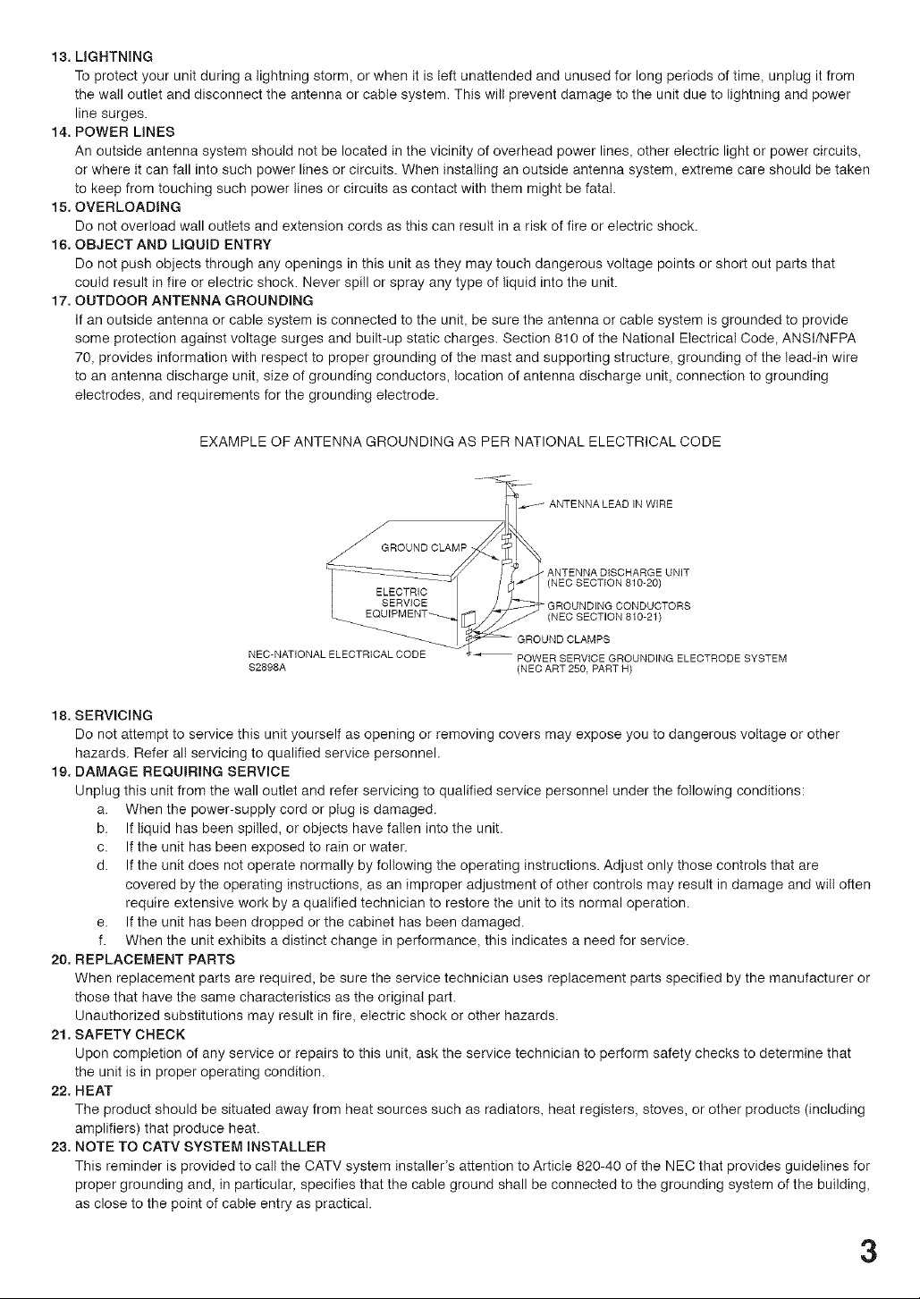
17. OUTDOOR ANTENNA GROUNDING
If an outside antenna or cable system is connected to the unit, be sure the antenna or cable system is grounded to provide
some protection against voltage surges and built-up static charges. Section 810 of the National Electrical Code, ANSI/NFPA
70, provides information with respect to proper grounding of the mast and supporting structure, grounding of the lead-in wire
to an antenna discharge unit, size of grounding conductors, location of antenna discharge unit, connection to grounding
electrodes, and requirements for the grounding electrode.
EXAMPLE OF ANTENNA GROUNDING AS PER NATIONAL ELECTRICAL CODE
ANTENNA LEAD IN WIRE
/_GROUND CLAMP
ANTENNA DISCHARGE UNIT
(NEC SECTION 810-20)
GROUNDING CONDUCTORS
(NEC SECTION 810-21)
NEC-NATIONAL ELECTRICAL CODE
$2898A
POWER SERVICE GROUNDING ELECTRODE SYSTEM
(NEC ART 250, PART H)
18. SERVICING
Do not attempt to service this unit yourself as opening or removing covers may expose you to dangerous voltage or other
hazards. Refer all servicing to qualified service personnel.
19. DAMAGE REQUIRING SERVICE
Unplug this unit from the wall outlet and refer servicing to qualified service personnel under the following conditions:
a. When the power-supply cord or plug is damaged.
b. If liquid has been spilled, or objects have fallen into the unit.
c. If the unit has been exposed to rain or water.
d. If the unit does not operate normally by following the operating instructions. Adjust only those controls that are
covered by the operating instructions, as an improper adjustment of other controls may result in damage and will often
require extensive work by a qualified technician to restore the unit to its normal operation.
e. If the unit has been dropped or the cabinet has been damaged.
f. When the unit exhibits a distinct change in performance, this indicates a need for service.
20. REPLACEMENT PARTS
When replacement parts are required, be sure the service technician uses replacement parts specified by the manufacturer or
those that have the same characteristics as the original part.
Unauthorized substitutions may result in fire, electric shock or other hazards.
21. SAFETY CHECK
Upon completion of any service or repairs to this unit, ask the service technician to perform safety checks to determine that
the unit is in proper operating condition.
22. HEAT
The product should be situated away from heat sources such as radiators, heat registers, stoves, or other products (including
amplifiers) that produce heat.
23. NOTE TO CATV SYSTEM INSTALLER
This reminder is provided to call the CATV system installer's attention to Article 820-40 of the NEC that provides guidelines for
proper grounding and, in particular, specifies that the cable ground shall be connected to the grounding system of the building,
as close to the point of cable entry as practical.
3
Page 4
Contents
o.s J
IMPORTANT SAFEGUARDS ........................................................ 2
Contents ........................................................................................ 4
Features ........................................................................................ 5
Power sou rce ................................................................................ 5
Parts and functions ........................................................................ 6
Remote control .............................................................................. 7
Antenna connections ..................................................................... 8
Cable TV connections ................................................................... 9
Connections to other equipment ................................................. 10
Selecting the VIDEO INPUT source ............................................ 12
Setting the language ................................................................... 13
Memorizing channels .................................................................. 14
IOPERATION J
TV operation................................................................................I7
SettingtheV-Chip.......................................................................19
Settingtheclock..........................................................................23
Settingthepicturesize................................................................24
Picture control adjustment/Resetting your picture adjustment ....25
Closed Caption ............................................................................ 26
CC advanced ............................................................................... 28
Selecting Stereo/Second Audio Program (SAP) ......................... 29
Selecting the audio language (DIGITAL MODE) ......................... 30
Checking the Digital-signal strength (DIGITAL MODE) .............. 31
Using the auto shut off feature .................................................... 32
IoT.E.s 1
Troubleshooting ........................................................................... 33
SPECIFICATIONS ....................................................................... 34
LIMITED WARRANTY ................................................................. 35
4
Page 5

Features
Nigh Quality Picture Horizontal Resolution more than 500 lines exceeds Super VNS (400 lines) or Laser
Disc (430 lines) in resolution.
• integrated Digital Tuner =You can view digital broadcasts without using a Digital TV Set-Top Box.
• Closed Caption Decoder With Full Text Mode - Displays text captions or full screen text on the screen for
hearing impaired viewers.
Picture Adjustments Using The Remote Control - The On-Screen display allows precise remote control
adjustment of BRIGHTNESS, CONTRAST, COLOR, TINT and SHARPNESS.
Programmable TV Sleep Timer - Operable from the remote control, the TV can be programmed for up to
120 minutes to turn off automatically.
V-Chip - The V-Chip function can read the rating of a TV program or movie content if the program is encoded
with this information. V-chip will allow you to set a restriction level.
Stereo/SAP Reception - This TV is designed to receive stereo and second audio program (SAP) broadcasts
where available.
S=Video/Component Video jacks - A VCR, DVD player, satellite receiver or other audio/video component
can be connected to this unit.
Video Input Jacks - This unit is equipped with 3 types of video input jacks. The component video in jacks
and S-video in jack enable you to watch the DVD player or the video devices with a high quality picture.
On-Screen 3 Language Display - You can select one of 3 languages, English, Spanish or French for on-
screen programming.
Power source
AC Outlet
Wider Hote _-'_-_"_--_
Polarized AC Cord Plug
(One blade is wider than the other)
TO USE AC POWER SOURCE
Use the AC polarized line cord provided for operation on AC. Insert
the AC cord plug into a standard 120V 60Hz polarized AC outlet.
NOTES:
• Never connect the AC line cord plug to other than the specified
voltage (120V 60Hz). Use the attached power cord only.
• If the polarized AC cord does not fit into a non-polarized AC
outlet, do not attempt to file or cut the blade. It is the user's
responsibility to have an electrician replace the obsolete outlet.
• If you cause a static discharge when touching the unit and the
unit fails to function, simply unplug the unit from the AC outlet
and plug it back in. The unit should return to normal operation.
5
Page 6

Parts and functions
Front
POWER button
Remote sensor AUDIO (L/R)/VIDEO IN jacks (VIDEO2)
*CHANNEL A/V buttons *VOLUME A/V buttons
* To display the menu screen.
Press both VOLUME A/V buttons at the same time to display the menu screen.
CHANNEL A/V buttons and VOLUME A/V buttons can be used to select the desired setting during the menu
screen operations.
ResF
RF IN (VHF/UHF)jack
S-VIDEO IN jack
AC power cord
AUDIO (L/R) OUT jacks
6
AUDIO (L/R)NIDEO IN jacks
(VIDEO1)
COMPONENT IN jacks
Page 7

©
b ob
bbb
bbb
_]EEP MUTE
6--
7
8--
1. POWER Button - Press to turn the power on/off to the
TV.
2. Direct Channel Selection Buttons (0-9) - Allow direct
access to any channel.
3. -/DISPLAY Button - When the TV is receiving an analog
signal pressing this button will display the current
information on-screen. When the TV is receiving a
digital signal, pressing this button once will display the
digital information on-screen; pressing it a second time
-®®Q
ANA 0@/ CLOSED
TV/AV DiGiTAL OA_TION
Before using the remote control, batteries must first be
HOW TO iNSTALL BATTERIES
1. Open the battery compartment cover.
--9
--10
--11
12
13
14
15
Remote control
will display the anatog information on-screen. To remove
the display from the screen, press this button again. This
button is also the "-" button used when selecting digital
channels.
4. SLEEP Button - To set the TV to turn off after a preset
amount of time, press the SLEEP button. The clock will
count up 10 minutes each time the button is pressed in the
order of 0, 10, 20, ...100, 110, 120. After the sleep time is
programmed, the display will disappear then reappear
momentarily every ten minutes to remind you the sleep timer
function is operating. To confirm the sleep time setting,
press the SLEEP button once and the remaining time will
be momentarily displayed. To cancel steep time, press the
SLEEP button repeatedly until the display turns to 0.
5. VOL (VOLUME) +/- Buttons - Press the + button to
increase, or the "-" button to decrease the volume level.
Use to select the desired setting during the menu screen
operation.
6. MENU/ENTER Button - Press to display the menu screen.
While in the on-screen menu, press to enter or select
options.
7. EXIT Button = Press to exit the menu screen.
8. TV/AV Button - Press this button to display SOURCE
SELECTION menu to select the video input source.
9. QUICK VIEW Button - This button allows you to go back to
the previous channel selected by pressing the QUICK VIEW
button. Press this button again to return to the channel you
were watching.
10. MUTE Button - To turn off the sound, press this button once.
The TV will be silenced and the symbol "MUTE" will appear
on the screen. The muting feature can be released by pressing
the MUTE button again or one of the VOL + or - buttons.
11. CH (CHANNEL) A/V Buttons- Press the A button to
change to a higher numbered channel set into memory.
Press the V button to change to alower numbered channel
set into memory. Use to select the desired setting during
the menu screen operation.
12. PICTURE SIZE Button - Press to change the picture size.
13. AUDIO Button - Press to select the desired audio setting.
14. CLOSED CAPTION Button - Press this button to display
CLOSED CAPTION menu.
15. ANALOG/DIGITAL Button -Press to select analog/digital mode.
installed.
Use two "AAA" size batteries (not supplied). The batteries
may last approximately one year depending on how much
the remote control is used. For best performance, it is
recommended that batteries should be replaced on a yearly
basis, or when the remote operation becomes erratic. Do not
mix old and new batteries or different types.
2. Install two "AAA" batteries (not supplied).
3. Replace the battery compartment cover.
BATTERY PRECAUTIONS
These precautions should be followed when using batteries
in this device:
• Use only the size and type of batteries specified.
• Be sure to follow the correct polarity when installing the
batteries as indicated in the battery compartment.
Reversed batteries may cause damage to the device.
• Do not mix different types of batteries together (e.g. Alkaline
and Carbon-zinc) or old batteries with fresh ones.
• If the device is not to be used for a long period of time,
remove the batteries to prevent damage or injury from
possible battery leakage.
• Do not try to recharge batteries not intended to be recharged;
they can overheat and rupture (follow battery manufacturer's
directions).
7
Page 8
Antenna connections
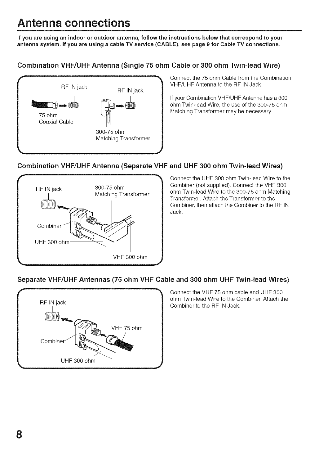
if you are using an indoor or outdoor antenna, follow the instructions below that correspond to your
antenna system, if you are using a cable TV service (CABLE), see page 9 for Cable TV connections.
Combination VHF/UHF Antenna (Single 75 ohm Cable or 300 ohm Twin-lead Wire)
Connect the 75 ohm Cable from the Combination
VHF/UHF Antenna to the RF IN Jack.
Ifyour Combination VHF/UHF Antenna has a 300
ohm Twin-lead Wire, the use of the 300-75 ohm
75ohm
Coaxial Cable IJI
I RF IN jack RF IN jack
Combination VHF/UHF Antenna (Separate VHF and UHF 300 ohm Twin-lead Wires)
- F IN jack 300-75 ohm -_
300-75 ohm
Matching Transformer
Matching Transformer may be necessary.
Connect the UHF 300 ohm Twin-lead Wire to the
Combiner (not supplied). Connect the VHF 300
ohm Twin-lead Wire to the 300-75 ohm Matching
Transformer. Attach the Transformer to the
Combiner, then attach the Combiner to the RF IN
Jack.
(_r,,,_ Matching Transformer /
Separate VHF/UHF Antennas (75 ohm VHF Cable and 300 ohm UHF Twin-lead Wires)
Connect the VHF 75 ohm cable and UHF 300
RF IN jack
UHF 300 ohm
ohm Twin-lead Wire to the Combiner. Attach the
Combiner to the RF IN Jack.
8
Page 9
Cable TV connections
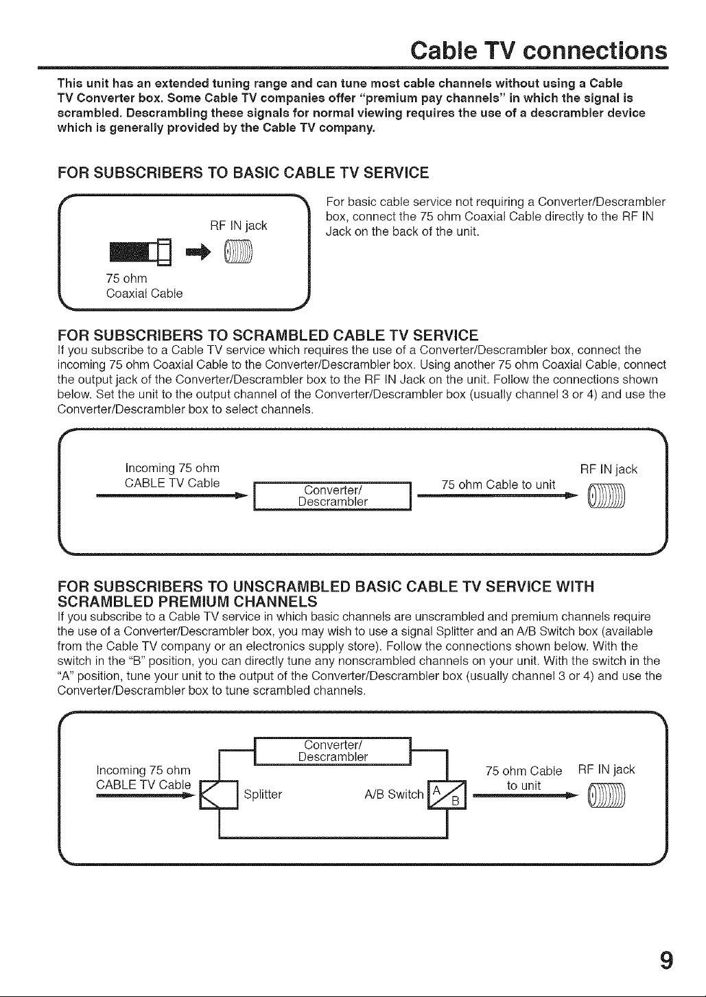
This unit has an extended tuning range and can tune most cable channels without using a Cable
TV Converter box. Some Cable TV companies offer "premium pay channels" in which the signal is
scrambled. Descrambling these signals for normal viewing requires the use of a deecrambler device
which is generally provided by the Cable TV company.
FOR SUBSCRIBERS TO BASIC CABLE TV SERVICE
r
RF IN jack
75 ohm
Coaxial Cable
For basic cable service not requiring a Converter/Descrambler
box, connect the 75 ohm Coaxial Cable directly to the RF IN
Jack on the back of the unit.
FOR SUBSCRIBERS TO SCRAMBLED CABLE TV SERVICE
If you subscribe to a Cable TV service which requires the use of a Converter/Descrambler box, connect the
incoming 75 ohm Coaxial Cable to the Converter/Descrambler box. Using another 75 ohm Coaxial Cable, connect
the output jack of the Converter/Descrambler box to the RF IN Jack on the unit. Follow the connections shown
below. Set the unit to the output channel of the Converter/Descrambler box (usually channel 3 or 4) and use the
Converter/Descrambler box to select channels.
r Incoming 75 ohm RF IN jack '_
_,_ CABLE 3V Cable i DC°nvem_[/r ] 75 ohm Cable to unit _-_ J
FOR SUBSCRIBERS TO UNSCRAMBLED BASIC CABLE TV SERVICE WITH
SCRAMBLED PREMIUM CHANNELS
If you subscribe to a Cable TV service in which basic channels are unscrambled and premium channels require
the use of a Converter/Descrambler box, you may wish to use a signal Splitter and an A/B Switch box (available
from the Cable TV company or an electronics supply store). Follow the connections shown below. With the
switch in the "B" position, you can directly tune any nonscrambled channels on your unit. With the switch in the
"A" position, tune your unit to the output of the Converter/Descrambler box (usually channel 3 or 4) and use the
Converter/Descrambler box to tune scrambled channels.
Incoming 75 ohm
CABLE TV Cable
Converter/ L,_
DescrambleL J / 75 ohm Cable RF IN jack
plitter
A/B Switch _=J_ to unit
9
Page 10

Connections to other equipment
The exact arrangement you use to interconnect various video and audio components to the TV is dependent
on the model and features of each component. Check the Owner's Manual provided with each component for
the location of video and audio inputs and outputs.
The connection diagrams below are offered as suggestions. You may need to modify them to accommodate
your particular assortment of components. The diagrams are intended to show component video and audio
interconnections only.
To connect the TV to a VCR
To connect the TV to a VCR with an S-Video cord
If you connect a VCR with a S-VIDEO cord to the S-VIDEO IN jack on the rear of the TV, you must also connect
the audio cords to the AUDIO IN jacks on the rear of the TV. The S-VIDEO cord only carries the video signal.
The audio signal is separate.
To S-VIDEO OUT
l? ToAUD,OOUT ...........................";:
AUDIO cord (not supplied) _ {.'D I_,,,,[_© "©' I-©H
To AUDIO IN i _t°'_ I _O'© | /J
S-VIDEOcord(notsupplied) _ ( " i_@'o'o polll
To S-VIDEO IN Rear of the TV
NOTE:
When the S-video cord and the video cord are connected to each jack at the same time, the S-video cord takes
precedence over the video cord.
To connect the iV to a DVD player/Satellite receiver
If your DVD playeror Satellite receiverhas a S-Videooutjack, connect cordsas shown.
T° S-VIDEO OUT 0 _ T° AUD]O OUT _ ................................................. IN........................... _T::_
| T ToAUDIO IN , ,_ ,_
| _ot SUpPUed)f--o, I _,<;'_ %@1 /.. I
To S-VIDEO IN Rear of the TV
10
Page 11

Connections to other equipment (continued)
To connect the TV to a DVD player with component video
If your DVD player has com )orient video out jacks, connect your TV to a DVD player using a component video
cord. It can greatly enhance picture quality and performance.
oA o'OO Ttl
Y PB_ TO COMPONENT OUT
/
VIDEO cord (not supplied) I....... I _o_ i
AUDIO cord (not supplied) C_ ,_[@ I©]111
To COMPONENT IN _:_ "_ _
NOTE:
This unit is only capable of displaying 480i interlaced signal when connected to a digital device with component video
outputs. If you input a 480p, 720p or 1080i signal to the component video inputs, "COMPONENT" and "NO SIGNAL
OR NOT SUPPORTED VIDEO RESOLUTION" will be displayed on a black screen, if this screen appears, set the
digital device's component output to 480i.
To connect the TV to a set-top box
If you connect a set-top box, connect your TV to it by using a component video cord.
,,, _ out
Rear of the TV
o ool
To AUDIO OUT _ vp_p_ To COMPONENT OUT
J J
/ VIDEO cord (not supplied) _ ...... _1_ 1
_UDIO cord (not supplied) _ i O _'_1_ i©lil :,
NOTE:
This unit is only capable of displaying 480i interlaced signal when connected to a digital device with component video
outputs. If you input a 480p, 720p or 1080i signal to the component video inputs, "COMPONENT" and "NO SIGNAL
OR NOT SUPPORTED VIDEO RESOLUTION" will be displayed on a black screen, if this screen appears, set the
digital device's component output to 480i.
To connect an audio system
i i
i
Amplifier
l_ BBBB_ooo 0 ooo
To AUDIO IN
AUDIO cord (not supplied)
¢
To AUDIO OUT
Rear of the TV
Rear of the TV
11
Page 12

Connections to other equipment (continued)
To connect the TV to a camcorder
To playback from a camcorder, connect the camcorder to the TV as shown.
Front of the TV
i__ VIDE i INm (ao'_o) L--AUDIO IN--R
©©©
fff t f t
AUDIO/VIDEO cord (not supplied)
To connect the TV to a Game
The TV can also be used as a display device for many video games. However, due to the wide variety of signals
generated by these devices and subsequent hook-up variations required, they have not all been included in
the suggested connection diagrams. You'll need to consult each component's Owner's Manual for additional
information.
Front of the TV
VIDEO INto {MONO) L--AUDIO IN--R
TV GAME
fff f f f
ToAUDIONIDEO OUT !_)
AUDIONIDEO cord (not supplied)
Selecting the VIDEO input source
Press TV/AV to view a signal from another device connected to your TV, such as a VCR or DVD player. You can
select "ANALOG", "DIGITAL", "VIDEO1", "VIDEO2" (on the front panel), or "COMPONENT" depending on which
input jacks you used to connect your devices.
Pressing TV/AV on the remote control displays the current signal source.
Press ^ / M or the number buttons (0-4) to select desired mode.
SoURC_S_LECTIQ_
_, COMPONENT
12
Page 13

Setting the language
You can choose from three different
languages (English, French and
Spanish) for the on-screen displays.
Press MENU/ENTER. The menu screen will appear.
2 Press < or > to select (SETUP)
menu.
Press ^ or v to select
"LANGUAGE/IDIOMA/LANGUE".
Then press > to display the
LANGUAG E/IDIOMA/LANGU E menu.
Press ^ or v to select the desired
language: English (ENGLISH), French
(FRANOAIS) or Spanish (ESPANOL).
CLOCKS_T
c_ocK s_T i,
TWCA_L_ _ CA_L_
LANgUaGe/
_CA_UE
NOTE:
If no buttons are pressed for more
than 60 seconds, the MENU screen
will return to normal TV-operation
automatically.
Press MENU/ENTER repeatedly until the menu screen is cleared.
Otherwise, press EXiT to return to the normal screen immediately.
13
Page 14

Memorizing channels
This TV is equipped with a channel memory feature which allows channels to skip up or down to the next channel set
into memory, skipping over unwanted channels. Before selecting channels, they must be programmed into the TV's
memory. To use this TV with an antenna, set the TV/CABLE menu option to the TV mode. When shipped from the
factory, this menu option is in the CABLE mode.
TV/CABLE selection
Press MENU/ENTER. The menu screenwill appear.
2 Press<or>toselect(SETUP)
menu.
_A_GUAG_/
=_=O_A/LANGUE
C_OCKS_T
TV'_ASL_ _ _A_L_
_UTOC_ M_m_Y
Press ^ or v to select "TV/CABLE".
L_N_UAGE/
C_OCKS_T
AUTOCHM_MO_
NOTE:
it may take a few seconds for a digital
channel picture to appear on screen
after being selected.
,4
_l'Press < or >to select"TV'or
"CABLE".
Press MENU/ENTER repeatedly until the menu screen is cleared.
Otherwise, press EXIT to return to the normal screen immediately.
CABLE CHART
The chart below is typical of many cable system channel allocations.
Number on this TV 14 15 t6 17 18 19 20 21 22
Corresponding CABLE channel A B C D E F G H I
23 24 25 26 27 28 29 30 31 32 33 34 35 36 37 38 39 40
J K L M N O P Q R S T U V W AA BB CC DD
41 42 43 44 45 46 47 48 49 50 51 52 53 54 55 56 57 58
EE FF GG HH II JJ KK LL MM NN CO PP QQ RR SS TT UU VV
59 60 61 62 63 64 65 66 67 68 69 70 7t 72 73 74 75 76
WW AAA BBB CCC DDD EEE FFF GGG HHH III JJJ KKK LLL MMMNNN OOO PPP QQQ
77 78 79 80 81 82 83 84 85 86 87 88 89 90 91 92 93 94
RRR SSS Tqq _ UUU VVVWWWXXX YYY ZZZ 86 87 88 89 90 91 92 93 94
95 96 97 98 99 100 101 102 103 104 105 106 107 108 109 110 111 112
A-5 A-4 A-3 A-2 A-1 100 101 102 103 104 105 106 107 108 109 110 1tl 112
113 114 115 116 117 118 119 120 121 t22 123 124 125 01
113 114 115 116 117 118 119 120 121 t22 123 124 125 5A
14
Page 15

Memorizing channels (continued)
Automatic memory tuning
Press MENU/ENTER. The menu screenwill appear.
2 Press < or > to select (SETUP)
menu, then press ^ or v to select
"AUTO CH MEMORY".
Press >. The TV will begin
memorizing all the channels
available in your area.
After finishing Analog Tuning,
Digital Tuning starts automatically.
° It may take from 15 minutes to 30
minutes to complete memorizing
digital cable channels. Depending on the reception condition,
a BAR display may not advance for several minutes.
LA_GUA_I
_D=OUA/L_N_UE
CLOCKS_T
TVlC_BL_ _ CABL_
t _T,_o[,_,o_,_,Y,
t
NOTES:
• Memorizing channels is best
accomplished during evening
"PRIMETIME" hours, as more stations
are broadcasting digital signals.
Memorizing channels can only be
accomplished while a station is
broadcasting a digital signal to set
that channel into memory.
• If you are unsure of the digital channels
available in your area you may visit
www.antennaweb.org to receive a list
based on your address or zip code.
Should you require further assistance
you may call our toll-free customer
service line at 1-800-289-0980.
• New digital channels may be added
to your area periodically, it is
recommended that you perform the
"AUTO CH MEMORY" procedure
regularly.
To add or delete channels (ANALOG MODE)
Press ANALOG/DIGITAL to select the analog mode.
Press MENU/ENTER. The menu screen appears.
3Press < or > to select (OPTION)
menu, then press ^ or v to select
"ADD/DELETE".
Press >. The ADD/DELETE menu
appears.
Select the desired channel to be
memorized or deleted using ^ or v.
Press < or > to select "ADD" or "DELETE".
Repeat steps 5-6 for other channels you want to add or delete.
Press MENU/ENTER repeatedly until the menu screen is cleared.
Otherwise, press EXIT to return to the normal screen immediately.
sA_'"_' __ _*OFF
¢LOS_ CA_TIO_
VC_I_
_U_OS_U__O_ _ O_
A_ALO_
15
Page 16

Memorizing channels (continued)
To add or delete channels (DIGITAL MODE)
Press ANALOG/DIGITAL to select the digital mode.
Press MENU/ENTER. The menu screen appears.
O Press < or > to select (OPTION)
menu, then press ^ or v to select
"DIGITAL SETUP".
AUTO_HUTOF_ > OF_
Press >. The DIGITAL SETUP menu
appears.
Press A or v to select "ADD/DELETE",
DI_ITALS_TUP
CC ADWNC_ >
AUDIOLANGUA_ >
SI_ALM_TER >
A_I_LET_ _TV
then press >. The ADD/DELETE (DTV)
menu appears.
Press ^ or v to select "ADD/DELETE", then press >.
Select the desired channel to be memorized ordeleted using ^ or v.
Press < or > to select "ADD" or "DELETE".
Repeat steps 7-8 for other channels you want to add or delete.
16
0 Press MENU/ENTER repeatedly until the menu screen is cleared.
To add a digital channel you are watching
Select the digital channel you want to add. Press ^ or v to select
"ADDING CHANNEL" as in step 6 above, then press>.
Page 17

NOTES:
• If a channel with no broadcast is
selected, the sound will automatically
be muted.
• If a station being viewed stops
broadcasting, the TV will automatically
shut itself off after 15 minutes.
• It may take a few seconds for a
digital channel picture to appear on
screen after being selected.
TV operation
To turn on the TV, press POWER.
Adjust the volume level by pressing VOL
+ or -. The volume level will be indicated
on the screen by green bars. As the
volume level increases, so do the number
of bars. If the volume decreases, the
number of green bars also decreases.
Set the TV/CABLE menu option to the
appropriate position (see page 14).
Press the Direct Channel Selection
buttons to select the channel.
To select analog channels
When tile TV/CABLE menu option is
in the TV position, all channels can be
instantly selected by using two buttons.
(For example, to select channel 2, press
"O", then "2". ifyou press only "2", channel selection will be delayed
for a few seconds.)
For channels 10 and above, press the 2 digits in order.
When the TV/CABLE menu option is in the CABLE position,
channels can be selected as follows:
1-9: Press 0 twice, then 1-9 as needed.
10-12: Press 0, then remaining 2 digits.
13-99: Press the 2 digits inorder.
100-125: Press the 3 digits in order.
To select digital channels
Press the channel number in order.
When "-" is contained in the channel number, press the first digits,
then press "-/DISPLAY", followed by the remaining 3 digits.
(Example, to select channel 015-001, press 015 - 001 .)
, If a channel is selected with only audio content, "AUDIO ONLY"
, If a channel is selected with a weak digital signal, "DIGITAL
, If a channel is selected to which you have not subscribed,
VHF/UHF/CABLE CHANNELS
Example, to select channel 2, press 002.
Example, to select channel 12, press 012.
Example, to select channel 36, press 36.
Example, to select channel 120, press 120.
will be displayed on the screen.
CHANNEL SIGNAL STRENGTH IS LOW" will be displayed on
the screen.
Ifthe digital channel has the same analog channel, you may be
able to watch the same channel with analog.
"DIGITAL CHANNEL IS ENCRYPTED" will be displayed on the
screen.
TV
VHF
2-13
UHF
14-69
CABLE
VHF
2-13
STD/HRC/IRC
14-36 (A) (W)
37-59 (AA) (WW)
60-85 (AAA) (ZZZ)
86-94 (86) (94)
95-99 (A-5) (A-l)
100-125 (100) (125)
01 (5A)
17
Page 18

TV operation (continued)
CH^/v
Press and release OH ^ or v.
The channel automatically stops at the next
channel set into memory.
For proper operation, before selecting
channels, they should be set into the
memory. See pages 14 - 16
"Memorizing channels".
DISPLAY
Press -/DISPLAY to display the current
information on the screen.
When the TV receives a digital signal,
the digital information will appear.
• Broadcast program name
• Station name • Remaining time
• Audio language . Program name
• V-CHIP RATING . V-Chip mark
A_ALCe
CH 0_
NOTE:
After 10 seconds, DISPLAY screen
will return to normal TV-operation
automatically, when a Digital signal is
received.
After 4 seconds, DISPLAY screen
will return to normal TV-operation
automatically, when an Analog signal is
received.
When the TV receives an Analog signal,
press -/DISPLAY again, the analog
information will appear.
STEReOSAp
• Clock
• Channel number or VIDEO mode selected
• Stereo or SAP (second audio program)
audio status
• Picture size
Press -/DISPLAY again to clear the call display.
QUICK VIEW
This button allows you to go back to the
last channel selected by pressing QUICK
VIEW. Press QUICK VIEW again to return
to the last channel you were watching.
MUTE
Press MUTE to switch off the sound.
The unit's sound will be silenced and
"MUTE" will appear on the screen.
The sound can be switched back on by
pressing this button again or one of the
VOL + or - buttons.
SLEEP
To set the unit to turn off after a preset amount
of time, press SLEEP on the remote control.
The clock will count up 10 minutes for each
press of the SLEEP button (0, 10, 20, ...100,
110, 120).
After the sleep time is programmed, the
display will appear briefly every ten minutes to
remind you that the sleep timer is operating.
To confirm the sleep timer setting, press SLEEP and the remaining
time will be displayed for a few seconds. To cancel the sleep timer,
press SLEEP repeatedly until the display turns to 0.
_ALOS
CH 0_
ANALO_
18
Page 19

Setting the V=Chip
An age limitation can be set to restrict children from viewing or hearing violent scenes or pictures that you may
choose to exclude. The restriction applies to "TV RATING" and "MOVIE RATING" if this data is transmitted.
You may set this restriction separately. To use the V-Chip function, you must register a password.
To set a password
Press MENU/ENTER. The menu screenappears.
2 Press < or > to select (OPTION)
menu, then press ^ or M to select
"V-CHIP".
Press >. The password entering
screen appears.
Select and enter a password (4 digits)
using the number buttons (0-9), then
press MENU/ENTER
she _ o_FCLOSE_CA_TIr_N
_UTOSH_TO_F _ O_F
v cHl_ s_T
NOTES:
• If you forget the password, contact
Customer Service at 1-800-289-0980
for assistance. Your original remote
control will be required.
• To avoid forgetting the password, write
it down and keep it in a safe place.
">k"appears instead of the number.
Enter the same password again to
confirm, then press MENU/ENTER.
The password is now set and the
V-CHIP menu appears on the screen.
v cHl_ s_T
PAS_WOR_
19
Page 20

Setting the V-Chip (continued)
To
set the V-CHIP
1
Press MENU/ENTER. The menu screen appears.
2
Press < or > to select {: (OPTION)
menu.
3
Press ^ or v to select "V-CHIP".
4
Press > to display the password
entering mode. Use number buttons
(0-9) to enter your password, then
press MENU/ENTER The V-CHIP
menu appears.
5
Press ^ or v to select "V-CHIP SET",
then press < or >. The V-CHIP SET
menu appears.
6
Press ^ or M to select "TV RATING",
then press < or > to display the desired
rating.
OFF : TV RATING is not set
TV-Y : All children
TV-Y7 : 7 years old and above
TV-G : General audience
TV-PG : Parental guidance
TV-14 : 14 years old and above
TV-MA : 17 years old and above
, When you select TV-Y7, TV-PG,
TV-14, or TV-MA, press -/DmSPLAY
to further define the rating.
Press ^ or ',/to select the desired rating you want.
Press < or > to select the setting "ON" or "OFF".
_/E_TER
VCHit
VCHIt S_
To use the TV after the TV is protected.
When aprogramis receivedthatis blocked
by the V-Chip,enterthe password,then press
MENU/ENTER When thepasswordisentered
correctlythe protectionwiIIbe temporarily
overridden.
IftheTV isturned off, or the channelis changed
theV-Chip restrictionwill be reactivated.
NOTES:
TheV-Chipfunction isactivatedonlyon
programsand inputsourcesthat includea
rating signal.
• TheV-CHIPSET(DTV) willonly be selectable
whenthe unitreceivesadigitalbroadcastusing
thenewrating system.It maytakeseveral
minutesforthe initial V-ChipSet-upto complete.
Atthis time some stationsare still developing
thissignal,inthose casesthe V-CHIP SET
(DTV)will notfunction.
20
7
Press ^ or v to select "MOVIE
RATING", then press ),.
The RATING SET menu appears.
8
Press ^ or v to select the rating,
then press < or > to select "ON" or
"OFF" for each rating.
G : All ages
PG : Parental guidance
PG-13
R
N0-17
X
9
Press MENU/ENTER twice to return to the V-CHIP menu, then
press ^ or v to select "V-CHIP".
10
Press < or > to select "ON". Your settings are now set into
memory.
11
Press MENU/ENTER repeatedly until the menu screen is cleared.
Otherwise, press EXIT to return to the normal screen immediately.
: Parental guidance less than 13 years old
: Under 17 years old parental guidance suggested
: 17 years old and above
: Adult only
_TI_ SET
Page 21

Setting the V-Chip (continued)
To change the password
Press MENU/ENTER. The menu screenappears.
2 Press < or > to select (OPTION)
menu, then press ^ or v to select
"V-CHIP".
A_/_ELETE
_AP _ OFF
CLO_ CAPTIO_
AUTOS_'UTOF_ _ O_
Press > to display the password
entering mode. Use the number
buttons (0-9) to enter your password,
then press MENU/ENTER.
The V-CHIP menu appears.
Press ^ or v to select "CHANGE
PASSWORD", then press >.
Enter a new password using the
number buttons (0-9), then press
MENU/ENTER.
Enter the same password again to
confirm, then press MENU/ENTER.
V C_IP
CHA"G_ASSWO_
V C_I_ SET
C_IANG__ASSWO_
Press MENU/ENTER repeatedly until the menu screen is cleared.
Otherwise, press EXIT to return to the normal screen immediately.
21
Page 22

Setting the V-Chip (continued)
Downloading the additional V-Chip rating system
As a supplement to the standard V-Chip rating system, your television
will be able to download an additional rating system, if such a system
becomes available in the future.
To download the additional V-Chip rating system
(when available)
Press ANALOG/DIGITAL to select the digital mode.
2 Press MENU/ENTER, then press < or > to display (OPTION)
menu.
Press ^ or v to select "V-CHIP",
then press >.
_IGITALS_TUP
aUTOSI_UTO_F _"OFt
Use the Channel Number buttons
(0-9) to enter your password.
Press MENU/ENTER.The V-CHIP
menu appears.
NOTES
• You can only downloadthe additional V-Chip
rating system when yourTV isreceiving a
digital signal
• When you download the additional rating
system, it may take some time for the
downloadto occur.
• The V-Chiprating information andsystem
are not determined orcontrolledby the TV
• The standardV-Chip rating system is
availablewhether yourTV is receiving a
digital signal or not, andwill block both
analog and digital programs.To set the
restriction level using thestandard V-Chip
rating system, selectV-CHIP SETin step5
• The downloadableV-Chip rating system
is an evolving technology,and availability.
content, and format may vary.
• You cannot selectthisfeature ifthe TV is
not receiving a digitalsignal for the current
station.
Press ^ or v to select
"V-CHIP SET (DTV)", then press >.
If the TV is not storing the additional
rating system, the TV will begin
VC_IP
V ¢_P _ O_F
VC_IPs_r
v c_lP SET _TV
UPDAT_
downloading it, which may take
some time to be completed.
Press ^ or v to select "RRT SET", then then press >, and set
your preferred content rating limits for the additional rating system,
22
Page 23

Setting the clock
EXAMPLE: Setting the clock to "8:30 AM", 25 th (SUN) March, 2007.
1Press MENU/ENTER, then press < or > to select (SETUP)
menu.
Press ^ or v to select "CLOCK
SET". Then press >. The CLOCK
SET menu will appear.
LAN_UA_E/
I_IO_A/ LA_GUE
TV'CA_L_ _ CABLE
AUTOCHM_O_Y
NOTE:
After a power failure or disconnection
of the power, the clock settings will be
lost. In this case, reset the present
time.
Press < or> to set the MONTH,
then press v.
Set the DAY, YEAR and TIME as in
CLOCKS_T
_2t .......
CLO_KS_T
step 3.
After setting the date and time,
the clock will begin functioning
automatically.
Press MENU/ENTER repeatedly until the menu screen is cleared.
Otherwise, press EXIT to return to the normal screen immediately.
23
Page 24

Setting the picture size
You can view 480i format programs
in three picture sizes=4:3, 16:9
and ZOOM.
Selecting the picture size
You can change the picture size by pressing the PICTURE SIZE
button on the remote control.
_ 16:9
=='=_ 4:3
ZOOM
4:3 picture size
Tofill the screen, the top and bottom edges are extended more
widely though the center of the picture remains near former ratio.
i©©©i
. If receiving a 4:3 format program, the image is displayed its
originally formatted proportion.
16:9 picture size
This image will display the size of standard 16:9 with black bars at
the top and bottom.
NOTES:
• If receiving an Analog signal, you
can choose 4:3 or 16:9 picture size.
• If you are receiving a Digital signal in
the 4:3 format, you are restricted to
the 4:3 picture size.
• It receiving a Digital signal of 16:9,
you can choose 4:3, 16:9 or ZOOM.
24
©©©]
©©©
. If receiving a 4:3 format program, the image is displayed with
black bars at the top and bottom and stretched wider.
NOTE:
If a fixed black bar remains on the screen for long periods of time, the
image can become permanently engrained in the screen and cause
subtle but permanent ghost images. Never leave your TV on for an
extended period of time while displaying a stationary image(s).
ZOOM picture size (for 16:9 format programs)
The entire picture is uniformly enlarged--it is stretched the same
amount both wider and taller (retains its original proportion). The
right and left edges of the picture may be hidden.
Page 25

Picturecontroladjustment/Resettingyour picture adjustment
Picture control adjustment
Press MENU/ENTER, then press
< or > to select 'i _(PICTURE)
menu.
Press ^ or v to select the item
you want to adjust.
Press < or > to adjust the setting.
COLO_
TJ_T
S_PNESS
TI_T
S_PN_SS
BRIGHTNESS
CONTRAST
COLOR
TINT
SHARPNESS
<
decrease brightness
decrease contrast
paler color
reddish color tint
makes picture softer
increase brightness
increase contrast
brilliant color
greenish color tint
makes picture clearer
>
After you have made your selection, press EXIT to return to the
normal screen.
NOTE:
The CONTRAST default setting is set to maximum at the factory.
Resetting your picture adjustment
The RESET function returns your picture quality adjustments to the
following factory settings:
BRIGHTNESS .......... CENTER (0) TINT ..................... CENTER (0)
CONTRAST ................... MAX (32) SHARPNESS ...... CENTER (0)
COLOR ..................... CENTER (0)
Press MENU/ENTER, then press
< or > to select (PICTURE) menu,
COLO_
T_T
Press ^ or v to select "RESET", then press >.
25
Page 26

Closed Caption
WHAT iS CLOSED CAPTIONING?
This television has the capability to decode and display Closed Captioned television programs. Closed Captioning
will display text on the screen for hearing impaired viewers or it will translate and display text in another language.
Captions: This Closed Caption Mode will display text on the screen
in English or another language. Generally, Closed Captions in English
are transmitted on C1 and Closed Captions in other languages are
transmitted on C2.
Text: The Text Closed Caption Mode will usually fill 1/2 of the screen
with a programming schedule or other information.
To
turn on closed captions (ANALOG MODE)
1
Tune the television to the desired program in the analog mode.
2
Press MENU/ENTER, then press < or > to display (OPTION)
menu.
3
Press ^ or v to select "CLOSED
CAPTION".
4
Press >. The CLOSED CAPTION
menu appears.
NOTES:
• Depending on the broadcast signal,
some analog captions function with
a digital broadcast signal.
• This screen can be displayed by
pressing CLOSED CAPTION.
5
Press ^ or v to select the desired
closed caption mode, then press
MENU/ENTER.
sAP OFF
AUtO8_u1¸ OJ=_= _ 0_
CLOSEOCA_TION
TI
T2
_FF
NOTES:
• To view captions, select Cl or C2 (C1 displays translation of the
primary language in your area). If the program or video you selected
is not closed captioned, no captions will display on-screen.
• To view text, select T1 or T2. If text is not available in your viewing
area, a black rectangle may appear on-screen. If this happens, set
the Closed Caption feature to OFF.
Press MENU/ENTER repeatedly until the menu screen is cleared.
NOTES:
• If the program or video you selected is not closed-captioned, no captions will display on-screen.
• If text is not available in your viewing area, a black rectangle may appear on-screen. If this happens, set the Closed
Caption feature to "OFF".
• When selecting Closed Captions, the captioning will be delayed approx. 10 seconds.
• If no caption signal is received, no captions will appear, but the television will remain in the Caption Mode.
• Misspellings or unusual characters may occasionally appear during Closed Captioning. This is normal with Closed
Captioning, especially with live programs. This is because during live programs, captions are also entered live.
These transmissions do not allow time for editing.
• When Captions are being displayed, on-screen displays, such as volume and mute may be seen but may interfere with
Closed Captions.
• Some Cable TV systems and copy protection systems may interfere with the Closed Captioned signal.
• If using an indoor antenna or if TV reception is very poor, the Closed Caption Decoder may not appear or may appear
with strange characters or misspelled words. In this case, adjust the antenna for better reception or use an outdoor
antenna.
Otherwise, press EXIT to return to the normal screen immediately.
26
Page 27

Closed Caption (continued)
To turn on closed captions (DIGITAL MODE)
Tunethe television to the desired program inthe digital mode.
Press MENU/ENTER. The menu screen appears.
3 Press < or > to select (OPTION)
menu, then press ^ or v to select
"DIGITAL SETUP".
AUTOSHUTO_ _ O_
NOTE:
To turn the closed caption feature off,
select OFF in step 7, above.
Press >. The DIGITAL SETUP menu
appears.
Press ^ or v to select "CLOSED
CAPTION", then press ),.
The CLOSED CAPTION menu
appears.
• This screen can be displayed by
pressing CLOSED CAPTION.
Press ^ or v to select "ANALOG CAPTION" or "DIGITAL CAPTION".
Press < or > to select the desired closed caption mode.
Press MENU/ENTER repeatedly until the menu screen is cleared.
BIGTTALS_TU_
CLOS_DC_PT40_
_UD4OL_NGU_G_
CLOS_ CA_TION
Adjusting closed captioning
Closed captions are factory preset. However you can adjust them
individually. This feature is designed to customize digital captions only.
27
Page 28

CC advanced
Closed Captions are factory preset
however you can adjust them
individually as follows:
This feature is designed to customize Digital Captions only.
Tune the television to the desired program in the digital mode.
Press MENU/ENTER. The menu screen appears.
3Press < or > to select (OPTION)
menu, then press A or v to select
"DIGITAL SETUP".
Press >. The DIGITAL SETUP menu
appears.
Press A or M to select"CC
ADVANCED", then press >.
The CC ADVANCED menu appears.
AUTOSmUTOFT _ OFT
DIG,TALSETU_
CLOS_C_PTIO_
CC_W_CE_
_UDJOL_U_G_
SIG_LM_TE_
CCA_VANC_
NOTES:
• Do not set the Closed Caption
"TEXT COLOR" and
"BACKGROUND COLOR" as the
same color or you will not be able to
see the text.
• Do not set both the "TEXT OPACITY"
and the "BACKGROUND OPACITY"
to "TRANSPARENT" or you will not
be able to see the text.
28
Press ^ or M to select the item you want to adjust, then press _.
Press ^ or v to select the setting, then press MENU/ENTER
You can select from among the following items and parameters.
TEXT SIZE : AUTO, SMALL, STANDARD, LARGE
TEXT TYPE : AUTO, DEFAULT, MONO W. SERIF, PROP W.
SERIF, MONO W/O. SERIF, PROP W/O. SERIF,
CASUAL, CURSIVE, SMALL CAPITALS
TEXT EDGE : AUTO, NONE, RAISED, DEPRESSED, UNIFORM,
LEFT DROP SHADOW, RIGHT DROP SHADOW
TEXTCOLOR : AUTO, BLACK, WHITE, RED, GREEN, BLUE,
YELLOW, MAGENTA, CYAN
BACKGROUND COLOR : AUTO, BLACK, WHITE, RED, GREEN,
BLUE, YELLOW, MAGENTA, CYAN
TEXTOPACITY:AUTO, TRANSPARENT, TRANSLUCENT, SOLID,
FLASHING
BACKGROUND OPACITY: AUTO, TRANSPARENT,
TRANSLUCENT, SOLID, FLASHING
Press MENU/ENTER repeatedly until the menu screen is cleared.
Page 29

Selecting Stereo/Second Audio Program (SAP)
Selecting Stereo/Second Audio Program (SAP)
The multi-channel TV sound (MTS) feature provides high-fidelity
stereo sound. MTS also can transmit a second audio program (SAP)
containing a second language or other audio information.
When the TV receives a stereo or SAP broadcast, the word "STEREO"
or "SAP" displays on-screen every time you turn the TV on, change the
channel, or press -/DISPLAY.
To set the SAP
Press MENU/ENTER in the analog
mode, then press < or > to display
(OPTION) menu.
Press ^ or v to select "SAP",then
press < or > to select "ON" or"OFF".
Press MENU/ENTER repeatedly until the menu screen is cleared.
Otherwise, press EXIT to return to the normal screen immediately.
To listen to stereo sound
When the TV is turned on or a channel selection is made, the STEREO
will appear on the screen. This means that Stereo broadcasting is
available. You can enjoy stereo sound from the left and right speakers.
• When mono broadcasting is received, no indication is displayed.
• If the broadcasting signal is not strong enough or clear stereo sound is
not available, press AUDIO to change to mono sound. The noise
should be eliminated. Press it again to return to the stereo sound.
_4_ OFF
CLOSEDC_PtIO_
AUTOSHUTO_r • O_r
To listen to second audio program (SAP)
When the TV is turned on or a channel selection is made, SAP will
appear on the screen. This means that the Second Audio Program
broadcasting is available.
29
Page 30

Selecting the audio language (DiGiTAL MODE)
Selecting the audio language (DIGITAL MODE)
When two or more audio languages are included in a digital signal, you
can select one of the audio language.
To select the audio language
Tune the television to the desired program in the digital mode,
Press MENU/ENTER. The menu screen appears.
3Press < or > to select (OPTION)
menu, then press ^ or v to select
"DIGITAL SETUP".
AUTOSHUTO_* _ O_*
NOTE:
You can also display the AUDIO
LANGUAGE menu by pressing
"AUDIO" on the remote control.
Press >. The DIGITAL SETUP menu
appears.
Press ^ or v to select "AUDIO
LANGUAGE", then press > to display
the AUDIO LANGUAGE menu.
Press ^ / v or the number buttons (0-7) to select your desired
language, then press MENU/ENTER.
Press MENU/ENTER repeatedly until the menu screen is cleared.
DYGITAL_TU_
CCADW_C_
SIGNALMET_
AUD=OLA_UAG_
30
Page 31

Checking the Digital-signal strength (DiGiTAL MODE)
This television allows you to view
the digital signal meter for digital
channels.
To check the digital signal strength
Tunethe television to the desired program inthe digital mode.
Press MENU/ENTER. The menu screen appears.
3Press < or > to select (OPTION)
menu, then press ^ or v to select
"DIGITAL SETUP".
Press >. The DIGITAL SETUP menu
appears.
Press ^ or v to select "SIGNAL
METER", then press > to check the
digital-signal strength.
v.cH=_
AUTOSmUTO_ _ O_
CLOSEDCAPTIO_
CCADVANC_
AUdiOLANGVA_
SIG_ALMETE_
CHANN_L_IGITAL) _2-_
NOTES:
• Signal meter feature is not available
for analog channels.
• After 240 seconds, SIGNAL METER
screen will return to normal
TV-operation automatically.
Press MENU/ENTER repeatedly until the menu screen is cleared.
31
Page 32

Using the auto shut off feature
if the AUTO SHUT OFF feature is
ON, and a station being viewed
stops broadcasting, the TV will
automatically shut itself off after
15 minutes.
To use the auto shut off feature
Press MENU/ENTER. The Menu screenwill appears.
2 Press < or > to display (OPTION)
menu.
AD_m_L_T_
SAP _ O_
CLOS_BCA_TIO_
Press ^ or v to highlight "AUTO
SHUT OFF", then press < or > to
select "ON" or "OFF".
Press MENU/ENTER repeatedly until the menu screen is cleared.
Otherwise, press EXIT to return to the normal screen immediately.
SA_ O_F
32
Page 33

Troubleshooting
Use the following check list for troubleshooting when you have problems with your TV. Consult your local dealer or
service outlet if problems persist. Be sure all connections are properly made when using with other units.
€-SYMPTOMS
TV does not
operate.
Poor sound
or no sound.
Poor picture
or no picture.
Poor
reception on
some
channels.
Poor color or
no color.
Picture
wobbles or
drifts.
Digital
broadcasting
screen
crob!em:
POSSIBLE SOLUTIONS
• Make sure the power cord is plugged in.
• Try another AC outlet.
• Power is off, check fuse or circuit breaker.
• Unplug unit for an hour, then plug it back in.
• Station or CABLE experiencing problems,
tune to another station.
• Oheck sound adjustments (Volume and Mute).
• Check for sources of possible interference.
• Station or CABLE experiencing problems,
tune to another station.
• Make sure channels are set into memory.
• Check antenna or CABLE connections,
adjust antenna.
• Check for sources of possible interference.
• Check picture control adjustments.
• Station or CABLE experiencing problems,
tune to another station.
• Make sure channels are set into memory.
• Station is weak, adjust antenna to receive
desired station.
• Check for sources of possible interference.
• Station or CABLE experiencing problems,
tune to another station.
• Make sure channels are set into memory.
• Check picture control adjustments.
• Check antenna or CABLE connections,
adjust antenna.
• Check for sources of possible interference.
• Station or CABLE experiencing problems,
tune to another station.
• Make sure channels are set into memory.
• CABLE company is scrambling signal.
• Adjust antenna.
• Check digital signal strength.
_SYMPTOMS POSSIBLE SOLUTIONS
Check alt CABLE connections.
No CATV Set TV/OABLE menu option to the CABLE
reception, mode.
Horizontal or Check antenna connections, adjust or
diagonal bars re-direct antenna.
on screen. Check for sources of possible interference.
No reception Make sure TV/CABLE menu option is in the
above appropriate mode.
channel 13. If using antenna, check UHF antenna
No Remote
operation.
TV shuts off. Sleep Timer is set.
Closed - tuned is not closed captioned. Try another
Caption is channel.
not activated. Check CABLE connection or VHF/UHF
Display is not
shown in your
_anguage-
Station or CABLE system problems, try
another station.
connections.
Batteries are weak, dead or inserted incorrectly.
Remote is out of range, move closer to TV
(within 15 feet).
Make sure Remote is aimed at sensor.
Confirm there are no obstructions between
the Remote and the TV.
Make sure the power cord is plugged in.
No broadcast on station tuned.
Power interrupted.
TV station experiencing problems or program
antenna, reposition or rotate antenna.
Set closed caption decoder in the menu.
• select proper language in the menu options.
f,,fSANSUI
FOR C
| OR WRITE TO:
| ORION SALES, INC,
| 3471 N. UNION DR. I
I OLNE ,I,LI.OIS6245O I
I OR,. ORMAT,O OUP LINE. PLEASE IS,TOUR I
| WEBSITE AT I
www, orionealesinc.com
33
i
Page 34

SPECiFiCATiONS
Power supply:
Power Consumption:
Weight:
Dimensions:
Inputs:
Output: AUDIO:
Antennainput:
Picture Tube:
Tuner Type:
Receiving Channels:
VIDEO:
AUDIO:
S-VIDEO:
COMPONENT:
AC 120V, 60Hz
Operation 110Watts
Stand by 3W
87.1 Ibs (39.5 kg)
Width: 25-9/16 inches (650.0 mm)
Height: 22-1/2 inches (571.5 mm)
Depth: 20-1/8 inches (510.5 mm)
1 V (p-p)/75 ohms
-8 dBm/50k ohms
Y: 1 V (p-p), 75 ohms
C: 0.286 V (p-p), 75 ohms
Y: 1 V (p-p), 75 ohms
PR: 0.7 V (p-p), 75 ohms
PB: 0.7 V (p-p), 75 ohms
-8 dBm/50k ohms
VHF/UHF/CABLE In 75 ohm coaxial
27 inches (676.0 mm diagonal)
NTSC Standard
ATSC Standard (8VSB), QAM
VHF
UHF
CABLE TV
2-13
14-69
14-36 (A)-(W)
37-59 (AA)-(WW)
60-85 (AAA)-(ZZZ)
86-94 (86)-(94)
95-99 (A-5)-(A-1)
100-125 (100)-(125)
01 (5A)
Speakers:
Sound output power:
ACCESSORY: Remote Control
1-13/16 inches (45.7 mm) x 3-7/8 inches (99.1 mm), 8 ohm x 2
1.0W+I.0W
Design and specifications are subject to change without notice.
34
Page 35

LiMiTED WARRANTY
ORION warrants this product to be free from manufacturing defects in material and workmanship under
normal use and conditions for a period of ninety (90) days from date of original purchase in the United States only.
Should service be necessary under this warranty for any reason due to manufacturing defect or malfunction
during the first ninety (90) days from date of original purchase, ORION will provide carry-in repair service at an
ORION authorized independent Service Center at no charge. Also, if an original part fails due to manufacturing
defect in material and workmanship within one year from date of original purchase (two years from date of original
purchase for picture tube) we will replace the defective part only LABOR NOT INCLUDED AFTER THE INITIAL
NINETY (90) DAY WARRANTY PERIOD) provided the defect or malfunction is verified along with dated proof of
purchase.
There are ORION authorized Independent Service Centers located throughout the country. For the one
nearest you, DIAL TOLL FREE: 1-800-289-0980 or visit our website at www.orionsalesinc.com. This product is
eligible for CARRY-IN service only. ORION will not be liable for damages incurred in shipment of the unit. If there
are no ORION authorized Independent Service Centers in your area please call - 1-888-296-7466 for assistance.
Note: This warranty is void if the product is:
(a) Damaged through negligence, misuse, abuse, or accident.
(b) Used in a commercial application or rentals.
(c) Modified or repaired by anyone other than an Independent Service Center authorized by ORION to affect
warranty repairs to the class of product or by the ORION Factory Service Center.
(d) Damaged because it is improperly connected to the equipment of other manufacturers.
This warranty does not cover:
(a) Damage to equipment not properly connected to the product.
(b) Costs incurred in the shipping of the product to an ORION authorized Independent Service Center or ORION
Factory Service Center.
(c) Damage or improper operation of unit caused by customer abuse, misuse, negligence, or failure to follow
operating instructions provided with the product.
(d) Ordinary adjustments to the product which can be performed by customer as outlined in the owner's manual.
(e) Signal reception problems caused by external antenna or cable systems.
THIS WARRANTY IS NON-TRANSFERABLE AND APPLIES ONLY TO THE ORIGINAL PURCHASER
AND DOES NOT EXTEND TO SUBSEQUENT OWNERS OF THE PRODUCT. ANY APPLICABLE IMPLIED
WARRANTIES, iNCLUDING THE WARRANTY OF MERCHANTABILITY, ARE LIMITED IN DURATION TO A
PERIOD OF THE EXPRESS WARRANTY AS PROVIDED HEREIN BEGINNING WITH THE DATE OF ORIGINAL
PURCHASE AT RETAIL AND NO WARRANTIES, WHETHER EXPRESS OR IMPLIED SHALL APPLY TO THIS
PRODUCT THEREAFTER. ORION MAKES NO WARRANTY AS TO THE FITNESS OF THE PRODUCT FOR ANY
PARTICULAR PURPOSE AND USE.
UNDER NO CIRCUMSTANCES SHALL ORION BE LIABLE FOR ANY LOSS, DIRECT, INDIRECT,
INCIDENTAL, SPECIAL, OR CONSEQUENTIAL DAMAGE ARISING OUT OF OR IN CONNECTION WITH THE
USE OF THIS PRODUCT.
THIS WARRANTY IS VALID ONLY IN THE UNITED STATES OF AMERICA. THIS WARRANTY GIVES YOU
SPECIFIC LEGAL RIGHTS, HOWEVER, YOU MAY HAVE OTHER RIGHTS WHICH MAY VARY FROM STATE
TO STATE. SOME STATES DO NOT ALLOW LIMITATION ON IMPLIED WARRANTIES OR EXCLUSION OF
CONSEQUENTIAL DAMAGE, THEREFORE, THESE RESTRICTIONS MAY NOT APPLY TO YOU.
ORLON SALES, INC.
3471 N. UNION DR.
OLNEY, ILLINOIS 62450
Page 36

IIIIIIIIIIIIIIIIIIIIIlUlHIII
J30J0401C SH 07/09 []
Printed in Thailand
 Loading...