

CLOSED LOOP STEPPING SYSTEMS
English
Model No.PB
Ver.3
1
CLOSED LOOP STEPPING SYSTEMS
Model No.PB
Hybrid system combining the ease-of-use of stepping motors with the reliability of servomotors.
Increased System Speed and Smaller System Size
MERIT
1
Stable Stand-Still
MERIT
2
Simplified Control
MERIT
4
High Speed Positioning Smaller System Size
Stable Stand-Still
General Purpose I/O Input Support For Various Operations
High Resolution
Improved Efficiency from Current Control
A
C
Ty p e
R
D
C
Ty p e
M
D
C
Ty p e
R
A
C
Ty p e
R
D
C
Ty p e
M
D
C
MERIT
3
High torque performance in the low speed range delivers shorter positioning
time for short stoke/high hit rate applications.
Smaller system size is achievable for low speed applications due to the availablity
of higher torque performance in the low speed range as compared to conventional
servomotors.
Complete stand-still motion is possible due
to the availability of holding torque, a typical
characteristic of stepping motors.
The position resolution can be subdivided for
higher positioning precision.
Higher efficiency from low heat generation is
achieved by controlling the current flow to motor
according to motor load.
ACmodel DCmodel
DC Multi-axis Model
System can be easily controlled by using the general purpose I/O to designate
preset point or program numbers (up to 256 points).
Comprehensive built-in amplifier
functionality includes thrust control,
point designation, programming,
homing, holding brake control and
sensor limit input.
Point 1 output
Upper-level PLC
Point 1
Point 0
Energy-Saving
Ty p e
R
Multi
Axis
Ty p e
R
Multi
Axis
Model No. PB
CW
Speed 0
Droop pulse
CCW
SERVO MOTOR
Settling time
Time
200
150
100
Torque(oz・in)
50
0
Torque・Speed Curve
1.6
1.2
Servo motor (AC input)
0.8
Model No. PB (AC input)Model No. PB (AC input)
Torque(N・m)
Servo motor (AC input) – 100WServo motor (AC input) – 100W
0.4
0
0 1000 2000 3000 4000 5000
–300WServo motor (AC input) –300W
Speed(min-1)
Flange size
76mm
60mm
54mm
CW
Motor
Speed
Servo system
0
CCW
+1 pulse
Target
position
-1 pulse
Model No. PB system
0
Tim e
800
200
4000
5000
10000
1000
2000
500
6400
12800
1600
3200
Motor temperature rise
60
40
20
Temp increase (K)
0
500 1000
Competing products
Model No.PB
1500 2000
Speed (min
-
1
)
AC Power Input DC Power Input
Ty p e
A
General Purpose I/O Input Type (RS-485 + PIO)
C
R
Ty p e
A
Pulse-Train Input Type
C
P
MERIT
Reduced System Design Cost and Time
5
Ty p e
D
Multiple Input Type
C
M
Ty p e
D
Multi
General Purpose I/O Input Type (RS-485 + PIO)
C
Axis
R
(General Purpose I/O Input + Pulse-Train Input)
Wide Availability of Optional Cables and Connectors
Cables and connectors for controller/amplifier and amplifier/motor connection
are available for hassle-free setup.
Built-in Pulse Generation Function
A built-in pulse generation function is included in the Model No. PB Types R
and M. The amplifier receives speed, acceleration/deceleration and distance
as numeric data from the upper-level device, and automatically generates an
optimal speed pattern according to the commands internally.Since no separate
pulse generator is required, this contributes to lower system cost.
4000
)
-1
3000
2000
1000
Rotations(min
0
→
-1000
-2000
-3000
-4000
PC Interface Multi-Axis Type (DC Power Input)
Parameter setting, data editing and monitoring of position and speed can be
done on a PC using the bundled setup software.
PC
PC Software
for Windows
TM
Multi-axis systems can be reduced in size and weight using the PB-R 4-axis
type.
1,2,3A can be selected using software switches.
※
PB-R(4-axismodel)
Ty p e
A
C
R
Speed pattern
example
D
C
→Time
Ty p e
M
Ty p e
D
Multi
C
Axis
R
Functions
Features and
Ty p e
D
Multi
C
Axis
R
Typ e RTyp e PTyp e MType R Multi-Axis
Converter
MERIT
Complies with International Safety Standards
6
Encoder Cable
Motor(1A)Motor(2A)Motor(3A)Motor(3A
Motor
Cable
)
Compliant
General
Specifications
Drawings
Motor Dimensional
Options
2
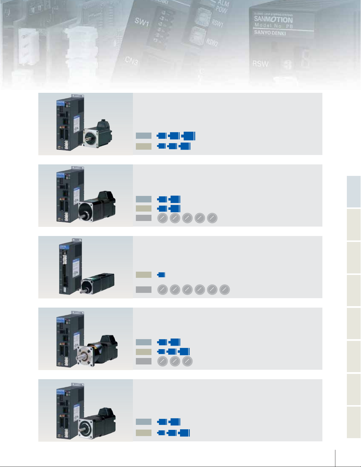
Extensive Closed-Loop Stepping System Lineup
CLOSED LOOP STEPPING SYSTEMS
How do you want to control the equipment?
The Model No. PB Series offers 3 types of control methods.
Point Command
Control using PLC I/O
Network Control using Serial
Communication (RS-485)
Power Source
AC Power Source DC Power Source
Model No.PB
Control using a Pulse
Generator
Power Source
DC Power
Source
AC Power
Source
AC Power Source
Type R
Startup via I/O
●
Startup preset points or programs
in the amplifier me mory using
the I/O.
Startup via Serial
●
Communication
Control by transmitting speed,
acceleration/deceleration and
distance data via serial
communication.
DC Power Source
Type R Multi-Axis
Startup via I/O
●
Startup preset points or programs
in the amplifier me mory using
the I/O.
Startup via Serial
●
Communication
Control by transmitting speed,
acceleration/deceleration and
distance data via serial
communication.
DC Power Source
Ty p e M
Startup via I/O
●
Startup preset points or programs
in the amplifier me mory using
the I/O.
Startup via Serial
●
Communication
Control by transmitting speed,
acceleration/deceleration and
distance data via serial
communication.
Motion is generated
●
by responding to pulse
input commands from an
upper-level controller.
AC Power Source
Type P
Motion is generated
●
by responding to pulse
input commands from an
upper-level controller.
3
Standard Model
The standard model includes an amplifier and a motor
Motor Flange Size
□
AC
DC
□
42
(1.65in)
□
28
(1.10in)
□
60
86
(2.36in)
(3.39in)
R
□
(1.65in)
□
42
60
(2.36in)
P23
Low-backlash Gear Model
This model includes a low-backlash gear that engages the final stage with a tapered gear.
Motor Flange Size
□
□
42
AC
DC
REDUCTION
GEAR
RATIO
(1.65in)
□
(1.65in)
1
42
3.6
60
(2.36in)
R
□
(2.36in)
P25
60
1
1
1
7. 2
10
1
20
30
Spur Gear Model
This model utilizes a spur gear design for gear reduction.
Functions
Features and
Typ e RTyp e PTyp e MType R Multi-Axis
Motor Flange Size
DC
REDUCTION
GEAR
RATIO
R
P29
1
1
1
1
1
3.6
7. 2
10
20
1
30
50
□
28
(1.10in)
Harmonic Gear Model
The harmonic gear provides high torque and eliminates backlash.
Motor Flange Size
□
□
42
AC
DC
REDUCTION
GEAR
RATIO
60
in
)
(1.65
(2.36in)
□
□
28
42
in
)
(1.10
(1.65in)
1
1
30
R
P31
□
60
in
(2.36
)
1
50
100
Electromagnetic Brake Model
This model uses a non-excitation electromagnetic brake, capable of maintaining
positionand supporting a load in vertical operation, even when power is off
Motor Flange Size
AC
DC
□
(1.65
□
(1.10in)
□
42
60
in
)
in
)
(2.36
□
28
42
(1.65in)
R
□
(2.36
P33
60
in
)
General
Specifications
Drawings
Motor Dimensional
Options
4
5
Model Nomenclature
`
System Model Nomenclature
Note 1: No symbol indicates no options.
Note 2: Power(39.37inch) and I/O (39.37inch) cables are included in the set models.
Motor Option 3: Holding Brake (B: included)
Note
1
Motor Option 2: Gear Ratio
Note
1
Motor Option 1: Gear Specifications
Note
1
Motor Length
Motor Flange Size (in mm)
Interface Type R: RS-485+PIO P: Pulse Stream M: Multi
Power Input A: AC Power Source D: DC Power Source
System Name PB: Model No.PB System
PB A R 60 3-C 3.6 B
`
Amplifier Model Nomenclature
Specification Identification 00: Standard
Encoder Type 1: 200P/R INC 2:500P/R INC
Interface Type R: RS-485+PIO P: Pulse Stream M: Multi
Motor Excitation Current 001: 1A 002: 2A 003: 3A
Power Input A: AC Power Source D: DC Power Source
Series Name PB□: Model No.PB Amplifier
PB3 D 003 R 1 00
`
Motor Model Nomenclature
PBM 42 3 F X E 20
DC (Multi-axis)
only
Specification Identification 20: Standard
Encoder Type
E
: 500P/R with C-phase output
A
: 200P/R No C-phase output
C
: 200P/R with C-phase output
Options
*
Contact us for assistance
X : without option
C : 24V DC Break
GA to GL : with Gear
HJ to HM : with Harmonic Gear
Power Input F: AC Power Source
,
DC Power Source
(Single-axis)
D: DC Power Source (Multi-axis)
Motor Length
Motor Flange Size (in mm)
Series Name PBM: Model No.PB Motor
Please enquire separately for the sizes of PBM503 and PBM565.
*
Motor Option CombinationTable
Motor Option Combination Table
Motor No. Gear Box Harmonic Gear
PBM
PBM
PBM
PBM
PBM
282
F□E20/PBM
284
F□E20/PBM
423
F□E20/PBM
603
F□E20/PBM
604
F□E20/PBM
282
284
423
603
604
D□A
D□A
D□A
D□A
D□A
20
20
20
20
20
○○△
××△
○○○
○○○
××○
Electromagnetic Brake
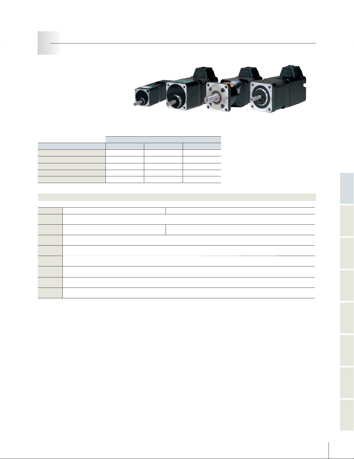
Motor Standard Specifications (common to all models)
Motor No.
Insulation
class
Withstand
Voltage
Insulation
resistance
Degrees of
protection
Vibration
resistance
Impact
resistance
Ambient
temperature
Ambient
humidity
*
*
*
The user should not test the insulation resistance or insulation withstand voltage, because a
capacitor has been inserted between the encoder output groundline and the frame to prevent noise.
PBM
423
603
F, P B M
AC1500V 50/60Hz 1minute AC500V 50/60Hz 1minute
604
F, P B M
15G(Frequency range 10 to 70Hz amplitude 0.060inch 70 to 2000 acceleration 15G)
The x, y and z are each tested three times for each direction for a total of 18 tests.
F, P B M
861
862
F, PBM
-10℃ to+ 40℃(Harmonic Gear Model 0℃to+ 40
FPBM
30G(half sine wave with 11 ms duration)
20 to 90%RH(No Condensation
282
D, PBM
Class B(130
DC500V 100M1MIN.
40
IP
℃)
282
F, P B M
Functions
Features and
284
)
D, PBM
℃)
284
F, P B M
423
D, PBM
603
D, PBM
604
D
Type RType PType MType R Multi-Axis
General
Specifications
6
Drawings
Motor Dimensional
Options
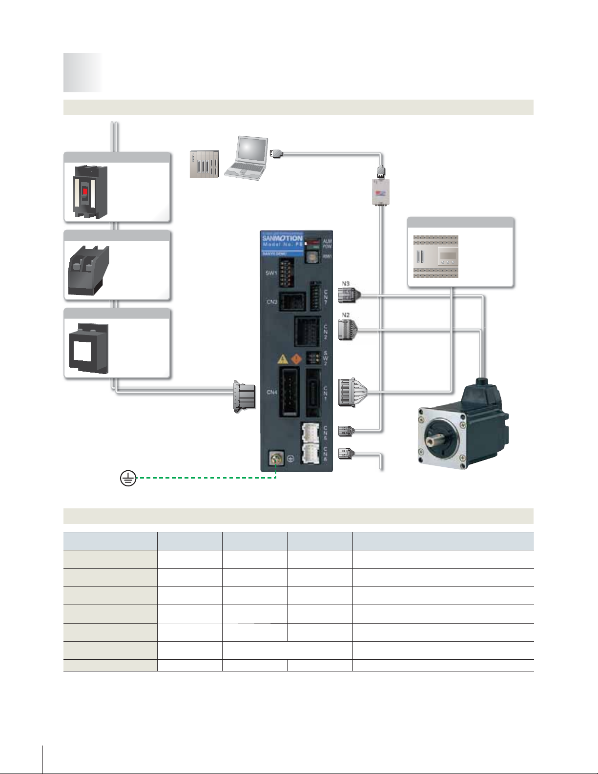
Model No. PBType R Single-Axis Type
AC Power Input Type
System Configuration
Serial communication control
Single-phase AC100V to 230V
Circuit Breaker
parameter editing
Protects the power
line; shuts off circuit
during an overflow
of electric current.
Electromagnetic Contactor
Switches amplifier
power on and off.
Installation of a
surge protector is
required.
Noise Filter
Protects the power
line from external
noise, and from
noise generated by
the servo amplifie
Power Cable
①
Controller
PC
PC I/F Software
⑦
CN4
Communication
⑥
Converter Unit
CN3
CN2
CN1
CN5
CN6
A converter unit is required for
*
RS-232C/RS-485 conversion.
Motor Ext. Cable
②
Encoder Ext. Cable
③
I/O Cable
④
Communication Cable
⑤
Control Device
PLC
SANYO DENKI's
high level
devices permit
communication
with third-party
products
Options
Cable Type
Power Cable
①
Motor Ext. Cable
②
Encoder Ext. Cable
③
I/O Cable (unshielded)
④
Communication Cable
⑤
Communication Converter Unit
⑥
PC I/F Software
⑦
7
Standard Model
Number(Length
PBC7P0010A
1m(39.37in
PBC6M0030A
3m(118.11in
PBC6E0030A
3m(118.11in
PBC1S0010A
1m(39.37in
PBC6C0003A
30cm(11.81in
PBFM-U5
SPBA1W-01
Connector Set Model
)
)
)
)
)
)
Number
PBC7P0000A
PBC6M0000A
PBC6E0000A
PBC1S0000A
PBC6C0000A
Main Body Model.No:232485CFP01-01
Cable Model.No:PBC4T0005A
−−
To other slaves
Maximum Length Remarks
2m(78.74 in
20m(787.40 in
20m(787.40 in
2m(78.74 in
100m(3937.01 in
)−
Use when an extension of 50cm(19.69in) or more is required.
)
Use when an extension of 50cm(19.69in) or more is required.
)
)−
Use when multiple axes are connected in a daisy-chain
)
configuration for communication.
RS-232C/RS-485 Converter Unit
Converter unit and cable set model
Software for operational check and parameter setting
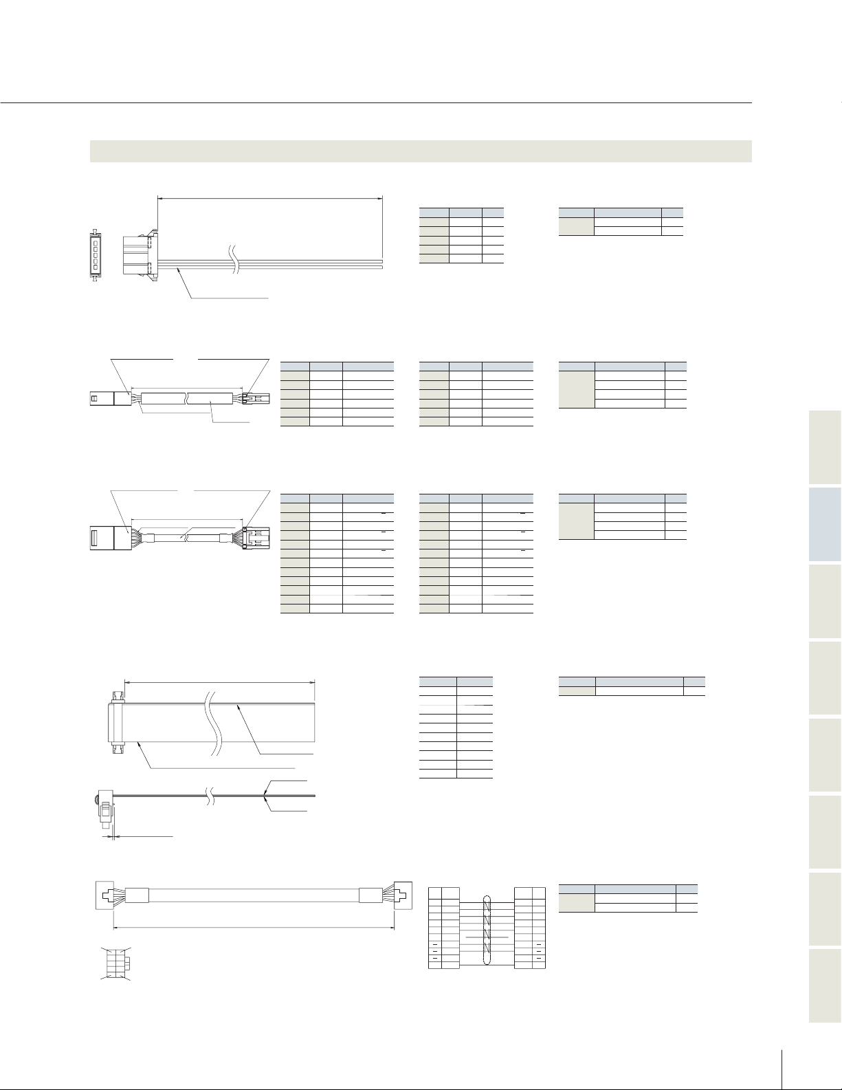
Optional Cable
①
Power Cable
Amp.side
12 34 5
②
Motor Ext. Cable
MOTOR SIDE CONNECTOR
③
Encoder Ext. Cable
MOTOR SIDE CONNECTOR
1318115-3
HOUSING:1-
1318109-1
TERMINAL:
MANUFACTURER: AMP
3000±50
LEADWIRE UL
1318115-6
HOUSING:1-
1318110-1
TERMINAL:
MANUFACTURER:AMP
3000±50
LEADWIRE AWG
AWG16 Black UL1015
AMPLIFIER SIDE CONNECTOR
HOUSING:1TERMINAL:
MANUFACTURER: AMP
118.11±1.97
mm (
1430
22
AWG
ULVINYL TUBE
AMPLIFIER SIDE CONNECTOR
HOUSING:1-
TERMINAL:
MANUFACTURER:AMP
118.11±1.97
mm (
in)
28
ENCODER CABLE
20276
UL
in)
1318106-1
±
L
1318119-3
1318105-1
1318118-6
±
50
1.97
mm (L
Connector Connection Of Motor Side
PIN No.
A1Blue
B1Orange
A2Red
B2Yellow
A3White Brake Lead Wire
B3Black Brake Lead Wire
Connector Connection Of Motor Side
PIN No.
A1Blue CHANNEL A
B1Brown
A2Green CHANNEL B
B2Purple
A3White CHANNEL C
B3Yellow
A4Red +5V
B4Black
A5N.C.
B5Orange OVER HEAT
A6Black Shield
B6N.C.
in)
LEAD COLR
LEAD COLR
Motor Lead Wire
Motor Lead Wire
Motor Lead Wire
Motor Lead Wire
CHANNEL A
CHANNEL B
CHANNEL C
0
V
―
―
PIN No.
LEAD COLR
1
2
3
4
Power
Supply
5
Connector Connection Of Amplifier Side
PIN No.
LEAD COLR
1(A1
) Blue
2(B1
) Orange
3(A2
)Red
4(B2
)Yellow
5(A3
) White Brake LeadWire
6(B3
) Black Brake Lead Wire
Connector Connection Of Amplifier Side
PIN No.
LEAD COLR
1(A1
) Blue CHANNEL A
2(B1
)Brown
3(A2
) Green CHANNEL B
4(B2
) Purple
5(A3
) White CHANNEL C
6(B3
)Yellow
7(A4
)Red +5V
8(B4
)Black0V
9(A5
) N.C.
10(B5
) Orange OVER HEAT
11(A6
)Black Shield
12(B6
) N.C.
1
Black AC
2
Black AC
――
――
――
Motor Lead Wire
Motor Lead Wire
Motor Lead Wire
Motor Lead Wire
CHANNEL A
CHANNEL B
CHANNEL C
Connector Set : PBC7P
Manufacturer
AMP
Connector Set : PBC6M
Manufacturer
AMP
Connector Set : PBC6E
Manufacturer
AMP
―
―
0000
Typ e Qt y.
Housing :1-
175218-55
Contact :1-
0000
Typ e Qt y
Housing :1-
:
1318109-16
Ter m i na l
Housing :1-
:
1318105-16
Ter m i na l
0000
Typ e Qt y
Housing :1-
:
1318110-110
Ter m i na l
Housing :1Ter m i na l :1-
A
178288-51
A
1318115-31
1318119-31
A
1318115-61
1318118-61
1318106-110
Functions
Features and
Typ e RTyp e PTyp e MType R Multi-Axis
④
I/O Cable (unshielded)
1
B
E
1
A
10
A
10
B
Flat cable UL
1
mm MAX.
039
.
inch MAX.
⑤
Communication Cable
9
1
10
9
2
1
2962
±
L
L
AWG
30
28
mm (L
Cable Mark
Cable
Cable
±
1.18
in)
CONNECTOR
0000
A
Typ e Qt y
:
8822E-020-171D1
Cable Connection
Cable1Cable
A1-No.1B1-No.
A2-No.2B2-No.
A3-No.3B3-No.
A4-No.4B4-No.
A5-No.5B5-No.
A6-No.6B6-No.
A7-No.7B7-No.
A8-No.8B8-No.
A9-No.9B9-No.
1
A10-No.10B10-No.
2
11
12
13
14
15
16
17
18
19
20
Connector Set : PBC1S
Manufacturer
KEL
2
General
Specifications
Housing
Contact
0000
A
Typ e Q ty
:
PAD P-10V-1-S
:
SPH-OO2T- P0.5L
2
20
Drawings
Motor Dimensional
Connector relay cable
1
CNA
Signal
Name
Pin.No.
A
1
9
B
2
(Y)
3
)
(
Z
4
GND
5
Vcc
6
7
8
9
FG
10
Yellow
White
Brown
Blue
Black
Purple
Green
Drain
Connector Set : PBC6C
CNB
Pin.No.
Yellow
White
Brown
Blue
Black
Red
Red
Purple
Green
Drain
Manufacturer
Signal
Name
A
1
2
3
4
5
6
7
8
9
10
(Y)
(
GND
JST
B
)
Z
Vcc
FG
Options
8
9
General Specifications
Model No. PBType R Single-Axis Type
AC Power Input Type
Amplifier Model
PB3A
003R200
Control Mode PWM Control SIN drive method
Power Supply
Single Power AC100V to 230V −15% +10% 50/60Hz
Environment
Ambient
temp.
Operating
0 to 55
℃
Storage −20 to 70
℃
Operating/
Storage Humidity
Maximum 90% RH(non-condensing
)
Vibration Resistance
0.5G(tested with frequency range 10 to 55 Hz, X, Y, Z each direction 2H
)
Structure Tray structure Rear mounting type
Mass
(
Weight)/ Dimensions Approx. 0.8kg(28.22oz
)
/
W45×H150×D120mm(W1.77×H5.91×D4.72inch
)
Functions
Rotation Speed 0 to 4500min
-1
(
4000min
-1
is used for an 86mm-square motor
)
Resolution
(
P/R)500, 1000, 2000, 4000, 5000, 10000
Regeneration Process
Internal(external regeneration available
)
Protective Functions
Encoder Disconnection, Encoder Counter Error, Power Voltage Error, Initialization Error, Position Deviation Error, Over-speed,
Regeneration Voltage Error, Zero-return Error, Absolute position sign reversal, Deviation Counter Overflow, Motor Overheat,
Amplifier Overheat, Internal voltage Error, Over-current, CPU Error
LED Display Power status, Alarm(flashing indicator
)
Operation Functions
Normal Drive(incremental move command, absolute move command), Zero-return, Module Operation, Push Operation
Switch
DIP SW1: Transmission Speed Setting(9600, 38400,115200,128000bps) DIP SW2: Terminating Resistor Setting
RSW:Node Adress Setting(0 to F
)
Input/
Output
Signals
Input Signals
Fixed function(2): EXE
,
Point,ALMCLR,STOP
Selectable(5): Point
,
Pause,Interlock,SELECT,Generic Input,HOME,Hard Limit
Output Signals
CN1 Fixed function(2): ALM, In-Position, Ack
Selectable(5): ZONE, END, Busy, HEND, SON MON, Generic Input, Input Monitor
Communication
Specifications
RS-485 Standard Start-Stop Synchronization, Full Duplex
Trans. Speed
:
9600,38400,115200,128000bps
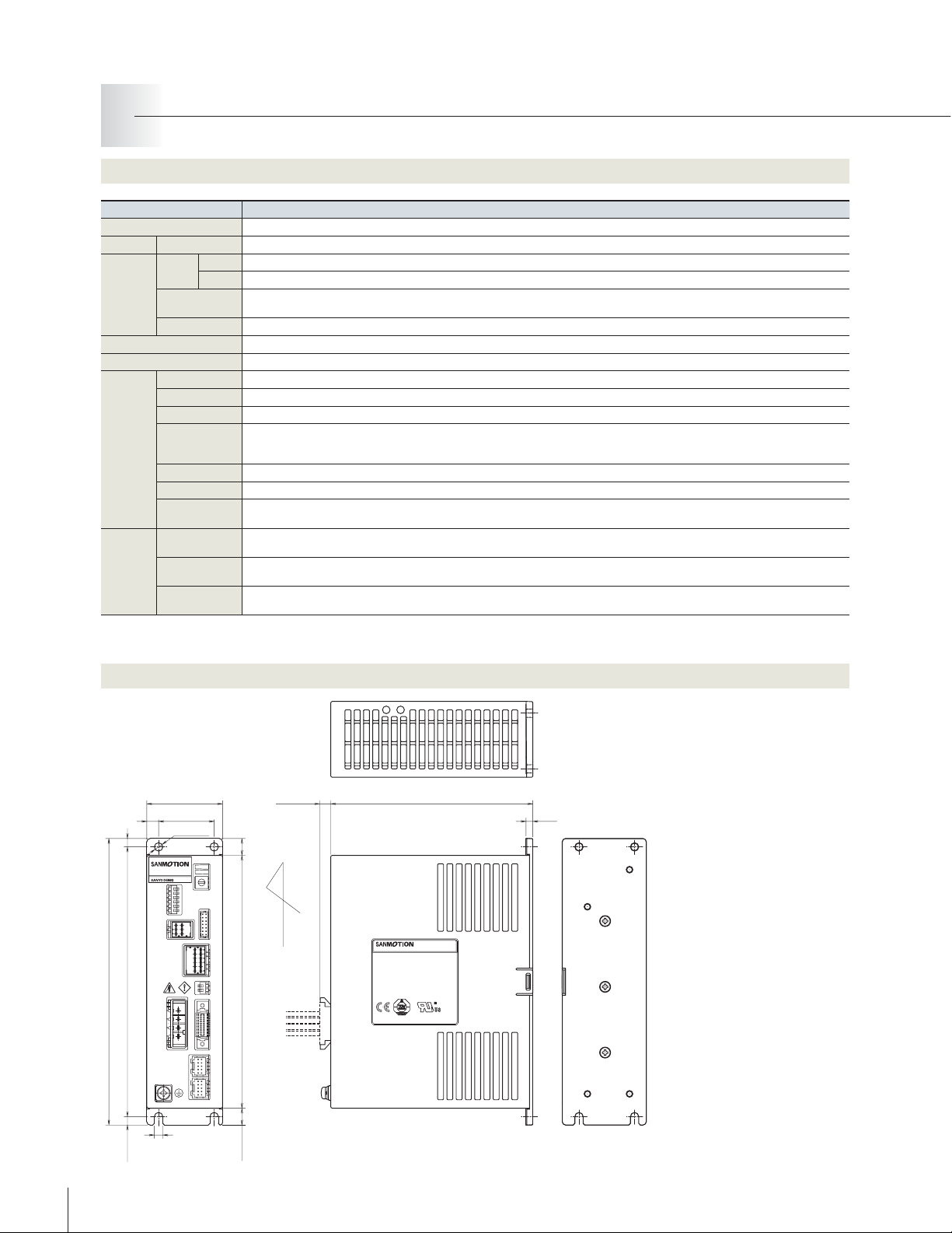
Amplifier Dimensional Drawing[Unit : mm (inch
)]
Mounting Direction
10(.39)
150(5.91)
6.5(.26)
CLOSED LOOP STEPPING SYSTEMS
MADE IN JAPAN
170(6.69)
5(.20)
160(6.30)
7(.28)
CLOSED LOOP STEPPING SYSTEMS
ModelNo.PB
SW1
CN3
CN4
45(1.77)
33(1.30)
2-φ5(2-φ.20)
ALM
POW
D
E
C
F
0
B
1
A
9
2
RSW1
8
3
7
4
5
6
C
N
7
C
N
2
S
W
2
C
N
1
C
N
5
C
N
6
120(4.72)
4(.16)
ModelNo.PB
00563491
5(.20)
5(.20)
10(.39)

External Wiring Diagram
Input Power
100
AC
+COM(DC
4
IN
or SDN(Point6)
OUT
User Device
230
Vto
GND
N.C
N.C
N.C
N.C
5
Vto24V)
Point
Point
IN1(Point3)
2
IN
(Point4)
3
IN
(Point5)
ALMCLR
5
IN
(Point7)
In-Position
1
OUT
(ZONE)
2
OUT
(END)
3
(SON MON)
−
V
Exe
STOP
ACK
ALM
OUT
OUT
COM
Amplifier
003R200
PB3A
4
CN
5
1
2
N.C
N.C
1
2
4
5
3
4
6
CN5,
1
2
Vcc
3
4
5
GND
5
V
+
6
7
8
9
10
1
CN
1
3
4
5
6
7
8
9
10
11
12
13
14
15
16
17
18
19
20
2
P. E ( M4)
CN
CN
BRK+
BRK-
CN
N.C
O.H
N.C
2
1
A
2
A
3
B
4
B
5
C
6
C
7
5
V
8
5
G
9
10
11
FG
12
3
1
A
2
A
3
B
4
B
5
6
7
Holding Brake
24VDC
(
)
)
*
OPTICAL
ENCORDER
TH
Motor
Twisted Pair
Cable With External Shield
Functions
Features and
Typ e RTyp e PType MType R Multi-Axis
Input / Output Signals Circuit
Generic Input
■
Input Voltage Specifications : DC5V to 24V±10
+COM
1
DC Power Source
+5Vto24V
Note 1: The CN1 general-purpose input / output signal function is selected through communication.
Please see the basic specifications for details.
Generic Output
■
%
Output Current : 30mA MAX.
MAX.
30
V
2
−
COM
-COM
MAX.
General
30
mA
Specifications
Drawings
SG
Motor Dimensional
Options
10

Model No. PBType P
AC Power Input Type
System Configuration
Single-phase AC100V to 230V
Circuit Breaker
Protects the power
line; shuts off circuit
during an overflow
of electric current.
Electromagnetic Contactor
Switches amplifier
power on and off.
Installation of a
surge protector is
required.
Noise Filter
Protects the power
line from external
noise, and from
noise generated by
the servo amplifier.
Power Cable
①
parameter editing
PC I/F Software
⑦
4
CN
PC
3
CN
CN
CN
2
1
Motor Ext. Cable
②
Encoder Ext. Cable
③
I/O Cable
④
Control Device
PLC/Pulse board Controller
SANYO DENKI's high level devices permit
communication with third-party products.
Options
Cable Type
Power Cable
①
Motor Ext. Cable
②
Encoder Ext. Cable
③
I/O Cable (shielded)
④
Communication Cable
⑤
(Dsub9pin)
Communication
⑥
Converter Unit
PC I/F Software
⑦
Standard Model
Number(Length
PBC7P0010A
1m(39.37in
PBC6M0030A
3m(118.11in
PBC6E0030A
3m(118.11in
PBC1S0010C
1m(39.37in
PBC5C0010A
1m(39.37in
Not required
SPBA1W-01
)
)
)
)
)
)
5
CN
Communication Cable
⑤
Connector Set
Model Number
PBC7P0000A
PBC6M0000A
PBC6E0000A
PBC1S0000A
−−
−− −
−−
Maximum Length Remarks
2m(78.74 in
20m(787.40 in
20m(787.40 in
2m(78.74 in
)−
Use when an extension of 50cm(19.69in
)
or more is required.
Use when an extension of 50cm(19.69in
)
or more is required.
)−
Dedicated cable for RS-232C
communications
Software for operational check and
parameter setting
)
)
11

Optional Cable
①
Power Cable
Amp.side
12 34 5
②
Motor Ext. Cable
MOTOR SIDE CONNECTOR
③
Encoder Ext. Cable
MOTOR SIDE CONNECTOR
1318115-3
HOUSING:1-
1318109-1
TERMINAL:
MANUFACTURER: AMP
3000±50
LEADWIRE UL
1318115-6
HOUSING:1-
1318110-1
TERMINAL:
MANUFACTURER:AMP
3000±50
LEADWIRE AWG
AWG16
AMPLIFIER SIDE CONNECTOR
HOUSING:1TERMINAL:
MANUFACTURER: AMP
118.11±1.97
mm (
1430
22
AWG
AMPLIFIER SIDE CONNECTOR
HOUSING:1-
TERMINAL:
MANUFACTURER:AMP
118.11±1.97
mm (
28
ENCODER CABLE
20276
UL
±
L
Black
1318119-3
1318105-1
in)
ULVINYL TUBE
1318118-6
1318106-1
in)
50
mm (L
UL1015
±
1.97
in)
Connector Connection Of Motor Side
PIN No.
LEAD COLR
Blue Motor Lead Wire
1
A
Orange Motor Lead Wire
1
B
Red Motor Lead Wire
2
A
Yellow Motor Lead Wire
2
B
White Brake Lead Wire
3
A
Black Brake Lead Wire
3
B
Connector Connection Of Motor Side
LEAD COLR
PIN No.
A1Blue CHANNEL A
B1Brown
A2Green CHANNEL B
B2Purple
A3White CHANNEL C
B3Yellow
A4Red +5V
B4Black
A5N.C.
B5Orange OVER HEAT
A6Black Shield
B6N.C.
Power
Supply
CHANNEL A
CHANNEL B
CHANNEL C
0
V
―
―
PIN No.
LEAD COLR
1
2
3
4
5
Connector Connection Of Amplifier Side
PIN No.
LEAD COLR
1(A1
)Blue
2(B1
) Orange
3(A2
)Red
4(B2
)Yellow
5(A3
)WhiteBrakeLeadWire
6(B3
)BlackBrakeLeadWire
Connector Connection Of Amplifier Side
PIN No.
LEAD COLR
1(A1
) Blue CHANNEL A
2(B1
)Brown
3(A2
)Green CHANNELB
4(B2
) Purple
5(A3
)White CHANNELC
6(B3
)Yellow
7(A4
)Red +5V
8(B4
)Black0V
9(A5
) N.C.
10(B5
) Orange OVER HEAT
11(A6
) Black Shield
12(B6
) N.C.
1
Black AC
2
Black AC
――
――
――
Motor Lead Wire
Motor Lead Wire
Motor Lead Wire
Motor Lead Wire
CHANNEL A
CHANNEL B
CHANNEL C
―
―
Connector Set : PBC7P
Manufacturer
Housing
AMP
Contact
Connector Set : PBC6M
Manufacturer
Housing :1Ter m i na l
AMP
Housing :1Ter m i na l
Connector Set : PBC6E
Manufacturer
Housing
Ter m i na l
AMP
Housing
Ter m i na l :1-
0000
A
Typ e Q t y.
:
1-178288-51
:
1-175218-55
0000
A
Typ e Qt y.
1318115-31
:
1318109-16
1318119-31
:
1318105-16
0000
A
Typ e Qty .
:
1-1318115-61
:
1318110-110
:
1-1318118-61
1318106-110
Functions
Features and
Typ e RTyp e PType MType R Multi-Axis
④
I/O Cable (shielded)
±
L
1
B
A1g
10
B
10
A
⑤
Communication Cable (Dsub 9Pin)
mm
10
±
150
in)
39
.
±
91
.
5
(
PC side
95
61
50
mm (L
±
1.97
±
50
L
in)
mm (L
CN1 Wiring
CN1 PIN No.
1
A
2
A
3
A
4
A
5
A
6
A
7
A
8
A
9
A
10
A
Mark
Display
|
Mark
Red
Black
Red
Black
Red
Black
Red
Black
Red
Black
LINE
COLR
Orange
Gray
White
Yel lo w
Pink
CN1 PIN No.
1
B
2
B
3
B
4
B
5
B
6
B
7
B
8
B
9
B
10
B
Mark
Display
|
|
Mark
Red
Black
Red
Black
Red
Black
Red
Black
Red
Black
LINE
COLR
Orange
Gray
White
Yel lo w
Pink
Connector Set : PBC1S
Manufacturer
KEL
0000
:
Connector
Crimp Contact
Drain Wire:UL
20276-28
Cable:UL
A
Typ e Qt y.
8822E-020-171D1
:
4
V1.25-M
1007 20
AWG
AWG
―
―
―
General
±
1.97
in)
Amp.side
192
Connector relay cable
PC Side
Signal
Pin.No.
Name
N.C
1
RXD
2
TXD
3
N.C
4
GND
5
N.C
6
N.C
7
N.C
8
N.C
9
(RS-232C D-Sub 9Pin)
Amp.Side
Pin.No
Signal
Name
RXD
1
TXD
2
N.C
3
N.C
4
GND
5
N.C
6
N.C
7
N.C
8
N.C
9
Shield
10
Without connector set
*
Specifications
Drawings
Motor Dimensional
Options
12

13
Model No. PBType P
AC Power Input Type
General Specifications
Amplifier Dimensional Drawing[Unit : mm (inch
)]
Amplifier Model
PB3A
003P201
,PB3A
003P202
Control Mode PWM Control SIN drive method
Power Supply
Single Power AC100V to 230V −15% +10% 50/60Hz
Environment
Ambient temp.
Operating
0 to 55
℃
Storage −20 to 70
℃
Operating/
Storage Humidity
Maximum 90% RH(non-condensing
)
Vibration Resistance 0.5G(tested with frequency range 10 to 55 Hz, X, Y, Z each direction 2H
)
Structure Tray structure Rear mounting type
Mass
(
Weight)/ Dimensions Approx. 0.8kg(28.22oz
)
/
W45×H150×D120mm(W1.77×H5.91×D4.72inch
)
Functions
Rotation Speed 0 to 4500min
-1
(
4000min
-1
is used for an 86mm-square motor
)
Resolution (P/R) 500, 1000, 2000, 4000, 5000, 10000
Regeneration Process Internal(external regeneration available
)
Protective Functions
Encoder Disconnection, Encoder Counter Error, Power Voltage Error, Initialization Error, Position Deviation Error,
Over-speed,Regeneration Voltage Error, Zero-return Error, Absolute position sign reversal, Deviation Counter Overflow,
Motor Overheat, Amplifier Overheat, Internal voltage Error, Over-current, CPU Error
LED Display Power status, Alarm (flashing indicator
)
Functions Normal Drive, Zero-return, S-shape Acceleration / Deceleration Drive
Switch
DIP SW1: Pulse Input Type Select (ON: 2 Input OFF: 1 Input
)
DIP SW2, 3: Resolution Selection(500, 1000, 5000, 10000P/R
)
※
2000 and 4000 division resolution modes are selected via communication
DIP SW 4 to 6: Motor Select
RSW1: Normalize velocity loop gain setting
RSW2: S-Shape filter potentiometer setting
Input/ Output
Signals
Input Signals Pulse, Deviation Clear, HOME, Hard.Limit, STOP, ALMCLR
Output Signals SON Monitor, ALM, Zero-return completion,In-Position, Encoder Signal Output
Communication
Specifications
RS-232C(For parameter setting
)
Trans. Speed:9600bps
170(6.69)
5(.20)
160(6.30)
7(.28)
CLOSED LOOP STEPPING SYSTEMS
ModelNo.PB
SW1
CN3
CN4
45(1.77)
33(1.30)
2-φ5(2-φ.20)
10(.39)
ALM
POW
D
C
E
B
F
A
0
9
1
8
RSW1
2
7
3
6
4
5
D
C
E
B
F
A
0
9
1
8
RSW2
2
7
3
6
4
5
C
N
7
C
N
2
150(5.91)
C
N
1
C
N
6
C
N
5
6.5(.26)
Mounting Direction
CLOSED LOOP STEPPING SYSTEMS
120(4.72)
4(.16)
ModelNo.PB
MADE IN JAPAN 00563491
5(.20)
5(.20)
10(.39)

External Wiring Diagram
User Device
Input Power
100
230
AC
Vto
N.C
TXD
RXD
NC
NC
GND
NC
NC
NC
NC
CCW Pulse+ /Pulse+
CCW Pulse- /Pulse-
CW Pulse+ /DIR+
CW Pulse- /DIR-
-COM
5
Vto24V)
+COM(DC
STOP
ALMCLR
(Deviation Clear)
1
IN
IN2(Gain Select)
Im-Position
SON Monitor
ENA+
ENA-
ENB+
ENBENC+
ENC-
-COM
Amplifier
3A003P201
PB
4
CN
N.C
V
5
1
1
AC
2
2
AC
3
P
4
N
5
CN
1
2
3
4
5
GND
Vcc
6
7
8
9
10
1
CN
3
4
5
6
14
1
7
8
9
10
11
12
13
15
16
17
18
19
20
2
P.E(M4)
2
CN
1
A
2
A
3
B
4
B
5
C
6
C
7
5
V
8
5
G
10
OH
11
FG
3
CN
1
A
2
A
3
B
4
B
5
BRK+
6
BRK-
Holding
Brake
24VDC
(
)
)
*
7
CN
6
CN
1
2
Positive direction Limit (SDN)
3
4
Negative direction Limit(SDN)
5
Without allocation function
6
7
Without allocation function
8
9
NC
10
NC
OPTICAL
ENCORDER
EN
MO
BRK
Motor
Twisted Pair Cable
With External Shield
Note 1: The CN1 general-purpose input/output signal function is
selected through communication. Please see the basic
specifications for details.
Note 2: Pulse input and encoder output signal circuitry are line
receiver type.Linedriver type is also available as amplifier
model PB3A003P202.
Functions
Features and
Typ e RType PType MType R Multi-Axis
Input / Output Signals Circuit
,
3,5
6
MAX.
30
V
-COM
)/(
MAX.
270
30
mA
+R)≒
003P201
PB3A
Pulse Input
■
Input Voltage Specifications : DC5V±10
DC Power Source
4
In case the voltage is at 5V MIN.
Insert a resistor "R" which satisfies "
Input Voltage−1V
(
Line driver input permitted
Encoder Signal Output
■
Collector Voltage: DC30V MAX.
Output Current : 30mA MAX.
15、17、19
2、14、16、18、20
10 mA
003P201/202
003P202
PB3A
Pulse Input
■
%
Pulse Input : 250kpps MAX.
3,5
4
6
,
14
SG
SG
+5V+5V
SG
PB3A
Generic Input/Limit Input
■
Input Voltage Specifications : DC5V to 24V±10
DC Power Source
+5Vto24V
%
General
Encoder Signal Output
■
15,17,19
20
16
,18,
14
SG
Generic Output
■
Collector Voltage: DC30V MAX.
Output Current : 30mA MAX.
30
MAX.
MAX.
30
V
2
-COM
mA
-COM
Specifications
Drawings
Motor Dimensional
Options
14

Model No. PBType M
DC Power Input Type
System Configuration
Circuit Breaker
Protects the power
line; shuts off circuit
during an overflow
of electric current.
Electromagnetic Contactor
Switches amplifier
power on and off.
Installation of a
surge protector is
required.
Noise Filter
Protects the
power line from
external noise,
and from noise
generated by the
servo amplifier.
Power Supply Switch
Converts power
supply from AC
to DC power.
Serial communication control
parameter editing
Controller PC
PC I/F Software
⑦
4
CN
Communication
⑥
Converter Unit
6
CN
5
CN
1
CN
④
2
CN
③
3
CN
②
*
RS-232C/RS-485 conversion.
⑤
I/O Cable
Encoder Ext. Cable
Motor Ext. Cable
A converter unit is required for
Communication Cable
Control Device
PLC I/O
To other slaves
SANYO DENKI's
high level
devices permit
communication
with third-party
products
Options
Cable Type
Power Cable
①
Motor Ext. Cable
②
Encoder Ext. Cable
③
I/O Cable (unshielded)
④
I/O Cable (shielded)
④
Communication Cable (to
⑤
Communication Converter Unit
⑥
PC I/F Software
⑦
Amp.
Power Cable
①
Standard Model
Number(Length
PBC6P0010A
1m(39.37in
PBC6M0030A
3m(118.11in
PBC6E0030A
3m(118.11in
PBC5S0010A
1m(39.37in
PBC5S0010C
1m(39.37in
PBC6C0003A
)
30cm(11.81in
PBFM-U5
SPBAIW01
Connector Set Model
)
)
)
)
)
)
)
Number
PBC6P0000A
PBC6M0000A
PBC6E0000A
PBC5S0000A
PBC5S0000A
PBC6C0000A
Main Body Model.No:232485CFP01-01
Cable Model.No:PBC4T0005A
−−
Maximum Length Remarks
2m(78.74 in
20m(787.40 in
20m(787.40 in
2m(78.74 in
2m(78.74 in
100m(3937.01 in
)−
Use when an extension of 50cm(19.69in) or more is required.
)
Use when an extension of 50cm(19.69in) or more is required.
)
)−
Use for pulse input
)
Use when multiple axes are connected in a daisy-chain
)
configuration for communication.
RS-232C/RS-485 Converter Unit
Converter unit and cable set model
Software for operational check and parameter setting
15

Optional Cable
①
Power Cable
±
L
50
mm (L
±
1.97
in)
1234
②
Motor Ext. Cable
MOTOR SIDE CONNECTOR
③
Encoder Ext. Cable
MOTOR SIDE CONNECTOR
④
I/O Cable (unshielded)
1318115-3
HOUSING:1-
1318109-1
TERMINAL:
MANUFACTURER: AMP
3000
LEADWIRE UL
1318115-6
HOUSING:1-
1318110-1
TERMINAL:
MANUFACTURER:AMP
3000±50
LEADWIRE AWG
±
50
118.11±1.97
mm (
1430
AWG
118.11±1.97
mm (
28
AMPLIFIER SIDE CONNECTOR
1318119-3
HOUSING:1-
1318105-1
TERMINAL:
MANUFACTURER: AMP
in)
22
ULVINYL TUBE
AMPLIFIER SIDE CONNECTOR
1318118-6
HOUSING:1-
1318106-1
TERMINAL:
MANUFACTURER:AMP
in)
ENCODER CABLE
20276
UL
L
1
B
E
1
A
13
A
13
B
Flat cable UL
1
mm MAX.
039
.
inch MAX.
④
I/O Cable (shielded)
1
B
E
1
A
13
B
13
A
mm
10
±
150
⑤
Communication Cable (Dsub 9 Pin)
2962
AWG
±
L
in)
39
.
±
91
.
5
(
50
mm (L
±
1.97
9
1
±
30
mm (L
L
10
9
2
1
1430
UL
300V,105
Cable Mark
28
in)
±
AWG18(21/0.18)
℃
Connector Connection Of Motor Side
PIN No.
1
A
1
B
2
A
2
B
3
A
3
B
Connector Connection Of Motor Side
PIN No.
1
A
1
B
2
A
2
B
3
A
3
B
4
A
4
B
A5N.C.
5
B
6
A
B6N.C.
1
Cable
2
Cable
1.18
in)
LEAD COLR
Blue Motor Lead Wire
Orange Motor Lead Wire
Red Motor Lead Wire
Yellow Motor Lead Wire
White Brake Lead Wire
Black Brake Lead Wire
LEAD COLR
Blue
CHANNEL A
Brown
CHANNEL A
Green
CHANNEL B
Purple
CHANNEL B
White
CHANNEL C
Yellow
CHANNEL C
Red
Black
Orange
OVER HEAT
Black
CN Wiring
CN1 Pin.No.
Signal Name
1
A
2
A
3
A
4
A
5
A
6
A
7
A
8
A
9
A
10
A
11
A
12
A
13
A
+5V
0
―
Shield
―
|
|
|
Connector Connection Of Amplifier Side
PIN No.
LEAD COLR Signal Name
Red
1
2
3
4
Connector Connection Of Amplifier Side
PIN No.
1(A1
)
2(B1
)
3(A2
)
4(B2
)
5(A3
)
6(B3
)
Connector Connection Of Amplifier Side
PIN No.
1(A1
)
2(B1
)
3(A2
)
4(B2
)
5(A3
)
6(B3
)
7(A4
)
Red
Red
Red
Red
Red
Red
Red
8(B4
)
9(A5
)N.C.
10(B5
)
11(A6
)
12(B6
)N.C.
Cable Connection
Cable
A1-No.1B1-No.
A2-No.2B2-No.
A3-No.3B3-No.
A4-No.4B4-No.
A5-No.5B5-No.
A6-No.6B6-No.
A7-No.7B7-No.
A8-No.8B8-No.
A9-No.9B9-No.
A10-No.10B10-No.
A11-No.11B11-No.
A12-No.12B12-No.
A13-No.13B13-No.
LINE
CN1 Pin.No.
COLR
Orange
Gray
White
Yellow
Pink
Orange
B
B
Gray
Connector relay cable
CNA
Signal
Name
Pin.No.
A
1
B
2
(Y)
3
)
(
Z
4
GND
5
Vcc
6
7
8
9
FG
10
V
Mark
Black
Black
Black
Black
Black
Black
1
9
DC+24/48V
Blue
GND
Yellow
Green
LEAD COLR
Orange Motor Lead Wire
Yellow Motor Lead Wire
LEAD COLR
Brown
Yellow
Orange
1
1
B
2
B
3
B
4
B
5
B
6
B
7
B
8
B
9
B
10
B
11
B
12
13
Yellow
White
Brown
Blue
Black
Red
Purple
Green
Drain
―
FG
Blue Motor Lead Wire
Red Motor Lead Wire
White Brake Lead Wire
Black Brake Lead Wire
Blue
CHANNEL A
CHANNEL A
Green
CHANNEL B
Purple
CHANNEL B
White
CHANNEL C
CHANNEL C
Red
Black
OVER HEAT
Black
Cable
Signal Name
|
|
|
|
|
Yellow
White
Brown
Blue
Black
Red
Purple
Green
Drain
+5V
Shield
2
14
15
16
17
18
19
20
21
22
23
24
25
26
Pin.No.
0
―
―
CNB
V
Mark
Black
Red
Black
Red
Black
Red
Black
Red
Black
Red
Black
Red
Black
1
2
3
4
5
6
7
8
9
10
Signal
Name
(Y)
(
GND
Vcc
A
B
)
Z
FG
LINE
COLR
Gray
White
Yellow
Pink
Orange
Gray
White
Connector Set : PBC6P
Manufacturer
JST
Connector Set : PBC6M
Manufacturer
AMP
Connector Set : PBC6E
Manufacturer
AMP
Connector Set : PBC5S
Manufacturer
KEL
Connector Set : PBC5S
Manufacturer
KEL
Connector Set : PBC6C
Manufacturer
JST
0000
A
Typ e Qt y.
:
Connector
VHR-4N
:
Contact
Appropriate electric wire:AWG#22-18
Housing :1Ter m i na l
Housing :1Ter m i na l
Housing
Ter m i na l
Housing
Ter m i na l :
Connector
Connector
Crimp Contact:V1.25-M
Drain Wire:UL
Cable:UL
Housing
Contact
14
SVH-21T- P1.
0000
A
Typ e Qty .
1318115-31
:
1318109-16
1318119-31
:
1318105-16
0000
A
Typ e Qt y.
:
1-1318115-61
:
1318110-110
:
1-1318118-61
1318106-1
0000
A
Typ e Qt y.
:
8822E-026-171D1
0000
A
Typ e Qt y.
:
8822E-026-171D1
1007 20
20276-28
AWG
0000
A
Typ e Qt y.
:
PAD P-10V-1-S
:
SPH-OO2T- P0.5L
4
AWG
1
―
10
Functions
Features and
Typ e RTyp e PTyp e MType R Multi-Axis
―
―
―
General
Specifications
Drawings
2
20
Motor Dimensional
Options
16

17
Model No. PBType M
DC Power Input Type
External Wiring Diagram
Positive direction Pulse+ /Pulse+
Positive direction
Pulse- /Pulse-
-COM
+COM(+
5
Vto24VDC)
Positive direction Limit
Negative direction Limit
IN
1
(HOME)
IN
2
(
Deviation CLR
)
IN
3
(Gain SEL1)
IN
4
(Gain SEL2)
IN
5
(
Current limit
)
STOP
ALMCLR
ALM
HEND
SON MON
STOP MON
Reserved
Reserved
In-Position
ENC / Phase origin
ENA
ENB
-COM
1
2
3
4
14
25
5
6
7
8
9
10
11
12
13
15
16
17
18
19
20
21
22
23
24
26
Note 1: The CN1 general-purpose input / output signal function is selected through communication. Please see the basic specifications for details.
Holding Brake
(
24VDC
)
Motor
Twisted Pair Cable
With External Shield
CN
1
CN
3
A
A
B
B
BRK+
BRK-
1
2
3
4
5
6
CN
2
A
A
B
B
C
C
5
V
5
G
NC
NC
FG
NC
1
2
3
4
5
6
7
8
9
10
11
12
OPTICAL
ENCORDER
1
2
3
4
CN
4
Amplifier
PB3D
003M200
CN5,
6
1
2
6
5
7
10
DIP SW-
2
Vcc
User Device
Input Power
DC24V/48V
N.C
CTXD
RTXD
NC
GND
STOP
Pow
GND
GND
Terminating
resistance
CTXD
CRXD
■
Pulse Stream Input DIP Switch SW1:OFF
■
Generic Input DIP Switch SW1:ON
-COM
+COM(+
5
Vto24V)
IN
1
(EXE)/PWR
IN
2
(Point0)/Point
0
IN3(Point1)/Point
1
IN4(Point2)/Point
2
IN5(Point3)/Point
3
IN6(Point4)/Point
4
IN7(HOME)/Jog+
IN
8
(STOP)/STOP
ALMCLR/Jog-
ALM/ALM
OUT
1
(PEND0)/PEND
0
OUT2(PEND1)/PEND
1
OUT3(PEND2)/PEND
2
OUT4(PEND3)/PEND
3
OUT5(PEND4)/PEND
4
OUT6(HEND)/HEND
OUT
7
(In-Position)/In-Position
OUT
8
(MODE MON)/MODE MON
OUT
9
(SON MON)/SON MON
-COM
1
2
3
4
14
25
5
6
7
8
9
10
11
12
13
15
16
17
18
19
20
21
22
23
24
26
Holding Brake
(
24VDC
)
Motor
Twisted Pair Cable
With External Shield
CN
1
CN
3
A
A
B
B
BRK+
BRK-
1
2
3
4
5
6
CN
2
A
A
B
B
C
C
5
V
5
G
NC
NC
FG
NC
1
2
3
4
5
6
7
8
9
10
11
12
OPTICAL
ENCORDER
1
2
3
4
CN
4
Amplifier
PB3D
003M200
CN5,
6
1
2
6
5
7
10
DIP SW-
2
Vcc
User Device
Input Power
DC24V/48V
N.C
CTXD
RTXD
NC
GND
STOP
Pow
GND
GND
Terminating
resistance
CTXD
CRXD
Nomal (initial value)/ Teaching
Preliminary
Preliminary
General Specifications
Amplifier Model
PB3D
003M200
Interface Generic Input (SW1=ON
)
Pulse Train Input (SW1=OFF
)
Control Mode PWM Control SIN drive method
Power
Supply
Single Power DC24V/48V ±10%
(
□
28mm [□1.10inch] Motor is only available as 24V.
)
Ambient
temp.
Operating
0 to 55
℃
Storage
−20 to 70
℃
Operating/
Storage Humidity
Maximum 90% RH (non-condensing)
Vibration Resistance
0.5G(tested with frequency range 10 to 55 Hz, X, Y, Z each direction 2H
)
Mass(Weight)/ Dimensions
Approx. 0.36kg (12.70oz
)
/
W32×H160×D95mm(W1.26×H6.30×D3.74inch
)
Rotation Speed 0 to 4500min
-1
Resolution (P/R) 500, 1000, 2000, 4000, 5000, 10000
Regeneration Process
Built-in
Protective Functions
Power Voltage Error, Regeneration Voltage Error, Over-speed, Encoder Disconnection, CPU Error, Overload Stop, Excessive Position Deviation,
Zero-return Error, Nonvolatile Memory Error, Initialization Error (Power Line Disconnection
)
Display 7SEG LED Display
Functions
Normal Drive (incremental move , absolute move), Zero-return, Module Operation, Push
Operation, Teaching Functions
Point Functions: 128Point
Program Functions: 1PRG×1024Line 32PRG×32Line 128PRG×8Line
Normal Drive, Zero-return
Rotary Switch Node Adress Setting(0 to F
)
Normalize velocity loop gain setting
DIP-Switches SW1:Interface Selection(On: RS-485
,
OFF: Pulse) SW2:Ter minating Resistor Setting (On: with terminating resistance
)
Input Signals
(Normal Mode) STOP, EXE, POINT, HOME, JOG, SELECT, Pause, Interlock, Generic Input,
MODE SELECT, Hard Limit, ALM CLR
(Teaching Mode) STOP, JOG, Point, PWR
Pulse, STOP, ALMCLR, Gain Setting,
Deviation Clear, HOME
Output Signals
(
Normal Mode)Ack, PEND, END, Busy, Zone, Mode MON, STOP MON,
In-Position, Homing complete, Generic Output, Encoder Output, Input Monitor(Teaching
Mode)PEND, HEND, In-Position, Mode MON
,
SON MON
ALM, STOP MON, In-Position, Homing complete,
Encoder Output, SON MON, STOP MON
Communication Specifications
Trans. Speed
RS-485 Standard Start-Stop Synchronization, Full Duplex
9600, 38400, 115200, 128000bps 9600bps
Environment
FunctionsInput/ Output Signals
Negative direction Pulse+/ Rotation direction +
Negative direction Pulse+/ Rotation direction -
)
*
)
*

Amplifier Dimensional Drawing[Unit : mm (inch
)]
32(1.26)
20(.79)
6(.24)
5(.20)
150(6.30)
160(6.69)
5(.20)
CLOSED LOOP STEPPING SYSTEMS
ModelNo.PB
RSW
CN6
CN5
CN1
CN2
CN3
CN4
(.20)
2-ø5(2-ø.20)
10
(.39)
Mounting Direction
140(5.51)
5
Input/ Output Signals Circuit
CN1- Pin. No.1
■
Input Voltage Specifications : DC3V to 5V±10
Pulse Input : 250kpps MAX.
2 / No.3,4
,
30MAX.
(1.18MAX.)
%
95(3.74)
4(.16)
Generic Input (CN1- Pin.5 to No.13)
■
Input Voltage Specifications : DC5V to 24V±10
Functions
Features and
Typ e RType PType MType R Multi-Axis
%
DC Power Source
In case the voltage is at 5V MIN.
Insert a resistor "R" which satisfies "(Input Voltage−1V
Generic Output
■
Collector Voltage : DC30V MAX.
Output Current : 30mA MAX.
30
mA
MAX.
MAX.
30
V
26
-COM
-COM
+COM
25
DC Power Source
+5Vto24V
270
(
)
/
+R)≒
10 mA
General
Specifications
Drawings
Motor Dimensional
Options
18

Model No. PBType R Multi-Axis Type
DC Power Input Type
System Configuration
Single-phase AC100V to 230V
Circuit Breaker
Protects the
power line; shuts
off circuit during
an overflow of
electric current.
Electromagnetic Contactor
Switches amplifier
power on and off.
Installation of a
surge protector is
required.
Noise Filter
Protects the
power line from
external noise,
and from noise
generated by the
servo amplifier.
Power Supply Switch
①
Power Cable
Controller PC
PC I/F Software
⑦
Communication
⑥
Converter Unit
A converter unit is required for
*
RS-232C/RS-485 conversion.
Control Device
SANYO DENKI's
high level
devices permit
communication
with third-party
PLC I/O
products
Options
Converts power
supply from AC
to DC power.
Communication Cable
⑤
I/O Cable
④
Encoder Ext. Cable
③
Motor Ext. Cable
②
To other slaves
Cable Type
Power Cable
①
Motor Cable
②
Encoder Cable
③
Encoder Cable
③
I/O Cable
④
Communication Cable
⑤
Communication Converter Unit
⑥
PC I/F Software
⑦
Regenerative Unit
⑧
19
(with limit sensor input)
Standard Model
Number(Length
PBC6P0010A 1m (39.37in)PBC6P0000A
PBC4M0030A 3m (118.11in)PBC4M0000A
PBC5E0030A 3m (118.11in)PBC5E0000A
PBC5E0030C 3m (118.11in)PBC5E0000A
PBC4S0010A 1m (39.37in)PBC4S0000A
PBC4C0003A 30cm (11.81in)PBC4C0000A
PBFM-U5
SPBR1W-01
PBFE-01
Connector Set
Model Number
)
Main Body Model.No:232485CFP01-01
Cable Model.No:PBC4T0005A
−−
−−
Maximum
Length
2m(78.74 in
20m(787.40 in
20m(787.40 in
20m(787.40 in
2m(78.74 in
100m (3937.01 in
)
)
)
)
)
)
Remarks
−
An extension cable is required.
An extension cable is required.
Please specify when using an external limit sensor.
−
Use when multiple axes are connected in a daisy-chain configuration for communication.
RS-232C/RS-485 Converter Unit
Converter unit and cable set model
Software for operational check and parameter setting
Required if regeneration voltage is more than 40V

Optional Cable
①
Power Cable
UL
±
L
50
mm (L
±
1.97
300V,105
in)
1234
②
Motor Cable
MOTOR SIDE CONNECTOR
5111 2-0610
HOUSING:
TERMINAL:
MANUFACTURER: MOLEX
LEADWIRE UL
③
Encoder Cable
MOTOR SIDE CONNECTOR
HOUSING:
TERMINAL:
MANUFACTURER: MOLEX
LEADWIRE AWG
③
Encoder Cable (with limit sensor input)
MOTOR SIDE CONNECTOR
HOUSING:
TERMINAL:
MANUFACTURER: MOLEX
④
I/O Cable (unshielded)
1
B
E
1
A
16
A
16
B
1
mm MAX.
039
.
inchMAX.
⑤
Communication Cable
50398-8000
±
3000
50
51029-0910
50087-8030
±
3000
50
51029-0910
50087-8030
±
3000
LEADWIRE AWG
LEADWIRE UL
Flat cable UL
AMPLIFIER SIDE CONNECTOR
51103-0600
HOUSING:
50351-8000
TERMINAL:
MANUFACTURER: MOLEX
118.11±1.97
mm (
in)
1430
22
AWG
ULVINYL TUBE
AMPLIFIER SIDE CONNECTOR
HOUSING: PADP-16V-1-S
TERMINAL: SPHMANUFACTURER: JST
118.11±1.97
mm (
in)
ENCODER CABLE
24
20276
UL
AMPLIFIER SIDE CONNECTOR
HOUSING: PADP-16V-1-S
TERMINAL: SPHMANUFACTURER: JST
50
118.11±1.97
mm (
in)
ENCODER CABLE
24
20276
UL
1430
24
AWG
±
30
mm (L
L
2962
Cable
Cable
002
002
1
2
GW-P0.5S
GW-P0.5S
±
AWG
1.18
in)
28
9
1
±
30
mm (L
L
10
9
2
1
1430
AWG18(21/0.18)
℃
Connector Connection Of Motor Side
PIN No.
1
A
1
B
2
A
2
B
3
A
3
B
Connector Connection Of Motor Side
PIN No.
1
2
3
4
5
6
7
8
9
Connector Connection Of Motor Side
PIN No.
1
2
3
4
5
6
7
8
9
Cable Mark
±
1.18
in)
LEAD COLR
Blue Motor Lead Wire
Orange Motor Lead Wire
Red Motor Lead Wire
Yellow Motor Lead Wire
White Brake Lead Wire
Black Brake Lead Wire
LEAD COLR
Blue
CHANNEL A
Brown
CHANNEL A
Green
CHANNEL B
Purple
CHANNEL B
White
CHANNEL C
Yellow
CHANNEL C
Red
Black
Black
LEAD COLR
Brown
Green
Purple
White
Yellow
Black
Black
Blue
Red
+5V
0
Shield
CHANNEL A
CHANNEL A
CHANNEL B
CHANNEL B
CHANNEL C
CHANNEL C
+5V
Shield
Connector Connection Of Amplifier Side
PIN No.
LEAD COLR
Signal Name
Red
1
2
3
4
*Connect only for amplifiers with
part numbers ending with "1"or"2"
Connector Connection Of Amplifier Side
PIN No.
1(A1
)
2(B1
)
3(A2
)
4(B2
)
5(A3
)
6(B3
)
Connector Connection Of Amplifier Side
PIN No.
1
2
3
4
5
6
V
0
V
7
8
9
10
11
12
13
14
15
16
Connector Connection Of Amplifier Side
PIN No.
1
2
3
4
5
6
7
8
9
10
11
12
13
14
15
16
Cable Connection
Cable
A1-No.
A2-No.
A3-No.
A4-No.
A5-No.
・・
・・
・・
・・
A13-No.
A14-No.
A15-No.
A16-No.
DC+24/48V
Blue
Yellow
Green
LEAD COLR
Blue Motor Lead Wire
Orange Motor Lead Wire
Red Motor Lead Wire
Yellow Motor Lead Wire
White Brake Lead Wire
Black Brake Lead Wire
LEAD COLR
Blue
Brown
Green
Purple
White
Yellow
Red
Black
Black
N.C.
N.C.
N.C.
N.C.
N.C.
N.C.
N.C.
LEAD COLR
Blue
Brown
Green
Purple
White
Yellow
Red
Black
Black
N.C.
Blue
Black
Yellow
Black
Red
Red
1
1
2
3
4
5
13B13
14B14
15B15
16B16
GND
DC+24V *
CHANNEL A
CHANNEL A
CHANNEL B
CHANNEL B
CHANNEL C
CHANNEL C
Shield
CHANNEL A
CHANNEL A
CHANNEL B
CHANNEL B
CHANNEL C
CHANNEL C
Shield
SDN
GND
LIMIT
GND
Cable
B1-No.
B2-No.
B3-No.
B4-No.
B5-No.
-No.
-No.
-No.
-No.
+5V
+5V
Vcc
Vcc
17
18
19
20
21
FG
0
V
―
―
―
―
―
―
―
0
V
―
2
29
30
31
32
1
Connector Set : PBC6P
Manufacturer
JST
Connector Set :PBC4M
Manufacturer
MOLEX
Connector Set :PBC5E
Manufacturer
MOLEX
JST
Connector Set :PBC4S
Manufacturer
KEL
0000
A
Typ e Qt y.
Connector:VHR-4N
Contact:SVH-21T-P1.1
Appropriate electric wire:AWG#22-18
0000
A
Typ e Qt y.
:
51112-0610 1
Housing
:
50398-8000 6
Terminal
:
51103-0600 1
Housing
:
50351-8000 6
Terminal
0000
A
Typ e Qt y.
:
51029-0910 1
Housing
:
50087-8030 9
Ter m i na l
:
Housing
PADP-16V-1-S
002
Ter m i na l:SPH-
Connector
GW-P0.5S
0000
A
Typ e Qty.
:
8822E-032-171D1
1
4
―
1
15
Functions
Features and
Typ e RType PType MType R Multi-Axis
General
Specifications
Drawings
1
9
Connector relay cable
CNA
Signal
Name
Pin.No.
Yellow
A
1
White
B
2
Brown
(Y)
3
Blue
)
(
Z
4
Black
GND
5
Red
Vcc
6
Purple
(
)
STOP
7
Green
FG
8
Drain
9
10
Connector Set :PBC4C
CNB
Signal
Name
Pin.No.
Yellow
1
White
2
Brown
(Y)
3
Blue
(
4
Black
GND
5
Red
Vcc
6
Purple
(
STOP
7
Green
FG
8
Drain
9
10
Manufacturer
A
B
)
Z
)
JST
Housing
Contact
:
0000
A
Typ e Qt y.
:
PADP-10V-1-S
SPH-OO2T- P0.5L
Motor Dimensional
2
20
Options
20

21
General Specifications
Model No. PBType R Multi-Axis Type
DC Power Input Type
Amplifier Dimensional Drawing [Unit : mm (inch
)]
Amplifier Model PB2D003R1U
△
Control Mode PWM Control Trapezoidal drive method
Power
Supply
Main Power Supply
Control Power Supply
DC24V/36V±10
%
DC24V±10%(only for part numbers ending with "1" or "3"
)
Ambient
temp.
Operating
0to55
℃
Storage −20 to 70
℃
Operating/
Storage Humidity
Maximum 90% RH (non-condensing
)
Vibration Resistance
0.5G(tested with frequency range 10 to 55 Hz, X, Y, Z each direction 2H
)
Structure Open Frame
Mass (Weight) / Dimensions Approx. 0.8kg (28.22oz
)
/
W120×H55×D80(W1.77×H5.91×D4.72inch
)
Rotation Speed 0 to 4500min
-1
Resolution (P/R) 200, 800, 1600, 3200, 6400, 12800
Regeneration Process Not available(External regenerative unit is optional
)
Protective Functions
Over-voltage, Regenerated voltage overload, Over-speed, Encoder disconnection, Reset error, CPU error, Overload stop,
Soft Servo Error, Amplifier Overheat
Display Power status, Alarm (flashing indicator
)
Functions
Operation Functions:Normal Drive(incremental move , absolute move ), Zero-return, push operation
Point Function:256Point
Program Function:256PRG×16Line 8PRG×512LINE
Switch
DIP SW1,2:Transmission Speed Setting
DIP SW3 to 6:Axis valid / invalid (On: Activate
)
DIP SW7 to 10:Ter minating Resistor Setting (On: with terminating resistance
)
Rotary SW:Node Adress Setting(0 to E
)
Input Signals
CN1 Fixed function(4): EXE, Point, SELECT, STOP, ALMCLR
CN1 Selectable(4): Generic Input, Point, Pause, Interlock
CN4 to CN7 Allocation Function (2 X 4-axis
)
Hard.Limit(SDN)Signal
Output Signals
CN1 Fixed function
In-Position, Ack, Busy, ALM
CN1Selectable(8
)
Generic Output, Motor Stop, H.Limit Monitor, ZONE, Zero-return completion, END, STOP Monitor, SDN Monitor
Communication Specifications
RS-485 Standard Start-Stop Synchronization, Half Duplex (Part numbers ending with "0" or "1"
)
RS-485 Standard Start-Stop Synchronization, Full Duplex (Part numbers ending with "2" or "3"
)
Amplifier Model Number Nomenclature
△
Communication
Specifications
Power Input
0
Start-Stop Synchronization,
Half Duplex
Single Pwr.
1
Separate
2
Start-Stop Synchronization,
Full Duplex
Single Pwr.
3
Separate
PB2D
003R1
U
△
Environment
Input/ Output Signals Functions
4.5(.18)
RSW
80(3.15)
DSW1
CN9CN8
70(2.76)
22(.87)
49(1.93)
3.5(.14)
3.5(.14)
113(4.45)
4.5(.18)
CN7CN6CN5CN4CN3CN2
LED1
LED2
2-ø4
(2-ø.16)
4.5(.18)
55(2.17)
120(4.72)

External Wiring Diagram
Main Power Supply
1
*
Control Power Supply
DC24V/36V
DC24V
2
*
±
±
CTXD
RTXD
EXE
SELECT
ALMCLR
IN-POS
IN-POS
IN-POS
IN-POS
10
10
FG
GND
N.C
FG
N.C
N.C
+COM
-COM
EXE
Point
Point
Point
Point
STOP
BUSY
ALM
OUT
OUT
OUT
OUT
OUT
OUT
OUT
OUT
+COM
-COM
%
%
ACK
△
003R1
PB2D
GND
Vcc
U
Vcc
GND
Vcc
1
Limit
Vcc
GND
2
Limit
GND
Vcc
GND
Vcc
CN
FG
11to14
BRK+
BRK-
CN
A
B
C
A
B
C
A
B
C
A
B
C
A
A
B
B
C
C
A
A
B
B
9
1
1
1
2
2
2
3
3
3
4
4
4
4to7
CN
1
2
3
4
5
6
7
8
9
10
11
12
13
14
15
16
(Axis1to4)
1
2
3
4
5
6
1
2
3
4
5
6
7
8
9
10
11
12
13
14
15
16
(Axis1to4)
N.C
Ach(Axis1)
Bch(Axis
Cch(Axis
Ach(Axis
Bch(Axis
Cch(Axis
Ach(Axis
Bch(Axis
Cch(Axis
Ach(Axis
Bch(Axis
Cch(Axis
Vcc
GND
×
4
OPTICAL
ENCORDER
×
4
MOTOR
BRAKE
1
)
1
)
2
)
2
)
2
)
3
)
3
)
3
)
4
)
4
)
4
)
1
Connect control circuit to power source only for models with part
*
numbers ending with "
2
Please check individual specifications for each part number, as
*
communication specifications differ according to amplifier model.
1
Note
:The CN1general-purpose input/output signal function is selected
through communication. Please see the basic specifications for
details.
1
"or"3".
Functions
Features and
Typ e RTyp e PType MType R Multi-Axis
10
CN
1
Pow
2
GND
3
4
FG
2,3
CN
1
A
2
B
3
Y
4
Z
5
Vcc
6
2
EXE
2
1
1
2
3
4
1
IN
2
IN
3
IN
4
IN
1
2
3
4
1
2
3
4
5
6
7
8
N.C
7
8
9
10
1
CN
1
2
3
4
5
6
7
8
9
10
11
12
13
14
15
16
17
18
19
20
21
22
23
24
25
26
27
28
29
30
N.C
31
32
Input/ Output Signals Circuit
Generic Input
■
Input Voltage Specifications:DC5V to 24V±10
1,31
DC Power Source
+5Vto24V
+COM
7
Generic Output
■
%
Generic Output
2、32
−
COM
MAX.
30
V
30mA MAX.
30
mA
MAX.
Hard Limit (SDN)
■
Not insulated
CN4to
*
General
5
V
16
15
,
5
V
11
13
,
Specifications
Drawings
12
14
-COM
SG
,
Motor Dimensional
Options
22

23
General Specifications
Standard Model
□
42
□
60
□
86
Motor Flange Size
DC
AC
□
28
□
42
□
60
Size
Motor Flange
Size
□
28
mm
(□
1.10
in
)
□
42
mm
(□
1.65
in
)
Motor Length
58.5
mm
(
2.30
in
)
77.8
mm
(
3.06
in
)
57.6
mm
(
2.27
in
)
Motor Model ( A C ) Unit
――
PBM
423
FXE
20
Type R Set Model No.
――
PBAR
423
Related Amplifier Model No
――
PB3A
003R200
Type P Set Model No.
――
PBAP
423
Related Amplifier Model No
――
PB3A
003P200
Motor Model ( D C )
PBM
282
FXE
20
PBM
284
FXE
20
PBM
423
FXE
20
Type M Set Model No.
PBDM
282
PBDM
284
PBDM
423
Related Amplifier Model No
PB3D
003M200
Motor Model ( D C )
PBM
282
DXA
20
PBM
284
DXA
20
PBM
423
DXA
20
Type R Multi-axis Model No.
PB2D
003R1
U
△
MAX. Stall Torque
N・m(
oz・in)
0.055
(7.79)
0.11 5
(16.28)
0.39
(55.23)
Rotor Inertia
×
10
-
4
kg・m2(
oz・in2)
0.008
(0.
044
)
0.016
(0.
087
)
0.056
(0.
306
)
Allowable Thrust Load
N
9.89
.
89
.
8
Allowable Radial Load
Note1)
N
33 33 49
Motor Mass (Weight)
kg
(oz)
0.16
(5.64)
0.23
(8.11)
0.35
(12.35)
A
C
Ty p e
R
A
C
Ty p e
P
Torque ( N・m )
0.1
0.2
0.3
0.4
0.5
5000
2
4
6
8
10
00
1000 1500 2000 3000 3500 4000 45002500
Rotations ( min-1 )
Power Consumption ( A )
Torque ( oz・in )
70
0
50
40
60
30
20
10
D
C
Ty p e
M
0.1
0.2
0.3
0.4
0.5
500001000 1500 2000 3000 3500 4000 45002500
2
4
6
8
10
0
Torque ( N・m )
Rotations ( min-1 )
Power Consumption(A )
Torque ( oz・in )
70
0
50
40
60
30
20
10
D
C
0.1
0.2
0.3
0.4
0.5
500001000 1500 2000 3000 3500 4000 45002500
Torque ( N・m )
Torque ( oz・in )
Rotations ( min-1 )
70
0
50
40
60
30
20
10
*Maintain motor case temperature at a point below 85℃ .
Note 1) The load point is determined at a position 14mm from the mounting surface.
Torque
AC
100V/200
V
Power
Consumption
AC
100
V
AC
200
V
Motor
Characteristics
Chart
Torque
DC24V
DC48V
Power
Consumption
DC24V
DC48V
Motor
Characteristics
Chart
Torque
DC24V
DC36V
Motor
Characteristics
Chart
Ty p e
R
Multi
Axis
(1.65in)
(2.36in)
(1.10in)
(3.39in)
(1.65in)
(2.36in)
0.1
14
0.08
5
10.
0.06
7
0.04
Torque ( N・m )
Torque (oz・in )
3.5
0.02
0
5000
1000 1500 2000 3000 3500 4000 45002500
Rotations ( min-1 )
14
0.1
0.08
5
10.
0.06
7
0.04
Torque ( N・m )
Torque ( oz・in )
3.5
0.02
0
500001000 1500 2000 3000 3500 4000 45002500
Rotations ( min-1 )
10
8
6
4
2
00
0.16
21
0.12
14
0.08
Torque ( N・m )
Torque ( oz・in )
7
0.04
Power Consumption ( A )
0
500001000 1500 2000 3000 3500 4000 45002500
Rotations ( min-1 )
0.2
28
0.16
21
0.12
14
0.08
Torque ( N・m )
Torque ( oz・in )
7
0.04
0
500001000 1500 2000 3000 3500 4000 45002500
Rotations ( min-1 )
10
8
6
4
2
Power Consumption ( A )
0
0.2
28

70.3
PBM
PBM
PBM
mm
603
PBAR
PBAP
603
PBDM
603
184.09
(
1.3
(2.
0.4
0.85
(
2.77
FXE
603
603
FXE
603
DXA
187
(29.98)
□
(□
60
mm
)
in
20
20
003M200
PB3D
20
003R1
PB2D
)
)
)
2.36
in
(
102.3
PBM
PBM
mm
604
PBAR
PBAP
604
PBDM
4.03
FXE
604
604
FXE
604
20
20
)
in
003R200
PB3A
003P200
PB3A
(
85.5
mm
861
PBM
PBAR
PBAP
――
――
――
604
DXA
269.05
(
(4.
593
20
)
)
PBM
△――
U
1.9
0.84
――
467.30
(
3.3
(8.
1.48
3.37
FXE
861
861
092
20
)
)
□
(□
86
mm
)
in
3.39
)
in
(
862
906.28
(
4.57
FXE
862
862
402
)
in
20
)
)
11 6
PBM
mm
PBAR
PBAP
6.4
(16.
3
14.76060
167 200 200
1.42
(50.09)
1.9
(67.02)
3.1
109.35
(
)
Functions
Features and
280
210
140
Torque(oz・in)
280
210
140
Torque ( oz・in)
Torque ( oz・in )
70
0
70
0
280
210
140
70
0
2
1.6
1.2
0.8
Torque(N・m)
0.4
5000
2
1.6
1.2
0.8
Torque ( N・m)
0.4
500001000 1500 2000 3000 3500 4000 45002500
2
1.6
1.2
0.8
Torque ( N・m )
0.4
500001000 1500 2000 3000 3500 4000 45002500
1000 1500 2000 3000 3500 4000 45002500
Rotations ( min-1 )
Rotations ( min
Rotations ( min-1 )
10
8
6
4
2
00
10
8
6
4
2
0
-1
)
1.6
210
1.2
140
0.8
Torque(N・m )
Torque( oz・in)
70
0.4
Power Consumption ( A )
0
5000
1000 1500 2000 3000 3500 4000 45002500
Rotations ( min-1 )
2
280
1.6
210
1.2
140
0.8
Torque ( N・m)
Torque ( oz・in)
70
0
280
210
140
Torque ( oz・in)
70
0.4
1.6
1.2
0.8
Torque ( N・m)
0.4
0
500001000 1500 2000 3000 3500 4000 45002500
Rotations ( min-1 )
2
500001000 1500 2000 3000 3500 4000 45002500
Rotations ( min-1 )
Power Consumption ( A )
10
8
6
4
2
Power Consumption ( A )
00
10
8
6
4
2
Power Consumption ( A )
0
2
280
5
700
600
4
500
3
400
300
2
Torque ( N・m )
Torque ( oz・in )
200
1
100
0
5000
1000 1500 2000 3000 3500 4000 45002500
Rotations ( min-1 )
10
8
6
4
2
Power Consumption ( A )
00
1400
1050
Torque ( kgf・cm )
700
350
10
Torque ( N・m )
0
8
6
4
2
500001000 1500 2000 3000 3500 4000 45002500
Rotations ( min-1 )
10
8
6
4
2
Power Consumption ( A )
0
Typ e RType PType MType R Multi-Axis
General
Specifications
24
Drawings
Motor Dimensional
Options

25
General Specifications
Low-backlash Gear Model
□
42
□
60
Motor Flange Size
Size
Motor Flange
Size
□
42
mm
(□
1.65
in
)
Motor Length
+Gear Length
87.9
mm
(
3.46
in
)
Motor Model ( A C ) Unit
PBM
423
FGAE
20
PBM
423
FGBE
20
PBM
423
FGEE
20
Type R Set Model No.
PBAR
423-C3.6
PBAR
423-C7.2
PBAR
423-C10
Related Amplifier Model No
PB3A
003R200
Type P Set Model No.
PBAP
423-C3.6
PBAP
423-C7.2
PBAP
423-C10
Related Amplifier Model No
PB3A
003P200
Motor Model ( D C )
PBM
423
FGAE
20
PBM
423
FGBE
20
PBM
423
FGEE
20
Type M Set Model No.
PBDM
423-C3.6
PBDM
423-C7.2
PBDM
423-C10
Related Amplifier Model No
PB3D
003M200
Motor Model ( D C )
PBM
423
DGAA
20
PBM
423
DGBA
20
PBM
423
DGEA
20
Type R Multi-axis Model No.
PB2D
003R1
U
△
MAX. Stall Torque
N・m(
oz・in)
0.343
(48.57)
0.686
(97.14)
0.98(138.77
)
Rotor Inertia
×
10
-
4
kg・m2(
oz・in2)
0.06(7.93
)
Reduction Gear Ratio
1:3.61
:7.
21
:
10
Backlash DEG
0.60
.
40
.
35
Allowable Rotations
min
-
1
500 250 180
Rotation Direction
Rel. to command dir.
Forward
Allowable Thrust Load
N
15
Allowable Radial Load
Note1)
N
20
Motor Mass (Weight)
kg
(oz)
0.48
(16.93)
A
C
Ty p e
R
A
C
Ty p e
P
p
D
C
Ty p e
M
0.4
0.8
1.2
1.6
2
0020 40 8060 100 140 160 200120 180
0 500 1000 1500 2000
Output Rotations ( min-1 )
Input Rotations ( min
-1
)
Torque ( N・m )
Torque ( oz・in )
280
0
210
140
70
D
C
0.4
0.8
1.2
1.6
2
0020 40 8060 100 140 160 200120 180
0 500 1000 1500 2000
Output Rotations ( min-1 )
Input Rotations ( min
-1
)
Torque ( N・m )
Torque ( oz・in )
280
0
210
140
70
*Maintain motor case temperature at a point below 85℃ .
Note 1) The load point is determined at a position 1/3 of the length from the output shaft.
Allowable Torque
DC24V
DC36V
DC24V/36V
DC
AC
□
42
□
60
Allowable Torque
AC
100V/200
V
Motor
Characteristics
Chart
Allowable Torque
DC24V
DC48V
DC24V/48V
Motor
Characteristics
Chart
Motor
Characteristics
Chart
Ty p e
R
Multi
Axis
(1.65in)
(2.36in)
(1.65in)
(2.36in)
2
280
1.6
210
1.2
140
0.8
Torque ( N・m )
Torque ( oz・in )
70
0.4
0
00100 200 300 400 500
Output Rotations ( min-1 )
0 500 1000 1500 2000
Input Rotations ( min
2
280
1.6
210
1.2
140
0.8
Torque ( N・m )
Torque ( oz・in )
70
0.4
0
0050 100 150 200 250
Output Rotations ( min-1 )
-1
)
0 500 1000 1500 2000
Input Rotations ( min
-1
)
2
280
1.6
210
1.2
140
0.8
Torque ( N・m )
Torque ( oz・in )
70
0.4
0
200040 60 80 120 140 180160 200100
Output Rotations ( min-1 )
0 500 1000 1500 2000
In
ut Rotations ( min-1 )
2
280
1.6
210
1.2
140
0.8
Torque ( N・m )
Torque ( oz・in )
70
0.4
0
00100 200 300 400 500
Output Rotations ( min-1 )
0 500 1000 1500 2000
Input Rotations ( min
2
280
1.6
210
1.2
140
0.8
Torque ( N・m )
Torque ( oz・in )
70
0.4
0
00100 200 300 400 500
Output Rotations ( min-1 )
0 500 1000 1500 2000
Input Rotations ( min
2
280
1.6
210
1.2
140
0.8
Torque ( N・m )
Torque ( oz・in )
70
0.4
0
0050 100 150 200 250
Output Rotations ( min-1 )
-1
)
-1
)
0 500 1000 1500 2000
Input Rotations ( min
2
280
1.6
210
1.2
140
0.8
Torque ( N・m )
Torque ( oz・in )
70
0.4
0
0050 100 150 200 250
Output Rotations ( min-1 )
0 500 1000 1500 2000
Input Rotations ( min
-1
)
-1
)

423
PBM
423-C20
PBAR
423-C20
PBAP
423
PBM
423-C20
PBDM
423
PBM
DGGA
1:20 1:30
90 60
2
280
1.6
210
1.2
140
0.8
Torque ( N・m )
Torque ( oz・in )
70
0.4
0
100020 30 40 60 70 9080 10050
Output Rotations ( min-1 )
0 500 1000 1500 2000
Input Rotations ( min
FGGE
FGGE
20
20
20
□
42
87.9
PB3D
PB2D
mm
mm
PB3A
PB3A
1.47
0.06
(□
(
003R200
003P200
003M200
003R1
208.16
(
(7.93)
1.65
3.46
)
in
)
in
423
423-C30
423-C30
423
423-C30
423
FGJE
FGJE
DGJA
20
20
20
Functions
Features and
PBM
PBAR
PBAP
PBM
PBDM
PBM
△
U
)
0.25
Reverse
15
Typ e RTyp e PTyp e MType R Multi-Axis
20
(16.93)
0.48
2
280
1.6
210
1.2
140
0.8
Torque ( N・m )
Torque ( oz・in )
70
0.4
0
0
1002030506040
Output Rotations ( min
-1
)
0 500 1000 1500 2000
Input Rotations ( min
-1
)
-
)
2
280
1.6
210
1.2
140
0.8
Torque ( N・m )
Torque ( oz・in )
70
0.4
0
0010 20 4030 50 70 80 10060 90
Output Rotations ( min-1 )
0 500 1000 1500 2000
Input Rotations ( min
2
280
1.6
210
1.2
140
0.8
Torque ( N・m )
Torque ( oz・in )
70
0.4
0
0010 20 4030 50 70 80 10060 90
Output Rotations ( min-1 )
0 500 1000 1500 2000
Input Rotations ( min
2
280
1.6
210
1.2
140
0.8
Torque ( N・m )
Torque ( oz・in )
70
0.4
0
0
0
-1
)
-1
)
0 500 1000 1500 2000
2
280
1.6
210
1.2
140
0.8
Torque ( N・m )
Torque ( oz・in )
70
0.4
0
0
0
0 500 1000 1500 2000
302010 40 50 60
Output Rotations ( min
Input Rotations ( min
302010 40 50 60
Output Rotations ( min
Input Rotations ( min
-1
)
-1
)
General
Specifications
-1
)
-1
)
Drawings
Motor Dimensional
Options
26

27
General Specifications
Low-backlash Gear Model
Motor Flange Size
Size
Motor Flange
Size
□
60
mm
(□
2.36
in
)
Motor Length
+Gear Length
11 5.8
mm
(
4.56
in
)
Motor Model ( A C ) Unit
PBM
603
FGAE
20
PBM
603
FGBE
20
PBM
603
FGEE
20
Type R Set Model No.
PBAR
603-C3.6
PBAR
603-C7.2
PBAR
603-C10
Related Amplifier Model No
PB3A
003R200
Type P Set Model No.
PBAP
603-C3.6
PBAP
603-C7.2
PBAP
603-C10
Related Amplifier Model No
PB3A
003P200
Motor Model ( D C )
PBM
603
FGAE
20
PBM
603
FGBE
20
PBM
603
FGEE
20
Type M Set Model No.
PBDM
603-C3.6
PBDM
603-C7.2
PBDM
603-C10
Related Amplifier Model No
PB3D
003M200
Motor Model ( D C )
PBM
603
DGAA
20
PBM
603
DGBA
20
PBM
603
DGEA
20
Type R Multi-axis Model No.
PB2D
003R1
U
△
MAX. Stall Torque
N・m(
oz・in)
1.25
(
177.01
)
2.5
(
354.02
)
3
(
424.82
)
Rotor Inertia
×
10
-
4
kg・m2(
oz・in2)
0.4(2.19
)
Reduction Gear Ratio
1:3.61
:7.
21
:
10
Backlash DEG
0.55 0.25
Allowable Rotations
min
-
1
500 250 180
Rotation Direction
Rel. to command dir.
Forward Reverse
Allowable Thrust Load
N
30
Allowable Radial Load
Note1)
N
100
Motor Mass (Weight)
kg
(oz)
1.22
(43.03)
A
C
Ty p e
R
A
C
Ty p e
P
D
C
Ty p e
M
D
C
*Maintain motor case temperature at a point below
85
℃
.
Note 1)
The load point is determined at a position1/3of the length from the output shaft.
Allowable Torque
AC
100V/200
V
Motor
Characteristics
Chart
Allowable Torque
DC24V
DC48V
DC24V/48V
Motor
Characteristics
Chart
Allowable Torque
DC24V
DC36V
DC24V/36V
Motor
Characteristics
Chart
Ty p e
R
Multi
Axis
□
42
□
60
DC
AC
□
42
□
60
(1.65in)
(2.36in)
(1.65in)
(2.36in)
5
700
600
4
500
3
400
300
2
Torque ( N・m )
Torque ( oz・in )
200
1
100
0
00100 200 300 400 500
Output Rotations ( min-1 )
0 500 1000 1500 2000
Input Rotations ( min
5
700
600
4
500
3
400
300
2
Torque ( N・m )
Torque ( oz・in )
200
1
100
0
0050 100 150 200 250
Output Rotations ( min-1 )
-1
)
0 500 1000 1500 2000
Input Rotations ( min
-1
)
5
700
600
4
500
3
400
300
2
Torque ( N・m )
Torque ( oz・in )
200
1
100
0
200040 60 80 120 140 180160 200100
Output Rotations ( min-1 )
0 500 1000 1500 2000
Input Rotations ( min
-1
)
5
700
600
4
500
3
400
300
2
Torque ( N・m )
Torque ( oz・in )
200
1
100
0
00100 200 300 400 500
OutputRotations(min-1)
0 500 1000 1500 2000
InputRotations(min
5
700
600
4
500
3
400
300
2
Torque ( N・m )
Torque ( oz・in )
200
1
100
0
0
0 100 200 400 500300
Output Rotations ( min-1 )
5000 1000 1500 2000
Input Rotations ( min
-1
)
-1
)
5
700
600
4
500
3
400
300
2
Torque ( N・m )
Torque ( oz・in )
200
1
100
0
0050 100 150 200 250
Output Rotations ( min-1 )
0 500 1000 1500 2000
Input Rotations ( min
5
700
600
4
500
3
400
300
2
Torque ( N・m )
Torque ( oz・in )
200
1
100
0
0
0 50 100 200 250150
Output Rotations ( min-1 )
5000 1000 1500 2000
Input Rotations ( min
5
700
600
4
500
3
400
300
2
Torque ( N・m )
Torque ( oz・in )
200
1
100
0
200040 60 80 120 140 180160 200100
Output Rotations ( min-1 )
-1
)
-1
)
0 500 1000 1500 2000
Input Rotations ( min
5
700
600
4
500
3
400
300
2
Torque ( oz・in)
Torque ( N・m )
200
1
100
0
0020 40 8060 100 140 160 200120 180
Output Rotations ( min-1 )
0 500 1000 1500 2000
Input Rotations ( min
-1
)
-1
)

603
PBM
FGGE
603-C20
PBAR
603-C20
PBAP
603
PBM
FGGE
603-C20
PBDM
603
PBM
DGGA
495.62
(
3.5
1:20 1:30
90 60
5
700
600
4
500
3
400
300
2
Torque ( N・m )
Torque ( oz・in )
200
1
100
0
100020 30 40 60 70 9080 10050
Output Rotations ( min-1 )
0 500 1000 1500 2000
Input Rotations ( min
□
(□
60
mm
(
11 5.8
mm
20
003R200
PB3A
003P200
PB3A
20
003M200
PB3D
20
003R1
PB2D
)
0.4(2.19
2.36
4.56
U
)
)
in
)
in
603
603-C30
603-C30
603
603-C30
603
FGJE
FGJE
DGJA
20
20
20
PBM
PBAR
PBAP
PBM
PBDM
PBM
△
566.43
(
)
4
Functions
Features and
0.17
Reverse
30
100
(43.03)
1.22
5
700
600
4
500
3
400
300
2
Torque ( N・m )
Torque ( oz・in )
200
1
100
0
0
1002030506040
Output Rotations ( min-1 )
-1
)
0 500 1000 1500 2000
Input Rotations ( min
-1
)
Typ e RTyp e PTyp e MType R Multi-Axis
5
700
600
4
500
3
400
300
2
Torque ( N・m )
Torque ( oz・in )
200
1
100
0
100020 30 40 60 70 9080 10050
Output Rotations ( min-1 )
0 500 1000 1500 2000
Input Rotations ( min
5
700
600
4
500
3
400
300
2
Torque ( N・m )
Torque ( oz・in )
200
1
100
0
0010 20 4030 50 70 80 10060 90
Output Rotations ( min
0 500 1000 1500 2000
Input Rotations ( min
5
700
600
4
500
3
400
300
2
Torque ( N・m )
Torque ( oz・in )
200
1
100
0
0
0
-1
)
-1
)
-1
)
0 500 1000 1500 2000
5
700
600
4
500
3
400
300
2
Torque ( N・m )
Torque ( oz・in )
200
1
100
0
0
0
0 500 1000 1500 2000
302010 40 50 60
Output Rotations ( min
Input Rotations ( min
302010 40 50 60
Output Rotations ( min
Input Rotations ( min
-1
)
-1
)
General
Specifications
-1
)
-1
)
Drawings
Motor Dimensional
Options
28

29
General Specifications
Spur Gear Model
Motor Flange Size
Size
Motor Flange
Size
□
28
mm
(□
1.10
in
)
Motor Length
+Gear Length
88.5
mm
(
3.48
in
)
Motor Model ( D C ) Unit
PBM
282
FGAE
20
PBM
282
FGBE
20
PBM
282
FGEE
20
Type M Set Model No.
PBDM
282-G3.6
PBDM
282-G7.2
PBDM
282-G10
Related Amplifier Model No
PB3D
003M200
Motor Model ( D C )
PBM
282
DGAA
20
PBM
282
DGBA
20
PBM
282
DGEA
20
Type R Multi-axis Model No.
PB2D
003R1
U
△
MAX. Stall Torque
N・m(
oz・in)
0.1
(14.16)
0.15
(21.24)
0.2
(28.32)
Rotor Inertia
×
10
-
4
kg・m2(
oz・in2)
0.02(0.09
)
Reduction Gear Ratio
1:3.61
:7.
21
:
10
Backlash DEG
2
Allowable Rotations
min
-
1
800 400 300
Rotation Direction
Rel. to command dir.
Forward Reverse
Allowable Thrust Load
N
10
Allowable Radial Load
Note1)
N
15
Motor Mass (Weight)
kg
(oz)
0.22
(7.76)
D
C
Ty p e
M
0.2
0.4
0.6
0.8
1
5000100 150 200 300 350 400 450250
5000 1000 1500 2000 3000 3500 4000 45002500
Output Rotations ( min
-1
)
Input Rotations ( min
-1
)
Torque ( N・m )
Torque ( oz・in )
140
0
105
70
35
D
C
0.2
0.4
0.6
0.8
1
5000100 150 200 300 350 400 450250
5000 1000 1500 2000 3000 3500 4000 45002500
Output Rotations ( min
-1
)
Input Rotations ( min
-1
)
Torque ( N・m )
Torque ( oz・in )
140
0
105
70
35
*Maintain motor case temperature at a point below
85
℃
.
Note 1)
The load point is determined at a position1/3of the length from the output shaft.
Allowable Torque
DC24V
DC36V
DC24V/36V
□
28
DC
Allowable Torque
DC24V
DC48V
DC24V/48V
Motor
Characteristics
Chart
Motor
Characteristics
Chart
Ty p e
R
Multi
Axis
(1.10in)
140
105
Torque (oz・in )
140
Torque ( oz・in )
70
35
0
105
70
35
0
1
0.8
0.6
0.4
Torque ( N・m )
0.2
0
0
5000 1000 1500 2000 3000 3500 4000 45002500
1
0.8
0.6
0.4
Torque ( N・m )
0.2
0
0
5000 1000 1500 2000 3000 3500 4000 45002500
600400200 800 1000 1200
Output Rotations ( min-1 )
Input Rotations ( min
600400200 800 1000 1200
Output Rotations ( min-1 )
Input Rotations ( min
-1
)
-1
)
140
105
Torque ( oz・in )
140
105
Torque ( oz・in )
70
35
0
70
35
0
1
0.8
0.6
0.4
Torque ( N・m )
0.2
0
0
5000 1000 1500 2000 3000 3500 4000 45002500
1
0.8
0.6
0.4
Torque ( N・m )
0.2
0
0
5000 1000 1500 2000 3000 3500 4000 45002500
300200100 400 500 600
Output Rotations ( min-1 )
Input Rotations ( min
300200100 400 500 600
Output Rotations ( min-1 )
Input Rotations ( min
-1
)
-1
)

282
PBM
PBDM
282
PBM
0.35
1
140
0.8
105
0.6
70
0.4
Torque ( N・m )
Torque ( oz・in )
35
0.2
0
0050 100 150 200
Output Rotations ( min-1 )
5000 1000 1500 2000 3000 3500 4000 45002500
Input Rotations ( min
□
FGGE
282-G20
DGGA
(49.56)
20
20
28
88.5
PBM
PBDD
PB3D
PBM
PB2D
(□
mm
(
mm
282
282-G30
003M200
282
003R1
0.02(0.09
1.10
3.48
FGJE
DGJA
)
in
)
in
20
20
△
U
(70.80)
0.5
PBM
PBDD
PBM
282
282-G50
282
)
1:20 1:30 1:50
1.5
150 100 60
Forward
10
15
(7.76)
0.22
1
140
0.8
105
0.6
70
0.4
Torque ( N・m )
Torque ( oz・in )
35
0.2
0
0020 40 60 80 100 120 140
Output Rotations ( min-1 )
-1
)
5000 1000 1500 2000 3000 3500 4000 45002500
Input Rotations ( min
-1
)
Torque ( oz・in )
140
105
70
35
0
1
0.8
0.6
0.4
Torque ( N・m )
Torque ( N・m )
0.2
100020 30 40 60 70 80 9050
5000 1000 1500 2000 3000 3500 4000 45002500
Output Rotations ( min-1 )
Input Rotations ( min
FGLE
DGLA
20
20
Functions
Features and
Typ e RTyp e PTyp e MType R Multi-Axis
-1
)
1
140
0.8
105
0.6
70
0.4
Torque ( N・m )
Torque ( oz・in )
35
0.2
0
0050 100 150 200
Output Rotations ( min-1 )
5000 1000 1500 2000 3000 3500 4000 45002500
Input Rotations ( min
1
140
0.8
105
0.6
70
0.4
Torque ( N・m )
Torque ( oz・in )
35
0.2
0
0020 40 60 80 100 120 140
Output Rotations ( min-1 )
-1
)
5000 1000 1500 2000 3000 3500 4000 45002500
Input Rotations ( min
-1
)
Torque ( oz・in )
140
105
70
35
0
1
0.8
0.6
0.4
Torque ( N・m )
Torque ( N・m )
0.2
100020 30 40 60 70 80 9050
5000 1000 1500 2000 3000 3500 4000 45002500
Output Rotations ( min-1 )
Input Rotations ( min
-1
)
General
Specifications
Drawings
Motor Dimensional
Options
30

31
General Specifications
Harmonic Gear Model
□
28
□
42
□
60
Motor Flange Size
Size
Motor Flange
Size
□
28
mm
(□
1.10
in
)
□
42
mm
(□
1.65
in
)
Motor Length
+Gear Length
97
mm
(
3.82
in
)
Motor Model ( A C ) Unit
――
PBM
423
FHJE
20
Type R Set Model No.
――
PBAR
423-H30
Related Amplifier Model No
――
PB3A
003R200
Type P Set Model No.
――
PBAP
423-H30
Related Amplifier Model No
――
PB3A
003P200
Motor Model ( D C )
PBM
282
FHLE
20
PBM
282
FHME
20
PBM
423
FHJE
20
Type M Set Model No.
PBDM
282-H50
PBDM
282-H100
PBDM
423-H30
Related Amplifier Model No
PB3D
003M200
Motor Model ( D C )
PBM
282
DHLA
20
PBM
282
DHMA
20
PBM
423
DHJA
20
Type R Multi-axis Model No.
PB2D
003R1
U
△
Allowable Torque
N・m(
oz・in)
1.5
(
212.41
)
2
(
283.21
)
2.2
(
311.54
)
Allow. Instantaneous Torque
N・m(
oz・in)
2.7
(
382.34
)
3.6
(
509.79
)
4.5
(
637.23
)
Rotor Inertia
×
10
-
4
kg・m2(
oz・in2)
0.01
(0.
066
)
0.372
Reduction Gear Ratio
1:50 1:100 1:30
Lost Motion
min
0.4to3
〔±
8.50
oz
・in〕
0.4to3〔±11.33
oz
・in〕―
Hysteresis Loss
min
――
3.6
Allowable Rotations
min
-
1
70 35 116
Allowable Thrust Load
N
100 1150
Allowable Radial Load
Note1)
N
160 209
Motor Mass (Weight)
kg
(oz)
0.27
(9.52)
0.54
(19.05)
A
C
Ty p e
R
A
C
Ty p e
P
D
C
Ty p e
M
4
8
12
16
20
0020 40 60 80 100 120 140
5000 1000 1500 2000 3000 3500 4000 45002500
Output Rotations(min-1)
Input Rotations(min
-1
)
Torque ( N・m )
Torque ( oz・in )
2800
0
2100
1400
700
D
C
*Maintain motor case temperature at a point below
85
℃
. **The gear output shaft rotates in the opposite direction.
Note 1)
The load point is determined at a position1/3of the length from the output shaft.
Allowable Torque
AC
100V/200
V
Allow. Instantaneous Torque
AC
100V/200
V
DC24V
DC48V
DC24V/48V
Allow. Instantaneous Torque
DC24V
DC48V
DC24V/48V
Allowable Torque
DC24V
DC36V
DC24V+36V
Allow. Instantaneous Torque
DC24V
DC36V
DC24V/36V
□
42
□
60
DC
AC
Motor
Characteristics
Chart
Motor
Characteristics
Chart
Motor
Characteristics
Chart
Ty p e
R
Multi
Axis
(1.10in)
(1.65in)
(1.65
in
)
(2.36in)
(2.36
in
)
20
2800
16
2100
12
1400
8
Torque ( N・m)
Torque ( oz・in )
700
4
0
0020 40 60 80 100 120 140
Output Rotations(min-1)
5000 1000 1500 2000 3000 3500 4000 45002500
Input Rotations(min
-1
)
2800
2100
1400
Torque ( N・m )
Torque ( oz・in )
700
0
2800
2100
1400
Torque ( N・m )
Torque ( oz・in )
700
0
5
4
3
2
1
100020 30 40 60 70 80 9050
Output Rotations(min
5000 1000 1500 2000 3000 3500 4000 45002500
Input Rotations(min
5
4
3
2
1
100020 30 40 60 70 80 9050
Output Rotations(min-1)
5000 1000 1500 2000 3000 3500 4000 45002500
Input Rotations(min
5
2800
4
2100
3
1400
2
Torque ( N・m )
Torque ( oz・in )
700
1
0
2800
2100
1400
Torque ( oz・in )
700
0
50010 15 20 30 35 40 4525
5000 1000 1500 2000 3000 3500 4000 45002500
5
4
3
2
Torque ( N・m )
1
50010 15 20 30 35 40 4525
5000 1000 1500 2000 3000 3500 4000 45002500
Output Rotations(min
Input Rotations(min
Output Rotations(min-1)
Input Rotations(min
-1
)
-1
)
20
2800
16
2100
12
1400
8
Torque ( N・m )
Torque ( oz・in )
700
4
0
0020 40 60 80 100 120 140
Output Rotations(min-1)
-1
)
5000 1000 1500 2000 3000 3500 4000 45002500
Input Rotations(min
-1
)
-1
)
-1
)
-1
)

2800
1400
Torque ( oz・in )
2100
700
0
PBM
PBAR
PBAP
PBM
PBDM
PBM
3.5
8.3
423
423-H50
423-H50
423
423-H50
423
495.62
(
11 7 5.34
(
FHLE
FHLE
DHLA
□
(□
42
mm
(
97
mm
20
20
20
)
)
(0.
0.07
3.82
372
1.65
in
)
)
in
)
424
PBM
PBAR
PBAP
PBM
PBDM
PBM
11
423-H100
423-H100
423
423-H100
423
708.03
(
5
1557.68
(
FHME
FHME
DHMA
)
20
003R200
PB3A
003P200
PB3A
20
003M200
PB3D
20
PB2D
U
△
003R1
)
PBM
PBAR
PBAP
PBM
PBDM
PBM
5.5
14
603
603-H50
603-H50
603
603-H50
603
778.84
(
1982.50
(
FHLE
FHLE
DHLA
□
(□
60
mm
(
137.3
mm
20
20
20
)
)
(2.38)
0.44
1:50 1:100 1:50 1:100
――
2.42
4
.
0.4to3〔±39.65
・in〕
oz
――
70 35 70 35
11 5 0 400
209 360
20
16
12
8
Torque ( N・m )
4
100020 30 40 60 70 80 9050
5000 1000 1500 2000 3000 3500 4000 45002500
Output Rotations(min-1)
Input Rotations(min
(19.05)
0.54
20
2800
16
2100
12
1400
8
Torque ( N・m )
Torque ( oz・in )
700
4
0
50010 15 20 30 35 40 4525
Output Rotations(min-1)
-1
)
5000 1000 1500 2000 3000 3500 4000 45002500
Input Rotations(min
-1
)
7000
6000
5000
4000
3000
Torque ( oz・in )
2000
1000
Torque ( N・m )
0
50
40
30
20
10
100020 30 40 60 70 80 9050
5000 1000 1500 2000 3000 3500 4000 45002500
Output Rotations(min-1)
Input Rotations(min
(51.15)
1.45
-1
)
)
2.36
in
)
5.41
in
PBM
PBM
PBM
0.4to3〔±56.64
50
7000
6000
40
)
in
5000
30
4000
3000
20
Torque ( N・m )
Torque ( oz・
2000
10
1000
0
603
FHME
603-H100
PBAR
603-H100
PBAP
603
FHME
603-H100
PBDM
603
DHMA
11 3 2.86
(
8
2832.14
(
20
50010 15 20 30 35 40 4525
Output Rotations(min-1)
5000 1000 1500 2000 3000 3500 4000 45002500
Input Rotations(min
)
)
oz
20
20
20
・in〕
Functions
Features and
Typ e RTyp e PTyp e MType R Multi-Axis
-1
)
2800
1400
Torque ( oz・in )
2800
1400
Torque ( oz・in )
2100
700
0
2100
700
0
20
16
12
8
Torque ( N・m )
4
100020 30 40 60 70 80 9050
5000 1000 1500 2000 3000 3500 4000 45002500
20
16
12
8
Torque(N・m )
4
100020 30 40 60 70 80 9050
5000 1000 1500 2000 3000 3500 4000 45002500
Output Rotations(min-1)
Input Rotations(min
Output Rotations(min-1)
Input Rotations(min
20
2800
16
2100
12
1400
8
Torque(N・m )
Torque ( oz・in )
700
4
0
50010 15 20 30 35 40 4525
Output Rotations(min-1)
Torque ( oz・in )
2800
2100
1400
700
0
5000 1000 1500 2000 3000 3500 4000 45002500
20
16
12
8
Torque(N・m )
4
50010 15 20 30 35 40 4525
5000 1000 1500 2000 3000 3500 4000 45002500
Input Rotations(min
Output Rotations(min-1)
Input Rotations(min
-1
)
-1
)
-1
)
-1
)
7000
6000
5000
4000
3000
Torque ( oz・in )
2000
1000
7000
6000
5000
4000
3000
Torque ( oz・in )
2000
1000
Torque(N・m )
0
Torque(N・m )
0
50
40
30
20
10
100020 30 40 60 70 80 9050
5000 1000 1500 2000 3000 3500 4000 45002500
50
40
30
20
10
100020 30 40 60 70 80 9050
5000 1000 1500 2000 3000 3500 4000 45002500
Output Rotations(min-1)
Input Rotations(min
Output Rotations(min-1)
Input Rotations(min
50
7000
6000
40
)
in
5000
30
4000
3000
20
Torque(N・m )
Torque ( oz・
2000
10
1000
0
50010 15 20 30 35 40 4525
Output Rotations(min-1)
7000
6000
)
in
5000
4000
3000
Torque ( oz・
2000
1000
Torque(N・m )
0
5000 1000 1500 2000 3000 3500 4000 45002500
50
40
30
20
10
50010 15 20 30 35 40 4525
5000 1000 1500 2000 3000 3500 4000 45002500
Input Rotations(min
Output Rotations(min-1)
Input Rotations(min
-1
)
General
Specifications
Drawings
Motor Dimensional
-1
)
-1
)
-1
)
Options
32

33
General Specifications
Electromagnetic Brake Model
Motor Flange Size
Size
Motor Flange
Size
□
28
mm
(□
1.10
in
)
□
42
mm
(□
1.65
in
)
Motor Length
+Brake Length
97.8
mm
(
3.85
in
)
11 7.1
mm
(
4.61
in
)
90
mm
(
3.54
in
)
Motor Model ( A C ) Unit
――
PBM
423
FCE
20
Type R Set Model No.
――
PBAR
423
-B
Related Amplifier Model No
――
PB3A
003R200
Type P Set Model No.
――
PBAP
423
-B
Related Amplifier Model No
――
PB3A
003P200
Motor Model ( D C )
PBM
282
FCE
20
PBM
284
FCE
20
PBM
423
FCE
20
Type M Set Model No.
PBDM
282
-B PBDM
284
-B PBDM
423
-B
Related Amplifier Model No
PB3D
003M200
Motor Model ( D C )
PBM
282
DCA
20
PBM
284
DCA
20
PBM
423
DCA
20
Type R Multi-axis Model No.
PB2D
003R1
U
△
MAX. Stall Torque
N・m(
oz・in)
0.06
(7.79)
0.12
(16.28)
0.39
(55.23)
Rotor Inertia
×
10
-
4
kg・m2(
oz・in2)
0.01
(0.04)
0.02
(0.09)
0.06
(0.31)
Allowable Thrust Load
N
9.89
.
89
.
8
Allowable Radial Load
Note1)
N
33 33 49
Motor Mass (Weight)
kg
(oz)
0.28
(9.88)
0.35
(12.35)
0.5
(17.64)
Operation Method
No excitation actuating type
Power Voltage
VDC
24
V
±
5
%
Excitation Current
A
0.15 0.08
Power Consumption
W
3.62
Friction Torque
N・m(
oz・in)
0.05
(6.94)
0.22
(31.15)
Brake Engage Time
ms
20
Brake Release Time
ms
20 30
A
C
Ty p e
R
A
C
Ty p e
P
Torque ( N・m )
0.1
0.2
0.3
0.4
0.5
5000
2
4
6
8
10
00
1000 1500 2000 3000 3500 4000 45002500
Rotations ( min-1 )
Power Consumption ( A )
Torque ( oz・in )
70
0
50
40
60
30
20
10
D
C
Ty p e
M
0.1
0.2
0.3
0.4
0.5
500001000 1500 2000 3000 3500 4000 45002500
2
4
6
8
10
0
Torque ( N・m )
Rotations ( min-1 )
Power Consumption(A )
Torque ( oz・in )
70
0
50
40
60
30
20
10
D
C
*Maintain motor case temperature at a point below
85
℃
.
Note 1)
The load point is determined at a position1/3of the length from the output shaft.
Torque
DC24V
DC36V
Torque
AC
100V/200
V
Power Consumption
AC
100
V
AC
200
V
Motor
Characteristics
Chart
Torque
DC24V
DC48V
Power Consumption
DC24V
DC48V
Motor
Characteristics
Chart
Motor
Characteristics
Chart
Type
R
Multi
Axis
Electromagnetic Brake
□
28
□
42
□
60
□
42
□
60
DC
AC
(1.10in)
(1.65in)
(1.65
in
)
(2.36in)
(2.36
in
)
0.1
14
0.08
5
10.
0.06
7
0.04
Torque ( N・m )
Torque (oz・in )
3.5
0.02
0
5000
1000 1500 2000 3000 3500 4000 45002500
Rotations ( min-1 )
14
0.1
0.08
5
10.
0.06
7
0.04
Torque ( N・m )
Torque ( oz・in )
3.5
0.02
0
500001000 1500 2000 3000 3500 4000 45002500
Rotations ( min-1 )
10
8
6
4
2
00
0.2
28
0.16
21
0.12
14
0.08
Torque ( N・m )
Torque ( oz・in )
7
0.04
Power Consumption ( A )
0
500001000 1500 2000 3000 3500 4000 45002500
Rotations ( min-1 )
0.2
28
0.16
21
0.12
14
0.08
Torque ( N・m )
Torque ( oz・in )
7
0.04
0
500001000 1500 2000 3000 3500 4000 45002500
Rotations ( min-1 )
10
8
6
4
2
Power Consumption ( A )
0
0.5
70
60
0.4
50
0.3
40
30
0.2
Torque ( N・m )
Torque ( oz・in )
20
0.1
10
0
500001000 1500 2000 3000 3500 4000 45002500
Rotations ( min-1 )

□
11 3.6
PBM
PBM
PBM
(□
60
mm
(
mm
603
PBAR
)
4.47
in
20
FCE
603
-B PBAR
PB3A
603
PBAP
-B PBAP
PB3A
603
20
FCE
603
PBDM
-B PBDM
003M200
PB3D
603
20
DCA
003R1
PB2D
184.09
(
0.4
(
2.19
)
)
1.3
14.7
003R200
003P200
2.36
U
)
in
(
FCE
604
604
FCE
604
DCA
5.73
-B
-B
)
in
20
20
-B
20
145.6
PBM
PBM
PBM
mm
604
604
604
△
269.05
(
0.84
(4.59)
)
Functions
Features and
1.9
167
1.19
(41.98)
1.76
(62.08)
No excitation actuating type
±
5
DC24V
0.25
%
Typ e RTyp e PTyp e MType R Multi-Axis
6
110.45
(
0.78
)
20
30
2
280
1.6
210
1.2
140
0.8
Torque(N・m)
Torque(oz・in)
70
0.4
0
5000
1000 1500 2000 3000 3500 4000 45002500
Rotations ( min-1 )
10
8
6
4
2
Power Consumption ( A )
00
2
280
1.6
210
1.2
140
0.8
Torque(N・m )
Torque( oz・in)
70
0.4
0
5000
1000 1500 2000 3000 3500 4000 45002500
Rotations ( min-1 )
10
8
6
4
2
Power Consumption ( A )
00
280
210
140
Torque ( oz・in)
Torque ( oz・in )
70
0
280
210
140
70
0
2
1.6
1.2
0.8
Torque ( N・m)
0.4
500001000 1500 2000 3000 3500 4000 45002500
2
1.6
1.2
0.8
Torque ( N・m )
0.4
500001000 1500 2000 3000 3500 4000 45002500
Rotations ( min
Rotations ( min-1 )
10
8
6
4
2
Power Consumption ( A )
0
-1
)
Torque ( oz・in)
210
140
70
0
1.6
1.2
0.8
Torque ( N・m)
0.4
500001000 1500 2000 3000 3500 4000 45002500
Rotations ( min-1 )
10
8
6
4
2
Power Consumption ( A )
0
General
2
280
Specifications
2
280
1.6
210
140
Torque ( oz・in)
70
1.2
0.8
Torque ( N・m)
0.4
0
500001000 1500 2000 3000 3500 4000 45002500
Rotations ( min-1 )
Drawings
Motor Dimensional
Options
34

35
Motor Dimensional Drawings
Unit : inch
□
28
mm
(
1.10
inch),
□
42
mm
(
1.65
inch),
□
60
mm
(
2.36
inch
)
● Standard Model
PBM282FXE20
DC
PBM284FXE20
DC
□ 28mm(1.10inch)
9
PBM282DXA20
DC
PBM284DXA20
DC
MODEL L
PBM
282 2.30
PBM
284 3.06
● Electromagnetic Brake Model
PBM282FCE20
DC
PBM284FCE20
DC
PBM282DCA20
DC
PBM284DCA20
DC
MODEL L
PBM
282 3.85
PBM
284 4.61
● Spur Gear Model
PBM282FG □ E20
DC
PBM282DG □ A20
DC
● Harmonic Gear Model
PBM282FH □ E20
DC
PBM282DH □ A20
DC
Multi
Axis
Multi
Axis
Multi
Axis
Multi
Axis
Multi
Axis
Multi
Axis
.63MAX.
.091MAX.
19.69±.79
ENCODER CONNECTOR
ENCODER CABLE
.63MAX.
ENCODER CABLE
.91MAX.
19.69±.79
ENCODER CONNECTOR
UL VINYL TUBE
MOTOR LEAD WIRE
UL1430 AWG26
MOTOR CONNECTOR
L±.039 .79±.020
UL VINYL TUBE
MOTOR LEAD WIRE
UL1430 AWG26
MOTOR CONNECTOR
3.46±.059 .79±.020
19.69±.79
ENCODER CABLE
ENCODER CABLE
ENCODER CONNECTOR
MOTOR CONNECTOR
11.81±.79
UL VINYL TUBE
12.99±.79
11.81±.79
12.99±.79
UL VINYL TUBE
3.46±.059 .79±.020
MOTOR LEAD WIRE
UL1430 AWG26
MOTOR LEAD WIRE
UL1430 AWG26
.79±.020L±.039
.079±.010
.59 .000
.079±.010
.47 .000
ø.197-.0005
.0000
.0000
ø.866-.0020
ø.433-.0010
1.10±.020
2−M2.5×0.45
1.10±.020
.91±.020
.24±.020
2−M2.5×0.45
.91±.020
.18±.0059
.18±.007
.91±.020
.91±.020
1.10±.020
1.10±.020
.0000
+.039
ø.197-.0005
.0000
+.039
0000
ø.866-.0020
1.10±.020
.91±.020
2−M2.5×0.45
.18±.0079
.91±.020
1.10±.020
.63MAX.
.091MAX.
0000
.79±.010
ø.197-.0005
+.039
.59 .000
19.69±.79
1.10±.020
.91±.020
.24±.020
2−M2.5×0.45
.18±.0059
1.10±.020
ENCODER CONNECTOR
.97±.020
.63MAX.
.091MAX.
MOTOR CONNECTOR
.079±.010
.47 .000
ø.197-.0005
ø.433-.0010
.0000
.0000
+.039
UL VINYL TUBE
MOTOR LEAD WIRE
UL1430 AWG26
MOTOR CONNECTOR
3.82±.059 .91±.039
19.69±.79
.63MAX.
ENCODER CABLE
.091MAX.
19.69±.79
ENCODER CONNECTOR
11.81±.79
L±.059
MOTOR LEAD WIRE
UL1332 AWG26
UL VINYL TUBE
MOTOR LEAD WIRE
UL1430 AWG26
MOTOR CONNECTOR
ENCODER CABLE
ENCODER CONNECTOR
.63MAX.
.091MAX.
.24±.020
.059±.020
.0000
.83
.63
ø.315-.0004
ø.47
.0000
ø1.12-.0008
ø1.5
1.30±.020
.295±.059
.295±.059
±.012
0
1.30±.020
4−ø.138±.0079
ENCODER CONNECTOR
.63MAX.
MOTOR CONNECTOR
ENCODER CABLE
.091MAX.
ENCODER CABLE
ENCODER CONNECTOR
.63MAX.
.091MAX.
ø.197-.0005
.0000
.0000
ø.866-.0020
1.10±.020
.91±.020
2−M2.5×0.45
.18±.0079
.91±.020
1.10±.020
.79±.020
.079±.010
+.039
.59 .000
19.69±.79
11.81±.79
12.99±.79
UL VINYL TUBE
11.81±.79
MOTOR CONNECTOR
3.82±.059 .91±.039
MOTOR LEAD WIRE
UL1430 AWG26
L±.059
12.99±.79
UL VINYL TUBE
.24±.020
MOTOR LEAD WIRE
UL1430 AWG26
BRAKE LEAD WIRE
UL1332 AWG26
.059±.020
.79±.020
.079±.010
.83
.59 .000
1.30±.020
4−ø.138±.0079
1.10±.020
.91±.020
2−M2.5×0.45
.295±.059
.18±.0079
1.30±.020
.91±.020
1.10±.020
ø.315-.0004
.0000
.295±.059
ø.47
ø1.12-.0008
.0000
.63
±.012
1.50
ø
ø.197-.0005
.0000
+.39
ø.866-.0020
.0000

□ 42mm(1.65inch) □ 60mm(2.36inch)
● Standard Model
L1±.79
AC DC
ENCODER CONNECTOR
ENCODER CABLE
.16-R.217
PBM423DXA20
PBM423FXE20
● Low Backlash Gear Model
ENCODER CONNECTOR
ENCODER CABLE
.16-R2.17
AC DC
1.12MAX.
PBM423DG □ A20
3.46±.059
PBM423FG □ E20
L1±.79
1.12MAX.
.12±.020
.79±.020
.47
.067±.010
.81±.0202.27±.039
+.039
.000
Multi
DC
Axis
MOTOR CONNECTOR
MOTOR LEAD WIRE
UL3266 AWG24
UL VINYL TUBE
L1±.79
-.0020
φ.87
L1±.79
1.22±.0079
1.65
1.22±.010
1.65±.010
+.020
-.059
1.26 MAX.
MODEL L
423
PBM
423
PBM
DC
MOTOR CONNECTOR
MOTOR LEAD WIRE
UL3266 AWG24
UL VINYL TUBE
1.26MAX.
.63MAX.
+.020
-.059
1.22±.0079
1.65
4-M4×0.7
MODEL L
423
PBM
423
PBM
.63MAX.
1.65±.010
1.22±.010
4-M3X0.5
FXE
DXA
FG
DG□A
Multi
Axis
□
20
20
20
E
20
.0000
-.0005
+.039
.059
.000
φ.24
.0000
.22±.0079
.0000
-.0005
φ.24
.0000
-.0010
φ.71
.31±.020
.22±.0079
● Standard Model
PBM603FXE20
PBM604FXE20
ENCODER CONNECTOR
ENCODER CABLE
L1±.79
2.01MAX.
1
19.69
11.81
● Low Backlash Gear Model
PBM603FG □ E20
ENCODER CONNECTOR
ENCODER CABLE
L11±.79
2.01MAX
19.69
11.81
1
HEXAGON SOCKET HEAD BOLT 4-M4
AC DC
AC DC
.16-1.28±.020
AC DC
1.00MAX.
.16-1.28±.020
PBM603DXA20
PBM604DXA20
1.00MAX
.28±.010
.06±.010
.0000
-.0006
+.039
.59
.000
φ.39
.0000
-.0015
φ1.42
.81±.020
L±.039
PBM603DG □ A20
.12±.020
.0000
-.0006
+.039
.47
.000
φ.31
4.56±.059
1.26±.020
.0000
-.0010
φ.94
Multi
DC
Axis
Multi
DC
Axis
.039MAX.
L1±.79
.35±.0079
1.97±.005
2.36±.020
MODEL L L
603
PBM
604
PBM
603
PBM
604
PBM
.039MAX.
L1±.79
.39±.020
.28±.0059
1.95±.0079
2.36±.0276
PBM
PBM
MOTOR CONNECTOR
MOTOR LEAD WIRE
UL3266 AWG22
UL VINYL TUBE
1.97±.005
4-φ.18
20 2.77
FXE
20 4.03
FXE
20 2.77
DXA
20 4.03
DXA
Multi
DC
Axis
MOTOR CONNECTOR
MOTOR LEAD WIRE
UL3266 AWG22
UL VINYL TUBE
1.95±.0079
4-M4×0.7
MODEL L
□
603
FG
E
603
DG□A
2.36±.020
+.020
1
19.69
19.69
11.81
11.81
Functions
Features and
2.36±.0276
1
20
19.69
11.81
20
Type RType PType MType R Multi-Axis
● Harmonic Gear Model
ENCODER CONNECTOR
.16-R.217
AC DC
1.12MAX.
PBM423DH □ A20
.28±.0079
3.82±.059
PBM423FH □ E20
ENCODER CABLE
L1±.79
● Electromagnetic Brake Model
PBM423FCE20
L2±.79
AC DC
ENCODER CONNECTOR
ENCODER CABLE
.16-R.217
PBM423DCA20
1.12MAX.
BRAKE LEAD WIRE
AWG22
UL3266
3.54±.059
(.047)
KEY SPECIFICATION
.079±.0079
.98±.039
.07±.010
.59
.81±.020
Multi
DC
Axis
.0000
.71
-.0071
.0000
.12
-.0010
90°
.0000
-.0010
.12
φ
.0000
-.0004
1.89
φ.39
(.71)
.0000
-.0010
φ.47
φ1.46
.89
L1±.79
.0000
-.0005
+.039
.000
φ.24
.0000
-.0020
φ.87
.22±.0079
L1±.79
±
.02
0
-.0002
-.0014
.12
1.22±.010
1.65±.010
MOTOR CONNECTOR
MOTOR LEAD WIRE
UL3266 AWG24
UL VINYL TUBE
1.26MAX.
+.0039
.071
.0000
4-φ.177
1.65±.020
MODEL L
423
PBM
423
PBM
DH□A
Multi
DC
Axis
MOTOR CONNECTOR
MOTOR LEAD WIRE
UL3266 AWG24
UL VINYL TUBE
1.26MAX.
.63MAX.
1.65±.010
1.22±.010
4-M3X0.5
MODEL L1L
423
PBM
FCE
423
PBM
DCA
FH
20
20
.63MAX.
1.65±.020
□
20
E
20
20.28 19.69
12.40 11.81
● Harmonic Gear Model
AC DC
EN
CODER CON
NECTO
ENCO
DER CABL
E
1.00MAX.
.020
±
.16-1.28
MAX.
19.69
11.81
1
PBM603FH □ E20
HEXAGON SOCKET HEAD BOLT 4-M4
L1±.79
2.01
● Electromagnetic Brake Model
L1±.79
2.01MAX.
AC DC
AC DC
ENCODER CONNECTOR
ENCODER CABLE
.16-1.28±.020
PBM603FCE20
PBM604FCE20
2
PBM603DH □ A20
R
5.41
±.0591
KEY SPECIFICATION
.39
90°
1.10
PBM603DCA20
PBM604DCA20
BRAKE LEAD WIRE
AWG22
UL3266
1.00MAX.
L±.0591
.28±.010
.06±.010
.59
.81±.020
Multi
DC
Axis
.0000
.0000
.79
-.0083
.16
-.0012
.063
2
0
1
0
0
0
0
.0
-.
6
.1
04
.098
φ
.0000
-.00
2
.
7
.47
φ
(.79)
0
12
K
E
Y
00
000
.
.
-
2.13
φ
±
.020
.0000
-.0005
+.039
.000
φ.39
.0000
-.0015
φ1.42
X.
.79
A
M
±
3
L1
.4
6±
.0
2
0
0
9
003
.000
.
-
.37
φ
2.36
DC
DC
.
X
A
M
.43
L1±.79
.35±.0079
1.97±.0051
2.36±.0200
PBM
PBM
PBM
PBM
MOTOR CONNECTOR
MOTOR LEAD WIRE
UL3266 AWG22
UL VINYL TUBE
.0276
±
2.36
4-φ.217
±.0276
MODEL L
□
603
20
PBM
FH
E
603
20
PBM
DH□A
Multi
Axis
Multi
Axis
MOTOR CONNECTOR
MOTOR LEAD WIRE
UL3266 AWG22
UL VINYL TUBE
1.97±.0051
2.36±.0200
4-φ.18-.000
MODEL L L
603
20
4.47
FCE
604
20
5.73
FCE
603
20
4.47
DCA
604
20
5.73
DCA
1
19.69
11.81
General
Specifications
Drawings
Motor Dimensional
.020
19.69
19.69
11.81
11.81
1
Options
36

37
Motor Dimensional Drawings
Unit : inch
□
86
mm
(
3.39
inch
)
□ 86mm(3.39inch)
● Standard Model
PBM861FXE20
AC
PBM862FXE20
AC
`Connector Specification Of Motor Side
AC DC
Encoder Connector
Housing
:
1-1318118-6
Terminal
:
1318106-1
Manufacturer:AMP
Motor Connector
Housing
:
1-1318119-3
Terminal
:
1318105-1
Manufacturer:AMP
PIN No.
LEAD COLR
A
1
Blue CHANNEL A
B
1
Brown
CHANNEL A
A
2
Green
CHANNEL B
B
2
Purple CHANNEL B
A
3
White CHANNEL C
B
3
Yellow
CHANNEL C
A
4
Red
+5V
B
4
Black
0
V
A
5
N.C.
―
B
5
Orange OVER HEAT
A
6
Black Shield
B
6
N.C.
―
Connector Connection Of Encoder Side
PIN No.
LEAD COLR
A
1
Blue
Motor Lead Wire
B
1
Orange
Motor Lead Wire
A
2
Red
Motor Lead Wire
B
2
Yellow
Motor Lead Wire
A
3
N.C.
―
B
3
N.C.
―
Connector Connection Of Motor Side
Standard Model, Low Backlash Gear
Model, Harmonic Gear Model
PIN No.
LEAD COLR
A
1
Blue
Motor Lead Wire
B
1
Orange
Motor Lead Wire
A
2
Red
Motor Lead Wire
B
2
Yellow
Motor Lead Wire
A
3
Brake
+
Brake Lead Wire
B
3
Brake
−
Brake Lead Wire
Electromagnetic Brake Model
Encoder Cable:UL
20276
DC
Multi-axis
Encoder Connector
Housing
:
51030-0930
Terminal
:
50083-8070
Manufacturer:MOLEX
Motor Connector
Housing
:
5 111-0610
Terminal
:
50397-8000
Manufacturer:MOLEX
Connector Connection Of Encoder Side
PIN No.
LEAD COLR
1
Blue
Motor Lead Wire
2
Orange
Motor Lead Wire
3
Red
Motor Lead Wire
4
Yel l ow
Motor Lead Wire
5
N.C.
―
6
N.C.
―
Connector Connection Of Motor Side
Standard Model, Low Backlash Gear
Model, Harmonic Gear Model
PIN No.
LEAD COLR
1
Blue
Motor Lead Wire
2
Orange
Motor Lead Wire
3
Red
Motor Lead Wire
4
Yel l ow
Motor Lead Wire
5
Brake
+
Brake Lead Wire
6
Brake
−
Brake Lead Wire
Electromagnetic Brake Model
PIN No.
LEAD COLR
1
Blue CHANNEL A
2
Brown
CHANNEL A
3
Green CHANNEL B
4
Purple
CHANNEL B
5
N.C.
―
6
N.C.
―
7
Red +5V
8
Black
0
V
9
Black FG
(
Shield
)
Encoder Cable:UL
20121
2
Channel
PIN No.
LEAD COLR
1
Blue CHANNEL A
2
Brown
CHANNEL A
3
Green CHANNEL B
4
Purple
CHANNEL B
5
White CHANNEL C
6
Yellow
CHANNEL C
7
Red +5V
8
Black
0
V
9
Black FG
(
Shield
)
Encoder Cable:UL
20276
(
3
Channel
)
ENCODER CONNECTOR
ENCODER CABLE
19.69±.79
19.69±.79
L±.039
MOTOR CONNECTOR
MOTOR CABLE
UL2517
.314±.019
.059±.010
.98
1.18±.019
+.039
.000
.0000
-.0007
φ
φ2.87±.0010
PBM861FXE20
PBM862FXE20
.51±.006
2.74±.010
3.37±.020
MODEL L
.51±.006
3.37±.020
2.74±.010
4-φ.22±.008
3.37
4.57

Options
`
PC Interface Description
PC Interface Software Display Screens
1:Program Input Screen 2:Point Input Screen 3:Parameter Input Screen
PB-R PC Interface Software Functions
■
Functions
Direct command capability
Point data editing/execution
Program data editing/execution
Current position/Alarm/Amplifier status monitoring
Lead Pitch Conversion
Off-line Editing
Teaching Function, etc
■
Program Functions
Various branching conditions (Position, Input Port, Direct, Motor Stop)
Timer Wait
Subroutine Structure
Loop Counter, etc.
Functions
Features and
Regenerative Unit
Model:PBFE-
.79±.039
01
1.4 2
1.0 2
1
2
3
4
5
6
7
8
9
Regenerative resistor (10Ω)
(
DC For Type R Multi-axis
2-φ.157
.157
3.22
3.54
2.80
.118
Note 1 : TB1-Connector block wiring screw M3
.118
Note 2 : The external regenerative resistor is mounted
)(
Tightening torque 0.6 N・m (84.96 oz・in)
on the rear surface
Unit:inch
)
Type RType PTy pe MType R Multi-Axis
General
Specifications
38
Drawings
Motor Dimensional
Options

■ Precautions For Adoption
CATALOG NO. 845-1 ’07.4.N
Cautions
Failure to follow the precautions on the right may cause
moderate injury and property damage, or in some
circumstances,could lead to a serious accident.
Always follow all listed precautions.
*For any question or inquiry regarding the above, contact our Sales Department.
http://www.sanyodenki.com
1-15-1, Kita-Otsuka, Toshima-ku, Tokyo 170-8451, Japan
468 Amapola Avenue Torrance, CA 90501 U.S.A.
P.A. Paris Nord II 48 Allee des Erables-VILLEPINTE BP.57286 F-95958 ROISSY CDG Cedex France
Frankfurter Strasse 63-69 65760 Eschborn Germany
9F 5-2, Sunwha-dong Jung-gu Seoul, 100-130, Korea
Room 2116, Bldg B, FAR EAST INTERNATIONAL PLAZA, No.317 XianXia Rd., Shanghai 200051 China
Room 1208,12F, No.96 Chung Shan N, Rd., Sec.2, Taipei 104, Taiwan, R.O.C.
Room 2305, 23/F, South Tower, Concordia Plaza, 1 Science Museum Rd., TST East, Kowloon, Hong Kong
10 Hoe Chiang Road #14-03A/04 Keppel Towers Singapore 089315
*Remarks : Specifications Are Subject To Change Without Notice.
Phone: +81 3 3917 5157
Phone: +1 310 783 5400
Phone: +33 1 48 63 26 61
Phone: +49 6196 76113 0
Phone: +82 2 773 5623
Phone: +86 21 6235 1107
Phone: +886 2 2511 3938
Phone: +852 2312 6250
Phone: +65 6223 1071
 Loading...