

SANMOTION E-6, E-9 User Manual
Ê-,6"Ê-9-/-
Ver.3
Simplified Setup Process for Optimum
Operating Conditions
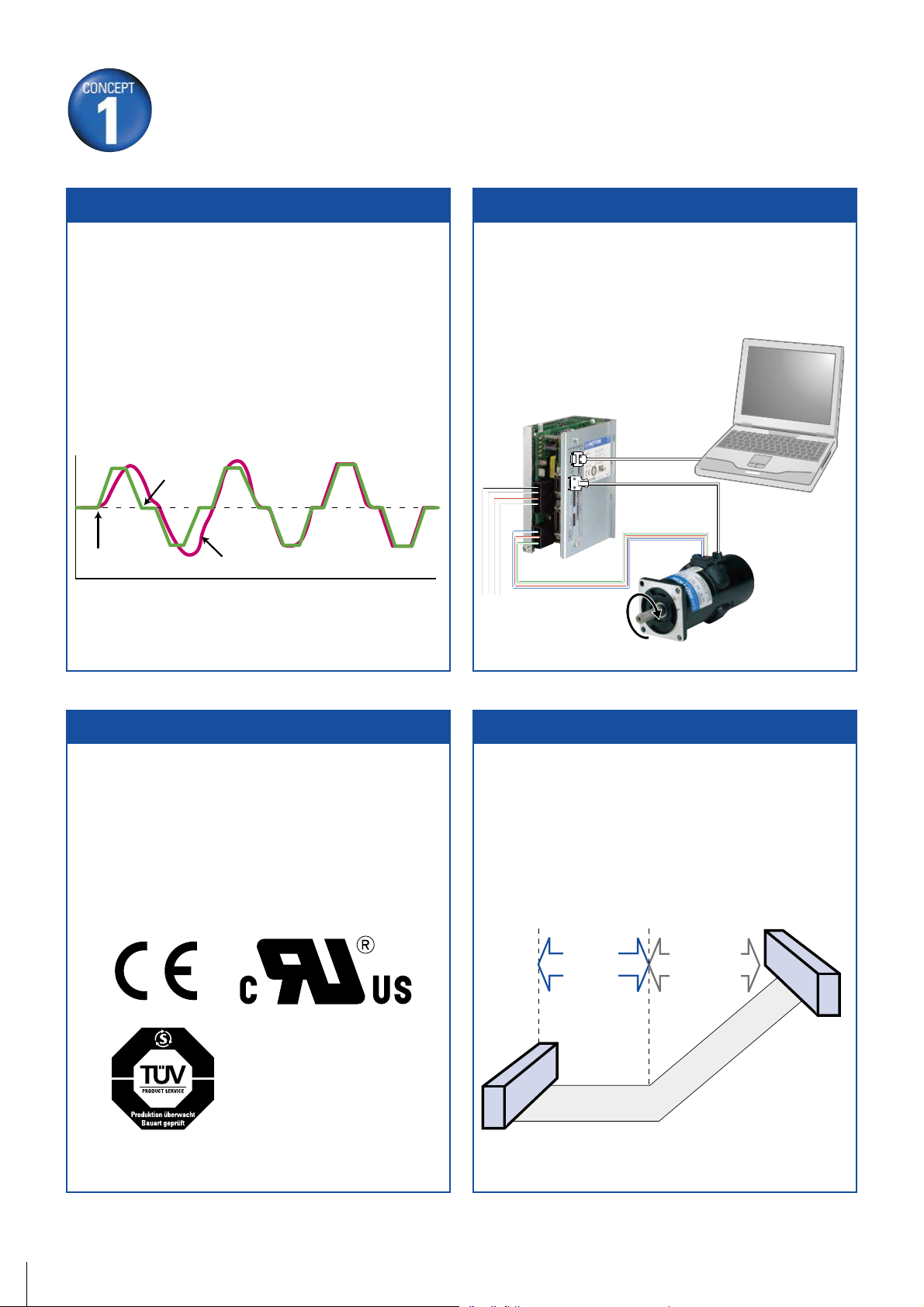
Auto-Tuning
A new auto-tuning algorithm improves system response by
providing functions such as inertia identification, 5 autotuning modes, 30 levels of response, and parameter setting
auto-save.
Velocity command
value
Tuning start
Detected velocity value
Test Function (JOG)
On-board JOG operation function is available for testing
servo motor and servo amplifier connection without the
need to connect to host device.
Capable of JOG operation
without connecting
to host device
Setup Software is required.
Conformance to Overseas Standards
Our standard servo amplifier has attained the UL, c-UL and
EN standards. You can also employ servo motors that have
attained the EN standards.
All-in-One Control
Configurable parameters allow you to switch between
control modes for torgue, position or velocity.
Position
Velocity
START
or
Flat
Torque
control
Ascending
GOAL
1
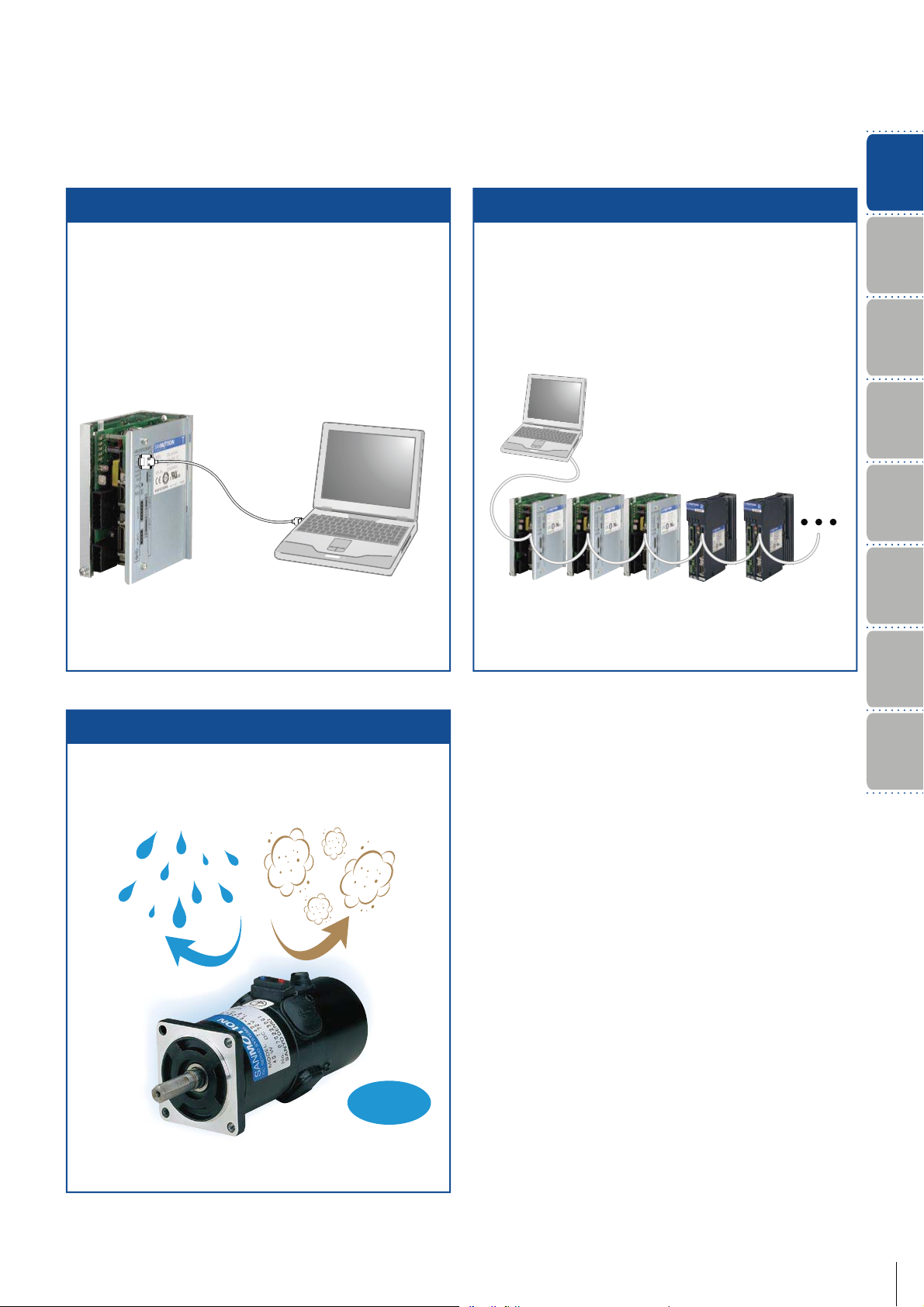
Setup Software
Multiaxial Monitor Function
Functions
Features and
The setup software allows you to set parameters, view
graphical displays of monitored position, velocity or torque
waveforms, and perform system analysis.
Parameter settings Position, velocity,
torque waveforms
*
*Use optional cable
AL-00490833-01 for PC connection
The setup software allows up to 15 servo amplifiers to be
monitored.
Daisy chain up to 15 units
*
DC SERVO SYSTEMS AC SERVO SYSTEMS
*Use optional cable
For PC connection
Maximum
15 units
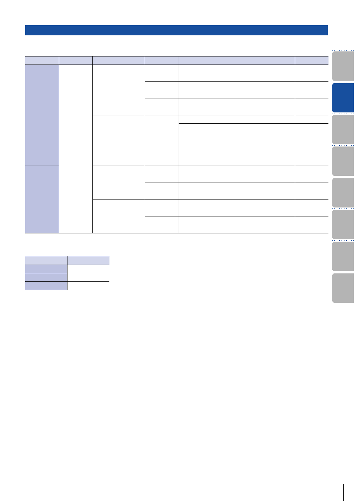
Nomencalture
Model Number
System
Configuration
Standard
Specifications
Diagram
External Wiring
Dimensions
Setup Software
Protection Code IP43
Protection code is IP43 for all models.
Water
Shaft feedthrough and cable end are excluded.
Dust
IP43
Optional
Equipment
2
Improved Systems Precision and Shortened Cycle Time
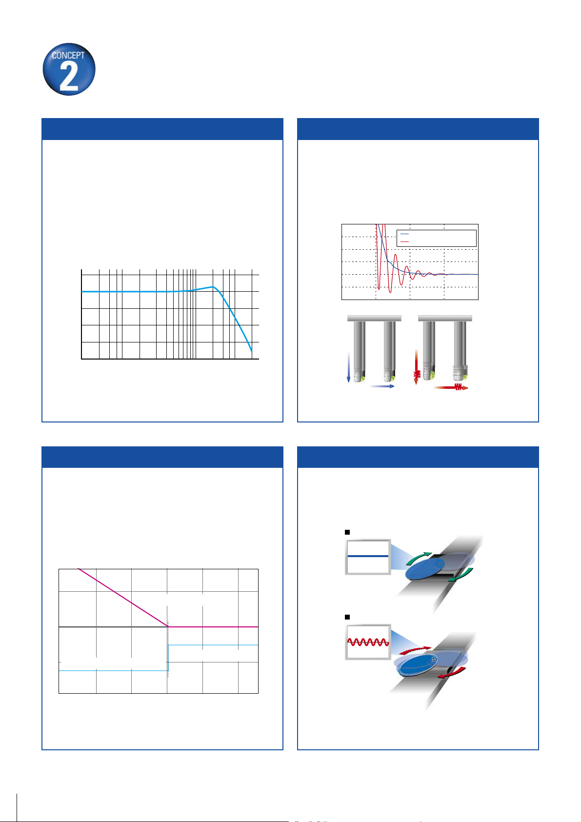
High Response
A 4th-order notch filter reduces phase delay to suppress
mechanical resonance and improve velocity response of
equipment.
10
0
-10
-20
Gain (dB)
-30
-40
1
5 10 50100 500 1000
Frequency (Hz)
Vibration-damping Control
With feed-forward vibration suppression control, vibrations
at the processing point and base of a machine can be
suppressed through simple tuning procedures. Up to 4
types of vibration control frequencies can be selected.
Position deviation during stop
With vibration suppression control
Without vibration suppression control
With vibration
suppression control
17-bit absolute encoder is required.
Without vibration
suppression control
100ms/div
Shorter Position Settling Time
A new algorithm drastically shortens positioning settling
time for equipment.
Position deviation
Position complete signal
Example of positioning settling time
in highly rigid machinery
Settling time (0ms)
5ms/div
Disturbance Suppression
It is possible to control impacts from other axes in case
of multiaxial constitution, by using the new disturbance
observer with extended applicable frequency.
Disturbance observer function ON
Oscillation waveform
of direct drive section
Disturbance
Disturbance observer function OFF
Oscillation waveform
of direct drive section
Disturbance
17-bit encoder is required.
3
High Resolution
Curtailed Running Cost
30% Reduction in Power Loss
Functions
Features and
Control suitable for the high-resolution incremental
encoder and absolute encoder can be performed.
0
4
1
8
n
o
i
t
u
l
o
s
e
R
m
u
m
i
x
a
5
7
6
d
i
v
i
s
i
o
n
s
M
A low-power loss module has been employed to reduce the
power loss in the main circuit by 30%.
100%
90%
80%
70%
60%
50%
40%
30%
20%
10%
Reduction rate of power loss
0%
SANMOTION TCurrent model
Nomencalture
Model Number
System
Configuration
Standard
Specifications
Diagram
External Wiring
Dimensions
Setup Software
Optional
Equipment
4

Servo Motor Standard Model Number List
Rated Output
23W
40W
60W
110 W
200W
300W
400W
500W
Outer diameter
of motor
φ
41mm
φ
41mm
φ
41mm
φ
51mm
φ
51mm
φ
76mm
φ
76mm
φ
87.5mm
φ
87.5mm
Encoder
―
Incremental encoder (PP031) 1000P/R
―
Incremental encoder (PP031) 1000P/R
―
Incremental encoder (PP031) 1000P/R
―
Incremental encoder (PP031) 1000P/R
―
Incremental encoder (PP031) 1000P/R
―
Incremental encoder (PP031) 1000P/R
―
Incremental encoder (PP031) 1000P/R
―
Incremental encoder (PP031) 1000P/R
―
Incremental encoder (PP031) 1000P/R
Tachometer
generator
―
Winding
specifications
Model No.
T402- 011
With T402T-011
―
―
24VSystem
T402- 011EL8
T404 - 011
With T404T-011
―
With T404T-012
―
―
With
―
―
With
―
―
With T511T-012
―
―
With T720T-012
―
―
With T730T-012
―
―
With T840T-012
―
―
With T850T-012
―
For specifications on other model, please contact us.
75VSystem
24VSystem T404-011EL8
System T404-012EL8
75V
24VSystem T406-011
System T406-012
75V
System T406T-011
24V
System T406T-012
75V
24VSystem T406-011EL8
System T406-012EL8
75V
24VSystem T506-011
System T506-012
75V
System T506T-011
24V
System T506T-012
75V
24VSystem T506-011EL8
System T506-012EL8
75V
75VSystem
75VSystem
75VSystem
75VSystem
75VSystem
T404 - 012
T511- 012
T511- 012 EL8
T720-012
T720-012EL8
T730-012
T730-012EL8
T840-012
T840-012EL8
T850-012
T850-012EL8
5
Servo Amplifier Standard Model Number List
Main power
DC140V
DC50V
Control power
DC24V
Control system
Pulse train,Speed,
Tor que
Speed,Torque
Pulse train,Speed,
Tor que
Speed,Torque
Amp. capacity
Detector Model No.
20A Incremental encoder TS1A02AA
25A Incremental encoder TS1AA2AA
30A Incremental encoder TS1A03AA
20A
Tachometer generator (Motor model T4) TS1A02AN
Tachometer generator (Motor model T5)TS1A02AP
25A Tachometer generator(Motor model T5,T7) TS1A A2 AP
30A Tachometer generator (Motor model T8) TS1A03AP
20A Incremental encoder TS1B02AA
25A Incremental encoder TS1BA2AA
20A Tachometer generator (Motor model T4) TS1B02AN
25A
Tachometer generator (Motor model T4) TS1BA2AN
Tachometer generator (Motor model T5)TS1BA2AP
For specifications on other model, please contact us.
Functions
Features and
Nomencalture
Model Number
System
Configuration
Standard
Specifications
Diagram
External Wiring
Dimensions
Power unit
Output capacity Model No.
5ATS1PA0500
10A TS1PA1000
15ATS1PA1500
Setup Software
Optional
Equipment
6
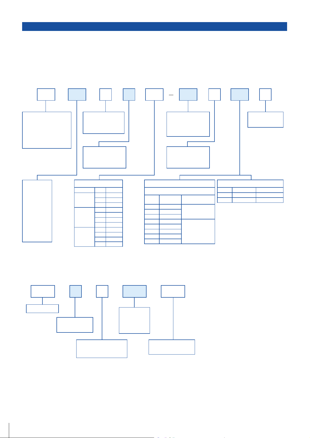
Servo Motor / Power Unit Model Number Nomenclature
Servo Motor
Example : The model number is as follows when 200W rated output, 76mm outer diameter,
incremental encoder (1000P/R), a brake, tachometer generator, gear (1/15 gear ratio),
and 75V series voltage specification are selected for "SANMOTION T" servo motor:
Model
Outer diameter
of motor
T4‥‥‥‥‥ φ41 mm
T5
‥‥‥‥‥ φ51 mm
T7
‥‥‥‥‥ φ76 mm
T8
‥‥‥‥‥ φ87.5 mm
Rated output
02‥‥ 23W
04
‥‥ 40W
06
‥‥ 60W
11
‥‥ 110W
20
‥‥ 200W
30
‥‥ 300W
40
‥‥ 400W
50
‥‥ 500W
20
Brake
B‥‥‥ Equipped
None
‥
Not equipped
Tachometer generator
T‥‥‥ Equipped
None
‥
Not equipped
Gear
Motor model Gear ratio
model
model
model
T4
T5
T7
Model No.
GA
1/12.5
1/25
GB
GC
1/50
G1
1/15
G2
1/30
G3
1/60
G4
1/90
G6
1/15
G7
1/30
G8
1/60
G9 1/90
TB
G6
Specification identification
01‥‥‥‥ Standard
Other
Winding specifications
(W/O oil seal)
‥‥ Option
2T7 01 EL8
U
None‥ Standard
U‥‥‥UL
1‥‥ 24V series
2
‥‥ 75V series
Incremental Encoder
Line driver output
Output
Model No.
pulse number
EL8
EL0
E59
EAL8
EAL0
EA59
EA51
EA53
・No indication: No encoder
※
T4 type can be equipped with either tacho-generator or
encoder only. It cannot be equipped with brake oil seal.
※
Motors with a rated output of 23W, 40W, and 60W support
the 24V winding specification.
1000
2000
2500
1000
2000
2500
5000
10000
Encoder type
PP031
PP031T
Quick response
specifications
Absolute encoder
Number of bits
Model No.
A12
A22
17
20
Baud rate
2.5Mbps
2.5Mbps
Power Unit
7
TS1 series
Unit structure type
Power Unit
‥‥
Input voltage Note)
‥‥
(for common use)
Note) Supply AC100V if the motor
winding specification is 75V
series and supply AC35V if
it is 24V series.
ATS1 10 00P
100V AC or 35V AC
Output capacity
05‥‥ 5A
10
‥‥ 10A
15
‥‥ 15A
Individual specification
‥‥ Standard product
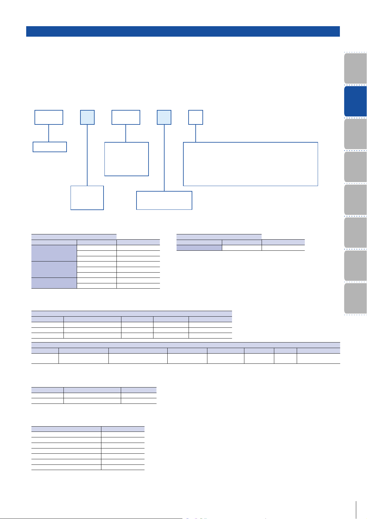
Servo Amplifier Model Number Nomenclature
Servo Amplifier
Example: The model number is as follows when "SANMOTION T "series servo amplifier with input voltage
of DC140V, 20A capacity, and incremental encoder (1000P/R).
A AATS1 02
TS1 series
Input voltage
A…DC 140V
B
…DC 50V
Amp. capacity
02 ‥‥‥‥ 20A
A2
‥‥‥‥ 25A
03
‥‥‥‥ 30A
Motor structure type
‥‥
Rotary motor
Control unit hardware type Note)
A ‥‥‥‥ Incremental encoder (Line driver output only)
F
‥‥‥‥ Absolute Encoder
N ‥‥‥‥ Tacometer generator (Motor model T4)
P
‥‥‥‥ Tacometer generator (Motor model T5,T7,T8)
Note) Tacho-generators have not attained international
standards (UL, c-UL and EN Standards).
Functions
Features and
Nomencalture
Model Number
System
Configuration
Standard
Specifications
Diagram
External Wiring
1 )Compatible servo motor type
Input voltage-140V DC
Type of Amplifier. Type of Motor Factory settings
TS1A02 A
TS1AA 2A
TS1A03A
T404-012
T406-012
T506- 012
T511-012
T720-012
T730-012
T840-012
T850-012
2 )Compatible encoder type
Format Divisions per rotation [P/R] Addreviation Hard type. Factory settings
Optical 1000 INC-E
Optical 2000 INC-E
Optical 2500 INC-E
Format Transmission format Divisi ons per rot ation [P/ R] Multiple rotation Addreviation Hard type. Remarks Factory settings
Optical
Half duplex start-stop
synchronization 2.5M
Note)
Note)
Incremental encoder
Input voltage-50V DC
√
√
√
17bit 16bit PA035C-2.5MH
Type of Amplifier. Type of Motor Factory settings
TS1B02A T402-011
A
A
A
Absolute encoder
√
√
F
3 )Compatible tacometer generator
Motor Model Tacometer generator Model Hard type
T4 3V / 1000min
T5, T7, T8 7V / 1000min
-1
-1
N
P
Dimensions
Setup Software
Optional
Equipment
√
4 )Interface for control section
Control type Factory settings
Velocity control type
Torque control type
Position control type
Velocity - Torque switch type
Position - Torque switch type
Positio n - Velocit y switch type
Internal velocity control type
Note)
√
Note)Please change the compatible servo motor, compatible encoder and the interface for control section using the set-up software.
8
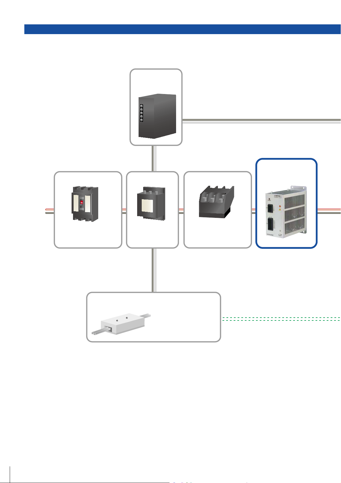
System Configuration
Circuit Breaker (MCCB)
Main
power
supply
AC100V
50/60Hz
Control power supply:
DC24V output
Noise Filter
Electromagnetic Contactor
Power unit:
DC140V output
Cuts off power in the case of
an overload, to protect the
power line.
Brake Power
Protects the power line
from external noise, and
from noise generated
by the servo amplifier.
Required for use when the
servo motor is equipped
with a brake.
Switches servo power on
and off. Requires installation
of a surge protector.
9
Functions
Features and
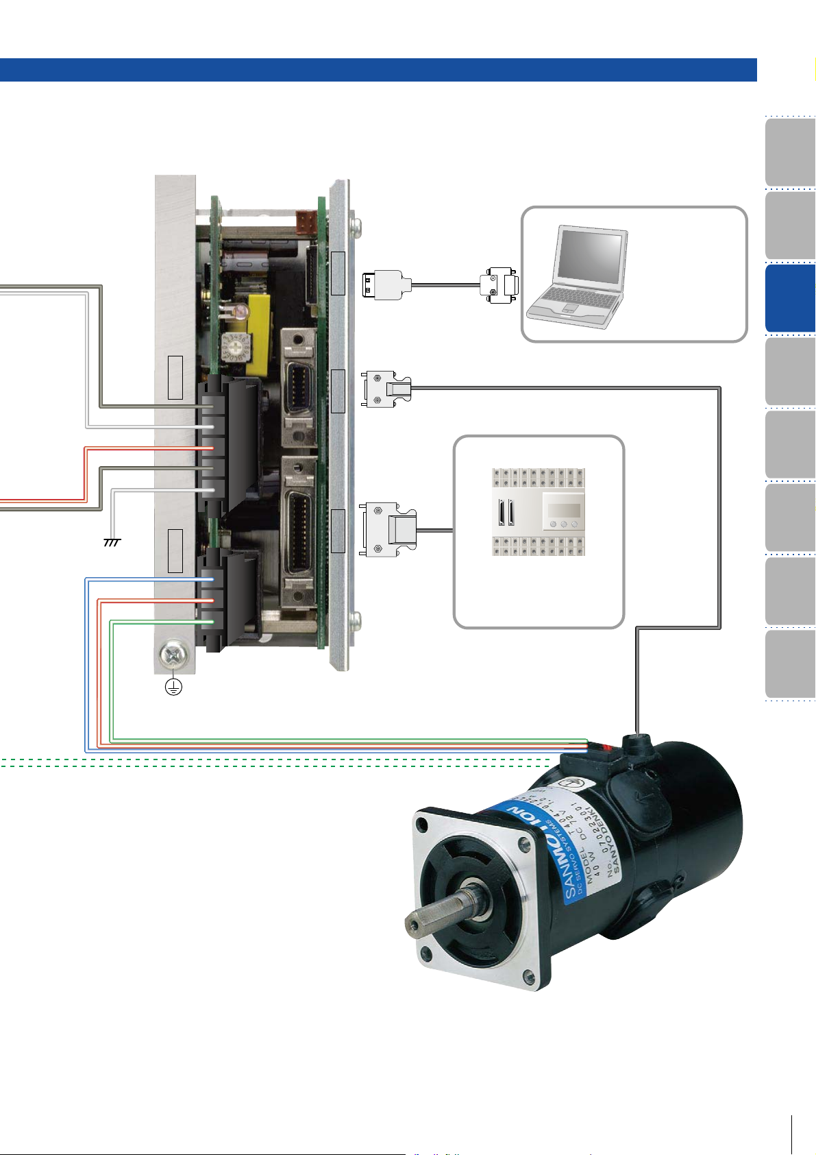
Setup Software
C
N
5
CN5
AL-00490833-01
Parameter
configuration and
monitoring is possible
via communication
with a PC.
Nomencalture
Model Number
System
Configuration
C
N
3
C
N
2
CN2CN2
Host Devices
Standard
Specifications
Diagram
External Wiring
C
C
N
4
N
1
Dimensions
CN1
SANYO DENKI's host devices
permit communication with
third-party products.
Setup Software
Wiring required for brake.
Optional
Equipment
10
 Loading...