

Sankyo SANDEX-Alpha 11AR Operation And Maintenance Manual
11AR
ALPHA SERVO DRIVE INDEX
Optimum Reliability in Motion Control
OPERATION AND MAINTENANCE MANUAL
SERVO DRIVE TYPE
Preface
Thank you for purchasing a SANDEX product. These instructions cover installation procedures, linkage
procedures, and maintenance precautions to be followed to ensure maximum performance from this
product. Please read these instructions carefully before installing or trial operating of this product.
After unpacking, make sure the product delivered fits your ordering specifications.
99 ARAR -- S01S01 AA 00 00 00 00 XX
|
aa | bb
|
cc
|
dd
|
ee
|
ff
|
gg
|
hh
|
II
a: Size
Shaft to shaft distance
Availability: 7=70mm, 9=90mm, 11=110mm, and 15=150mm
b: Model
AR=Alpha series Roller drive type
c: Roller Drive
Type of roller drives
Availability:
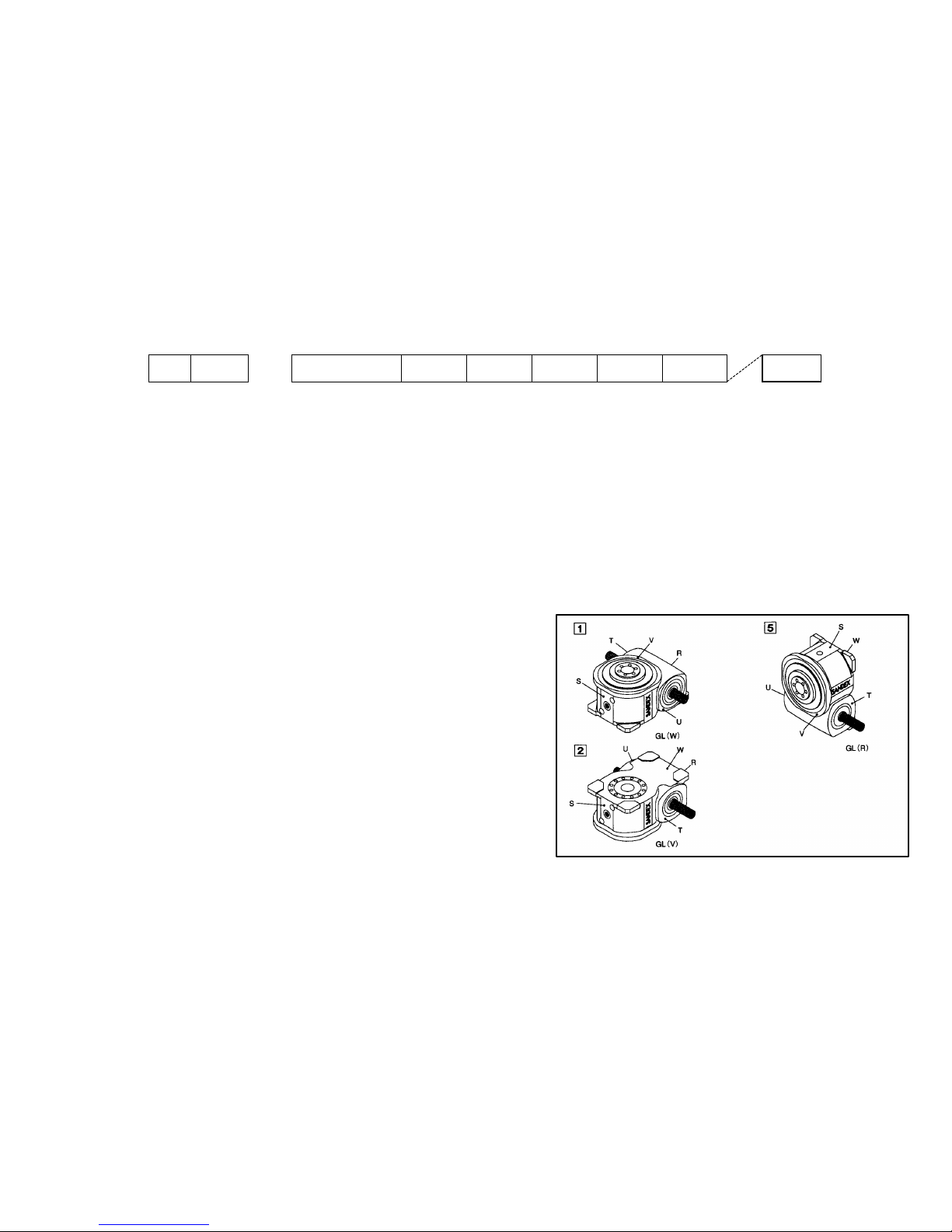
S01=Roller gear ratio; 1/12, Mounting position; 1
S02=Roller gear ratio; 1/12, Mounting position; 2
S05=Roller gear ratio; 1/12, Mounting position; 5
d: Motor & Bracket
Type of Motor & Bracket
Availability:
A=Standard (Pulley ratio; 7&9AR=1/3, 11&15AR=1/2)
April 2002
e: Motor Driver
Type of Motor Driver
Availability:
11

0=Single phase 200 to 230VAC for 7AR & 9AR
1=Three phase 200 to 230VAC for 11AR & 15AR
2=Three phase 380 to 480VAC for 11AR & 15AR
f: Controller
Type of controller
Availability:
0=Standard
x=Special requirements
g: Cable
Type of cables
Availability:
0=3 meters length, w/o conduit
1=5 meters length, w/o conduit
2=10 meters length, w/o conduit
3=15 meters length, w/o conduit
4=3 meters length, w/ conduit
5=5 meters length, w/ conduit
6=10 meters length, w/ conduit
7=15 meters length, w/ conduit
Y=Connectors Only
h: Control Software
Type of control software
Availability:
0=Standard
x=Special requirements
I: Special Instructions
Include the symbol X in case of special orders
No symbols= Standard
22
Safety Precautions
Symbols to ensure the safe and proper use of the Variax
The following symbols are used this manual where safety precautions must be observed. Read
and understand the meanings of these symbols to ensure the safe and proper use of Variax.
Failure to obey these precautions can cause machine problems, accidents, or other unexpected
behavior.
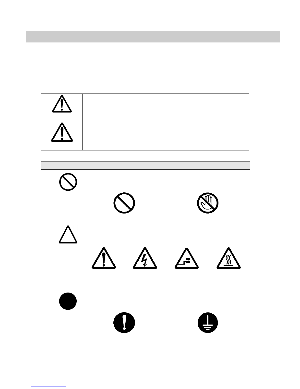
Indicates a potentially hazardous situation, which may result
in death or serious injury.
Warning
Indicates a potentially hazardous situation, which may result
in minor or moderate personal injury or damage to the
Caution
equipment.
Meaning of symbols
In general, this symbol alerts you to an action or operation that you
must not do.
General prohibition
Do Not Touch
In general, this symbol alerts you to the possibility of damage
to you or your equipment.
General
Warning
Electrical
Hazard
Pinch Point
Temperature
High
This symbol alerts you to actions that are reserved for
qualified service personnel only
Mandatory Action
Electrical Grounding
33

Contents
PREFACEPREFACE
SAFETY PRECAUTIONSSAFETY PRECAUTIONS
SAFETY PRECAUTIONSSAFETY PRECAUTIONS 33
SSYMBOLS TO ENSURE THEYMBOLS TO ENSURE THE SAFE AND PROPER USE SAFE AND PROPER USE OF THE OF THE VVARIAXARIAX 33
1. OPERATING THEORY1. OPERATING THEORY 66
2. HANDLING YOUR SA2. HANDLING YOUR SANDEXNDEX 77
2.12.1 IIDENTIFYING DENTIFYING AALPHA LPHA SSERVO LAYOUTERVO LAYOUT 77
3. TRANSPORTATION A3. TRANSPORTATION AND ENVIRONMENTND ENVIRONMENT 88
3.13.1 SSHIPPING CONDITIONHIPPING CONDITION 88
3.2 3.2 TTEMPERATURESEMPERATURES 88
3.33.3 MMOISTUREOISTURE 88
3.43.4 DDUSTUST 88
4. INSTALLATION4. INSTALLATION 1010
4.1 CASING MAIN BODY 1010
4.2 DRIVER 1010
4.2.1 STORAGE CONDITIONS 10
4.2.2 INSTALLATION SITE 11
4.2.34.2.3 ORIENTATIONORIENTATION 11
4.2.44.2.4 WIRING THREE PHASE 2WIRING THREE PHASE 200VAC00VAC 12
4.2.54.2.5 WIRING THREE PHASE 4WIRING THREE PHASE 400VAC00VAC 13
4.3 CONTROLLER 1414
4.3.1 MOUNTING THE MP940 14
4.3.24.3.2 CONNECTION OF PERIPHCONNECTION OF PERIPHERAL DEVICESERAL DEVICES 15
4.44.4 WWIRINGIRING 1616
4.4.14.4.1 I/O CIRCUITSI/O CIRCUITS 17
4.4.24.4.2 CONTROLLER I/O CONNECONTROLLER I/O CONNECTIONSCTIONS 18
5.OPERATION5.OPERATION 1919
5.15.1 SSETTING ENCODER ZERO ETTING ENCODER ZERO POSITIONPOSITION 1919
5.25.2 SSETTING ZERO POSITIONETTING ZERO POSITION ((STARTING POSITIONSTARTING POSITION)) 1919
5.35.3 I/O I/O TIMING CHART WHILE ITIMING CHART WHILE IN JOG MODEN JOG MODE 2020
5.45.4 I/O TIMING CHART WHILE IN AUTOMATIC MODE 2121
5.55.5 IINDEXING TIME VSNDEXING TIME VS. . STOPS CHARTSTOPS CHART 2222
44

5.65.6 DDATA SWITCH SETTINGSATA SWITCH SETTINGS 2222
6. HANDLING PROCEDU6. HANDLING PROCEDURES FOR THE RES FOR THE OUTPUT SHAFTOUTPUT SHAFT 2323
6.16.1 TTABLE TYPE OUTPUTABLE TYPE OUTPUT 2323
7. LUBRICATION7. LUBRICATION 2424
4.54.5 PPURPOSE OF LUBRICATIOURPOSE OF LUBRICATIONN 2424
7.27.2 OOIL SELECTION PRECAUTIL SELECTION PRECAUTIONSIONS 2424
7.37.3 LLUBRICATING OIL VISCOUBRICATING OIL VISCOSITYSITY’’SS 2525
7.47.4 RRECOMMENDED LUBRICATIECOMMENDED LUBRICATING OILNG OIL 2525
8. FILLING AND REPL8. FILLING AND REPLACING LUBRICATING OIACING LUBRICATING OILL 2626
8.18.1 RREFILLING LUBRICATINGEFILLING LUBRICATING OILS OILS 2626
8.28.2 OOIL REPLACEMENT SCHEDIL REPLACEMENT SCHEDULEULE 2626
9. LUBRICATION GREA9. LUBRICATION GREASESSES 2727
9.19.1 SSUPPLYING LUBRICATINGUPPLYING LUBRICATING GREASE GREASE 2727
10. REPAIRS AND MAI10. REPAIRS AND MAINTENANCENTENANCE 2828
10.110.1 YYASKAWA ASKAWA DDRIVER AND RIVER AND CCONTROLLERDISPLAY CODONTROLLERDISPLAY CODESES 2929
10.210.2 TTROUBLESHOOTING PROCEROUBLESHOOTING PROCEDURES DURES (1)(1) 3131
10.310.3 TTROUBLESHOOTING PROCEROUBLESHOOTING PROCEDURES DURES (2)(2) 3232
55

Unit 2
Handling your Sandex
1. Operating theory
SANDEX units operate based on the following principal. A globoidal cam is mounted onto the input
shaft. This cam interlocks with the turret portion of the output shaft. The turret has cam followers along
its perimeter, which are in contact with the tapered ribs on the cam. This contact or pressure is called
the preload. Turning the input shaft rolls the cam followers along the rib surfaces thereby rotating the
turret according to the curve of the cam. The turret is motionless when the ribs are parallel with the
edges of the cam although the cam followers stay in motion.
Two of three cam followers are always kept pressed against the tapered ribs to ensure an accurate
transmission of rotation. Any backlash or movement between the tapered rib surfaces and cam
followers can cause vibrations, noise, and also damage the cam and cam follower surfaces. Backlash
can be completely eliminated by rotating the eccentric flange that holds the input shaft, and minimizing
the distance between the input and output shaft.
Explanation of terms used with indexing equipment
TERM DEFINITION
The number of stops determined by the customer’s programming.
Number of stops
A predetermined number of stops have been programmed into the
controller (1-16) CW or CCW.
Index angle The index angle is dependant on the number of stops.
Dynamic Torque output
rating(Top)
The maximum torque that can be applied on the output shaft
during indexing phases. Directly related to machine life.
66
Unit 2
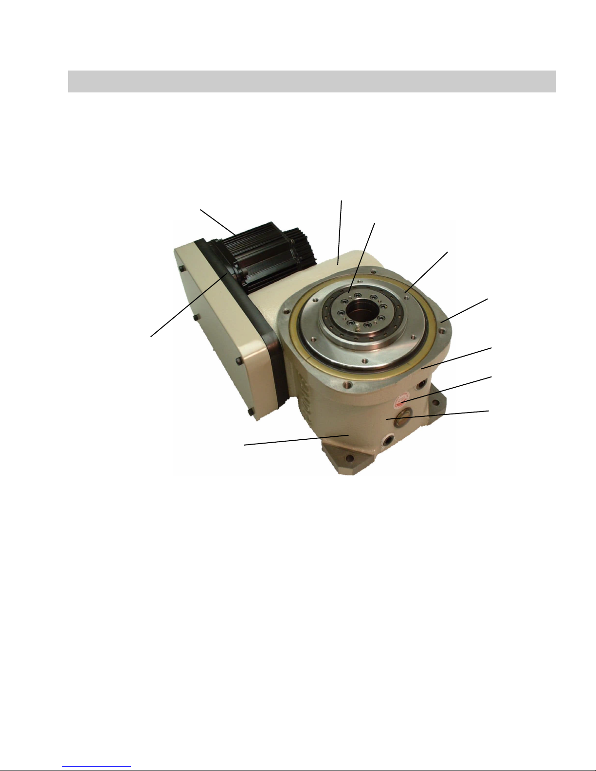
Roller Drive
Mounting hole
Handling your Sandex
2. Handling your SANDEX
Over 90% of the mechanical failures reported with roller gear cam equipment comes from careless
or improper handling. Improper handling not only reduces the life of your SANDEX unit, it can also
affect the performance of both the SANDEX unit and your machine.
2.1 Identifying Alpha Servo layout
Servomotor
Servomotor
mounting bracket
Fixed hollow flange
Installation surface
for indexing table.
Installation for
fixed table.
Oil cap
at W-surface
2.2 Handling your Alpha Servo
(1) Torsion and deflection within the rotation transmission system
(2) Frictional torque within the rotation transmission system
(3) Frequent load charge
(4) Usage under rust stimulant conditions such as water, acid, or alkali
(5) Usage in dusty areas
(6) Electrical currents
(7) Improper maintenance and repairs
(8) Mounting areas with insufficient rigidity
Oil gauge
*Drain
77

Unit 3
Transportation and environment
3. Transportation and Environment
3.1 Shipping condition
(1) All SANDEX products are thoroughly inspected after the final assembly. Only those
products that pass this inspection are shipped.
(2) Before shipped, each SANDEX unit is filled with lubrication oil in accordance to the
customer’s operating speed and environment.
(3) A rust preventative solution is applied to the input /output shafts, key, and mounting
surface. Vinyl tape is also used extensively to protect your SANDEX unit from
scratches while transporting.
Remove the rust preventative solution with a light oil or thinner. Be careful not to let the
light oil or thinner contact the oil seal. Never use thinner on or near the plastic sight gauge.
This may cause severe clouding of the material.
3.2 Temperatures
(1) For use between -20 to 0 degrees Celsius, (-4 to 32°F) use a lubricating oil with a lower
viscosity than the recommended oil. This is because the dynamic viscosity of the
lubricating oil rises in low temperatures and may not allow proper speed acceleration.
(2) For use between 40 to 70 degrees Celsius, (104 to 158°F) use lubricating oil with a
higher viscosity than the recommended oil. This is because the dynamic viscosity of the
lubricating oil lowers in higher temperatures and reduce the life of the equipment.
(3) For use between 70 to 100 degrees Celsius, (158 to 212°F) replace the oil seal and O-ring
with a heat resistant synthetic rubber.
3.3 Moisture
Rust may occur in storage or if the main machine is washed with water. Water does not
have to come directly into contact with the unit to cause rust. Moisture, condensation, and
other sources of humidity can also cause rust.
To use under these conditions, the mounting surfaces and shafts of the unit must be
painted, or otherwise rust proofed. Applying mineral oil or grease to the mounting surfaces
has a rust preventative effect and should always be practiced.
In addition, if the unit is directly subject to water, the sealing devices on the input and
output must be changed to a waterproof construction.
3.4 Dust
SANDEX units are generally built resistant to dust. This is because the roller gear cam
mechanism is enclosed within its own housing, and then sealed off at the input and output
with an oil seal. However, depending on the amount of dust or other foreign particles, the
88

Unit 3
Transportation and environment
oil seal may wear and thereby cause oil leaks. This is particularly evident when chemicals
are used. Chemicals can also cause andor accelerate rust and corrosion. When using
your SANDEX unit in dusty areas, you should consider using protective covers made from
stainless steel or plastic.
If the location for your SANDEX unit is very dusty, the air outlet in the oil
fill port may become an entrance into the housing. Placing an air filter over
this port should prevent dust from entering the housing. Electrical currents
If electricity passes through the SANDEX unit, minute dimples can occur on the cam
followers and roller gear cam, as well as on the rolling surfaces and members of the
bearings.
““Electrolytic corrosion” is where electrical sparks actually melt away the surfaces of
the rolling members. Electrolytic corrosion is a current-based effect. Therefore, it can
occur under less than one volt of electrical power.
If your SANDEX unit may be subject to electrical currents, make sure to insulate it.
Electrolytic corrosion, if allowed to persist, will increase the amount of vibration and noise,
and eventually render your SANDEX unit useless. Always insulate the table and unit from
welding applications or other automated machinery that use large amounts of electrical
current.
When linking the motor with the input system, consider using rubber couplings instead
of metal types. Rubber provides more insulation. Other measures that can prevent
electrolytic corrosion include using V-belts and timing belts.
99

Unit 4
Installation
4. Installation
Another crucial factor to the performance of your SANDEX unit is the operating environment. Make an
early review of the location for your SANDEX unit and take any corrective actions necessary.
4.1 Casing main body
(1) Always use the lifting bolt holes provided on the housing of your SANDEX unit. Do not lift
the unit using the input or output shafts as this can affect the precision of the equipment, or
worse, affect the life of the machine.
(2) Each SANDEX unit has oil fill, drain and sight gauge ports. The unit should be mounted for
easy maintenance access to these ports.
(3) To ensure that your SANDEX unit is mounted accurately in the best possible position, make
sure the housing, shaft dimensions, and mounting holes comply with drawing specifications.
Also check the mounting area for perpendicularity and flatness. If the mounting surface has
any scratches, burrs, debris, or paint, use an oilstone or emery paper to remove it. Next,
clean the mounting surface and apply a light coat of grease or mineral oil to prevent rust
and scratches. You may now mount your SANDEX unit. Never install the unit in a position
not specified for your particular product.
(4) Align your peripheral equipment with the input and output shafts on the SANDEX unit to
ensure the best possible mounting position.
Apply Loctite 242 or equivalent screw locking solution to the mounting bolts, and tighten to
the specified torque with a torque wrench. (Tightening torque: DIN 8.8)
(5) The foundation for your SANDEX unit must be rigid enough to withstand vibrations from
other machines. The foundation is crucial to the precision and life of your SANDEX unit.
To ensure maximum performance mounts your SANDEX unit on a foundation that is
smooth, flat, hard, and free from vibration.
The standard operating temperature range for SANDEX units is between 0 to 40 degrees
Celsius (32 to 104°F). For usage outside of this range, follow the tips below.
4.2 Driver
The SGDH servo amplifiers are base-mounted. Incorrect installation will cause
problems. Follow the installation instructions below.
4.2.1 Storage Conditions
Store the servo amplifier within the following temperature range, as long as it is
stored with the power cable disconnected. -20 to 85°C (-4 to 185°F)
1010
 Loading...