

Sanken Electric Co SI-7500A Datasheet

5-phase Stepper Motor Star Connection Unipolar Driver IC
SI-7500A
■ Ratings
(Ta = 25°C)
Absolute Supply voltage Output Junction Operating Storage
maximum current temperature ambient temperature
rating (V) (A) (°C) temperature (°C) (°C)
Type No. VCC Vb Io Tj Top Tstg
SI-7500A 40 8 1.2 +125 –20 to +80 –30 to +100
■ Characteristics
Electrical Operating supply voltage Output current Power down Vb input External *Input voltage *Input Trigger Trigger Trigger
charac- Ratio current
teristics breakdown voltage time frequency
(V) (mA/ø) (%) (mA) (V) (V) (mA) (V) (µs) (kHz)
VCC Vb IO IOPD/IO Ib VZ VIH1 VIH2 VIL IIH1 IIH2 Vtrig Ttrig Ftrig
Type No. min typ
max
min typ
max
min
typ max
min typ
max
SI-7500A 17 24 30 4.5 5 5.5 200 750 1000 35 50 100 15
■ Block diagram
Main power
supply V
Current
controller
Variable current
resistor
Trigger pulse
generator
Excitation signal
2-3 phase excitation
circuit
Rx
Auxiliary power supply Vb
Reference
voltage
Excitation signal
amplifier
Comparator
amplifier
zener diode
current pulse pulse pulse
voltage
max min max max max max max
CC
V
50 3.9 1.3 0.6 0.21 0.22 4.0 Vb 1.0 2.0 20 25
x1.5
Zener diode for
CC
canceling counter EMF
ZD
M
Counter EMF
Canceller
max
min
max
min
* Input voltage and input current
conditions
VIH1 : Vb = 5V, Q1 to Q5ON
RX = , IIN = 0.2mA
VIH2 : Vb = 5V, Q1 to Q5OFF,
IIN = 0.22mA
IIH1 : Vb = 5V, Q1 to Q5ON,
VIN = 3.7V
IIH2 : Vb = 5V, Q1 to Q5OFF,
VIN = 0.9V
(Ta = 25°C)
typ
typ
max
SI-7500A
■ Equivalent circuit diagram
w
q
@0
Q
6
R
1
R
D
11
D
6
u
R
46
Q
R
47
R
6
D
1
Q
11
R
11
1
R
16
R
21
26
!8
e y !0 !1 !7
r
i
R
36
R
37
R
41
MIC
1
R
31
Current detection
resistor Rs
t
o
Q
7
D12D
2
D7D
13
8
R
2
R
7
D
2
Q
12
R
42
R
12
R
R
R
32
Q
17
22
R
27
Q
8
R
3
R
8
D
3
Q
13
R
13
Q
3
R
18
R
R
23
28
!2
!5
Q
9
R
38
R
39
R
9
R
43
Q
R
44
R
19
R
24
R
34
!3
!6
Q
10
D14D
4
D9D
15
R
5
R
10
D
5
Q
10
15
MIC
R
15
Q
5
R
20
R
25
R
30R35
R
4
D
4
14
R
14
Q
R
29
!9
R
40
R
45
3
!4
43
SI-7500A
g
)
)
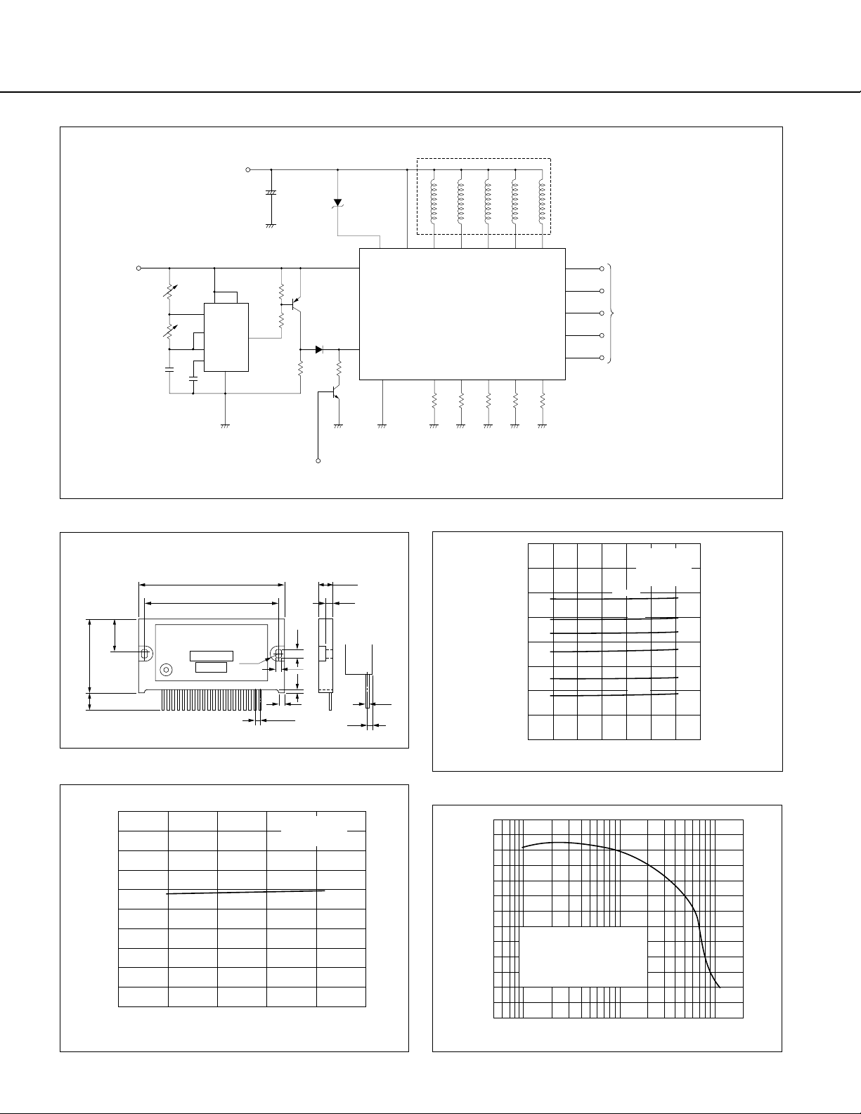
■ Diagram of external circuits
SI-7500A
Vb
V
R
44kΩ
V
R
300Ω
1000pF
8
7
2
6
5
0.01 F
555
1
µ
■ External dimensions
V
CC
+
100 F
µ
50V
1kΩ
4
3.9kΩ
3
2SA561
1S1555
1kΩ
Power down signal input
(Active hi
ZD
7
18
X
R
h)
(Unit: mm)
5-phase stepper motor
9522011316
OUT-4
OUT-3
OUT-2
OUT-1
V
ZD
CC
Vb
SI-7500A
Vief.
GND
11 3 6 10 14 17
R
S1
R
R
S3
S2
RS1RS2RS3RS4R
RS1 to RS5 : Current detection resistor
X
: Variable current resistor
R
■ Supply voltage vs. Output current
OUT-5
4
IN-1
8
IN-2
12
IN-3
15
IN-4
19
IN-5
R
R
S5
S4
S5
Excitation signal
input (Active High)
2-3 phase excitation
Plastic package
±0.5
±1
35.0
8.6
16.6
±0.5
69.0
±0.4
63.0
Type No.
Lot No.
....................................
12
8.0
φ
20Pin No.
3.4
P=2.54
1.8 3.8
3
7.0
±0.5
3.5
1.4
■ Case temperature vs. Output current
1.0
0.8
0.6
0.4
Output current Io (A)
0.2
0
0 25 50 75 100
Case temperature Tc (°C)
(Typical value)
V
CC
=24V
Motor : PH566-B
0.5
1.2
1.0
0.8
0.6
0.4
Output current Io (A)
0.2
0
2002430
Supply voltage VCC (V
■ Torque characteristics
2.5
2.0
(kg-cm)
OUT
1.5
τ
1.0
0.5
Pull-out torque
Supply voltage VCC = 24V
Vb = 5V
Output current Io = 0.8 A/phase (fixed)
Counter EMF canceler Zener diode Vz = 49V
Motor : PH566B
0
0 0.1 0.2 0.5 1 5
Response frequency f (kpps
Rx = ∞
(Typical value,
Motor : PH566-B
Rs = 1Ω
Vb = 5.0V
2kΩ
1kΩ
510Ω
200Ω
100Ω
2
10 20
44
 Loading...