

MA-19/25/66/67
Mobile GPS Antenna
SAN JOSE TECHNOLOGY, INC.
11F.,No.2,Sec.4, Jhongyang Rd. ,Tucheng City,
Tel: 886-2-2269-4456Fax: 886-2-2269-4451
USER'S MANUAL Rev. C
San Jose Technology,Inc. San Jose Technology,Inc.
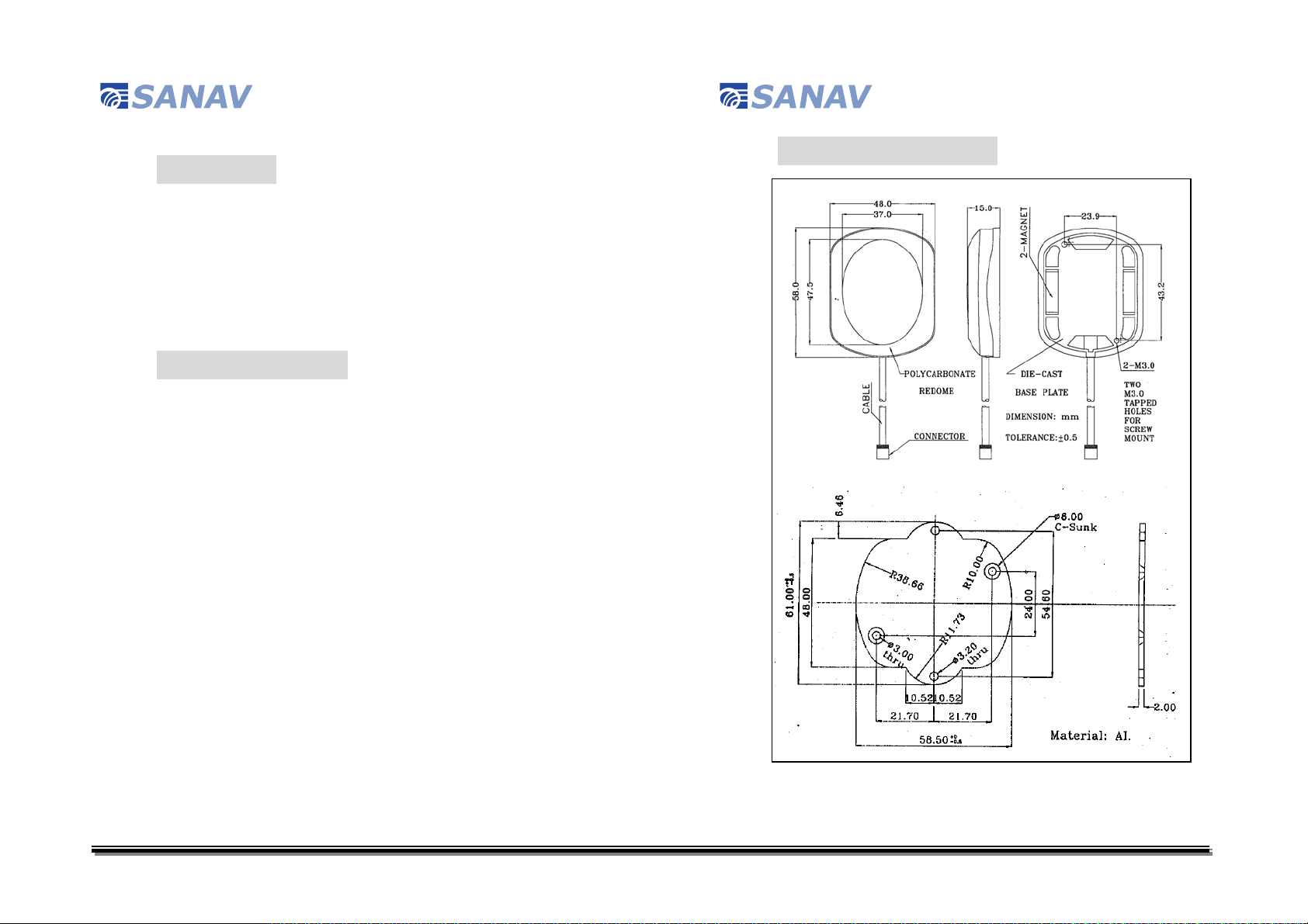
V. Technical Drawing
I. PREFACE
This text specifies the basic operational characteristics of the active
GPS antenna modules MA-19/MA-25/MA-66/MA-67 under a standard
test condition of 3V DC (MA-19)/ 5V DC (MA-25/66/67) & 25
50% R.H.
o
C/
II. INTRODUCTION
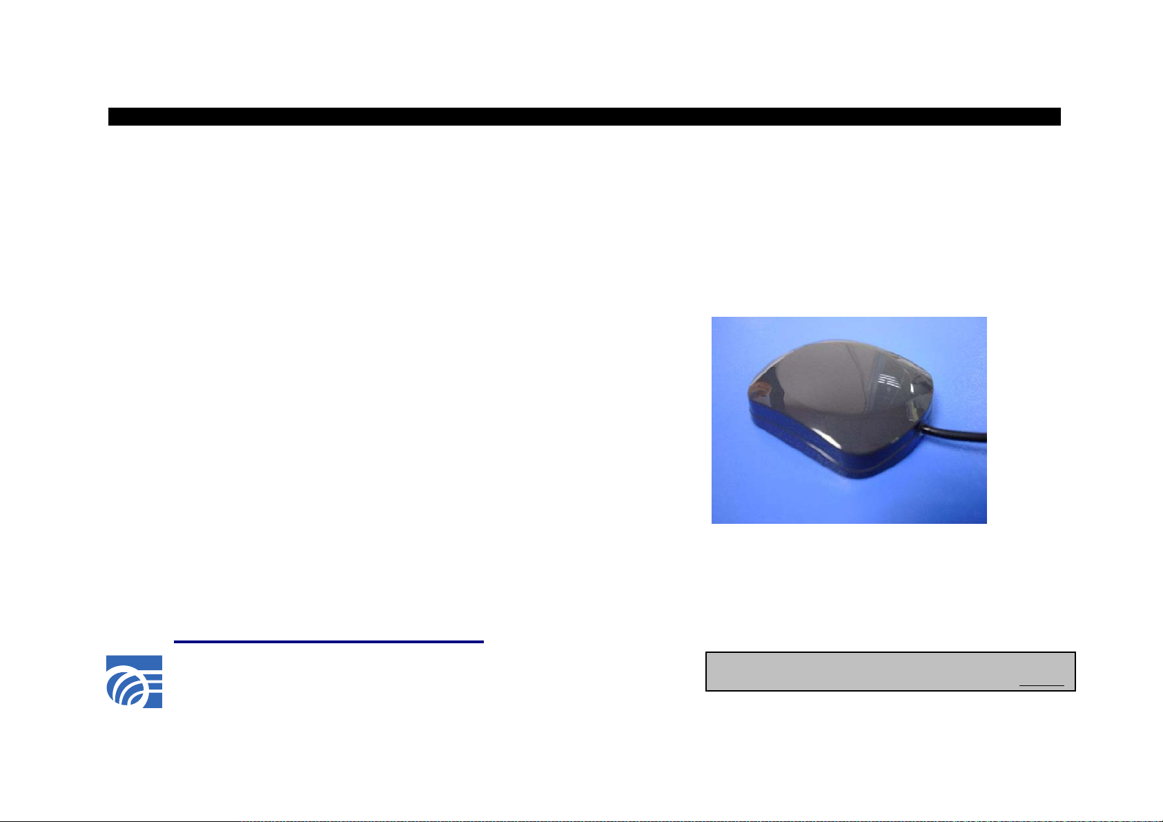
MA-19/MA-25/MA-66/MA-67 is the integration of a high
performance GPS patch antenna and a state-of-the-art low noise
amplifier into a very low profile/ extremely compact/ fully waterproof
enclosure which, when connected to a GPS receiver with 3V DC or 5V
DC antenna power, provides excellent signal amplification and
out-band filtering & rejection.
1
6
San Jose Technology,Inc. San Jose Technology,Inc.
IV. INSTALLATION
1. Secure your MA-19/MA-25/MA-66/MA-67 antenna to the top of
your vehicle and carry its cable into the vehicle.
2. Link the cable connector to your GPS receiver.
3. Start with your navigation.
III. SPECIFICATIONS
PHYSICAL
Construction: Polycarbonate-radome at top, die-cast
shell at bottom/ rubber gasket for water
seal in between
Dimension: 58mm (L) x 48mm (W) x 15mm (H)
Weight: 65 grams (excluding cable & connector)
Color of Radome: Standard in dark gray, other colors
available upon request
Standard Mounting: Magnet mount with two magnets
Optional Mounting 1: Screw mount with two M3 tapped holes
on the plastic flange of
MA-19/MA-25/MA-66/MA-67
Optional Mounting 2: Customized metal sheet
ANTENNA ELEMENT
Center Frequency: 1575.42 MHz +/- 1.023 MHz
Polarization: R.H.C.P. (Right Hand Circular
Polarization)
Absolute Gain at Zenith:
Gain at 10o Elevation: -1 dBi typically
Axial Ratio: 3 dB max.
Output VSWR: 1.8 Max.
Output Impedance: 50 ohm
+5 dBi typically
5
2

San Jose Technology,Inc. San Jose Technology,Inc.
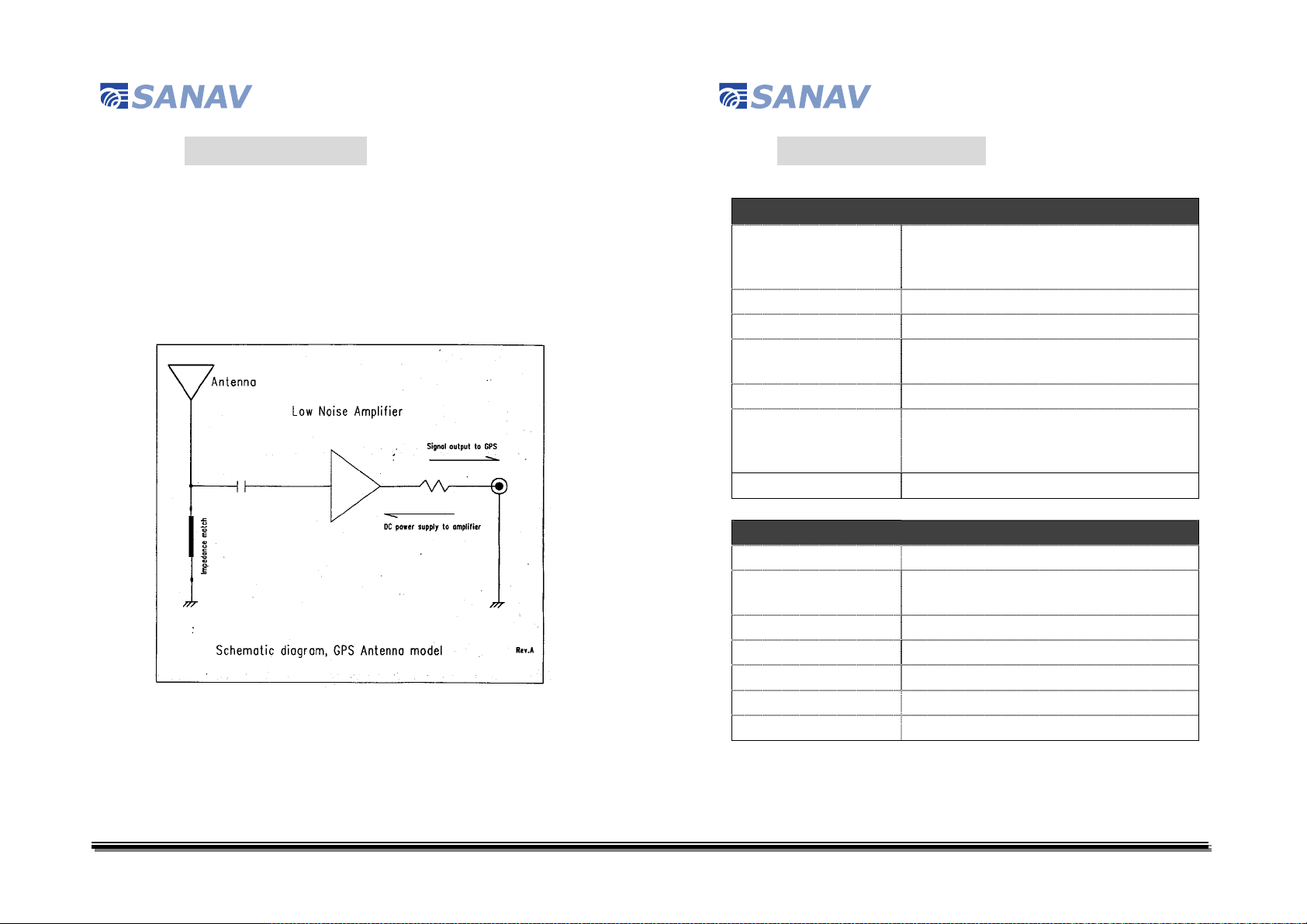
LOW NOISE AMPLIFIER
Center Frequency: 1575.42 MHz +/- 1.023 MHz
MA-19: 27 dB typically
Gain:
Band Width: 2 MHz min.
Noise Figure:
Out of Band Attenuation:
Supply Voltage:
Current Consumption:
VSWR: 2.0 max.
Output Impedance: 50 ohm
MA-25: 26 dB typically
MA-66: 30 dB typically
MA-67: 30 dB typically
MA-19: 1.3 max.
MA-25: 2.6 max.
MA-66: 1.5 max.
MA-67: 2.0 max.
20dB min. @F0 +/- 50MHz
MA-67: 30dB min. @F0 +/- 50MHz
MA-19: 2.5~4.5V DC
MA-25: 3.0~5.0V DC
MA-66: 4.5~5.5V DC
MA-67: 4.5~5.5V DC
MA-19: 5.5 mA +/- 1mA@3.3V
MA-25: 11 mA +/- 2 mA@5V
MA-66: 28 mA +/- 3 mA
MA-67: 28 mA +/- 3 mA
CABLE & CONNECTOR
RF Cable:
Pulling Strength:
Connector A vailable:
Optional Adapters:
5 meter RG174/U (standard), other length
available
6 Kg./5 sec. with molded plastics on connector
end for strain relief
BNC, TNC, FME, GT5, MCX (OSX), SMA,
SMB or SMC in straight or right angle type
FME~MCX, FME~BNC, FME~SMA,
FME~SMB, FME~TNC
OVERALL PERFORMANCE (Antenna Element, LNA & Cable)
Center Frequency: 1575.42 MHz
Gain:
Noise Figure:
Band Width: 2 MHz
Axial Ratio: 3 dB max.
VSWR: 2.0 max
Output Impedance: 50 ohm
Operating Temperature -30oC~+85oC
Storage T em perature: -40oC~+90oC
Relative Humidity: 95% non-condensing
Waterproof: 100% waterproof
3
MA-19: 20 dB typically
MA-25: 25 dB typically
MA-66: 27 dB typically
MA-67: 27 dB typically
MA-19: 1.3 max
MA-25: 2.6 max.
MA-66: 2.0 max.
MA-67: 2.0 max.
ENVIRONMENTAL
4
 Loading...