

San Jose Navigation FV-M7 User Manual
MTK-3301 GPS Receiver Series
Model: FV-M7 GPS Receiver
USER’S GUIDE
The objective of The FV-M7 User’s Guide is to help users to understand the
properties of FV-M7 thoroughly and, therefore, obtain the maximum performance
from the module easily. This document describes and provides the useful
information the FV-M7 module, which includes the functions of pins on the module,
configuration setting and utility. It will help users to understand the capability of the
module and, therefore, successfully integrate the FV-M7 into users’ GPS systems.
Each chapter is one of the pieces for the module and carries its own purpose.
Title FV-M7
Subtitle GPS Receiver Module
Doc Type Data Sheet
Doc Id GPS.FV-M7-070516
1

Contents
Chapter 1 Introduction......................................................... 3
1.1 Specifications ............................................................................................4
Chapter 2 Pin Assignment .................................................... 5
2.1 Pin Assignment.........................................................................................5
2.2 Pin description ..........................................................................................6
Chapter 3 Operating GPS Locator Utility............................... 7
3.1 Connecting Com Port .............................................................................8
3.2 Functional Windows (Interval Setting) ...........................................9
3.3 Functional Windows (Local Time Zone Setting)........................10
3.4 Functional Windows (SBAS Setting).............................................. 11
3.5 Functional Windows (Power Mode Setting).................................12
3.6 Functional Windows (Restart Setting) ..........................................13
3.7 Functional Windows (View Default) ...............................................14
3.8 Using Mini GPS to Open Com Port..................................................15
3.9 Using Mini GPS to Setup.....................................................................15
3.9 Using Mini GPS to Setup.....................................................................16
3.10 Using Mini GPS to Save Settings into Flash .............................17
Chapter 4 Available NMEA Messages .................................. 18
4.1 NMEA Protocol ........................................................................................18
Chapter 5 Limited Warranty ............................................... 26
2

Chapter 1 Introduction
The main goal of FV-M7 is to be used as a part of integrated system, which can be
a simple PVT (Position-Velocity-Time) system, for instance, G-mouse, PND
(Personal Navigation Device), or complex wireless systems, such as a system with
GSM function, a system with Bluetooth function, and a system with GPRS function.
The module (FV-M7) can be the best candidate for users’ systems as the users’
systems need the careful consideration on the performance, sensitivity, power
consumption, and/or size of the module. In the specification of FV-M7 at the next
page, it is noticeable that in addition to excellent start-up times and position
accuracy, the updated rate can be up to 5 Hz and the sensitivity of -158dbm.
If you have any technical questions, please contact us by either e-mail (prefer),
telephone or fax.
e-mail: san.jose@sanav.com
Tel: 886-2-26879500
Fax: 886-2-26878893
When you send a request to us, please prepare the following information that may
help us to resolve your problem as soon as possible:
1. Serial No. of Product;
2. Type of antenna that is connected to the module;
3. Operating System (OS) of your host PC;
4. Simple description of your integrated system (may also included peripheral
connections and devices);
5. Describing the way you operate your system;
6. Description of failure by text, figure, or both;
7. Contact information, such as name, address, phone number, and e-mail
address.
3
RMC, GGA, GSV*5,
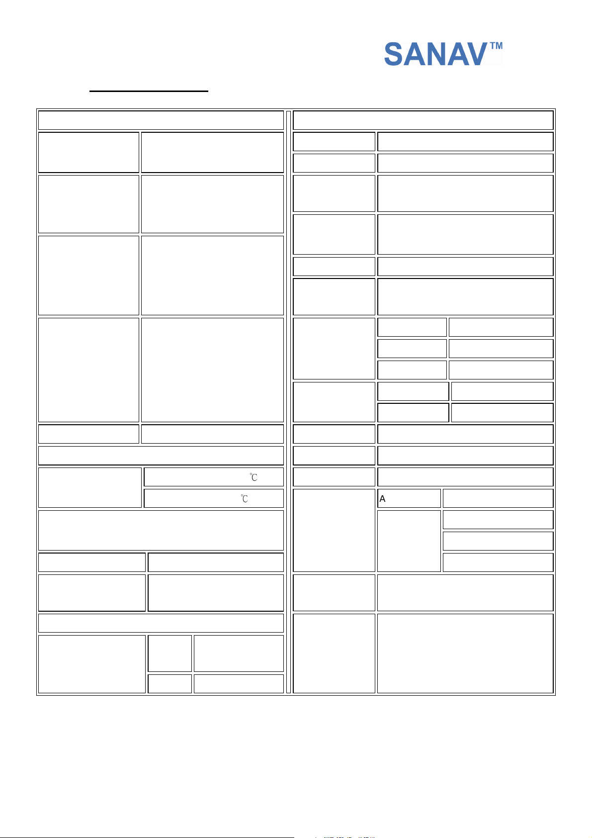
1.1 Specifications
PHYSICAL CONSTRUCTION
Dimension
Weight
RF Connector
Connector
L40.5mm*W35mm*H13.7mm
11 grams
Standard: MCX Jack
Optional: SMA, SMB Jack
12pin connector with 1.27mm
pitch
PERFORMANCE
GPS Chipset MTK-3301
Sensitivity -158dbm
Receiving
frequency
SBAS
DGPS RTCM Protocol
Receiver
architecture
Start-up time
Position accuracy
1575.42MHZ; C/A code
1 channel (Support WAAS, EGNOS,
MSAS)
32 parallel channels
Hot start
Warm start
Cold start
Without aid 3.3 m CEP
DGPS (RTCM) 2.6 m
1 sec. typical
35 sec. typical
41sec. typical
Construction
ENVIRONMENTAL CONDITIONS
Temperature
Protocol
Signal level Default: RS232
INTERFACE CAPABILITY
Standard Output
Sentences
Full EMI Shielding Velocity accuracy 0.1 Knot RMS steady state
Operating: -30 ~ +80
Storage: -40 ~ +85 ℃
NMEA V3.01
Option: UART @ 2.8V
Default
VTG, GSA*5
Optional GLL, ZDA
℃
Update Rate
Power Supply
Power
Consumption
External Antenna
Baud Rate
1 ~ 5Hz
3.3~5V +- 5%
Acquisition 65mA
Tracking
GPS antenna with 2.8V power input
4800 bps (default) &
4800/9600/38400/57600/115200 bps
are adjustable
50mA
(first 5 minutes)
48mA
(after 5 minutes)
41mA
(after 20 minutes)
COMMUNICATION
4
Chapter 2 Pin Assignment
2.1 Pin Assignment
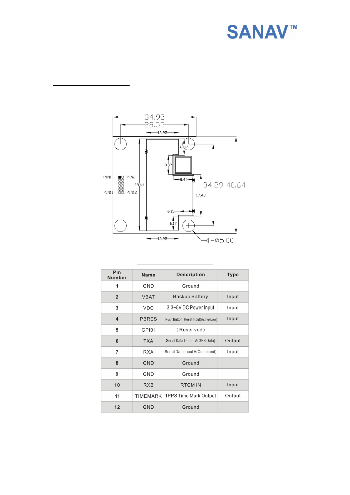
Figure 2.1 shows the pin definitions of FV-M7. Table 2.1 describes the corresponding
definitions for pins.
Figure 2.1 FV-M7 Pin definitions
5

2.2 Pin description
VIN (DC power input):
This is the main DC supply for a 3.3V ~ 5V +- 5% DC input power module board.
BATTERY (Backup battery):
This is the battery backup input that powers the SRAM and RTC when main power is removed.
Typical current draw is <10uA. Without an external backup battery, the module/engine board
will execute a cold star after every turn on. To achieve the faster start-up offered by a hot or
warm start, a battery backup must be connected. The battery voltage should be between
2.0v and 5.0v.
TIMEMARK (1PPS):
User can use this pin for special function.
For example, on/off LED
Output TTL level, 0V ~ 2.8V, 1PPS timemark output
TXA:
This is the main transmits channel for outputting navigation and measurement data to user’s
navigation software or user written software.
Output RS-232 level, 0V ~ 6V or Output TTL level, 0V ~ 2.8V
RXA:
This is the main receive channel for receiving software commands to the engine board from
MiniGPS or GPS Locator Utility (SV-3301) software or from user written software.
Input RS-232 level, 0V ~ 6V or Input TTL level, 0V ~ 2.8V
GND:
GND provides the ground for the engine board. Connect all grounds.
RXB:
This is mainly used to receive RTCM signals for differential purpose. Please note that a MTK
command must be sent to open this port first so that the RXB will receive the RTMC properly.
Input RS-232 level, 0V ~ 6V or Input TTL level, 0V ~ 2.8V
PBRES:
This pin provides active-low reset input to the GPS receiver module. It makes the GPS
receiver module to reset and search the GPS again.
6

Chapter 3 Operating GPS Locator Utility
GPS Locator Utility V2.61 is the latest utility for configuring the GPS settings of
Sanav GPS receivers. You can find the utility in the CD (FV-M7\Utility\Setup) and the
password is in License.txt. Double click on the Setup.exe and follow the installation
procedures.
GPS Locator Utility (Version 2.61), an application program for FV-M7, enables
you to do the configurations on the unit. Below are instructions of how to work with
this software, with assumption that you have successfully installed GPS Locator
Utility.
Mini GPS is an utility from MTK. If the users would like to read 32-channel, change
update rate (1 ~5Hz) and baud rate, please use Mini GPS.
7
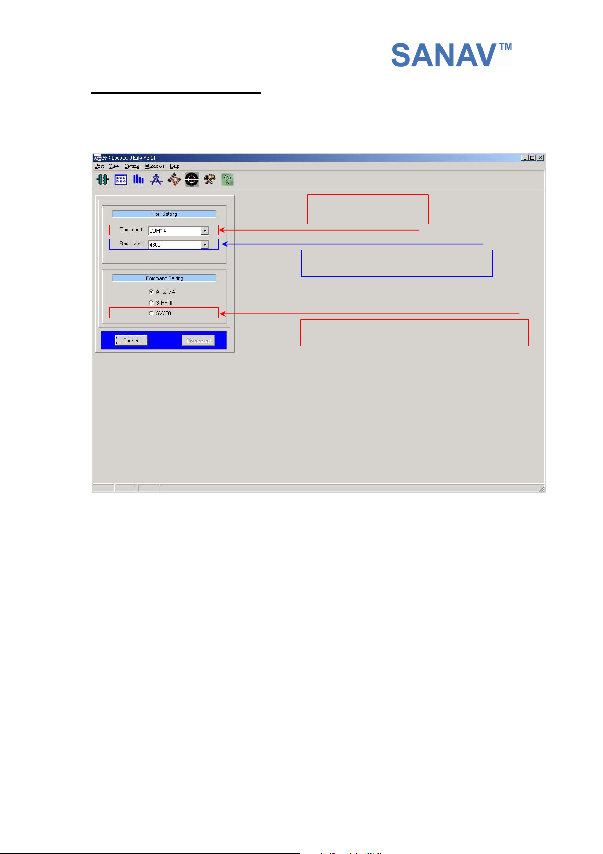
3.1 Connecting Com Port
After selecting the Com Port, bard rate and Command Setting, click on “Connect”
and you will be able to do the configurations.
Select baud rate (default of 4800)
Select SV3310, which is the same as MTK-3301
Select the ComPort
8
 Loading...