

Page 1
Commercial
Floor Machine
6000 Series
Owner’s Guide
Index
Important Safeguards ................. 2
General Information .................... 2
Grounding Instructions ............... 3
Operation/Accessories ............... 3
Remove From Carton ................. 4
Brush & Drive Block Installation .. 5
Adjustments ................................ 5
Controls ...................................... 6
Guidelines For Operation............ 6
Cord Storage .............................. 7
Clean Up And Storage ................ 7
Warranty ..................... Back Cover
For location of nearest
Eureka Warranty Station
or service information call
1-800-800-8975.
*En Mexico llame al 5670-6169.
Please Retain
We suggest you record the model, type and serial numbers
below. They are located on the silver rating plate on your
cleaner. For prompt and complete service information, always
refer to these numbers when inquiring about service.
Model & Type___________________________
Serial No. ______________________
It is also important to keep your receipt as proof of date of
purchase.
Page 2

IMPORTANT SAFEGUARDS
When using an electrical appliance, basic precautions should always be followed, including the following:
READ ALL INSTRUCTIONS BEFORE USING THIS VACUUM CLEANER.
WARNING
To reduce the risk of fire, electric shock, or injury:
Your machine is equipped with a safety switch lock and
•
power switch triggers designed for your safety. Do not
attempt to bypass or defeat the safety switch lock. Never
use any device to lock the power switch triggers in the
“ON” position.
Do not leave the floor machine when plugged in. Turn off
•
the switch and unplug the electrical cord when not in use
and before servicing or changing the brushes or pads.
Do not allow the machine to be used as a toy. Close
•
attention is necessary when used near children. Do not
leave the machine connected to an electrical outlet
unattended.
Use only as described in this manual. Use only
•
manufacturer’s recommended attachments.
Do not use with a damaged cord or plug. If the machine is
•
not working as it should, has been dropped, damaged, or
left outdoors return it to a service center before using.
Use care to keep the electrical supply cord from contacting
•
the rotating brush or drive block.
• Do not pull, close a door on, or pull the cord around sharp
edges or corners. Keep the cord away from heated surfaces.
Connect to properly grounded (3-wire) outlet only refer to
•
Grounding Instructions, Pg 3.
Do not use extensions cords or outlets with inadequate
•
current carrying capacity.
Turn off all controls before unplugging.
•
Do not unplug by pulling on cord. To unplug, grasp the
•
plug, not the cord.
Do not handle the plug or floor machine with wet hands.
•
Wind the cord no tighter than is necessary to retain it during
•
storage. Refer to Cord Storage, Page 7.
Use extra care when working near stairs.
•
Do not use in conjunction with flammable or combustible
•
liquids such as gasoline, or use in areas where explosive
vapor or dust may be present.
Store your floor machine indoors in a cool, dry area.
•
Keep your work area well lighted.
•
Warning - To avoid electrical shock, use indoors only.
•
SAVE THESE INSTRUCTIONS
GENERAL INFORMATION
Use the cleaner to pick up dirt and dust particles. Avoid picking
up hard or sharp objects that could damage the vacuum
cleaner.
Service Information
The instructions in this booklet serve as a guide to routine
maintenance. For additional service information, telephone
our toll free number for the nearest Eureka Authorized
Warranty Station. You should know the model, type and
serial number or date code when you call:
USA: 1-800-800-8975 Mexico: 5670-6169
Canada: 1-800-282-2886
If you prefer, you can write to The Eureka Company, Service
Division, 807 North Main St., Bloomington, Illinois 61701, USA.
In Canada, write to The Eureka Company, 866 Langs Drive,
Cambridge, Ontario N3H 2N7. Refer to The Eureka Warranty
for complete service information.
DO NOT OIL the motor or the brush drive. The
motor and brush drive are permanently sealed
and lubricated.
2
Page 3
Grounding Instructions
This appliance must be grounded. If it should malfunction or
breakdown, grounding provides a path of least resistance for
electric current to reduce the risk of electric shock. This
appliance is equipped with a cord having an equipmentgrounding conductor and grounding plug. The plug must be
plugged into an appropriate outlet that is properly installed
and grounded in accordance with all local codes and
ordinances.
DANGER
Improper connection of an equipment-grounding conductor
can result in risk of electric shock. Check with a qualified
electrician or service person if you are in doubt as to whether
the outlet is properly grounded. Do not modify the plug provided
with the appliance. If it will not fit the outlet, have proper outlet
installed by a qualified technician.
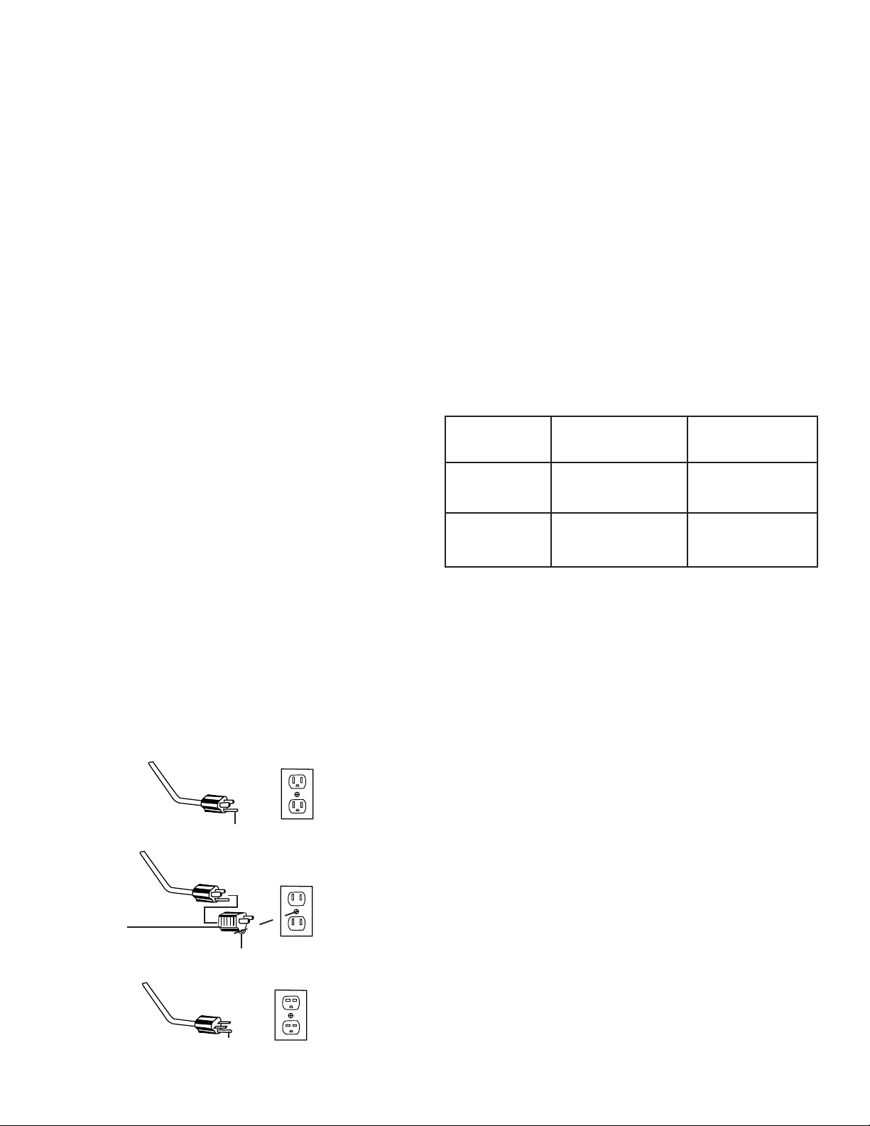
This appliance is for use on a nominal 120 volt circuit and has
a grounding plug that looks like the plug illustrated in Figure
1. A temporary adapter which looks like the adapter illustrated
in Figure 2 may be used to connect this plug to a two-pole
receptacle, as shown, if a properly grounded outlet is not
available. The temporary adapter should be used only until a
properly grounded outlet, Figure 1, can be installed by a
qualified electrician. The green colored rigid ear, lug, or the
like extending from the adapter must be connected to a
permanent ground such as a properly grounded outlet box
cover. Whenever the adapter is used, it must be held in place
by a metal screw.
OPERATION/ACCESSORIES
Choosing the Right Brush and Drive Block
Your floor machine is packed complete and ready for use after
you install a brush or drive block. (Brushes and pads are not
provided with the unit but are available at an additional cost.)
Your floor machine is designed to be used for many different
floor care applications. Make sure you use the correct brush
or pad for the type of job you want to perform. (Accessories
are available from the dealer from whom the floor machine
was purchased.)
When ordering brushes or drive blocks, refer to this chart and
specify correct brush or block diameter when ordering.
MACHINE SIZE BRUSH DIAMETER BLOCK DIAMETER
17” 17” 15”
20” 20” 18”
For floor finishing machines rated 150-250 volts:
If the machine is provided with an attachment plug cap as
shown in Fig. 3, it is intended for use on a 240 volt (nominal)
circuit. No adapter is available for this application.
NOTE: In Canada, the use of a temporary adapter is not
permitted by the Canadian Electrical Code.
GROUNDED
OUTLET BOX
FIGURE 1
Plug Grounding Pin
Adapter
Metal Screw
Grounding Tab
FIGURE 2
Plug Grounding Pin
FIGURE 3
3
Page 4

HOW TO REMOVE POLISHER FROM SHIPPING CRATE
1. Lift up on handle to
release lock.
4. Lift upper handle and
place end-to-end against
lower handle, lining up the
holes for the bolts. Slide
handle sleeve downward
until all holes are lined up.
2. Move upper handle forward to expose
wing nuts and angle bracket.
5. Use a screwdriver to line up
holes and guide bolts through
the handle.
3. Remove the wing nuts
and bolts from both
upper and lower handle.
Discard the angle
bracket.
6. Handle sleeve and bolts
will look like this when they
are properly installed.
7. Attach lock nuts on bolts and
fasten tightly.
4
8. Remove wing nuts and washers to
unfasten wood shipping retainer.
Discard wood shipping retainer.
9. Secure the handle release lock. Tip
the side of the carton where the
wheels are located on its side and
roll the machine out of the carton.
Page 5

BRUSH AND PAD DRIVER
INSTALLATION
ADJUSTMENTS
CAUTION: Disconnect the power cord from the electrical
outlet before installing a brush or pad driver.
ON
Fig. 4
To install a brush or pad driver, leave the handle in the upright
position and tip the machine backwards so it rests on its wheels
and upper handle section (Fig. 4). The brush and pad driver
both attach in the same manner: align the cutouts on the inner
ring of the brush or pad driver with the tabs on the inside of
the ring of the drive hub (Fig. 5). Push the brush or pad driver
firmly in position, then turn it counterclockwise until it locks
into place.
OFF
DRIVE BELT ADJUSTMENT
(Model 20” 1500 rpm 1.5 HP only)
CAUTION: Disconnect the power cord from the electrical
outlet before adjusting drive belt tension.
1. Loosen the bolts holding the drive motor to the frame; do
not remove (Fig. 6).
2. Turn the two screws at the rear of the frame until the belt
is tight.
3. Test the machine. If belt slips, adjust further. Retest. If
the belt does not slip, tighten the drive motor bolts. DO
NOT overtighten the drive belt.
To remove, turn the brush or pad driver clockwise until it stops,
then lift it off. Note: Always remove the brush or pad driver
when the machine is not in use.
CAUTION: Disconnect
the power cord from the
electrical outlet before
installing a brush or pad
driver.
Fig. 5
PAD CENTERING LOCK (Model 20” 1500 rpm 1.5
HP only)
To install a pad, tip the machine backwards so it rests on
the rear wheels and handle. After centering the pad on the
pad holder, insert the Pad Centering Lock and twist it
clockwise until it securely locks in place. To remove twist the
lock counterclockwise.
Adjusting Bolts
Fig. 6
HANDLE ADJUSTMENT
The handle can be adjusted to any desired work position by
simply pushing up on the handle lock (Fig. 7). Move the
handle to the desired position, then firmly push down on the
handle lock which will lock the handle in position.
Unlock
Lock
Fig. 7
5
Page 6

ADJUSTMENTS (Continued)
HANDLE CAM LOCK ADJUSTMENT
With the handle cam lock in the “up” position (unlocked), tighten
the adjusting nuts until there is a slight drag when the handle
is raised or lowered. The tube should be locked securely when
the handle lock is pressed downward (Fig. 8).
Adjusting Nuts
Fig. 8
CONTROLS
ON/OFF POWER SWITCH TRIGGERS
The ON/OFF switch is conveniently located in the form of
dual triggers underneath the handle grips.
To stop the machine, simply release the triggers. The safety
switch lock will automatically return to the engaged position.
USING THE 20” 175/300 rpm 2-speed FOR
BUFFING (Models SC6030, SC6035)
The model 20” 175/300 2-speed is a two-speed floor machine
designed for dual operation, scrubbing or buffing. A toggle
switch on the left side of the switch box selects the output
speed, 175 rpm for scrubbing or 300 rpm for buffing. Do not
operate this floor machine for buffing in low speed, it will not
do an effective job and tends to overload the motor
unnecessarily.
GUIDELINES FOR OPERATION
Your floor machine is a very sensitive, powerful unit. When
•
in operation, it should be guided gradually and smoothly
without sudden or rough motions. You will want to practice
with your machine on a smooth surface first until you have
experience in operating it.
• For ease of operation, always keep the brush or pad surface
level, balanced and flat on the floor at all times.
• Always adjust the operating handle to a comfortable height
at which the brush or pad surface is balanced before starting
the machine.
(see “Handle Adjustment” Page 5)
TO TURN THE MACHINE ON
The operating handle must be lowered to the operating position
before switching the machine ON. Place both hands firmly on
the handle grips with your fingers around the power triggers.
Do not apply pressure on the triggers before the safety switch
lock is disengaged.
Disengage the safety switch lock by pushing it forward with
one thumb. Then, while holding the safety switch lock in
disengaged position, squeeze the power triggers toward the
handle grips and return your thumb to the handle grip.
Push forward to disengage safety
switch lock.
• Your floor machine will operate differently on various
surfaces. For example, there will be much more resistance
when the machine is used with a brush on carpeted
surfaces than when it is used with a pad on a smooth
surface. The operator should be prepared to adjust for these
differences.
• BEGIN OPERATING THE FLOOR MACHINE WITH THE
BRUSH OR PAD SURFACE LEVEL, BALANCED AND
FLAT ON THE FLOOR.
• To move the machine to the right, slowly apply slight upward
pressure on the handle.
• To move the machine to the left, slowly apply slight
downward pressure on the handle.
• To move the machine forward or backward, keep brush or
pad flat on the floor and push or pull machine in the desired
direction.
DO NOT LET THE MACHINE REST ON THE PAD OR BRUSH
FOR AN EXTENDED PERIOD OF TIME. This may alter the
shape of the pad or brush which may cause the machine to
wobble.
6
Page 7

CORD STORAGE
When not in use, loosely wind the power cord around the
cord storage hook on the handle shaft and both of the handle
grips, as shown.
CLEAN UP AND STORAGE
After being used, your floor machine can be wiped clean with
a soft, damp cloth and should be stored in a clean, dry place.
7
Page 8

EUREKA SANITAIRE COMMERICAL EQUIPMENT LIMITED WARRANTY
Floor Machines / Air Movers
Excludes Vacuums
Your equipment which has been manufactured, tested and inspected in accordance with carefully specified engineering requirements
is warranted to be free from defects in material and workmanship. This Limited Warranty is, however, subject to the following qualifications,
conditions and limitations which are set forth to provide you and all users of the equipment with information concerning the duration,
extent, availability and applicability of the Limited Warranty, the procedure to be taken to obtain its performance, and other information
concerning the Limited Warranty policy.
The Limited Warranty is extended to the original end user as follows:
Machines: 3 years parts replacement and 1 year service labor warranty.
Replacement parts guaranteed for 90 days from date of installation against defects in material and workmanship.
This Limited Warranty will not cover damage attributable to the following:
(1) Improper, unreasonable or negligent use or abuse of the equipment.
(2) Use of equipment with hot water or high temperature above 130 degrees Fahrenheit (Solution Tanks)
(3) Abrasions or punctures of the equipment.
The start date of the Limited Warranty coverage shall be the purchase date of the original end user or six months from the date the
machine was shipped from the Factory, whichever comes first.
PARTS OF EQUIPMENT NOT COVERED BY THE LIMITED WARRANTY
Certain parts of equipment require replacement in the ordinary course of use due to normal wear by reason of their characteristics.
Normal wear items such as cords, switches, bumpers, carbon brushes, handle grips, belts, bearings, etc. are excluded from the Limited
Warranty.
EXCEPTIONS AND EXCLUSIONS FROM THE LIMITED WARRANTY
This equipment is required to be used on electric current as indicated on the data plate. Otherwise damage, defects, malfunctions or
other failure of the equipment arising from use on electric current not as indicated are excepted and excluded from this Limited Warranty.
Defects, malfunctions, failure or damage of the equipment caused by improper, unreasonable or neglect use or abuse while in possession
of the purchaser are likewise excluded from this warranty. If repair is done on your equipment by anyone other than those designated
as an authorized Warranty Center, THE MANUFACTURER at its sole option, may determine that this warranty will not apply and the
reimbursement for such repair will not be made.
PROCEDURE TO BE TAKEN TO OBTAIN PERFORMANCE OF LIMITED WARRANTY REPAIR
To secure repair of the equipment or any warranted parts under this Limited Warranty, the following procedure should be taken. The
inoperative equipment or warranted parts, together with satisfactory evidence of the purchase date, must be delivered, with shipping
and delivery changes prepaid, to one of the following:
(1) the dealer from whom purchased; or
(2) any authorized service station.
If you are unable to locate any of the foregoing, you may write or otherwise communicate to THE MANUFACTURER before repair
service is performed by anyone else. In such event, THE MANUFACTURER will provide either the location of a closely available
authorized distributor service department, authorized service station or other factory instructions. Upon compliance with the above
procedure, all warranted defects will be repaired, at no additional charge or costs to the customer and the repaired product returned to
the customer, with all shipping and delivery charges prepaid. In following the procedures set forth, PLEASE MAKE CERTAIN to state
the model, type and serial number as shown on the data plate of the equipment.
REPLACEMENT
In the event of a defect, malfunction or failure of your equipment or any warranted part to conform with this warranty, THE MANUFACTURER
may, at its sole option and own expense, replace the equipment or any warranted part with another new identical or reasonably
equivalent model or part in lieu of repairing the defect.
NO REFUND OF PURCHASE PRICE
THE MANUFACTURER will not, as a matter of its Limited Warranty policy, refund the customer’s purchase price.
Be certain that the Warranty S tation is “Eur eka/Sanitaire Authorized.” For the location of the near est Eureka/Sanitaire Authorized S tation or
for service information, see us at www.sanitairevac.com or telephone toll free: 1-800-800-8975.
©2003 White Consolidated, Ltd.
Part No. 73416
(09/03)
Printed in U.S.A.
 Loading...