

Sanitag Technologies AT004H, AT00123H User Manual

Setting Up Devices & RF Netwowk
THIS DOCUMENT IS THE PROPERTY OF SANITAG COMPANY. IT MAY NOT BE COPIED AND REPRODUCED WITHOUT WRITTEN PERMISSION OF SANITAG
COMPANY. COPYRIGHT NOTICES MAY NOT BE REMOVED
SANITAG RTLS TECHNOLOGIES
Cumhuriyet Bulvarı No: 45/9 Pamuk Plaza - Pasaport, İzmir
Tel: +90 (232) 465 0002 Fax: +90 (232) 464 4408
www.sanitag.com
Healthcare - Real Time Location
System
(HRTLS)
SETTING UP DEVICES & RF NETWORK
V.200.15

Setting Up Devices & RF Netwowk
THIS DOCUMENT IS THE PROPERTY OF SANITAG COMPANY. IT MAY NOT BE COPIED AND REPRODUCED WITHOUT WRITTEN PERMISSION OF SANITAG
COMPANY. COPYRIGHT NOTICES MAY NOT BE REMOVED
CONTENT
1. SETTING UP DEVICES & RF NETWORK ..................................................................... 1-1
1.1. Safety .................................................................................................................. 1-1
1.2. Introduction .......................................................................................................... 1-1
1.1. Device Definitions ................................................................................................ 1-4
1.1.1. Sanitag AC-001-LAN (Wireless Router) ................................................... 1-4
1.1.2. Active RFID Room Level Reader (Sanitag Model No: AR-001-HLR) &
Active RFID Long Range Reader (Sanitag Model No: AR-002-HLR) ....... 1-5
1.1.3. Active RFID Tag for Patients (Sanitag Model No: AT-001-H) ................... 1-6
1.1.4. Active RFID Tag for New Born Babies (Sanitag Model No: AT-002-H) ..... 1-7
1.1.5. Active RFID Tag for Assets (Sanitag Model No: AT-003-H) ..................... 1-8
1.1.6. Active RFID Tag for New Staff/Doctors (Sanitag AT-004-H) ..................... 1-9
1.2. Configuration ..................................................................................................... 1-10
1.2.1. Service Manager Software ................................ ..................................... 1-10
1.2.2. Configuration of Sanitag AC-001-LAN Router ....................................... 1-10
1.2.3. Prepare/Configure Sanitag AC-001-LAN Router with Ethernet
interface ................................................................................................. 1-10
1.2.4. Prepare/Configure Sanitag AC-001-LAN Router for Com Port ............... 1-12
1.2.5. Prepare RF Network .............................................................................. 1-13
1.3. An Analogy on an Active Instance of the Location Provider ............................... 1-14
-i- V.200.15

Setting Up Devices & RF Netwowk
THIS DOCUMENT IS THE PROPERTY OF SANITAG COMPANY. IT MAY NOT BE COPIED AND REPRODUCED WITHOUT WRITTEN PERMISSION OF SANITAG
COMPANY. COPYRIGHT NOTICES MAY NOT BE REMOVED
1-1
Setting Up Devices & RF Netwowk
THIS DOCUMENT IS THE PROPERTY OF SANITAG COMPANY. IT MAY NOT BE COPIED AND REPRODUCED WITHOUT WRITTEN PERMISSION OF SANITAG
COMPANY. COPYRIGHT NOTICES MAY NOT BE REMOVED
1. SETTING UP DEVICES & RF NETWORK
Rest of the manual guides you through the steps necessary for setting up and configuring
your Sanitag devices. Please read this manual before system setup.
1.1. Safety
The device must be used solely with its original power adaptor. Please note that the
adapter is 110/220V AC
1.2. Introduction
Sanitag devices are based on 2.4GHZ IEEE 802.15.4 compliant RF wireless network. To
form a minimal 802.15.4 RF Network, you should have at least 1-Router, 1-Reader and
Mobile Devices.
Main coordinator (router) establishes a mesh network once it is installed. Each plugged
reader (receiver), attends this network automatically and relays data for the network. All
reader nodes cooperate in the distribution of data in the network.
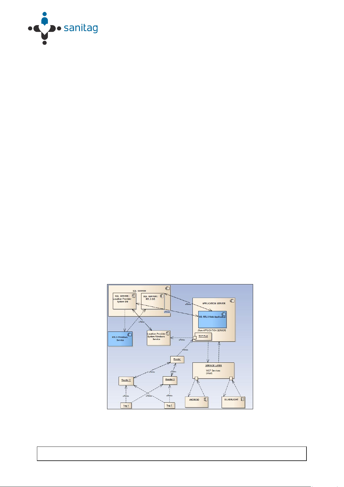
Sanitag’s small sized newborn baby tag is affixed to the ankle of the newborn infant to be
tracked. The tag contains an RF transmitter circuit. It transmits message signal,
comprising unique identity information, to receivers which are strategically placed within
the hospital. The message is propagated along a path by hopping from node to node until
it reaches the port wihch is being listened by the Location Provider Service software.
Location Provider Software calculates tags’ positions by using RSSI (received signal
strength indicator) levels, dimensions of the region to be tracked and fixed position
information of the receivers on that region.
Figure 1- Component Interoperability
1-1

Setting Up Devices & RF Netwowk
THIS DOCUMENT IS THE PROPERTY OF SANITAG COMPANY. IT MAY NOT BE COPIED AND REPRODUCED WITHOUT WRITTEN PERMISSION OF SANITAG
COMPANY. COPYRIGHT NOTICES MAY NOT BE REMOVED
Calculated positions are being written on the Location Provider System database. These
positions can also be used in real time by remoting technology. This architecture provides
flexiblity in integration with third party softwares. Sanitag H-RTLS application comprises
an independent service which listens the Location Provider System database. It
interpretes fetched information and applies some business rules on it prior to UI
interaction.
Tags comprise a conductive security element attachment having two ends, whose
electrical state will change when stretched, severed, or removed by parting the end.
When the electrical state changes an alarm code will be generated and sent to receivers.
This information will then be processed as explained above.
Built in motion sensor is able to detect unnatural movements like falling, being idle for a
certain period of time etc. Alarm will be generated as soon as this kind of movement is
detected.
1.3. RF affecting factors
All devices's RF signals can affect some material some extent. İf our devices's RF signal
encounter some material especially high-level obstacle severity material as stated in
Table 1. Router, Reader and Tags will be decreased range of distance. For this reason,
all device have to position as far as possible from especially obstruction of high level
obstacle severity material as in Table 1.
1-2

Setting Up Devices & RF Netwowk
THIS DOCUMENT IS THE PROPERTY OF SANITAG COMPANY. IT MAY NOT BE COPIED AND REPRODUCED WITHOUT WRITTEN PERMISSION OF SANITAG
COMPANY. COPYRIGHT NOTICES MAY NOT BE REMOVED
Obstruction
Obstacle
Severity
Sample Use
Wood / Wood paneling
Low
İnside a wall or hollow door
Drywall
Low
İnside Walls
Furniture
Low
Couches or office partitions
Clear glass
Low
Windows
Tinted glass
Medium
Windows
People
Medium
High-volume traffic areas that
have consirable pedestrian
traffic
Ceramic tile
Medium
Walls
Concrete blocks
Medium/High
Outer wall construction
Mirrors
High
Mirror or reflective glass
Metals
High
Metal office partitions, doors,
metal office furniture
Water
High
Aquariums, rain, fauntains
Table-1 RF Obstacles Found Indoors
1-3

Setting Up Devices & RF Netwowk
THIS DOCUMENT IS THE PROPERTY OF SANITAG COMPANY. IT MAY NOT BE COPIED AND REPRODUCED WITHOUT WRITTEN PERMISSION OF SANITAG
COMPANY. COPYRIGHT NOTICES MAY NOT BE REMOVED
1.1. Device Definitions
1.1.1. Sanitag AC-001-LAN (Wireless Router)
Router is hierarchically the top-most Node of 802.15.4 RF Network . It forms/manages RF
Network, collects all RF Network data and behaves as a gateway from RF Network to
upper media. There are two type of Router:
Router with Ethernet Interface: Redirects RF network traffic to a prederfined “IP:Port”
over ethernet via TCP/IP protocol.
Router with USB Virtual Com Port Interface: Redirects RF network traffic to Serial
Port.
Router device has blue leds on itself.
If leds blink, it means that the router device tries to form Rf network.
If leds lighten constantly, it means that the router device forms Rf Network
succesfully.
Sanitag AC-001-LAN device has RF propagation that 2.5 dBm output power level and it
has 2,4 GHz uFl tranmitter antenna which is has 2dBi gain.
Also, AC-00-H device has UWB module that has 3.1 ~ 8 GHz monopole antenna. We
operation at 4.4GHz due to special reason. UWB Module output power is fully adjustable
from 0 dBm to 15.5 dBm via firmware.
The antenna that using on Sanitag AC-001-LAN is wire antenna which is fixed on PCB,
That's why İt cannot change reorient and relocate.The device's antenna type is
omnidirectional. Therefore, the Sanitag AC-001-LAN can take signal every direction. If
Sanitag AC-001-LAN obstructs by obstacle of in Table 1. The device’s RF signal will
decrease as stated in Table 1.
THIS DEVICE COMPLIES WITH PART 15 OF THE FCC RULES. OPERATION IS
SUBJECT TO THE FOLLOWING TWO CONDITIONS.
(1) THIS DEVICE MAY NOT CAUSE HARMFUL INTERFERENCE, AND (2) THIS
DEVICE MUST ACCEPT ANY INTERFERENCE RECEIVED, INCLUDING
INTERFERENCE THAT MAY CAUSE UNDESIRED OPERATION.
Warning: Changes or modifications not expressly approved by the party responsible for
compliance could void the user’s authority to operate this equipment.
Note: This equipment has been tested and found to comply with the limits for a Class B
digital device, pursuant to part 15 of the FCC Rules. These limits are designed to provide
reasonable protection against harmful interference in a residential installation. This
equipment generates, uses and can radiate radio frequency energy and, if not installed
and used in accordance with the instructions, may cause harmful interference to radio
communications.However, there is no guarantee that interference will not occur in a
particular installation. If this equipment does cause harmful interference to radio or
television reception, which can be determined by turning the equipment off and on, the
1-4
 Loading...