

SaniServ A7081HEP Operation Manual
SaniServ
An AFFINIS GROUP Company
“Reliability from the team that Serves the Best”
®
Pressurized Frozen Beverage Dispenser
Model A7081HEP
Operation Manual
SaniServ P.O. Box 1089 Mooresville, Indiana 46158


Distributor Name: _____________________________ __________________________
Address: ___________________________________________ ___________________
Phone: ________________________________________________________________
Date of Installation: ________________________________ _____________________
Model Number: _________________________________________________________
Serial Number: _________________________________________________________
Installer/Service Technician: _____________________________________________
SERVICE: Always contact your SaniServ dealer or distributor for service questions or service
agency referral. If your SaniServ dealer or distributor cannot satisfy your service requirements,
he is authorized to contact the factory for resolution.
Note: It is the Owner’s responsibility to maintain the Service Record located on the inside rear
cover of this manual. An accurate record of service performed can greatly expedite
troubleshooting of problems and significantly reduce repair costs.
PARTS: Always order parts from your SaniServ dealer or distributor. When ordering
replacement parts, specify the part numbers, give the description of the part, the model number
and the serial number of the machine.
WARRANTY: Remove the Check Test Start (CTS) form and fill it out in its entirety. Return the
original (white) copy to SaniServ. The Dealer/Distributor retains the second (yellow) copy and
theOwner/Operator retains the third (pink) copy.
The Manufacturer's Limited Warranty is printed on the reverse side of the Owner/Operator copy.
IMPORTANT
TO VALIDATE THE WARRANTY, THE CTS FORM MUST BE COMPLETED AND RETURNED
TO THE FACTORY WITHIN 30 DAYS OF INSTALLATION.
Note: The Check Test Start function must be performed by a qualified technician.
WARRANTY INFORMATION
Introduction
This manual provides a description of the SaniServ Pressurized Frozen Beverage Dispenser. It has been prepared to
assist in the training of personnel on the proper installation, operation, and maintenance of the machin es.
Read and fully understand the instructions in this manual before attempting to install, operate, or perform routine
maintenance on the machines.
Initially, the following sections of the manual must be performed in sequence:
1. Installation 4. Operation
2. Installer's Preoperational Check 5. Disassembly & Cleaning
3. Initial Start-up Preparation 6. Assembly & Lubrication
Installation
1. Install the legs using the instructions on the shipping
carton.
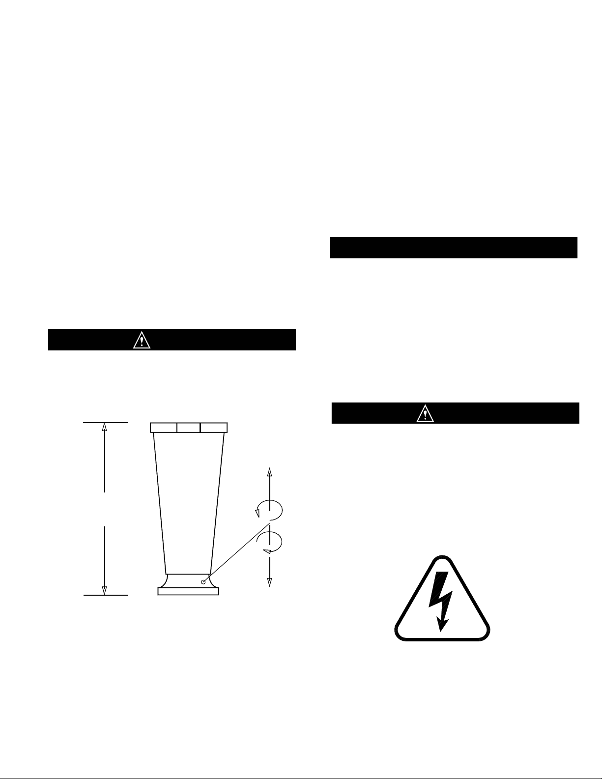
2. Place the machine in the desired location and level
the unit by turning the bottom part of each leg clockwise
or counterclockwise (Fig. 2). The machine MUST be
level to operate properly.
THESE UNITS MUST NOT BE OPERATED WITHOUT
WARNING
THE LEGS INSTALLED UNLESS THE MACHINE IS
SUPPLIED WITH A COUNTERTOP MOUNTING PAD
OR SEALED TO THE COUNTERTOP.
Minimum Clearance
3.
A minimum 6” (152 mm) clearance
must be maintained at
the rear and sides of the machine
for adequate ventilation.
4”(102 mm) for
Counter Top Models
Fig. 2
Leg Installation
IMPORTANT
4. Electrical and refrigeration specifications are located
on the data plate on the rear panel of the machine.
Consult local authorities for information regarding
plumbing and electrical codes in your area.
Insure that the unit is in the off position and plug it into a
115 volt, 15 amp or 20 amp receptacle.
Note: All SaniServ machines should have their own
dedicated circuits to prevent low voltage conditions
caused by other operating equipment.
WARNING
FAILURE TO PROVIDE FOR PROPER EARTH
GROUND ACCORDING TO LOCAL ELECTRICAL
CODES COULD RESULT IN SERIOUS ELECTRICAL
SHOCK OR DEATH. DO NOT USE EXTENSION
CORDS. INSTALL THE PROPER SIZE WIRE FOR
THE REQUIRED MACHINE AMPS. BE CERTAIN TO
OBSERVE LOCAL CODES IN SELECTING WIRE OR
CORD SIZE AND TYPE.
DO NOT TURN MACHINE ON UNTIL THE
INSTALLER’S PRE-OPERATIONAL CHECK
SECTION IS COMPLETE.
PAGE 1
INTRODUCTION and INSTALLATION
Installer’s Preoperational Check
THE FOLLOWING ITEMS MUST BE PERFORMED BEFORE ATTEMPTING TO OPERATE THE EQUIPMENT:
WARNING! HAZARDOUS MOVING PARTS. DO
NOT WEAR LOOSE FITTING CLOTHING. KEEP
HANDS, HAIR, AND CLOTHING AWAY FROM
MOVING INTERNAL PARTS.
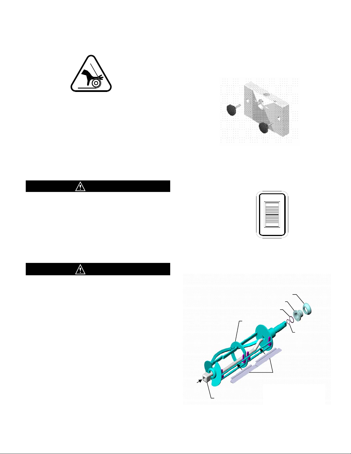
1. Remove the front plate (Fig. 1) by turning the black
plastic knobs in a counterclockwise direction.
After removing the knobs, pull the front plate off the
studs. Then grasp the front of the dasher assembly
(Fig.3) and remove it from the dispenser by pulling
it out slowly and straight so the scraper blades are
not damaged.
WARNING
Fig. 1
Front Plate
BEFORE PROCEEDING TO STEP 2, BE CERTAIN
THAT THE DASHER HAS BEEN REMOVED
2. Set the Auto/Clean switch (Fig. 2) to th e “AUTO”
position. Doing so allows the compressor and
dasher motor to start. Check to see that the
refrigeration system is operating by feeling the
inside of the freezing cylinder. It should turn cold
CAUTION
UNDER NO CIRCUMSTANCES SHOULD THE UNIT
BE OPERATED IN THE “AUTO” POSITION FOR
MORE THAN THREE MINUTES WITH EMPTY
FREEZING CYLINDERS . DOING SO WILL RESULT
IN DAMAGE TO THE MACHINE
within one minute.
3. Set the Auto/Clean switch to the “OFF” position.
4. Install the Dasher Assembly (Fig. 3) inserting it in
the freezing cylinder and pushing toward the rear of
the cylinder while rotating the assembly until it seats
into the drive at the rear of the cylinder.
5. Install Front Plate Assembly and secure with the
black knobs (Fig. 1).
Rear Bearing O-Ring
Stator Rod
AUTO
OF
F
CLEANOUT
OF
F
Fig. 2
Auto/Clean Switch
Rear Seal
Rear Bearing
Dasher
Scraper
Fig. 3
Dasher Assembly
Dasher O-Ring
INSTALLERS PREOPERATIONAL CHECK
PAGE 2

1. Connect the regulator to an approved CO2 cylinder and
connect to the CO2 port on the "smart coupler".
2. Turn the "smart coupler" to the "OFF" position.
3. Set the CO2 regulator to 12-13 psig.
4. Prepare a 5 gallon container of brewery approved beer line
cleaning solution and connect to the "smart coupler".
5. Turn the coupler lever to the "CLEAN" position.
6. Fill the freezing cylinder until the amber light goes out.
7. Lift up on the Pressure Relief Plug (Fig. 4) to vent air from
the freezing cylinder. When solution discharges from the
bottom of the Pressure Relief Plug, close by pushing
downward on the plug.
8. When the amber light goes out again, turn the "Auto/
Cleanout" switch to the "CLEAN" position and allow the
machine to run for approximately 3 minutes.
9. Turn the machine to "OFF" and drain cleaning solution by
opening spigot and Pressure Relief Plug. Close plunger
and plug when machine is drained.
10. Repeat steps 4 through 9 using fresh potable water and
drain.
Initial Startup Preparation
Operation
Fig. 4
Pressure Relief Plug
1. With machine in "OFF" position, connect keg of product and fill cylinder until amber light goes off.
2. Allow any foam to settle and vent barrel by lifting up on the pressure relief plug. Close Pressure Relief Plug.
3. Turn "Auto/Cleanout" to the "AUTO" position.
4. When the machine cycles off, draw a sample of product and check for proper consistency. Repeat this step two
times.
5. If the product is too soft or two stiff, refer to the section on consistency adjustment.
Disassembly and Cleaning
CONSULT YOUR LOCAL HEALTH AGENCY FOR LOCAL CLEANING AND SANITIZING REQUIREMENTS.
This unit does not come pre-sanitized from the factory. Before serving product, the dispenser must be disassembled,
cleaned, lubricated, and sanitized. Please be aware that these instructions are general guidelines. Cleaning and sanitizing
procedures must conform to local Health Authority requirements.
Emptying Machine
Prior to the disassembly and cleaning of parts, the machine must be emptied of product. Use the following
Procedures. If this is first time operation, disregard these steps.
1. Set the Auto/Clean switch to the “CLEANOUT” position and dispense all product from the freezing cylinder by
pulling downward on the spigot handle to empty the machine.
2. Set the Auto/Clean switch to the “OFF” (center) position. Close the spigot handle before proceeding to cleaning.
DO NOT INSERT ANY OBJECTS OR TOOLS FRONT PLATE DISPENSING HOLE WHILE THE MACHINE IS
RUNNING. DAMAGE TO THE MACHINE OR PERSONAL INJURY MAY RESULT
PAGE 3
DISASSEMBLY and CLEANING
 Loading...