

Sangoma Vega 100G, Vega 200G, Vega 5000, Vega 400G, Vega 50 Analog Hardware Installation
...Page 1
Hardware Installation
Unboxing
When opening up your Vega Gateway packaging, carefully inspect the components for any signs of damage due to shipping.
If you notice any damaged components please contact your point of purchase and indicate the issue.
Do not continue to install your Vega Gateway if any of your components are damaged.
What's In the Box
Your Package should contain the following items:
Vega 100G/200G
1 Vega VoIP Gateway Appliance
2 E1/T1 RJ45 CAT5 cables (Red colour)
2 LAN Cables (Yellow colour)
1 RJ45-USB Console Cable (light blue colour)
mounting feet
External Power brick
AC power Cord (Country specific)
Quick Start Guide
Warranty and License Information
Vega 400G
1 Vega 400G VoIP Gateway Appliance
4 E1/T1 RJ45 CAT5 cables (Red colour)
2 LAN Cables (Yellow colour)
1 RJ45-USB Console Cable (light blue colour)
2 Mounting brackets
Power Cord (Country specific)
Quick Start Guide
Warranty and License Information
Vega 50 Analog
1 Vega 50 VoIP Gateway Appliance
Vega 50 Analog
4-8 Yellow Analog cables (amount dependent on number of analog ports)
2 LAN Cables (Yellow colour)
1 RJ45-to-serial Console Cable
2 Mounting brackets
External Power brick
AC power Cord (Country specific)
Quick Start Guide
Warranty and License Information
Vega 50 BRI
Page 2

1 Vega 50 VoIP Gateway Appliance
Vega 50 BRI
4 BRI Cables
2 LAN Cables (Yellow colour)
1 RJ45-to-serial Console Cable
2 Mounting brackets
External Power brick
AC power Cord (Country specific)
Quick Start Guide
Warranty and License Information
Vega 5000
1 Vega 5000 VoIP Gateway Appliance
2 LAN Cables (Yellow colour)
1 RJ45-to-serial Console Cable
2 Mounting brackets
AC power Cord (Country specific)
Quick Start Guide
Warranty and License Information
Vega 3000G
1 Vega 3000 VoIP Gateway Appliance
1 LAN Cables (Yellow colour)
1 RJ45-to-usb Console Cable
2 Mounting brackets
DC External Power Brick
AC power Cord (Country specific)
Quick Start Guide
Warranty and License Information
Vega 3050G
1 Vega 3050 VoIP Gateway Appliance
1 LAN Cables (Yellow colour)
1 RJ45-to-usb Console Cable
2 Mounting brackets
AC power Cord (Country specific)
Quick Start Guide
Warranty and License Information
Vega 60G
1 Vega 60 VoIP Gateway Appliance
1 LAN Cables (Yellow colour)
1 RJ45-to-usb Console Cable
2 Mounting brackets
AC/DC External Power adaptor and power cord (country specific)
Quick Start Guide
Warranty and License Information
Vega 4 x 4
1 Vega 4 x 4 VoIP Gateway Appliance
2 LAN Cables (Yellow colour)
1 RJ45-to-usb Console Cable
2 Mounting brackets
AC power Cord (Country specific)
Quick Start Guide
Warranty and License Information
NOTE: Module(s) Sold Separately
Accessories
FXO Plug-In Module (for Vega 3050G)
1 FXO Plug-In Module (provides 2 FXO ports)
1 replacement cover plate with cut-out
Quick Start Guide
Page 3
Component Overview
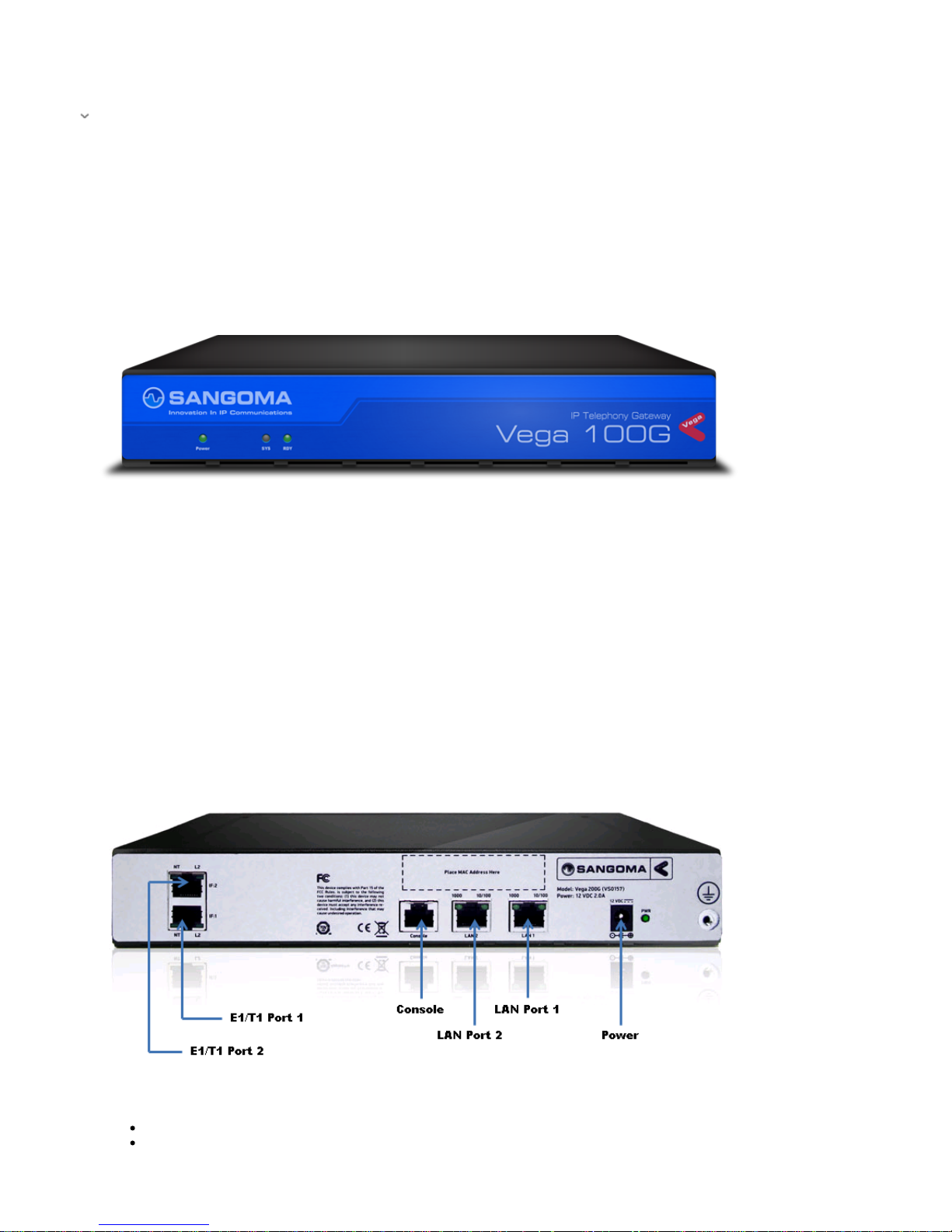
Vega 100G
Front Panel of Vega 100G
Back Panel of Vega 100G
Power - DC Power connector.
E1/T1 Port 1-2 - RJ45 port used to connect your E1/T1 Cable
Page 4
LAN Port 1/LAN Port 2 - RJ45 ports used to connect your LAN cables. These are Gigabit compatible ports.
Console - Used for diagnostics. Console cable plugs into this port
Find Below the Default pinout configuration:
Port 1 (CPE/Te) Port 2 (NET/NT)
Pin Signal
1 RxRing
2 RxTIP
4 TxRing
5 TxTIP
Pin Signal
1 TxRing
2 TxTIP
4 RxRing
5 RxTIP
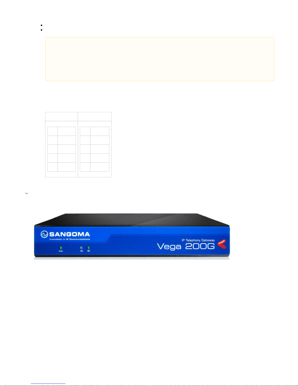
Vega 200G
Front Panel of Vega 200G
Back Panel of Vega 200G
Port 1 is configured for CPE/TE. This port is typically connected to Telco as it is set to receive the clock from the remote
side
Port 2 is configured for NET/NT. This port generating clock signal and is typical connected to another PBX
If you wish to change the configure of the ports (i.e. port 1:NET/NT or port 2: CPE/TE) you must connect a cross-over
cable. (there is no software configurable pin-switching)
Only one port can be used for VoIP (SIP<->TDM) as the license only allows for 30 VoIP sessions. However, you can use
both ports if you are doing TDM<->TDM applications
Page 5
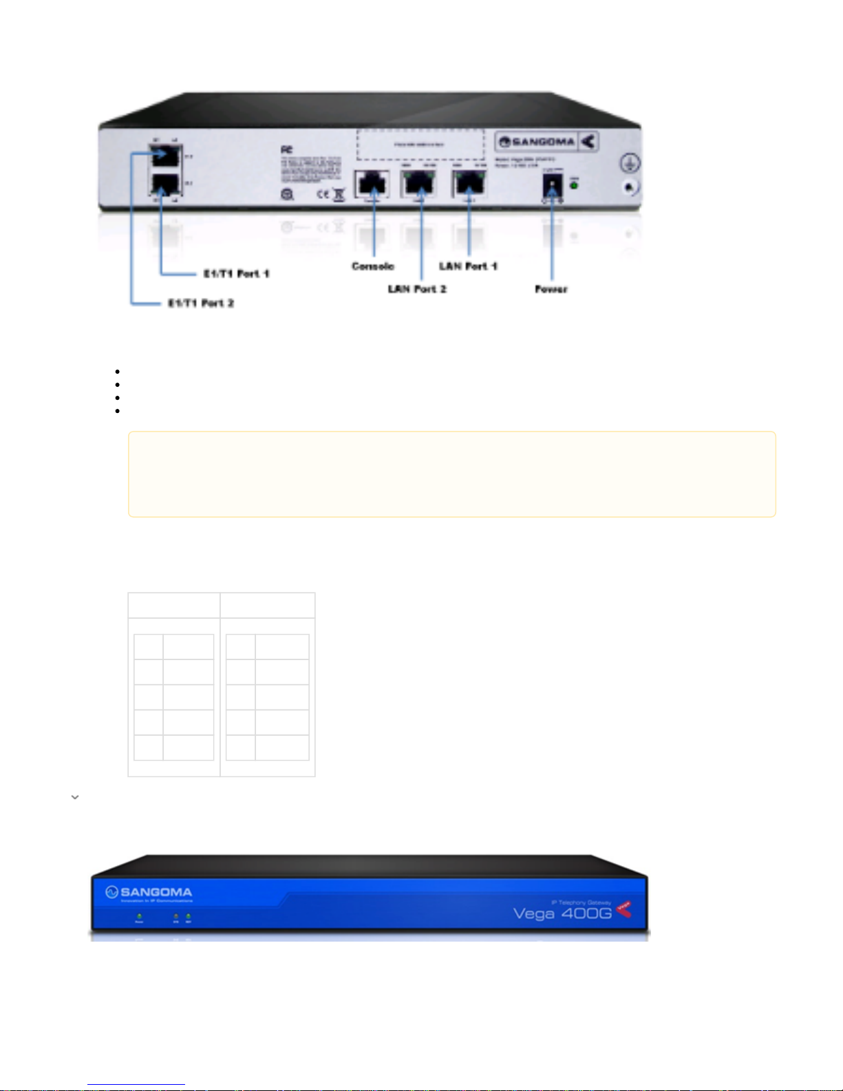
Power - DC Power connector.
E1/T1 Port 1-2 - RJ45 port used to connect your E1/T1 Cable
LAN Port 1/LAN Port 2 - RJ45 ports used to connect your LAN cables. These are Gigabit compatible ports.
Console - Used for diagnostics. Console cable plugs into this port
Find Below the Default pinout configuration:
Port 1 (CPE/Te) Port 2 (NET/NT)
Pin Signal
1 RxRing
2 RxTIP
4 TxRing
5 TxTIP
Pin Signal
1 TxRing
2 TxTIP
4 RxRing
5 RxTIP
Vega 400G
Front Panel of Vega 400G
Back Panel of Vega 400G
Port 1 is configured for CPE/TE. This port is typically connected to Telco as it is set to receive the clock from the remote
side
Port 2 is configured for NET/NT. This port generating clock signal and is typical connected to another PBX
If you wish to change the configure of the ports (i.e. port 1:NET/NT or port 2: CPE/TE) you must connect a cross-over
cable. (there is no software configurable pin-switching)
Page 6

AC Power - Power socket to be used with the AC Power cord provided with your Vega
Power Switch - Switch used to turn the Vega Gateway ON/OFF when power cord is plugged in
Port 1-4 - E1/T1 RJ45 ports used to connect E1/T1 cables. The 4 ports directly above these ports are only used for bypass mode
LAN 1/LAN 2 - RJ45 ports used to connect your LAN cables. These are Gigabit compatible ports.
Vega 50 Analog
Front Panel of Vega 50
Back Panel of Vega 50
Page 7

Analogue FXS / FXO Variants
Vega 50 BRI
Front Panel of Vega 50
Page 8

Power - DC Power connector.
Analog/BRI Ports - porst used to connect analog/bri cables
LAN 1/LAN 2 - RJ45 ports used to connect your LAN cables.
Console - Used for diagnostics. Console cable plugs into this port
Page 9

Vega 5000
Front Panel of Vega 5000
Back Panel of Vega 5000 (25 port)
Page 10

Power - AC Power socket..
Analog Ports - Am phenol RJ21 style connector with 25 analog ports.
LAN 1/LAN 2 - RJ45 ports used to connect your LAN cables.
Console - Used for diagnostics. Console cable plugs into this port
Analogue FXS / FXO Variants
Vega 3000G
Front Panel of Vega 3000
Page 11

Back Panel of Vega 3000 (24 port)
Power - AC Power socket..
Analog Ports - Am phenol RJ21 style connector with 24 analog ports.
LAN 1 - RJ45 ports used to connect your LAN cables. This is a Gigabit speed Lan port
Console - Used for diagnostics. Console cable plugs into this port
Vega 3050G
Front Panel of Vega 3050G
Back Panel of Vega 3050G (50 FXS port)
Page 12

From left to Right:
Power - AC Power socket.
FXS Ports 26-50 - Amphenol RJ21 style connector with 25 analog ports.
FXS Ports 1-25 - Amphenol RJ21 style connector with 25 analog ports.
FXO Ports 1-2 - FXO Plug In Module Sold Separately
Console - Used for diagnostics. Console cable plugs into this port
LAN Port - RJ45 ports used to connect your LAN cables. This is a Gigabit speed LAN port
Power LED- When lit unit is active
FXO Plug-In Module (for Vega 3050G)
-> Installation Guide
Vega 60G
Front Panel of Vega 60G
Back Panel of Vega 100G
Page 13

PSTN Interfaces: Protocol and density varies based on model
LAN Port- RJ45 port for LAN
USB Port- For Storage
Console - Used for diagnostics. Console cable plugs into this port
Power - DC Power connector.
Ground
Vega 4 x 4
Front Panel of Vega 4 x 4
Back Panel of Vega 4 x 4
Ground
Power - AC Power socket.
PSTN Interfaces: Protocol and density varies based on model Module(s) Inserted
Console - Used for diagnostics. Console cable plugs into this port
LAN Ports- RJ45 port for LAN
Power LED
NOTE: Module(s) Sold Separately
Page 14

Module Pinouts
PSTN interface connections are made via RJ45 connectors. The pin-out of the connector depends on the type of module fitted.
Pin FXSFXS FXOFXO FWIC GenGen
1
2
3 Rx
4 Tip Tip Tx Tx/Rx
5 Ring Ring Tx Tx/Rx
6 Rx
7
8
Hardware Installation
Placement
The Vega Gateway can be placed either table top or rack mounted
Table Top: Place Vega Gateway on flat level surface, away from moisture. Verify adequate ventilation to prevent unit from overheating.
Rack Mounting:
All Vega Gateways can be rack mounted. The packaging contents should include rack mounting brackets to be used when
mounting on a standard 19" rack unit.
Prerequisites:
Rack mounting bolts (not supplied) are required to mount the gateway + bracket assembly to the rack unit
Rack Mounting Guides:
Vega 60G
Ground
Once a location has been selected, properly ground the Vega Gateway using the ground lug located to the left of the power socket
Wiring Connection
Vega 50 / Vega 5000 / Vega 100/200/400G:
Connect one of the LAN cables (yellow ended) ,that came shipped in the box, to LAN 1 port. You may leave LAN 2 unconnected as it is
not typical used. (LAN 1 is configured to retrieve an IP address from DHCP)
Vega60G / Vega 3000G / Vega 3050G
Connect the Yellow LAN cable into the port labeled LAN, and the other end into your local network. The LAN port is configured to
retrieve an IP address from DHCP
Connect the PSTN cables,that came shipped in the box, to the PSTN ports. Connect as many PSTN ports as required.
Power Plug connection:
Vega 50 / Vega60G/ 100G / 200G / 3000G: Plug in the power cable to the external power brick/power socket, and the other end into the
power connector on the Vega
Vega 400G / Vega 5000, Vega 3050G: Plug in the power cable into the power socket located on the Vega gateway
There is no power switch on the Vega60G/Vega 100G/200G/Vega50/Vega3000G/Vega3050G. As soon as you connect power to the
unit it will power up. To switch off the Vega simply unplug the power cord.
Page 15

Accessories
FXO- Plug-In Module For Vega 3050G
-> Installation Guide
Proceed to the " " page now to being accessing the Vega Gateway WebGUI. Finding your IP address
The power LED on the front panel will illuminate.
LAN LEDs will also illuminate indicating 10/100 or 10/100/1000 (Gigabit) connection (depending on your Vega). The LAN LEDs are
duplicated on the front and rear of the Vega. The LEDs blink off to indicate LAN activity.
 Loading...