

Sangoma 3050G Installation Manual
FIELD UPGRADE
INSTALLATION MANUAL
3050G
FXO PLUG-IN
MODULE
4. FXO MODULE ACTIVATION
The following steps will guide you through the software process to activate the FXO
ports.
A) Log into your Vega 3050G webGUI by typing its IP address inside the URL of a
browser of your choice
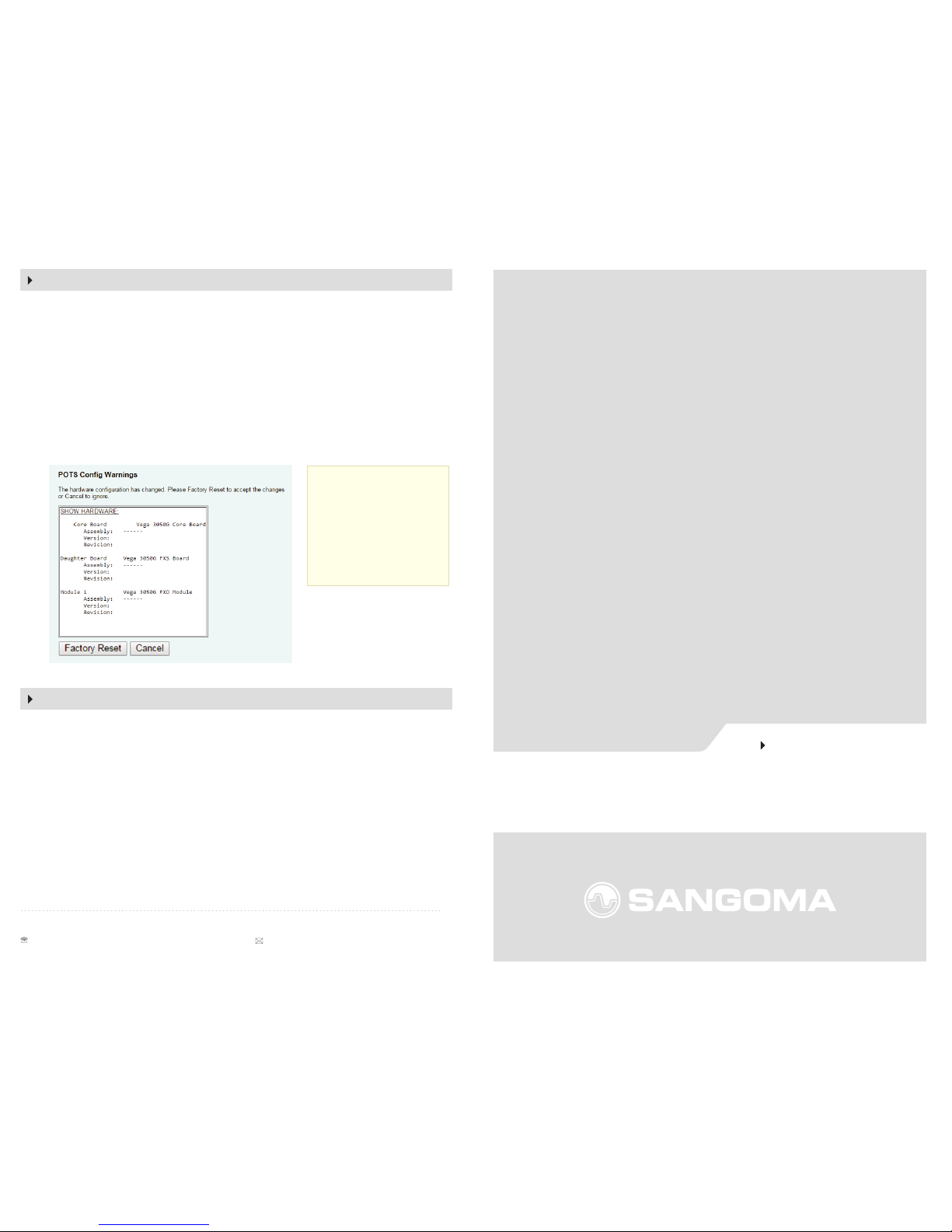
B) A window will pop up indicating there is a hardware change within the Vega.
This message is normal as the FXO plug-in module was added.
C) A factory reset of the Vega 3050G is required at this point to allow the unit to
fully detect the new FXO ports. Click the 'factory reset' button visible near the
bottom of the window (See Diagram below).
A) A restore of your conguration is now required. Navigate to ‘System >
Conguration and click Choose File where it says ‘Send File to Gateway’ . A
window will pop up allowing you to search for the backup you previously
created (if you did not alter the name of the backup it will be called ‘cong.txt’)
B) Once selected click the ‘Upload’ button which will restore the Vega to previous
conguration
C) You will be required to Apply and Save settings
With the Vega now ready, you may now congure the new FXO ports on your Vega
3050G. Navigate to POTS and congure the ports.
Sangoma.com © 2016 Sangoma Technologies Proprietary
100 Renfrew Drive, Suite 100, Markham ON L3R 9R6 Canada
+1 905 474 1990 or 1 800 388 2475 (toll free in N. America) sales@sangoma.com
5. RESTORE YOUR CONFIGURATION
Note: Save your
existing conguration if
you have not done so,
as described in Step 2.
If you do not perform a
back up, your existing
conguration will be
lost.
Thank you for purchasing the FXO Plug-In Module for your Vega 3050G.
The following steps will guide you through the physical installation of the
FXO-Plug-in module into the rear of the Vega 3050G as well as WebGUI
re-conguration to activate.
Your packaging will include the following:
• 1 FXO Plug-In module
• 1 back plate
If any of the items are missing, please contact your reseller or point of purchase.
Note: For new Vega 3050G installations without any user conguration, you may
skip this step and move to step 3.
To save a backup of the current conguration navigate to ‘System > Conguration’
and click Download. A window will prompt you to save cong.txt to your local
system (this is the complete backup of your Vega 3050G).
Preparation
A) Power down the Vega Gateway and remove the power cord from the unit.
B) Place the Vega Gateway on a at surface with the rear of the unit facing
towards you
C) Verify the Vega Gateway is grounded.
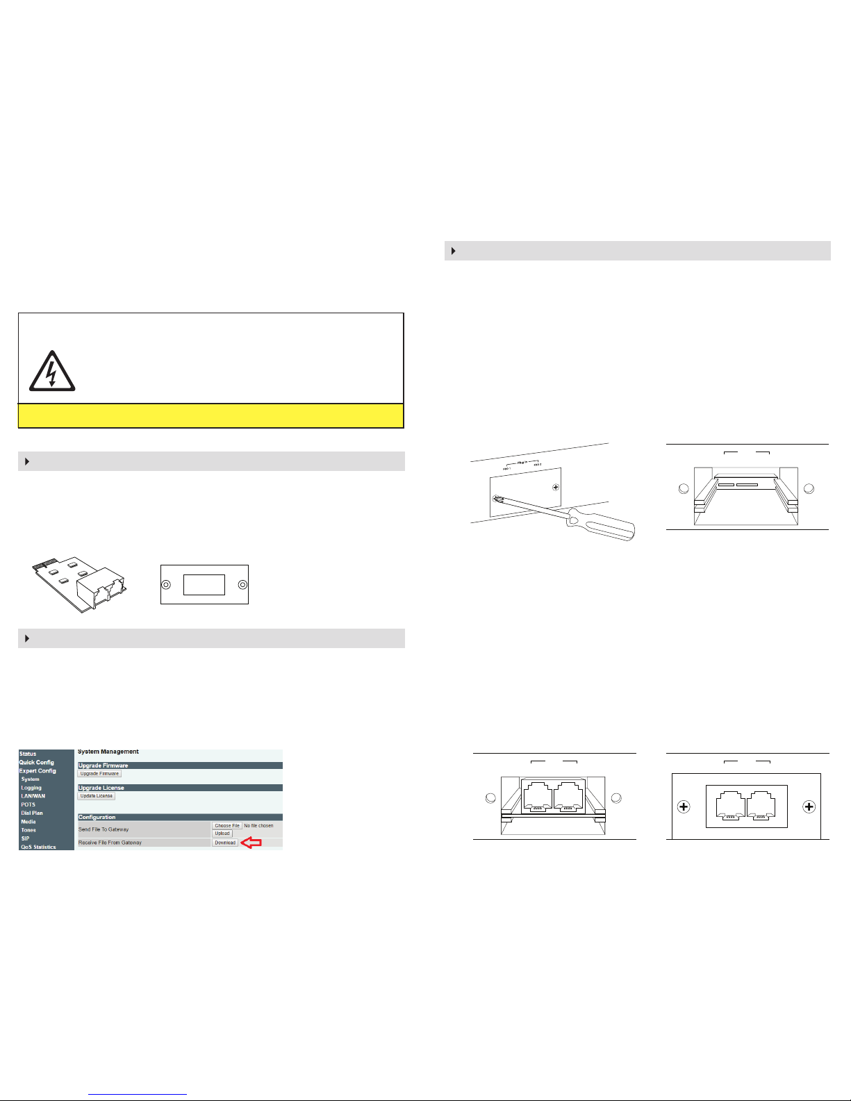
D) Using a screwdriver remove the screws holding the FXO back plate and
remove the FXO back plate as seen in the diagram 1.
Note: The screws will be re-used for the following step. The back-plate will no
longer be used and can be stored for safe keeping.
E) The Vega Gateway will now have the FXO cut-out exposed, as seen below in
Diagram 2.
Installation
A) Remove the FXO-Plug-In Module from its packaging and carefully insert into
the Vega Gateway’s FXO cut-out.
B) Carefully slide the FXO-plug-in Module into the Vega Gateway’s FXO cut-out
until it is rmly locked in place, as seen below in diagram 3. The RJ11
connectors should be facing towards you when installed with a small gap around.
C) Install the new back-plate connector, included in the packaging, directly over
the FXO ports and lining up the holes with the mounting holes on the Vega
Gateway.
D) Re-insert the screws from the previous step to hold the backplate in place (See
Diagram 4).
Do not over-tighten the screws to avoid damaging the Vega Gateway.
1. REVIEW PACKAGE CONTENTS
2. BACKUP YOUR CONFIGURATION
Plug In
FXO 1 FXO 2
Diagram 3
Plug In
FXO 1 FXO 2
Diagram 4
3. INSTALL THE FXO MODULE
Diagram 1
Plug In
FXO 1 FXO 2
Diagram 2
Safety Warnings
Warning: The Vega 3050G must be grounded before attempting
the below steps. (I.e., Touch unpainted metal to avoid destroying
the Vega Gateway with electrostatic discharge, work on non-carpeted areas, etc.)
DO NOT ATTEMPT TO INSTALL THE FXO MODULE WHILE THE VEGA 3050G IS POWERED ON
 Loading...