

Page 1
FORNI GAS
Installazione - Uso - Manutenzione
IT
GAS OVENS
Installation - Use - Maintenance
FOURS AU GAZ
Installation - Emploi - Entretien
GASÖFEN
Installation - Gebrauch - Wartung
HORNOS DE GAS
Instalación - Uso - Mantenimiento
GASOVENS
Installatie - Gebruik - Onderhoud
GB
FR
DE
ES
NL
FORNOS A GÁS
Instalação - Uso - Manutenção
PT
Page 2
IT GB FR
Caro cliente,
sentitamente La ringraziamo
e ci congratuliamo per la
scelta da Lei faa.
IL COSTRUTTORE
Dear customer,
W e th a n k yo u a n d
congratulate you on your
choice.
THE MANUFACTURER
Ch re cliente, Cher client,
M e r c i e t s i n c r e s
f licitations pour le choix
que vous avez fait.
LE CONSTRUCTEUR
Fig. 1 - Abb. 1 - Afb. 1
!! IMPORTANTE !!
L’apparecchio deve essere
allacciato
p r o
qualificato
alla
!
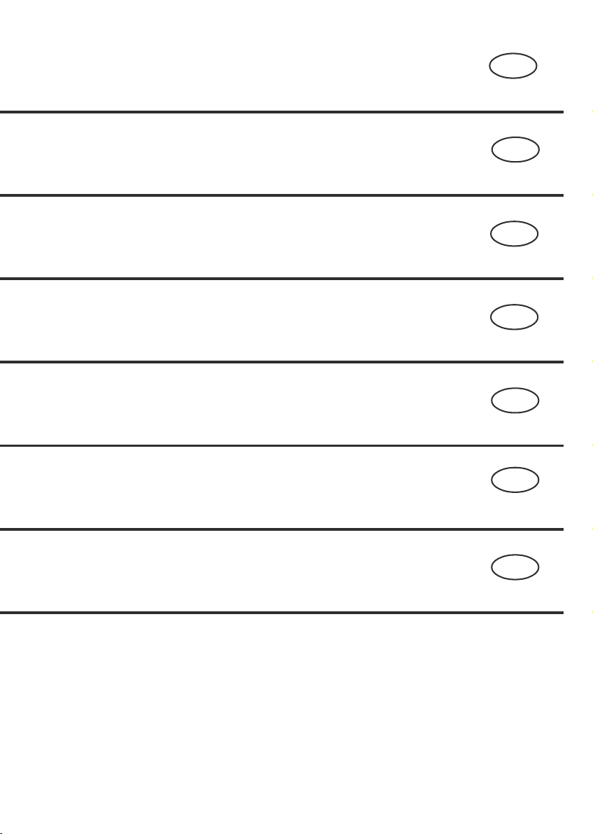
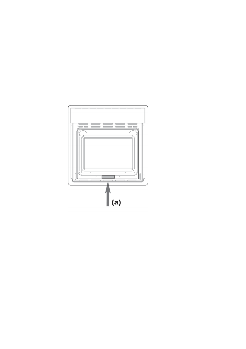
La targhetta (a) delle
caratteristiche del forno è
accessibile anche ad
apparecchio installato. In
questa targhetta, visibile
aprendo la porta, sono
riportati tutti i dati di
identificazione dell’apparecchio, la pressione e il tipo di
gas per il quale è stato
regolato.
Pertanto Vi invitiamo a
seguire attentamente le
istruzioni ed i suggerimenti
per un corretto utilizzo dei
nostri prodotti.
da personale
f e s s i o n a l m e n t e
e in conformità
norme vigenti.
!! IMPORTANT !!
The appliance must be
connected
technician
with
regulations.
(a)
after
installed.
visible
open,
identification
appliance,
gas
which
Follow
suggestions
ensure
use of this product.
by qualified
in accordance
the applicable
The data plate
of the oven is still visible
the appliance has been
This plate, which is
when the oven door is
contains all the
data of the
as well the type of
and service pressure for
it has been calibrated.
the instructions and
carefully to
the safe and proper
!! IMPORTANT !!
L’appareil doit être installé
un personnel qualifié
par
le respect des normes
dans
vigueur. La plaque (a)
en
caractéristiques du four
des
accessible appareil
est
Sur cette plaque,
installé.
en ouvrant la porte,
visible
se trouvent toutes les
de l’appareil, la
données
et le type de gaz
pression
lequel il a été réglé.
pour
vous invitons à suivre
Nous
attentivement
les suggestions pour une
et
utilisation
produits.
les instructions
correcte de nos
2
Page 3

Sehr geehrter Kunde,
ES NL PTDE
Estimado Cliente,
Geachte
klant,
Estimado Cliente,
wir danken Ihnen und
beglckwnschen Sie zu Ihrer
Wahl.
HERSTELLER
DER
Le agradecemos mucho y le
felicitamos por su elecc
FABRICANTE
EL
i n.
wij danken u en feliciteren u
met de door u gedane keuze.
DE FABRIKANT
Agradecemos, muito
sinceramente a sua escolha, e
aproveitamos
a ocasi o para
o felicitar.
O FABRICANTE
!! WICHTIG !!
Das Gerät muss von einem
Fachmann den geltenden
gesetzlichen Auflagen
e n t s p r e c h e n
angeschlossen werden. Das
Identifikationsschild (a) ist
auch nach der Installation
des Gerätes sichtbar. Auf
diesem Schild, das nach
dem Öffnen der Tür sichtbar
wird, stehen alle für die
Identifikation des Gerätes
erforderlichen Daten sowie
der Gastyp und der
Gasdruck, auf den das Gerät
eingestellt ist.
Voraussetzung für eine
korrekte Benutzung unserer
Produkte ist die genaue
Befolgung aller Anleitungen
und Hinweise.
!! IMPORTANTE !!
El aparato tiene que ser
instalado según las normas
vigentes por profesionales
cualificados. La chapa (a)
d
con las características del
horno puede verse abriendo
la puerta y, por lo tanto, no
queda escondida tras
efectuar la instalación. En
esta chapa se facilitan todos
los datos de identificación
del horno así como la
presión y el tipo de gas para
el cual se ha regulado. Para
un uso correcto de nuestros
aparatos, se aconseja leer
atentamente y por completo
las presentes instrucciones.
!! BELANGRIJK !!:
Het apparaat moet door
gekwalificeerd
volgens
voorschriften
aangesloten.
(a) van
toegankelijk
geïnstalleerd
zichtbaar is als de deur
dat
wordt
identificatiegegevens
alle
het apparaat, de druk en
van
gassoort waarvoor het is
de
ingesteld.
ook de aanwijzingen en
dan
adviezen
gebruik
nauwgezet te volgen.
personeel en
de geldende
worden
Het typeplaatje
de oven is ook
als het apparaat
is. Dit plaatje,
geopend, vermeldt
Wij verzoeken u
voor een juist
van onze producten
!! IMPORTANTE !!
O aparelho deve ser
por pessoal
instalado
profissionalmente
e em conformidade com as
em vigor. A chapa
normas
de características do
(a)
está acessível mesmo
forno
o aparelho instalado.
com
chapa, visível abrindo
Nesta
a porta, encontram-se todos
dados de identificação do
os
aparelho,
gás para o qual está
de
regulado.
a seguir atentamente as
lo
instruções
utilização correcta dos
uma
nossos produtos.
qualificado
a pressão e o tipo
Assim, convidamo-
e sugestões para
3
Page 4

IT GB FR
INDICE
ISTRUZIONI PER
L’INSTALLATORE (PAG. 6)
NORME PER L’INSTALLAZIONE
DELL’APPARECCHIO PAG. 6
UBICAZIONE 6
VENTILAZIONE DEL LOCALE 6
ALLACCIAMENTO GAS 8
ALLACCIAMENTO DEL TUBO
METALLICO 8
CONVERSIONE AD ALTRO
TIPO DI GAS 12
TABELLA DEGLI UGELLI 14
REGOLAZIONE DEL MINIMO
NEL CASO DELLA
CONVERSIONE AD ALTRO
TIPO DI GAS 16
INCASSO DEL FORNO 20
ALLACCIAMENTO ELETTRICO
ISTRUZIONI PER
L’UTENTE (PAG. 26)
PRIMO UTILIZZO PAG. 26
PANNELLI AUTOPULENTI 28
DESCRIZIONE FRONTALE
COMANDI
- FORNO A GAS
CON GRILL ELETTRICO 30
- TERMOSTATO DEL FORNO30
- GRILL ELETTRICO 32
-
CONTAMINUTI MECCANICO
DESCRIZIONE FRONTALE
COMANDI
-
FORNO A GAS
CON GRILL GAS
- TERMOSTATO DEL FORNO34
- GRILL GAS 36
-
LUCE FORNO-GIRARROSTO
CONTENTS
INSTRUCTIONS FOR
THE INSTALLER (PAG. 6)
INSTRUCTIONS FOR INSTALLATION
OF THE APPLIANCE
POSITIONING 6
VENTILATION 6
GAS CONNECTION 8
RIGID PIPE CONNECTION 8
CONVERSION TO A
DIFFERENT TYPE OF GAS 12
NOZZLE TABLE 14
ADJUSTMENT OF THE
MINIMUM SETTING
FOLLOWING CONVERSION TO
A DIFFERENT GAS TYPE 16
FLUSH FITTING 20
22
ELECTRICAL CONNECTIONS 22
INSTRUCTIONS FOR
THE USER (PAG. 26)
THE FIRST TIME YOU
USE THE OVEN PAG. 26
SELF-CLEANING CATALYTIC
PANELS 28
DESCRIPTION OF THE FRONT
CONTROL PANEL
- GAS OVEN
WITH ELECTRIC GRILL 30
-
OVEN TEMPERATURE CONTROL
- ELECTRIC GRILL 32
32
-
MECHANICAL MINUTE TIMER
DESCRIPTION OF THE FRONT
CONTROL PANEL
- GAS OVEN
34
WITH GAS GRILL 34
-
OVEN TEMPERATURE CONTROL
- GAS GRILL 36
36
-
OVEN LIGHT- SPIT ROASTER
PAG. 6
INDEX
INSTRUCTIONS POUR
L’INSTALLATEUR (PAG. 6)
NORMES D’INSTALLATION
DE L’APPAREIL PAG. 6
EMPLACEMENT 6
VENTILATION DU LOCAL 6
BRANCHEMENT DU GAZ 8
BRANCHEMENT DU TUBE
MÉTALLIQUE 8
CONVERSION DE TYPE
DE GAZ 12
TABLE DES GICLEURS 14
REGLAGE DU MINIMUM
EN CAS DE CONVERSION
DE GAZ 16
ENCASTREMENT DU FOUR 20
BRANCHEMENT ELECTRIQUE
INSTRUCTIONS POUR
L’UTILISATEUR (PAG. 26)
PREMIERE
UTILISATION PAG. 26
PANNEAUX AUTONETTOYANTS
CATALYTIQUES
DESCRIPTION DU BANDEAU
DE COMMANDE
- FOUR AU GAZ AVEC GRIL
ÉLECTRIQUE 30
30
- THERMOSTAT DU FOUR 30
- GRIL ÉLICTRIQUE 32
32
- MINUTERIE MÉCANIQUE 32
DESCRIPTION DU BANDEAU
DE COMMANDE
- FOUR À GAZ
AVEC GRIL GAZ 34
34
- THERMOSTAT DU FOUR 34
- GRIL GAZ 36
36
-
ECLAIRAGE FOUR - BROCHE
22
28
36
CUOCERE AL FORNO 38
ESTRAZIONE DELLA SUOLA 42
SOSTITUZIONE DELLA
LAMPADA DEL FORNO 44
SMONTAGGIO DELLA
PORTA DEL FORNO 46
RISPETTO DELL’AMBIENTE 48
COOKING IN THE OVEN 38
REMOVAL OF THE BURNER
COVER PLATE 42
REPLACING
THE OVEN LIGHT 44
REMOVING
THE OVEN DOOR 46
RESPECT FOR THE
ENVIRONMENT 48
CUISSON AU FOUR 38
EXTRACTION DE LA SOLE 42
REMPLACEMENT
DE LA LAMPE DU FOUR 44
DEMONTAGE
DE LA PORTE DU FOUR 46
RESPECT DE
L’ENVIRONNEMENT 48
4
Page 5

ES NL PTDE
INDEX
ANLEITUNGEN FÜR DEN
INSTALLATEUR/MONTEUR (S. 7)
FÜR DIE INSTALLATION DES GERÄTES
RELEVANTE NORMEN
STANDORT 7
BELÜFTUNG DES RAUMS 7
GASANSCHLUSS 9
ANSCHLUSS DES
METALLSCHLAUCHES 9
UMSTELLEN AUF EINEN
ANDEREN GASTYP 13
TABELLE DER DÜSEN 15
EINSTELLEN DES MINIMUMS
BEI UMSTELLUNG AUF EINEN
ANDEREN GASTYP 17
EINBAU DES BACKOFENS 21
STROMANSCHLUSS 23
ANLEITUNGEN FÜR DEN
BENUTZER (S. 27)
ERSTMALIGE BENUTZUNG S. 27
SELBSTREINIGENDE
KATALYTISCHE PLATTEN 29
BESCHREIBUNG DER
BEDIENBLENDE
- GASOFEN MIT
ELEKTROGRILL 31
-
BEDIENUNGSEINRICHTUNGEN
- ELEKTROGRILL 33
-
MECHANISCHE MINUTENUHR
BESCHREIBUNG DER
BEDIENBLENDE
- GASOFEN MIT GASGRILL 35
-
BEDIENUNGSEINRICHTUNGEN
- GASGRILL 37
- BELEUCHTUNG OFEN BRATSPIESS 37
IM OFEN BRATEN/BACKEN 39
HERAUSZIEHEN
DES BODENS 43
AUSWECHSLUNG DER OFENBELEUCHTUNG 45
AUSBAUEN DER OFENTÜR 47
UMWELTVERTRÄGLICHKEIT 49
INDICE
INSTRUCCIONES PARA EL
INSTALADOR (PAG. 7)
NORMAS PARA INSTALAR EL
S. 7
APARATO PAG. 7
UBICACIÓN 7
VENTILACIÓN DEL LOCAL 7
CONEXIÓN DEL GAS 9
CONEXIÓN DEL TUBO
METÁLICO 9
CAMBIO DE UN GAS A OTRO 13
TABLA DE LAS BOQUILLAS 15
REGULACIÓN DEL MÍNIMO EN
CASO DE CAMBIO DE GAS 17
ENCASTRE DEL HORNO 21
CONEXIÓN ELÉCTRICA 23
INSTRUCCIONES PARA EL
USUARIO (PAG. 27)
PRIMERA UTILIZACIÓN
PANELES CATALÍTICOS
AUTOLIMPIANTES 29
DESCRIPCIÓN DEL FRONTAL
DE MANDOS
- HORNO DE GAS CON GRILL
ELÉCTRICO 31
31
-
TERMOSTATO DEL HORNO
- GRILL ELÉCTRICO 33
33
- MINUTERO MECÁNICO 33
DESCRIPCIÓN DEL FRONTAL
DE MANDOS
- HORNO DE GAS CON GRILL
DE GAS 35
35
-
TERMOSTATO DEL HORNO
- GRILL DE GAS 37
-
LUZ DEL HORNO Y ASADOR
COCER EN EL HORNO 39
DESMONTAJE
DE LA SOLERA 43
CAMBIO DE LA BOMBILLA DEL
HORNO 45
DESMONTAJE DE LA PUERTA
DEL HORNO 47
RESPETO POR EL MEDIO
AMBIENTE 49
INHOUD
AANWIJZINGEN VOOR DE
INSTALLATEUR (PAG. 7)
INSTALLATIEVOORSCHRIFTEN
VAN HET APPARAAT PAG. 7
PLAATS 7
VENTILATIE VAN HET VERTREK
GASAANSLUITING 9
AANSLUITING VAN DE
METALEN LEIDING 9
OMBOUWEN NAAR EEN
ANDERE GASSOORT 13
TABEL VAN DE INSPUITERS 15
AFSTELLING VAN HET MINIMUM
BIJ HET OMBOUWEN NAAR EEN
ANDERE GASSOORT
INBOUW VAN DE OVEN 21
ELEKTRISCHE AANSLUITING
GEBRUIKSAANWIJZINGEN
PAG
. 27
EERSTE GEBRUIK PAG
KATALYSERENDE
ZELFREINIGENDE PANELEN 29
BESCHRIJVING VAN HET
FRONTBEDIENINGSPANEEL
- GASOVEN MET
ELEKTRISCHE GRILL 31
31
- OVENTHERMOSTAAT 31
- ELEKTRISCHE GRILL 33
- MECHANISCHE KLOK 33
BESCHRIJVING VAN HET
FRONTBEDIENINGSPANEEL
- GASOVEN MET GASGRILL 35
35
- OVENTHERMOSTAAT 35
- GASGRILL 37
37
- OVENVERLICHTING DRAAISPIT 37
BAKKEN MET DE OVEN 39
VERWIJDEREN VAN DE
BODEM 43
HET VERVANGEN VAN HET
LAMPJE VAN DE OVEN 45
DEMONTAGE VAN DE
OVENDEUR 47
RESPECT VOOR HET MILIEU 49
(PAG. 27)
. 27
INDICE
INSTRUÇÕES PARA O
INSTALADOR (PÁG. 7)
NORMAS PARA A INSTALAÇÃO
DO APARELHO PÁG. 7
LOCALIZAÇÃO 7
7
VENTILAÇÃO DO LOCAL 7
LIGAÇÃO DO GÁS 9
LIGAÇÃO
DO TUBO METÁLICO 9
CONVERSÃO PARA OUTRO
TIPO DE GÁS 13
TABELA DOS BICOS 15
REGULAÇÃO DO MÍNIMO EM
CASO DE CONVERSÃO PARA
17
OUTRO TIPO DE GÁS 17
ENCASTRE DO FORNO 21
23
LIGAÇÃO ELÉCTRICA 23
INSTRUÇÕES PARA O
UTILIZADOR (PÁG. 27)
PRIMEIRA UTILIZAÇÃO PÁG
PAINÉIS DE AUTOLIMPEZA
CATALÍTICOS 29
DESCRIÇÃO FRONTAL DOS
COMANDOS
- FORNO A GÁS COM
GRILL ELÉCTRICO 31
- TERMÓSTATO DO FORNO 31
- GRILL ELÉCTRICO 33
-
CONTA-MINUTOS MECÂNICO
DESCRIÇÃO FRONTAL DOS
COMANDOS
- FORNO A GÁS COM
GRILL A GÁS 35
- TERMÓSTATO DO FORNO 35
- GRILL A GÁS 37
- LUZ DO FORNO - ESPETO 37
COZINHAR NO FORNO 39
RETIRAR A COBERTURA 43
SUBSTITUIÇÃO DA LÂMPADA
DO FORNO 45
DESMONTAGEM DA PORTA
FORNO 47
RESPEITO PELO AMBIENTE 49
. 27
33
5
Page 6
IT GB FR
ISTRUZIONI PER
L’INSTALLATORE
NORME PER L’INSTALLAZIONE
DELL’APPARECCHIO
(ubicazione e ventilazione locale)
Le norme italiane che regolano
l’installazione, la manutenzione
e la conduzione degli
apparecchi a gas per uso
domestico sono le seguenti:
- UNI-CIG n. 7129
- UNI-CIG n. 7131
Riportiamo di seguito uno
stralcio di tali norme. Per tutte
le indicazioni non riportate è
necessario consultare le norme
citate.
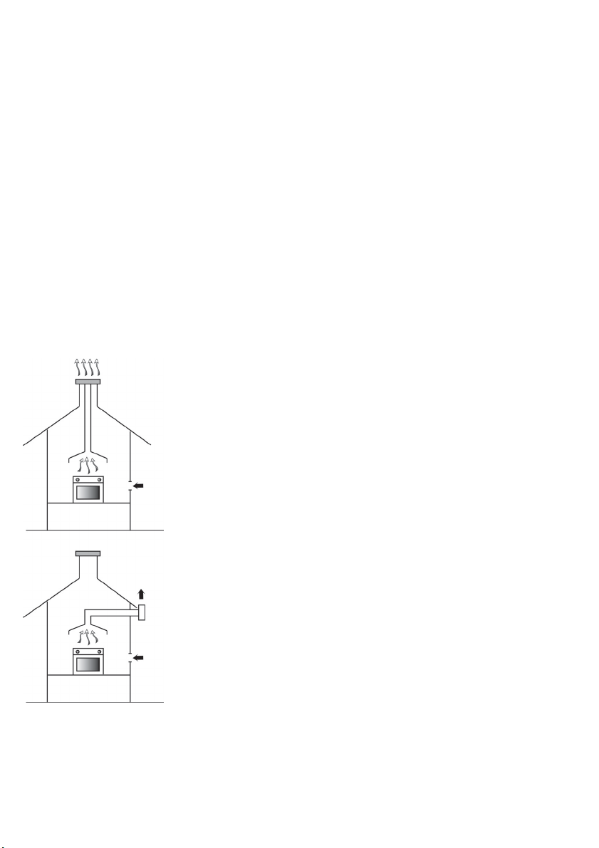
UBICAZIONE:
(Fig. 2) gli apparecchi di cottura
devono sempre scaricare i
prodotti della combustione in
apposite cappe, che devono
essere collegate a camini,
canne fumarie o direttamente
all’esterno.
In caso non esista la possibilità
di applicazione della cappa, è
consentito l’impiego di un
elettroventilatore, installato su
finestra o su parete affacciata
sull’esterno, da mettere in
funzione contemporaneamente
all’apparecchio, purché siano
tassativamente rispettate le
norme inerenti la ventilazione.
INSTRUCTIONS FOR
THE INSTALLER
INSTRUCTIONS FOR
INSTALLATION OF THE
APPLIANCE (positioning and
ventilation requirements)
The regulations covering the
installation, maintenance and
operation of gas appliances for
domestic use are applicable
regulations.
An extract of these regulations
appears below. For all
indications not covered, refer to
the above-mentioned
regulations.
POSITIONING:
(Fig. 2) the products of
combustion from cooking
appliances must always be
discharged into suitable
extractor hoods, which must be
connected to a chimney, flue or
vented directly to outside the
building. In situations where it
is not possible to install an
extractor hood, an electric
extractor fan installed in a
window or external wall may be
used, provided that all
requirements of the ventilation
regulations are satisfied; the
fan should switch on whenever
the appliance is in operation.
INSTRUCTIONS POUR
L’INSTALLATEUR
NORMES D’INSTALLATION
DE L’APPAREIL
(emplacement et ventilation
locale)
Les normes d’installation,
d’entretien et de conduite des
appareils à gaz à usage
domestique sont les normes
en viguer.
Vous trouverez ci-dessous un
aperçu de ces textes. Pour
toutes les indications non
reportées consulter les textes
de référence.
EMPLACEMENT
(Fig. 2) Les appareils de
cuisson doivent toujours
évacuer les produits de
combustion dans des hottes ad
hoc, qui doivent être reliées à
des carneaux de fumées ou
directement à l’extérieur. En
cas d’impossibilité d’installation
de la hotte, utiliser un
électroventilateur installé sur la
fenêtre ou sur un mur orienté
vers l’extérieur, à démarrer
simultanément avec l’appareil,
à condition de respecter
impérativement les normes de
ventilation.
Fig. 2 - Abb. 2 - Afb. 2
6
VENTILAZIONE DEL
LOCALE:
(Fig. 2) è indispensabile che
nel locale in cui sono installati
degli apparecchi a gas possa
almeno affluire tanta aria
comburente quanta ne viene
richiesta dalla combustione del
gas consumato dai vari
apparecchi.
È quindi necessario, per
l’afflusso dell’aria nel locale,
praticare delle aperture che
rispondano ai requisiti
seguenti:
a) avere una sezione libera
totale di 6 cm
con un minimo di 100 cm
(tali aperture possono
eventualmente essere
2
per ogni kW
VENTILATION:
(Fig. 2) it is essential that the
room in which gas appliances
are installed is adequately
ventilated to ensure that all the
appliances receive the required
quantity of fresh air for
combustion.
To ensure an adequate air
flow, it may be necessary to
create apertures in accordance
with the following
requirements:
a) with cross-sectional area of
2
6 cm
per kW with a
minimum cross-sectional
2
area of 100 cm
apertures may also be
created by increasing the
2
VENTILATION DU LOCAL
(Fig. 2) Il est indispensable que
le local d’installation des
appareils à gaz soit aéré en
quantité d’air suffisante pour la
combustion des gaz.
Il est donc indispensable de
pratiquer des ouvertures ad
hoc qui présentent les
caractéristiques suivantes:
a) avoir une section libre totale
de 6 cm
minimum de 100 cm
ouvertures peuvent être
pratiquées en majorant les
ouvertures entre porte et
(these
sol);
b) être situées dans la partie
basse d’une paroi externe,
2
par kW avec un
2
(ces
Page 7

ES NL PTDE
ANLEITUNGEN FÜR DEN
INSTALLATEUR/MONTEUR
FÜR DIE INSTALLATION
DES GERÄTES RELEVANTE
NORMEN (Standort und
Belüftung des Raums)
Für die Installation, die
Wartung und die Benutzung
von Gasgeräten für den
privaten Gebrauch die vor
handenen Normen zu
beachten.
Es folgt ein Auszug aus diesen
Normen. Für alle nicht hier
angeführten Hinweise wird auf
die relevanten Normen
verwiesen.
STANDORT:
(Abb. 2) Kochgeräte müssen ihre
Verbrennungsprodukte immer in
eine zu diesem Zweck
vorgesehene Haube ableiten, die
an einen Kamin oder einen
Rauchkanal angeschlossen sein
muss, oder den Rauch direkt nach
außen abführt. Besteht keine
Möglichkeit, eine
Dunstabzugshaube zu installieren,
kann auch, sofern die
belüftungsrelevanten Normen
eingehalten werden, ein am
Fenster oder einer Außenwand
installierter Elektroventilator benutzt
werden, der gleichzeitig mit dem
Gerät betrieben werden muss.
INSTRUCCIONES
PARA EL INSTALADOR
NORMAS PARA INSTALAR
EL APARATO
(ubicación y ventilación del
local)
Las normas sobre la
instalación, el mantenimiento y
el uso de los aparatos de gas
para uso doméstico son las
normas vigentes.
A continuación, se facilita la
información más importante de
dichas normas. Para cualquier
otra información, hay que
consultarlas directamente.
UBICACIÓN
(fig. 2) Los aparatos de cocción
han de descargar los
productos de la combustión en
campanas que, a su vez, han
de conectarse a chimeneas o
dar directamente al exterior. Si
no es posible instalar una
campana, se permite instalar
un ventilador eléctrico, en una
ventana o pared que dé al
exterior, que funcione siempre
que se ponga en marcha el
aparato. En cualquier caso, se
han de respetar
obligatoriamente las normas
sobre ventilación.
AANWIJZINGEN VOOR
DE INSTALLATEUR
INSTALLATIEVOORSCHRIFTEN
VAN HET APPARAAT
(plaats en ventilatie van het
vertrek)
De normen voor installatie,
onderhoud en bediening van
gasapparaten voor
huishoudelijk gebruik zijn de
volgens de geld mende voor
schriften.
Hieronder volgen een aantal van
deze voorschriften. Voor alle niet
vermelde aanwijzingen moeten
de geciteerde voorschriften
worden geraadpleegd.
PLAATS:
(Afb. 2) de verbrandingsproducten
van kook- en bakapparaten
moeten altijd worden afgevoerd
via een afzuigkap die is
aangesloten op een schoorsteen
of rookkanaal of die rechtstreeks
naar buiten voert. Als het niet
mogelijk is om een afzuigkap toe
te passen, mag een elektrische
ventilator worden gebruikt die op
een raam of op een aan de
buitenmuur grenzende wand is
gemonteerd en die tegelijkertijd
met het apparaat in werking moet
worden gesteld, mits de
ventilatievoorschriften uitdrukkelijk
in acht worden genomen.
INSTRUÇÕES PARA
O INSTALADOR
NORMAS PARA A
INSTALAÇÃO DO APARELHO
(localização e ventilação
local)
As normas que regulam a
instalação, a manutenção e o
funcionamento dos aparelhos a
gás para uso doméstico são as
normas en vigor.
Apresentamos, de seguida, um
extracto dessas normas. Para
todas as indicações não
apresentadas, é necessário
consultar as normas citadas.
LOCALIZAÇÃO:
(Fig. 2) os aparelhos de cozedura
devem sempre descarregar os
produtos da combustão através
de exaustores adequados, que
devem ser ligados a chaminés,
tubagens para evacuação de
fumos ou directamente ao
exterior. Caso não haja
possibilidade de aplicação do
exaustor, é permitida a utilização
de um electroventilador, instalado
na janela ou na parede virada
para o exterior, que deve ser
ligado ao mesmo tempo que o
aparelho, para que sejam
respeitadas as normas inerentes
à ventilação.
BELÜFTUNG DES RAUMS:
(Abb. 2) der Raum, in dem mit
Gas funktionierende Geräte
installiert sind, muss
mindestens mit so viel
Frischluft versorgt werden, wie
zur Verbrennung des von allen
Geräten verbrauchten Gases
erforderlich ist.
Es müssen also für die
Belüftung des Raums
Zuluftöffnungen angebracht
werden, die die folgenden
Voraussetzungen erfüllen:
a) freier Gesamtquerschnitt von
6 cm2 pro kW mit mindestens
100 cm2 (diese Öffnungen
können gegebenenfalls auch
durch Erweiterung des
VENTILACIÓN DEL LOCAL
(fig. 2) Es indispensable que
en el local con los aparatos de
gas llegue todo el aire
comburente requerido por la
combustión de gas de los
diferentes aparatos.
Para ello, hay que realizar
aberturas conformes con los
siguientes requisitos:
a) sección libre total de 6 cm
para cada kW con un
mínimo de 100 cm
necesario, estas aberturas
pueden realizarse
aumentando la rendija entre
las puertas y el suelo);
b) estar en la parte baja de
una pared exterior,
2
(si es
VENTILATIE VAN HET VERTREK:
(Afb. 2) in het vertrek waarin
gasapparaten zijn opgesteld
moet voldoende aanvoer van
verbrandingslucht zijn voor de
verbranding van het gas dat
door de verschillende apparaten
wordt verbruikt.
Voor de aanvoer van lucht in
het vertrek moeten er dus
2
openingen worden gemaakt die
aan de volgende eisen voldoen:
a) de openingen moeten een
totale doorlaat hebben van 6
cm2 voor elke kW met een
minimum van 100 cm2 (deze
openingen kunnen eventueel
worden verkregen door de
spleet tussen de deur en de
VENTILAÇÃO DO LOCAL:
(Fig. 2) é indispensável que no
local onde estejam instalados
aparelhos a gás possa afluir
tanto ar comburente quanto o
exigido pela combustão do gás
consumido pelos vários
aparelhos.
É, assim, necessário, para o
afluxo de ar no local, efectuar
aberturas que correspondam
aos seguintes requisitos:
a) ter uma secção livre total de
6 cm2 por cada kW com um
mínimo de 100 cm2 (tais
aberturas podem ser
efectuadas aumentado o
espaço entre a porta e o
solo);
7
Page 8

IT GB FR
ricavate maggiorando la
fessura tra porta e
pavimento);
b) essere situate nella parte
bassa di una parete
esterna, preferibilmente
opposta a quella in cui si
trova l’evacuazione dei gas
combusti;
c) la loro posizione deve
essere scelta in modo tale
da evitare che possano
essere ostruite e, se
praticate sui muri esterni,
esse devono essere
protette con griglie, reti
metalliche ecc. poste sulla
faccia esterna del muro con
una sezione netta.
In caso nel locale sia installato
un elettroventilatore per
l’evacuazione dell’aria viziata,
le aperture per il ricambio d’aria
devono garantire un passaggio
d’aria di almeno 35 m3/h per
ogni kW di potenza installata in
ambiente.
gap between the bottom of
doors and the floor);
b) situated at the bottom of an
external wall, preferably
opposite the wall on which
combustion products are
extracted ;
c) the positions of the
apertures should selected
so as to avoid the possibility
of their being obstructed
and, if made in external
walls, they must be
protected with grilles, metal
meshes, etc. installed on
the outside face of the wall.
If an electric extractor fan for
the removal of foul air is
installed in the room, the
apertures provided for air
changes must allow a
ventilation rate of at least 35
m3/h per kW of power installed.
de préférence opposée à
celle dans laquelle se trouve
l’évacuation des gaz brûlés;
c) leur position doit être choisie
de façon à éviter qu’elles
soient obstruées et, si
pratiquées sur des murs
externes, elles doivent être
protégées avec des grilles,
des réseaux métalliques
etc. placés sur la façade
externe du mur avec une
section nette.
Si le local est équipé d’un
électroventilateur d’évacuation
de l’air vicié, les ouvertures de
changement d’air doivent
garantir un passage d’air d’au
moins 35 m
puissance installée dans le
local.
3
/h par kW de
ALLACCIAMENTO GAS
Il forno può funzionare a gas
naturale (metano) a gas liquido
(GPL), e può essere facilmente
eseguita la conversione da un
tipo all’altro di gas, come
descritto nei successivi capitoli.
L’allacciamento alla rete di
distribuzione deve essere
eseguito da personale
specializzato e secondo le
prescrizioni relative alle norme
UNI-CIG 7129, 7131.
Nel caso l’apparecchio venga
alimentato con gas liquido
(GPL) in bombola, deve essere
utilizzato un regolatore di
pressione conforme alla norma
UNI CIG 7432.
ALLACCIAMENTO DEL
TUBO METALLICO
L’allacciamento gas può
essere eseguito mediante un
tubo metallico rigido conforme
alla norma UNI 8863 fissato
saldamente al raccordo “G”
(Fig. 3), oppure, mediante un
tubo flessibile di acciaio
inossidabile a parete continua,
di cui alla norma UNI CIG 9891
con lunghezza max. 2 mt.
Il raccordo “G” e la guarnizione
GAS CONNECTION
The oven is designed to
operate with both natural gas
(methane) and liquid gas
(LPG), and can be easily
converted from one type to
another following the
instructions given in the relative
section of this booklet.
Connection to the gas supply
must be carried out by qualified
technicians and in conformance
with the requirements.
If the appliance is to operate
with gas bottles (LPG), a
pressure regulator conforming
to the requirements.
RIGID PIPE
CONNECTION
Connection to the mains gas
supply may be made via a rigid
pipe firmly attached to the
fitting “G” (Fig. 3), or via a
flexible stainless steel
continuous-wall hose,
conforming with a maximum
length of 2 metres.
The fitting “G” and seal “C” are
supplied with the appliance,
and comply with standards.
BRANCHEMENT DU GAZ
Le four peut fonctionner au gaz
naturel (méthane) ou liquide
(GPL). La conversion d’un gaz
à l’autre est facile, comme
expliqué dans les pages
suivantes. Le branchement au
réseau de distribution doit être
fait par une personne
compétente dans le respect
des normes.
Si l’appareil est alimenté en
gaz liquide (GPL) en bouteille,
utiliser un régulateur de
pression conforme à la norme.
BRANCHEMENT DU TUBE
MÉTALLIQUE
Le branchement du gaz doit
être effectué par tube
métallique rigide fixé
solidement au raccord “G” (Fig.
3) ou par flexible acier inox à
mur continu, d’une longueur
max. 2 mètres.
Le raccord “G” et le joint
d’étanchéité “C” sont fournis
comme accessoires avec
l’appareil et sont conformes
8
Page 9

Schlitzes zwischen Tür und
Fußboden erhalten werden);
b) sie müssen sich im unteren
Abschnitt einer Außenwand
befinden, die vorzugsweise
gegenüber der Wand, an der
die Verbrennungsprodukte
abgeführt werden, liegt;
c) sie müssen so platziert
werden, dass sie nicht verlegt
werden können, und wenn sie
sich in einer Außenmauer
befinden, müssen sie durch
klar abgegrenzte Gitter,
Metallnetze o. ä. Vorrichtungen
an der Außenseite der Mauer
geschützt sein.
Sollte im Raum ein
Elektroventilator zur Abführung
der schlechten Luft installiert sein,
müssen die Öffnungen für den
Luftaustausch einen Luftdurchsatz
von mindestens 35 m3/h pro kW
im Raum installierter Leistung
ermöglichen.
ES NL PTDE
preferiblemente en el lado
opuesto a la pared en la
cual se encuentra la salida
de gases quemados;
c) han de estar en una
posición en la cual no
puedan quedar obstruidas
y, si se realizan en paredes
exteriores, han de
protegerse con rejillas,
redes metálicas, etc. por el
lado exterior con una
sección neta.
Si en el local hay un ventilador
eléctrico para evacuar el aire
viciado, las aberturas para
recambiar el aire han de
asegurar un paso de aire de al
menos 35 m3/h para cada kW
de potencia instalada.
vloer te vergroten);
b) de openingen moeten zich
onderaan een buitenwand
bevinden, bij voorkeur
tegenover de afvoer van de
verbrande gassen;
c) de positie van de openingen
moet zodanig worden
gekozen dat verstoppingen
worden voorkomen en als ze
zich in de buitenmuren
bevinden, moeten ze worden
beschermd met roosters,
metalen netwerken, enz. op
de buitenkant van de muur
met een schone doorlaat.
Indien in het vertrek een
elektrische ventilator is
geïnstalleerd voor de afvoer van
afgewerkte lucht, moeten de
openingen voor de
luchtverversing een luchtdoorlaat
van minstens 35 m3/h voor elke
kW geïnstalleerd vermogen in de
ruimte garanderen.
b) estarem situadas na parte
baixa de uma parede
externa, de preferência no
lado oposto àquela em que
se encontra a evacuação
dos gases de combustão;
c)
a sua posição deve ser
escolhida de forma a evitar
que possam ficar obstruídas
e, se efectuadas nas paredes
externas, devem ser
protegidas com grelhas, redes
metálicas, etc., colocadas no
lado externo da parede com
uma secção limpa.
Caso esteja instalado no local
um electroventilador para a
evacuação do ar viciado, as
aberturas para a renovação do
ar devem garantir uma
passagem de ar de pelo
menos 35 m3/h por cada kW
de potência instalada no local.
GASANSCHLUSS
Der Ofen kann mit Erdgas
(Methan) oder Flüssiggas
betrieben und ganz einfach
von einem Gastyp auf den
anderen umgestellt werden
(siehe folgende Abschnitte).
Der Anschluss an das Gasnetz
muss von einem Fachmann
gemäß ausgeführt werden.
Wird das Gerät mit Flüssiggas
aus einer Gasflasche gespeist,
muss ein Druckregler gemäß
benutzt werden.
ANSCHLUSS DES
METALLSCHLAUCHES
Der Gasanschluss kann mit
Hilfe eines steifen
Metallschlauches hergestellt
werden, der fest mit den
Anschluss “G” (Abb. 3)
verbunden sein muss, oder mit
einem rostfreiem
Stahlschlauch mit
durchgehender Wand mit einer
maximalen Länge von 2 m.
Der Anschluss “G” und die
CONEXIÓN DEL GAS
El horno puede funcionar con
gas natural (metano) o con gas
líquido (GPL). El cambio de un
gas a otro es fácil de realizar y
se describe en los capítulos
siguientes. La conexión a la
red de distribución tiene que
ser realizada por profesionales
cualificados según las normas.
Si el aparato se alimenta con
gas líquido (GPL) en
bombona, se ha de emplear un
regulador de presión conforme
con la norma.
CONEXIÓN DEL TUBO
METÁLICO
La conexión del gas puede
realizarse mediante un tubo
metálico rígido firmemente
fijado al empalme “G” (fig. 3) o
bien mediante un tubo flexible
de acero inoxidable de pared
continua con una longitud
máxima de 2 metros.
El empalme “G” y la junta de
retén “C” se suministran como
accesorios con el aparato y
GASAANSLUITING
De oven kan op aardgas
(methaan) en op vloeibaar gas
(LPG) werken en kan eenvoudig
van de ene naar de andere
gassoort worden omgebouwd,
zoals in de volgende hoofdstukken
is beschreven. De aansluiting op
het distributienet moet door
gespecialiseerd personeel worden
verricht volgens de bepalingen
van de normen. Indien het
apparaat wordt gevoed met
vloeibaar gas (LPG) uit een
gasfles, moet gebruik worden
gemaakt van een drukregelaar die
aan de norm.
AANSLUITING VAN DE
METALEN LEIDING
De gasaansluiting kan worden
verricht met een starre metalen
leiding die voldoet aan en die
stevig aan het verbindingsstuk
“G” (Afb. 3) is bevestigd, of met
een doorlopende buigzame
leiding van roestvrij staal met
een maximale lengte van 2
meter.
Het verbindingsstuk “G” en de
afdichting “C” worden als
LIGAÇÃO DO GÁS
O forno pode funcionar com gás
natural (metano) ou gás líquido
(GPL), e pode ser facilmente
efectuada uma conversão para
outro tipo de gás, tal como
descrito nos capítulos
seguintes. A ligação à rede de
distribuição deve ser efectuada
por pessoal especializado e de
acordo com as indicações
relativas às normas. Caso o
aparelho seja alimentado por
gás líquido (GPL) de botija,
deve utilizar-se um regulador de
pressão em conformidade com
a norma.
LIGAÇÃO DO TUBO
METÁLICO
A ligação de gás pode ser
efectuada através de um tubo
metálico rígido, fixo por solda à
união “G” (Fig. 3), ou então,
através de um tubo flexível em
aço inoxidável de parede
contínua, com um
comprimento máximo de 2
metros.
A união “G” e a junta de
vedação “C” são fornecidas
9
Page 10

IT GB FR
di tenuta “C” sono forniti come
accessori assieme
all’apparecchio, e sono
conformi rispettivamente alle
norme UNI ISO 7/1 e UNI 9264.
Importante:
Per l’orientamento del raccordo
“G” operare con due chiavi.
Ottenuta la direzione voluta
bloccare energicamente il dado
“A” (Fig. 3).
Important:
Use two wrenches to turn the
fitting “G” to the required
position. When the fitting is in
the desired position, firmly
tighten nut “A” (Fig. 3).
aux normes.
Important
Pour l’orientation du raccord
“G” utiliser 2 clés. Une fois la
direction obtenue, bloquer
énergiquement avec l’écrou “A”
(Fig. 3).
Fig. 3 - Abb. 3 - Afb. 3
10
ATTENZIONE - IMPORTANTE:
Al termine delle operazioni
di collegamento dell’apparecchio alla rete di
distribuzione gas (o alla
bombola di gas liquido)
CONTROLLARE LA TENUTA dell’accoppiamento
con soluzione di acqua
saponata, mai con una
fiamma.
WARNING - IMPORTANT:
after connecting the
appliance to the gas
supply (or to the liquid gas
bottles) CHECK FOR
LEAKS at the union using
a solution of soapy water
(never use a naked flame).
ATTENTION - IMPORTANT:
à la fin des opérations de
branchement de l’appareil
au réseau de distribution
gaz (ou à la bouteille de
GPL) CONTRÔLER
L’ÉTANCHÉITÉ de l’accouplement avec solution
d’eau savonneuse, jamais
avec une flamme.
Page 11

Dichtung “C” werden
zusammen mit dem Gerät als
Zubehör geliefert und
entsprechen den Normen.
Wichtig:
Zum Ausrichten des
Anschlusses “G” zwei
Schlüssel benutzen. Wenn der
Anschluss in die gewünschte
Richtung zeigt, die Mutter “A”
(Abb. 3) fest anziehen.
ES NL PTDE
son conformes con la norma.
Importante:
Para orientar el empalme “G”
hay que emplear dos llaves.
Tras colocar el empalme en la
dirección deseada, bloquear
bien la tuerca “A” (fig. 3).
accessoires bij het apparaat
geleverd en voldoen
respectievelijk aan de normen.
Belangrijk:
werk voor het richten van het
verbindingsstuk “G” met twee
sleutels. Als de gewenste
richting is bereikt, moet de
moer “A” (Afb. 3) krachtig
worden aangedraaid.
como acessórios do aparelho
e estão em conformidade com
as normas.
Importante:
Para a orientação da união
“G”, trabalhe com duas
chaves. Obtida a direcção
pretendida, aperte com força a
porca “A” (Fig. 3).
ACHTUNG - WICHTIG:
Nach dem Anschließen des
Gerätes an das Gasnetz
(oder die Gasflasche) mit
Seifenwasser - auf keinen
Fall jedoch mit einem
Feuerzeug, einem Zündholz
oder einer offenen Flamme
- KONTROLLIEREN, ob der
Anschluss DICHT ist oder
Gas austritt.
ATENCIÓN - IMPORTANTE:
una vez efectuada la
conexión del aparato a la
red de distribución o a la
bombona de gas líquido,
hay que CONTROLAR LA
ESTANQUEIDAD del
acoplamiento con una
solución de agua y jabón.
No utilizar jamás una
llama.
LET OP - BELANGRIJK:
CONTROLEER na de
aansluiting van het
apparaat op het gasnet (of
op de gasfles) de
AFDICHTING van de
koppeling met sopwater,
nooit met een vlam.
ATENÇÃO - IMPORTANTE:
No final das operações de
ligação do aparelho à rede
de distribuição de gás (ou
à botija de gás líquido)
VERIFIQUE A VEDAÇÃO
da ligação com uma
solução de água e sabão,
nunca com uma chama.
11
Page 12

IT GB FR
CONVERSIONE AD ALTRO
DI GAS
TIPO
Prima
della conversione ad
tipo di gas, accertatevi del
altro
per il quale l’apparecchio è
tipo
regolato. (etichetta
stato
(Figura 1) applicata
adesiva
sull’apparecchio)
Rendere privo di tensione
l’apparecchio
il diametro dell’ugello
Per
riferirsi alla tabella degli ugelli
.
;
CONVERSION TO A
DIFFERENT TYPE OF GA
Before
converting the
for operation with a
appliance
gas type, check which
different
of gas it is currently set to
type
with (adhesive label
operate
(Figure 1) on appliance)
Disconnect
power supply to the appliance;
For
.
diameter,
table in this booklet
the electrical
the correct nozzle
refer to the relative
.
CONVERSION DE TYPE DE
S
Z
GA
Avant
la conversion du gaz,
que le gaz actuel est
vérifier
correctement
(Figure 1) appliquée
adhésive
l’appareil).
sur
.
la tension;
Couper
Pour le diamètre du gicleur,
consulter la table des gicleurs
réglé (étiquette
.
Sostituzione dell’ugello del
bruciatore inferiore
1) Estrarre la suola
copribruciatore
ESTRAZIONE
SUOLA pagina 42)
2) Svitare la vite di fissaggio
bruciatore del forno ed
del
estrarre
insieme
e alla candela di
accensione.
3) Togliere l’ugello dall’attacco
una chiave a tubo da 7
con
(Figura 6
4) Avvitare a fondo il nuovo
ugello
centesimi
sull’ugello)
attenzione
preciso
5) Montare il bruciatore
procedendo
inverso
descritto al punto 2
6) Reinserire la suola nella
posizione giusta.
7) Regolazione del minimo (vedi
istruzioni a pagina 16)
Fig. 5 - Abb. 5 - Afb. 5 Fig. 6 - Abb. 6 - Afb. 6
(vedi
DELLA
.
dal supporto
all’elemento termico
(Figura 5)
)
(diametro impresso in
di millimetro
facendo
all’inserimento
del filetto.
in ordine
rispetto a quanto
.
Replacing the lower burner
nozzle
1) Remove the burner cover
plate
(see REMOVAL OF
BURNER COVER
THE
PLATE page 42)
2) Remove the screw securing
oven burner and
the
withdraw
support together with
the
heat sensor and the
the
ignition
5)
3) Remove the nozzle using a
7 mm box wrench (Figure 6
4) Screw the new nozzle in
(diameter in hundredths
fully
millimetre stamped on the
of
nozzle),
the thread.
cross
5) Replace the burner
reversing
step 2 above
6) Replace the cover plate.
7) Adjusting the minimum flame
(see instructions on page 16)
.
the burner from
spark plug. (Figure
taking care not to
the operations in
.
Remplacement du gicleur
du brûleur inférieur
1) Extraire la sole cachebrûleur
sole page 42)
2) Dévisser la vis de fixation du
brûleur
support
thermique
d’allumage
3) Retirer le gicleur de la
fixation
douille de 7 (Figure 6
4) Visser à fond le nouveau
gicleur
)
centièmes
le gicleur) en faisant
sur
attention
du filetage
5) Monter le brûleur en
procédant
inverse du point 2
6) Remettre en place la sole.
7) Réglage du minimum (voir
directives page 16)
(voir EXTRACTION
.
et extraire du
avec l’élément
et la bougie
(Figure 5).
avec une clé à
)
(diamètre en
de millimètres
à l’insertion précise
.
dans l’ordre
.
12
Page 13

UMSTELLEN
ANDEREN
Vor
dem Umstellen auf einen
anderen
feststellen,
eingestellt
(Abbildung
Das
schalten
Für den Düsendurchmesser
siehe Tabelle der Düsen
AUF EINEN
GASTYP
Gastyp den Gastyp
auf den das Gerät
ist (Klebeetikett
1) auf dem Gerät).
Gerät spannungsfrei
.
.
ES NL PTDE
CAMBIO DE UN GAS A
O
OTR
Antes
de cambiar de gas, hay
controlar para qué tipo se
que
regulado el aparato. Para
ha
véase la chapa adhesiva
ello,
(figura 1) del aparato
Cortar la tensión de
Para
el diámetro de la boquilla,
la tabla de las boquillas.
véase
.
l aparato.
OMBOUWEN
ANDERE
Voor de ombouw naar een
andere gassoort moet u
controleren
apparaat is ingesteld. (sticker
het
(Afbeelding
Sluit het apparaat van de
voedingsspanning af
Raadpleeg
inspuiter de tabel van de
de
inspuiters
NAAR EEN
GASSOORT
voor welke gassoort
1) op het apparaat).
;
voor de diameter van
.
CONVERSÃO
TIPO DE GÁ
Antes da conversão para outro
tipo de gás, verifique o tipo para
o qual o aparelho está regulado.
(etiqueta
aplicada
Desligue a tensão do aparelho;
Para conhecer o diâmetro dos
bicos,
cos.
bi
PARA OUTRO
S
adesiva (Figura 1)
no aparelho).
consulte a tabela dos
Austausch der Düse des
unteren Brenners
1) Die Brennerabdeckung
herausziehen
HERAUSZIEHEN
BODENS Seite 42)
2) Die Schraube, mit der der
Ofenbrenner
ausschrauben
zusammen
Heizelement
Zündkerze
(Abbildung 5
3) Die Düse mit einem 7er-
Steckschlüssel
(Abbildung 6
4) Die neue Düse
aufschrauben
Durchmesser
Düse eingestanzt) und
der
dabei
das Gewinde exakt sitzt
5) Den Brenner wieder
montieren
Punkt
umgekehrter
6) Die Abdeckung wieder
korrekt einsetzen
7) Mindesteinstellung (siehe
Anleitungen auf S. 17)
(siehe
DES
.
befestigt ist,
und ihn
mit dem
und der
herausnehmen.
)
abnehmen.
)
(der
in mm ist auf
darauf achten, dass
.
(wie oben ab
2, jedoch in
Reihenfolge).
.
Sustitución del inyector
del quemador inferior
1) Quitar la solera que cubre el
2) Desenroscar el tornillo de
3) Quitar la boquilla del
4) Enroscar hasta el tope la
5) Montar el quemador
6) Montar la solera.
7) Ajuste del mínimo (véanse las
(véase
quemador
DESMONTAJE
SOLERA, página 42)
fijación
horno
conjuntamente
térmico
encendido
(figura
empalme
tubo de 7 (figura 6)
nueva
impreso
milímetro
controlando
introduzca bien
efectuando
punto 2 en orden
del
inverso
instrucciones en la pág. 17)
DE LA
.
del quemador del
y extraer
el elemento
y la bujía de
de su soporte
5).
con una llave de
.
boquilla (diámetro
en centésimas de
en la boquilla)
que la rosca se
.
las operaciones
.
De s puitmon d van de
onderste brander vervangen
1) Neem de bodem weg die
brander afdekt (zie
de
VERWIJDEREN VAN DE
pagina 42).
BODEM
2)
Draai de bevestigingsschroef
de ovenbrander los en
van
hem samen met het
neem
verwarmingselement en de
van de steun weg.
ontsteker
(Afbeelding
3) Verwijder de inspuiter van
de
van
(Afbeelding
4) Draai de nieuwe inspuiter
goed
op
honderdsten
millimeter)
op
nauwkeurig te plaatsen
5) Monteer de brander in de
omgekeerde
punt 2 is beschreven
6) Plaats de bodem weer in de
juiste
7) De laagste stand afstellen
(zie instructies op pag. 17)
5)
aansluiting met behulp
een steeksleutel nr. 7.
6)
aan (de diameter staat
de inspuiter gedrukt in
van een
en let er daarbij
de schroefdraad
.
volgorde als bij
.
positie.
Substituição do bico do
queimador inferior
1) Extraia a cobertura do
queimador
EXTRACÇÃO
COBERTURA página 42)
2) Desaperte o parafuso de
fixação
forno
juntamente
térmico
(Figura 5
3) Retire o bico do respectivo
suporte
tubos de 7. (Figura 6
4) Aperte totalmente o novo
bico
centésimas
no
que
correctamente
5) Monte o queimador na
ordem
ponto
6) Volte a colocar a cobertura
na posição adequada
7) Regulação do mínimo (ver
instruções da pág.17)
(consultar
DA
.
do queimador do
e extraia do suporte,
com o elemento
e a vela de ignição.
)
com uma chave de
)
(diâmetro impresso em
de milímetros
bico), certificando-se de
insere a rosca
.
inversa à descrita no
2.
.
13
Page 14
IT GB FR
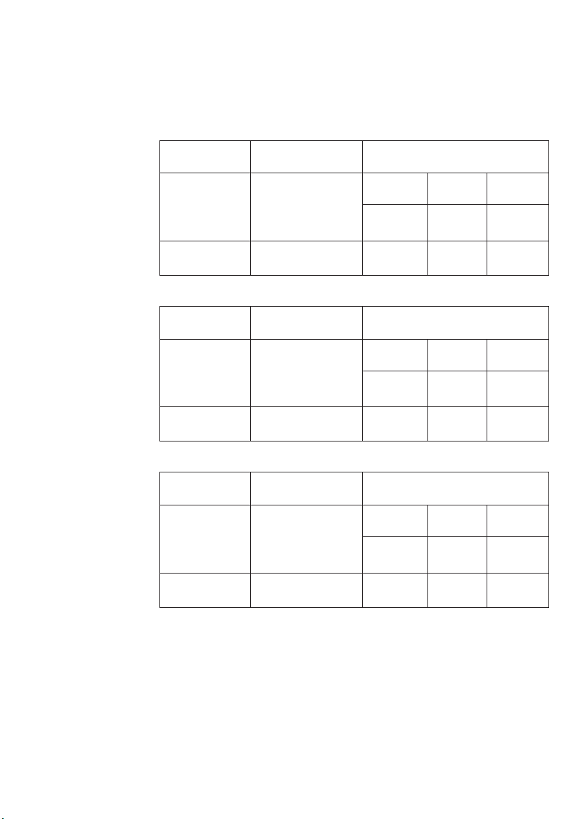
TABELLA DEGLI UGELLI
I diametri sono impressi
sull’ugello in centesimi di
millimetri.
NOZZLE TABLE
The diameters in hundredths of
millimetre are stamped on the
nozzle.
TABLE DES GICLEURS
Les diamètres sont imprimés
sur le gicleur en centièmes de
millimètres.
Bruciatore
Bruciatore forno
Bruciatore grill
Burner
Oven burner
Grill burner
Brûleur
kW
carico nominale
2,50
2,20
kW
rated load
2,50
2,20
kW
Fréquence nominale
Ø Alesaggio ugello
mm
G20 G30 G30
20 mbar 50 mbar 29 mbar
1,13 0,67 0,76
1,12 0,65 0,75
Ø Nozzle bore in
mm
G20 G30 G30
20 mbar 50 mbar 29 mbar
1,13 0,67 0,76
1,12 0,65 0,75
Ø Alésage gicleur
mm
G20 G30 G30
20 mbar 50 mbar 29 mbar
14
Brûleur four
Brûleur gril
2,50
2,20
1,13 0,67 0,76
1,12 0,65 0,75
Page 15
TABELLE DER DÜSEN
Die Durchmesser sind auf der
Düse in Hundertstelmillimeter
angegeben.
ES NL PTDE
TABLA DE LAS BOQUILLAS
Los diámetros están impresos
en la boquilla en centésimas
de milímetro.
TABEL VAN DE INSPUITERS
De diameters zijn op de
inspuiter gedrukt in
honderdsten van een
millimeter.
TABELA DOS BICOS
Os diâmetros estão impressos
no bico em centésimas de
milímetros.
Brenner
Brenner des Ofens
Brenner des Grills
Quemador
Quemador del horno
Quemador del grill
Brander
kW
Nennlast
2,50
2,20
kW
carga nominal
2,50
2,20
kW
nominaal vermogen
Ø Bohrung der Düse in
mm
G20 G30 G30
20 mbar 50 mbar 29 mbar
1,13 0,67 0,76
1,12 0,65 0,75
Ø Diámetro de la boquilla
mm
G20 G30 G30
20 mbar 50 mbar 29 mbar
1,13 0,67 0,76
1,12 0,65 0,75
Ø Boring inspuiter
mm
G20 G30 G30
20 mbar 50 mbar 29 mbar
Ovenbrander
Grillbrander
Queimador
Queimador do forno
Queimador do grill
2,50
2,20
kW
carga nominal
2,50
2,20
1,13 0,67 0,76
1,12 0,65 0,75
Ø Diâmetro do bico
mm
G20 G30 G30
20 mbar 50 mbar 29 mbar
1,13 0,67 0,76
1,12 0,65 0,75
15
Page 16
IT GB FR
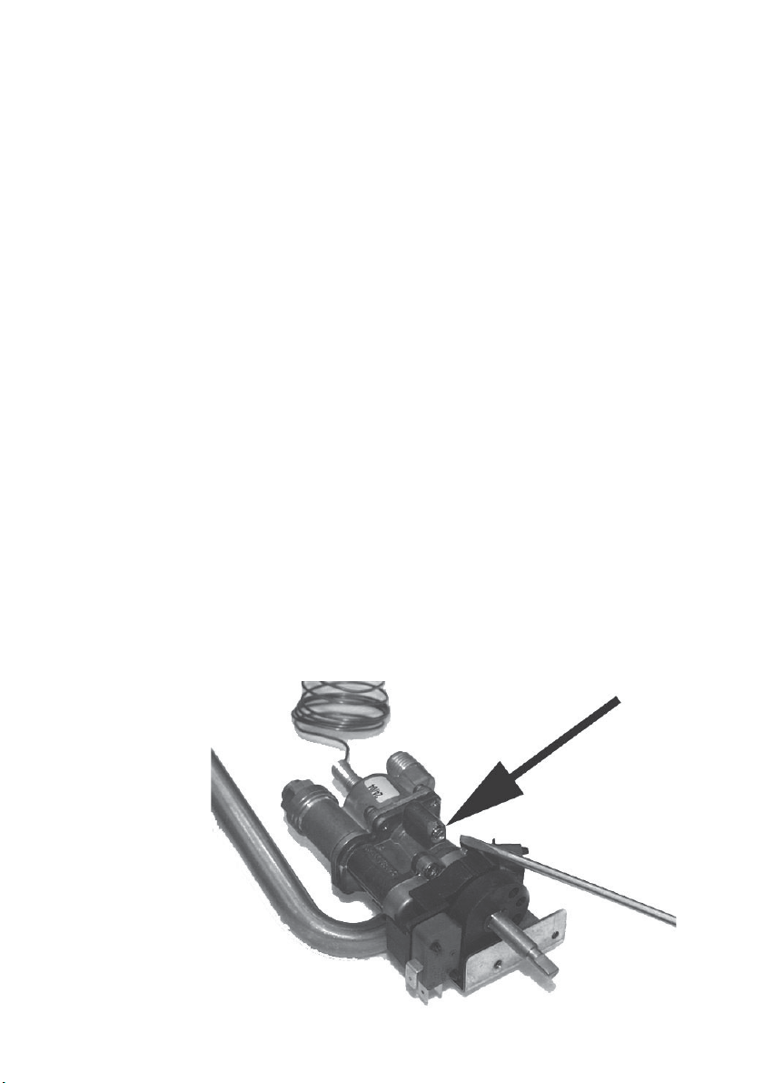
REGOLAZIONE DEL MINIMO
NEL CASO DELLA
CONVERSIONE AD ALTRO
TIPO DI GAS:
1) Da gas naturale a gas
liquido:
Forni con frontale inox
Posizionare la manopola del
termostato gas nella
posizione di minimo, quindi
levarla. Con il cacciavite
entrare attraverso la camma
fino a raggiungere la vite "A"
del bypass. Ruotare a
destra chiudendo a fondo la
vite (vedi fig. 4).
ADJUSTMENT OF THE
MINIMUM SETTING
FOLLOWING CONVERSION
TO A DIFFERENT GAS TYPE:
1) Conversion from natural
gas to LPG:
Ovens with stainless steel
front
Turn the temperature
control knob to the minimum
position, then remove the
knob. Insert a screwdriver
through the aperture to
engage the bypass screw
“A” . Turn the screw fully to
the right (see fig. 4).
RÉGLAGE DU MINIMUM EN
CAS DE CONVERSION DE
GAZ:
1) De gaz naturel à gaz
liquide:
Fours à frontal inox
Placer la manette du
thermostat gaz sur
minimum, et la lever. Avec
un tournevis pénétrer au
travers de la came jusqu’à
atteindre la vis «A» du
bypass. Tourner vers la
droite en fermant à fond la
vis (voir fig. 4).
Forni con frontale vetro
Smontare il frontale
svitando le due ghiere che
lo fissano. Con il cacciavite
passare attraverso il foro
della parete anteriore del
forno e chiudere a fondo la
vite A.
2) Conversione da gas
liquido a gas naturale:
Ruotare il termostato del
forno fino alla posizione
Ovens with glass fronts
Remove the front by
unscrewing the two ring
nuts. Insert a screwdriver
through the hole in the front
wall of the oven and turn the
screw A fully clockwise.
2) Conversion from LPG to
natural gas:
Turn the oven temperature
control knob to the “min”
Fours avec frontal verre
Démonter le frontal en
dévissant les 2 bagues qui
le fixent. Avec le tournevis
passer par le trou de la
paroi AV du four et fermer à
fond la vis A.
2) Conversion de gaz liquide
à gaz naturel:
Tourner le thermostat du
four jusqu’à la position “min”
A
Fig. 4 - Abb. 4 - Afb. 4
16
Page 17

EINSTELLEN DES MINIMUMS
BEI UMSTELLUNG AUF
EINEN ANDEREN GASTYP:
1) Von Erdgas auf
Flüssiggas:
Geräte mit Edelstahlfront
Den Drehregler des
Gasthermostats auf
Minimum stellen und dann
abnehmen.
Den Schraubendreher durch
die Nocke bis zur Schraube
„A“ der Umgehung einführen.
Nach rechts drehen und die
Schraube so ganz schließen
(siehe Abb. 4).
Geräte mit Glasfront
Die Frontblende abnehmen;
dazu die beiden Nutmuttern
lösen.
Den Schraubendreher in
das Loch in der vorderen
Wand des Ofens einführen
und die Schraube A ganz
schließen.
2) Umstellen von Flüssiggas
auf Erdgas:
Den Thermostat des Ofens
in die Stellung “min” drehen
ES NL PTDE
REGULACIÓN DEL MÍNIMO
EN CASO DE CAMBIO DE
GAS:
1) De gas natural a gas
líquido:
Hornos con frontal de
acero inoxidable
Poner el mando del
termostato del gas en la
posición de mínimo y,
luego, quitarlo. Introducir un
destornillador por la leva
hasta alcanzar el tornillo “A”
del by-pass. Girar el
destornillador hacia la
derecha para apretar el
tornillo hasta el tope (fig. 4).
Hornos con frontal de
vidrio
Desenroscar las dos virolas
que sujetan el frontal de
vidrio y quitarlo. Introducir el
destornillador por el orificio
de la pared delantera del
horno y apretar el tornillo “A”
hasta el tope.
2) De gas líquido a gas
natural:
Girar el termostato del
horno hasta la posición de
AFSTELLING VAN HET MINIMUM
BIJ HET OMBOUWEN NAAR EEN
ANDERE GASSOORT:
1) Van aardgas naar
vloeibaar gas:
Ovens met roestvrijstalen
voorkant
Zet de thermostaatknop op
de minimale stand en neem
hem weg. Steek met een
schroevendraaier door de
nok totdat u de schroef “A”
van de bypass bereikt.
Draai naar rechts en sluit de
schroef volledig (zie afb. 4).
Ovens met glazen
voorkant
Demonteer de voorkant door
de twee bevestigingsringen
los te draaien. Steek met de
schroevendraaier door het
gat van de voorwand van de
oven en sluit de schroef A
volledig.
2) Ombouw van vloeibaar
gas naar aardgas:
Draai de thermostaat van
de oven in de stand “min”
REGULAÇÃO DO MÍNIMO
EM CASO DE CONVERSÃO
PARA OUTRO TIPO DE
GÁS:
1) De gás natural para gás
2) Conversão de gás líquido
líquido:
Fornos com frente em
inox
Posicione o manípulo do
termóstato do gás na
posição de mínimo, depois
levante-o. Com a chave de
fenda, entre através da
came até atingir o parafuso
“A” da derivação. Rode para
a direita apertando
totalmente o parafuso
(consulte a fig. 4).
Fornos com frente em
vidro
Desmonte o painel frontal
desapertando as duas
anilhas que o fixam. Com a
chave de fenda, passe
através do furo da parede
dianteira do forno e aperte a
fundo o parafuso A.
para gás natural:
Rode o termóstato do forno
até à posição “mín” e
17
Page 18

IT GB FR
“min” e riscaldare
l’apparecchio
minu
Successivamente
vite
vedere
ma
frontale
Dopo
la conversione ad un
tipo di gas bisogna
altro
correggere
dell’apparecchio
(tipo e pressione del gas).
dati
(Fig. 1
per circa 10
ti.
svitare la
del bypass fino a
una fiamma ridotta
stabile. Rimontare il
.
la targhetta
con i nuovi
)
position and allow the
to warm up for
appliance
about 10 minutes
turn the bypass screw
Then
anticlockwise
but stable flame.
low
Replace
After converting the appliance to
a different type of gas,
to change the data
remember
to one with the new data
plate
type and pressure). (Fig. 1).
(gas
.
to a obtain a
the front.
et chauffer l’appareil
10 minutes.
pendant
la vis de bypass
Dévisser
voir une flamme
jusqu’à
mais stable.
réduite
Remonter le frontal.
Après
la conversion corriger la
de l’appareil avec les
plaquette
données (type et
nouvelles
du gaz). (Fig. 1)
pression
SOSTITUZIONE DELL’UGELLO
PER IL GRILL GAS
1) Svitare la vite di fissaggio del
bruciatore che si trova nella located at the top front of the brûleur qui se trouve sur
parte alta anteriore della oven cavity. l’avant du moufle.
muffola.
2) Estrarre dalla sua sede il
bruciatore assieme ai suoi
elementi termici.
3) Togliere l'ugello con la chiave
a tubo da 7mm.
4) Avvitare a "fondo" il nuovo
ugello che deve essere del
di ametro indic at o nel la
tabella di pag. 14.
5) Reinserire il bruciatore nella
sua sede e fissarlo con la
vite.
REPLACING THE GAS GRILL
NOZZLE
1) Remove the burner screw
2) Remove the burner together
with its heat elements. siège avec l’ensemble des
3) Remove the nozzle using the
7 mm socket wrench.
4) Fully tighten the new nozzle
which must be of the diameter
indica ted in the table on
page 14.
5) Put back the burner and secure
it with the screw.
REMPLACEMENT DU GICLEUR
POUR LE GRILL A GAZ
1) Dévisser la vis de fixation du
2) Extraire le brûleur de son
éléments thermiques.
3) Démonter le gicleur à l’aide
d’une clé à tube 7 mm.
4) Visser à fond le nouveau
gicleur, qui doit impérativement
être de la taille indiquée au
tableau de la page 14.
5) Réinstaller le brûleur dans
son siège et le fixer avec la
vis.
18
Page 19

ES NL PTDE
und das Gerät etwa 10
Minuten lang aufheizen
die Schraube der
Dann
Umgehung
kleine,
zu
Frontblende
montieren
Nach
anderen
Daten
korrigiert
Gastyp und Gasdruck).
für
(Abb
AUSTAUSCH DER DÜSE FÜR
DEN GASGRILL
1) Die Befestigungsschraube
des Brenners, die sich im del quemador que se encuentra van de brander los, die zich in
vorderen Teil oben der Muffe en la parte superior delantera
befindet, abschrauben.
2) Den Brenner zusammen mit
seinen Heizelementen aus quemado r junto con su s
seiner Aufnahme entfernen. van zijn plaats.
3) Mit einem 7mm-Steckschlüssel
die Düsen entfernen.
4) Die neue Düse mit einem in
der Ta b e lle au f S . 15
angegebenen Durchmesser
"tief" einschrauben.
5) Den Brenner wieder in seine
Aufnahme einsetzen und mt
der Befestigungsschraube
befestigen.
lockern, bis eine
aber stabile Flamme
sehen ist. Die
wieder
.
der Umstellung auf einen
Gastyp müssen die
auf dem Geräteetikett
werden (neue Werte
. 1)
mínimo y calentar el aparato
.
durante 10 minutos
desenroscar el
Luego,
del by-pass hasta
tornillo
una llama mínima
lograr
estable. Montar el
pero
frontal.
Tras cambiar de gas, hay que
corregir
la chapa del aparato
con
los nuevos datos de
manera
que conste el tipo y la
presión
del gas correctos. (fig. 1)
SUSTITUCIÓN DEL INYECTOR
PARA EL GRILL GAS
1) Destornillar el tornillo de fijación
de la caja estanca.
2) Sacar de su alojamiento el
elementos térmicos.
3) Quitar el inyector con la llave
de tubo de 7mm.
4) Enroscar hasta el "fondo" el
nuevo inyector que debe tener
el indi cado en la tabl a
de la pág. 15.
5) Volver a introducir el quemador
en su alojamiento y fijarlo
con el tornillo.
.
en
verwarm het apparaat
gedurende
minu
Draai
bypass
u een kleine, maar stabiele
vlam
voorkant weer
Na
de ombouw naar een
andere
nieuwe
typeplaatje
worden
gasdruk). (Afb. 1
DE S PU ITMOND VAN DE
GASGRILL VERVANGEN
1) Draai de bevestigingsschroef
het bovenste gedeelte van de
oven aan de voorkant bevindt.
2) Neem de brander samen met
de verwarmingselementen
3) Verwijder de spuitmond met
een steeksleutel van 7mm.
4) Draai de nieuwe spuitmond,
die de doorsnede moet hebben
die in de tabel van pag. 15
wordt aangeduid, volledig aan.
5) Breng de brander weer op
zijn plaats aan en bevestig
hem met de schroef.
ongeveer 10
ten.
de schroef van de
vervolgens los totdat
ziet. Monteer de
.
gassoort moeten de
gegevens op het
van het apparaat
ingevuld (gassoort en
)
o aparelho durante
aqueça
de 10 minutos.
cerca
seguida, aperte o
De
da derivação até
parafuso
uma chama reduzida
obter
estável. Volte a montar
mas
o painel frontal
a conversão para um
Após
tipo de gás, é necessário
outro
a chapa do aparelho
corrigir
os novos dados (tipo e
com
pressão do gás). (Fig. 1
SUBSTITUIÇÃO DO BICO
PARA O GRILL À GÁS
1) Desaparafusar o parafuso de
fixação do queimador que se
encontra na parte anterior alta
da mufla.
2) Extrair o queimador do seu
alojamento junto com os
seus elementos térmicos.
3) Retirar o bico com a chave
de tubo de 7 mm.
4) Aparafusar a “fundo” o bico
novo que deve ter o diâmetro
indicado na tabela da pág. 15
5) Introduzir de novo queimador
no seu alojamento e fixá-lo
com o parafuso.
.
)
19
Page 20

IT GB FR
INCASSO DEL FORNO
Il forno può essere installato
sotto un piano di cottura
oppure in colonna. Le dimensioni dell’incasso devono essere come riportato in
figura 7.
Il materiale del mobile deve
essere in grado di resistere
al calore. Il forno deve essere centrato rispetto alle pareti
del mobile e fissato con le
viti e bussole che sono
fornite in dotazione.
FLUSH FITTING
The oven can be installed
under a work top or in a
cooking column. The
dimensions of the housing for
the oven are given in figure 7.
Make sure that surrounding
materials are heat resistant.
Align the oven centrally with
respect to the side walls of
the units surrounding it and
fix it in place with the screws
and Allen screws provided.
ENCASTREMENT DU FOUR
Le four peut être installé
sous un plan de cuisson ou
dans une colonne. Les dimensions de l’encastrement
doivent être indiquées figure 7.
Le matériau avec lequel le
meuble est réalisé doit être
en mesure de résister à la
chaleur. Le four doit être
centré par rapport aux parois
du meuble et fixé avec les
vis et les douilles fournies à
cet effet.
Per l’abbinamento del
forno con i piani di cottura
polivalenti gas (figura 8)
vedere le istruzioni
allegate al piano cottura.
Fig. 7 - Abb. 7 - Afb. 7
If a gas hob is to installed in
combination with the oven
refer to the instructions
supplied with the hob (figure
8).
Pour l’accouplement du four
avec des plans de cuisson
polyvalents de gaz (figure 8)
voir les instructions en
annexe du plan de cuisson.
20
Page 21

EINBAU DES BACKOFENS
Der Ofen kann unter einem
Kochfeld oder in einen
Schrank eingebaut werden.
Die Einbaumaße müssen den
Angaben auf der Abbildung 7
entsprechen.
Das Möbelmaterial muss
hitzebeständig sein. Der
Backofen muss zu den
Möbelwänden zentriert, und
mit den mitgelieferten
Schrauben und Buchsen
befestigt werden.
ES NL PTDE
ENCASTRE DEL HORNO
El horno puede ser instalado
debajo de la encimera o en
una columna. Las medidas
del hueco han de serlas
ilustradas en la figura 7.
El material del mueble debe
ser capaz de resistir al calor.
El horno debe ser centrado
respecto de las paredes del
mueble y fijado con los tornillos y casquillos suministrados junto con el producto.
INBOUW VAN DE OVEN
De oven kan worden geïnstalleerd onder een kookplaat of in een hoge kast. De
afmetingen van de inbouw
moeten zodanig zijn als in
afbeelding 7 is weergegeven.
Het materiaal van het
meubel moet hittebestendig
zijn. De oven moet tussen de
wanden van het meubel
worden gecentreerd, en
worden vastgezet met de
inbusschroeven die bij de
oven geleverd zijn.
ENCASTRE DO FORNO
O forno pode ser instalado
debaixo de um plano de
cozedura ou então na
coluna. As dimensões do
encaixe devem ser as
indicadas na figura 7.
O material do móvel deve
ser capaz de resistir ao
calor. O forno deve ser
centrado respeito ás paredes
do móvel e fixado com os
parafusos e buchas que são
fornecidas em dotação.
Für das Kombinieren des
Ofens mit den für mehrere
Gastypen geeigneten
Kochmulden (Abbildung 8)
sind die der Kochmulde
beiliegenden Hinweise und
Anleitungen zu beachten.
Para instalar el horno con
placas de cocción
polivalentes de gas (figura
8), véanse las instrucciones
de la placa de cocción.2
Zie voor de combinatie van
de oven met polyvalente
gaskookplaten (afbeelding
8) de bij de kookplaat
geleverde instructies.
Para a ligação do forno a
placas polivalentes a gás
(figura 8), consulte as
instruções fornecidas com a
placa de fogão.
Fig. 8 - Abb. 8 - Afb. 8
21
Page 22

IT GB FR
ALLACCIAMENTO
ELETTRICO
Prima di effettuare l’allacciamento elettrico accertarsi
che:
-le caratteristiche dell’impianto siano tali da soddisfare quanto indicato sulla
targa matricola applicata
sul fronte del forno;
- l’impianto sia munito di un
efficace collegamento di
terra secondo le norme e
le disposizioni di legge in
vigore. La messa a terra è
obbligatoria a termini di
legge.
Il cavo in nessun punto
dovrà raggiungere una
temperatura superiore di
50° C quella ambiente.
Se un apparecchio fisso
non è provvisto di cavo di
alimentazione e di spina,
o di altro dispositivo che
assicuri la disconnessione
dalla rete, con una
distanza di apertura dei
contatti che consenta la
disconnessione completa
nelle condizioni della
categoria di
sovratensione III, tali
ELECTRICAL
CONNECTIONS
Before connecting the oven
to the mains power supply,
make sure that:
- The supply voltage corresponds to the
specifications on the data
plate on the front of the
oven.
- The mains supply has an
efficient earth (ground)
connection complying with
all applicable laws and regulations. Correct earthing
(grounding) is a legal requirement.
The power cable should
never reach a temperature
50° C above ambient temperature at any point along
its length.
If a fixed appliance is not
provided with a power
cable and plug, or some
other device permitting it
to be disconnected from
the mains electricity
supply, with a gap
between the contacts big
enough to guarantee
class III overvoltage
protection, then such a
BRANCHEMENT
ELECTRIQUE
Avant d’effectuer le branchement électrique, s’assurer que :
-les caractéristiques de l’installation permettent de respecter ce qui est indiqué
sur la plaque d’identification qui est appliquée sur
le devant du four;
- l’installation est munie
d’un raccordement à la prise de terre conforme aux
normes et aux dispositions
prévues par la loi. La mise
à la terre est obligatoire
aux termes de la loi.
Le câble ne doit en aucun
cas atteindre une
température supérieure de
plus de 50° C par rapport
à la température ambiante.
Si un appareil fixe n’a pas
de cordon d’alimentation
et de fiche ou d’autre
dispositif assurant la
déconnexion du secteur,
avec une distance
d’ouverture des contacts
permettant une
déconnexion complète
dans les conditions de la
22
Fig. 9 - Abb. 9 - Afb. 9
Page 23

STROMANSCHLUSS
Vor der Durchführung des
Stromanschluss muss sichergestellt werden, dass:
-die Eigenschaften der
Stromnetzes mit den
Werten auf dem vorne am
Ofen angebrachten Typenschild übereinstimmen;
- das Stromnetz gemäß den
geltenden Bestimmungen
und Rechtsvorschriften geerdet ist.
Die Erdung ist gesetzlich
vorgeschrieben. Das
Kabel darf an keiner Stelle
eine Temperatur von über
50° C erreichen.
Wenn ein Standgerät
nicht mit Netzkabel und stecker oder einer
sonstigen Vorrichtung
ausgestattet ist, das die
Trennung vom Netz
gewährleistet, und dessen
Öffnungsweg der
Kontakte die vollständige
Trennung unter den
Bedingungen der
Überspannungskategorie
III gestattet, so müssen
diese Trenneinrichtungen
ES NL PTDE
CONEXIÓN ELÉCTRICA:
Antes de efectuar la conexión eléctrica cerciorarse de
que:
-las características de la instalación se correspondan
con las indicadas en la
placa situada en la parte
frontal del horno;
-la instalación esté provista
de una eficaz conexión a
tierra según las normas y
las disposiciones de la ley
en vigor. La conexión a
tierra es obligatoria según
la ley.
El cable en ningún punto
deberá alcanzar una
temperatura superior de
50° C a temperatura
ambiente.
Si un aparato fijo no está
provisto de cable de
alimentación con enchufe,
en la red de alimentación
debe incluirse un
dispositivo de corte,
instalado con arreglo a
las disposiciones vigentes
y con una distancia de
apertura de los contactos
que asegure la
ELEKTRISCHE
AANSLUITING
Controleer, voordat u de
elektrische aansluiting tot
stand brengt, of:
- de eigenschappen van de
elektrische installatie overeenstemmen met de gegevens op het typeplaatje
op de voorzijde van de
oven;
- de installatie goed geaard
is volgens de geldende
voorschriften en wettelijke
bepalingen. De aarding is
volgens de wet verplicht.
De kabel mag in geen
geval meer dan 50°
warmer worden dan de
omgevingstemperatuur.
Als een vast apparaat niet
beschikt over een
voedingskabel en stekker
of over een ander
systeem dat de
afkoppeling van het
elektriciteitsnet
garandeert (met een
afstand tussen de
contacten die in
overspanningscategorie
III een complete
afkoppeling mogelijk
LIGAÇÃO ELÉCTRICA
Antes de efectuar a ligação
eléctrica certificar-se que:
- as características da instalação sejam tais que
possam satisfazer quanto
indicado na placa da
matrícula aplicada na
fronte do forno;
-a instalação esteja dotada
de uma eficaz ligação a
terra segundo as normas e
as disposições de lei em
vigor. A ligação a terra é
obrigatória nos termos da
lei.
O cabo em nenhum ponto
deverá atingir uma temperatura superior de 50° C aquela ambiente.
Se um aparelho fixo não
estiver equipado com
cabo de alimentação e
ficha, ou outro dispositivo
que garanta a
desactivação da rede,
com uma distância de
abertura dos contactos
que permita a
desactivação completa
nas condições da
categoria de sobretensão
*TIPI E DIAMETRO DEI CAVI 230V
H05RRF 3 x 1 mm
* CABLE TYPES AND DIAMETERS 230V H05RRF 3 x 1 mm
* TYPES ET DIAMÈTRE DES CÂBLES 230V H05RRF 3 x 1 mm
* KABELTYPEN UND -DURCHMESSER 230V H05RRF 3 x 1 mm
* TIPOS Y DIÁMETRO DE LOS CABLES 230V H05RRF 3 x 1 mm
* KABELTYPES EN DOORSNEDEN 230V H05RRF 3 x 1 mm
* TIPOS E DIÁMETRO DOS CABOS 230V H05RRF 3 x 1 mm
2
2
2
2
2
2
2
23
Page 24

IT GB FR
dispositivi di
disconnessione devono
essere previsti nella rete
di alimentazione
conformemente alle
regole di installazione.
La presa o l’interruttore
onnipolare devono essere
facilmente raggiungibili
con l’apparecchiatura installata.
device must be fitted to
the power supply in
compliance with the
regulations governing
electrical installations.
The socket or switch must
be easily reachable with
the oven fully installed.
catégorie de surtension
III, ces dispositifs de
déconnexion doivent être
prévus dans le réseau
d’alimentation
conformément aux
normes d’installation.
La prise ou l’interrupteur
omnipolaire doit pouvoir
être atteint facilement
lorsque l’appareil est
installé.
N.B. Il costruttore declina
ogni responsabilità nel caso
che quanto sopra e le usuali
norme antinfortunistiche non
vengano rispettate.
N.B. The manufacturer declines all responsibility for
damage or injury if the above
instructions and normal
safety precautions are not
respected.
N.B. Le fabricant décline
toute responsabilité si les
indications présentées dans
ce document et les normes
adoptées habituellement en
matière de prévention des
accidents du travail ne sont
pas respectées.
24
Page 25

gemäß den
Installationsvorschriften
im Versorgungsnetz
vorgesehen sein.
Die Steckdose bzw. der
allpolige Schalter müssen
bei installiertem Gerät
problemlos zugänglich
sein.
ES NL PTDE
desconexión completa en
las condiciones
estipuladas para la
categoría de sobretensión
III.
La toma o el interruptor
omnipolar deben ser de
fácil acceso una vez instalado el aparato.
maakt), dan moeten deze
stroomverbrekers in het
elektriciteitsnet worden
opgenomen in
overeenstemming met de
installatievoorschriften.
Het stopcontact of de
meerpolige schakelaar
moeten gemakkelijk te
bereiken zijn, ook wanneer
de apparatuur
geïnstalleerd is.
III, esses dispositivos de
desactivação devem estar
previstos na rede de
alimentação, em
conformidade com as
instruções de instalação.
A tomada ou o interruptor
omnipolar devem-se poder
atingir facilmente com a
aparelhagem instalada.
N.B. Der Hersteller ist nicht
haftbar, wenn die obigen
Anweisungen und die
üblichen Unfallverhütungsvorschriften nicht befolgt
werden.
Nota: El fabricante declina
toda responsabilidad en el
caso de que todo lo mencionado arriba y las usuales
normas para la prevención
de accidentes no sean respetadas.
N.B. De fabrikant aanvaardt
geen enkele aansprakelijkheid in het geval het bovenstaande en de gebruikelijke regels voor ongevallenpreventie niet in acht
genomen worden.
N.B. O fabricante declina todas as responsabilidades no
caso que quanto acima e as
usuais normas de prevenção
contra os acidentes não
sejam respeitadas.
25
Page 26

IT GB FR
ISTRUZIONI PER
L’UTENTE
PRIMO UTILIZZO
Il forno va pulito a fondo con
acqua e sapone e risciacquato accuratamente. Per
togliere i telai laterali nei forni
con pareti lisce procedere
come illustrato in figura.
Riscaldare il forno per circa
20 minuti alla massima temperatura; verranno così
eliminati tutti i residui grassi
di lavorazione che
potrebbero causare sgradevoli odori in fase di cottura.
INSTRUCTIONS
FOR THE USER
THE FIRST TIME YOU USE
THE OVEN
Clean the oven thoroughly
with soapy water and rinse
well. To remove the lateral
frames from smooth-walled
ovens, proceed as shown in
the figure.
Operate the oven for about
20 minutes at maximum
temperature to burn off all
traces of grease which might
otherwise create unpleasant
smells when cooking.
INSTRUCTIONS
POUR L’UTILISATEUR
PREMIERE UTILISATION
Le four doit être nettoyé à
fond à l’eau et au savon,
puis rincé méticuleusement.
Pour enlever les cadres latéraux dans les fours à parois lisses, procéder comme
indiqué sur la figure.
Il convient de n’insérer la
nourriture que lorsque le four
a atteint la température
préétablie, c’est-à-dire quand
s’éteint le voyant lumineux.
Fig. 10 - Abb. 10 - Afb. 10
26
Importante:
come precauzione di sicurezza prima di procedere a
qualsiasi operazione di pulizia del forno staccare sempre la spina della presa di
corrente o togliere la linea di
alimentazione dell’apparecchio. Inoltre evitare di usare sostanze acide o alcaline (succhi di limone, aceto,
sale, pomodori ecc.). Evitare
di usare prodotti a base di
cloro, acidi o abrasivi specialmente per la pulizia delle
pareti verniciate.
Important:
As a safety precaution,
before cleaning the oven,
always disconnect the plug
from the power socket or the
power cable from the oven.
Do not use acid or alkaline
substances to clean the oven
(lemon juice, vinegar, salt,
tomatoes etc.). Do not use
chlorine based products,
acids or abrasive products to
clean the painted surfaces of
the oven.
Important:
A titre de précaution, avant
d’effectuer toute opération
de nettoyage du four quelle
qu’elle soit, débrancher
toujours la fiche de la prise
de courant ou couper la ligne
d’alimentation de l’appareil.
Veiller à ne pas utiliser de
substances acides ou
alcalines (jus de citron,
vinaigre, sel, tomate, etc.).
Ne pas utiliser de produits à
base de chlore, acides ou
abrasifs, surtout pour le
nettoyage des parois
peintes.
Page 27

ES NL PTDE
ANLEITUNGEN FÜR
DEN BENUTZER
ERSTMALIGE BENUTZUNG
Der Backofen muss
gründlich mit Seifenwasser
gesäubert werden. Wie auf
der Abbildung dargestellt
vorgehen, um bei den Öfen
mit glatten Wänden die
seitlichen Backbleche
herauszunehmen.
Den Backofen für etwa 20
Minuten auf
Höchsttemperatur aufheizen;
auf diese Weise werden alle
fetthaltigen
Bearbeitungsrückstände
eliminiert, die beim Backen
unangenehme Gerüche
verursachen könnten.
INSTRUCCIONES
PARA EL USUARIO
PRIMERA UTILIZACIÓN
El horno se limpia a fondo
con agua y jabón y se
enjuaga cuidadosamente.
Para sacar los armazones
laterales en los hornos con
paredes lisas proceder como
se ilustra en la figura.
Recalentar el horno alrededor de 20 minutos a la
máxima temperatura; serán
así eliminados todos los
residuos grasos ya que podrían causar olores desagradables durante la fase de
cocción.
GEBRUIKSAANWIJZINGEN
INSTRUÇÕES PARA
O UTILIZADOR
EERSTE GEBRUIK
De oven moet grondig worden schoongemaakt met
water en zeep, en zorgvuldig
worden afgespoeld.
verwijderen van de zijframes
in ovens met gladde wanden
dient u te werk te gaan zoals
op de afbeelding wordt
geïllustreerd.
Verwarm de oven gedurende
ongeveer 20 minuten op de
hoogste temperatuur;
zodoende worden alle
achtergebleven vetten
geëlimineerd die onaangename geuren zouden kunnen
veroorzaken tijdens het
bereiden van voedsel.
Voor het
PRIMEIRA UTILIZAÇÃO
O forno deve ser limpo a
fundo com água e sabão e
depois cuidadosamente secado com um pno. Para tirar
as estruturas laterais nos
fornos com paredes lisas
proceder como ilustrado na
figura.
Aquecer o forno à máxima
temperatura por cerca de 20
minutos; assim serão eliminados todos os resíduos de
gorduras de fabrico que poderiam causar cheiros desagradáveis ao cozinhar.
Wichtig:
Als Sicherheitsvorkehrung
muss vor jeder Reinigung
des Backofens immer das
Stromnetz abgeschaltet
werden. Zum Reinigen
dürfen keine sauren oder
alkalischen Substanzen verwendet werden (Zitronensaft,
Essig, Salz, usw.).
Chlorhaltige Produkte, sowie
Säuren oder Scheuermittel
sind ebenfalls zu vermeiden,
dies gilt vor allem für die
Reinigung der lackierten
Wände.
Importante:
Como precaución de seguridad, antes de proceder con
cualquier operación de limpieza del horno quitar
siempre el enchufe de la
toma de corriente o quitar la
línea de alimentación del
aparato. Además evitar el
uso de sustancias ácidas o
alcalinas (jugos de limón,
vinagre, sal, tomates, etc.).
Evitar el uso de productos a
base de cloro, ácidos o abrasivos especialmente para la
limpieza de las paredes
barnizadas.
Belangrijk:
als veiligheidmaatregel moet
altijd de stekker uit het
stopcontact worden gehaald
of moet de voeding van het
apparaat worden
afgekoppeld alvorens de
oven te gaan schoonmaken.
Gebruik bovendien geen
zure of alkaline stoffen (citroensap, azijn, zout, enz.).
Gebruik geen producten op
chloorbasis, of zure of
schurende producten, vooral
voor het reinigen van gelakte
oppervlakken.
Importante:
como precaução de segurança antes de proceder a
qualquer operação de limpeza do forno tirar sempre a
ficha da tomada de corrente
ou tirar a linha de alimentação do aparelho. Além
disso evite usar substâncias
ácidas ou alcalinas (sumos
de limão, vinagre, etc.).
Evitar a utilização de
produtos à base de cloro,
ácidos ou abrasivos especialmente para a limpeza
das paredes envernizadas.
27
Page 28

IT GB FR
PANNELLI AUTOPULENTI
CATALICI
I nostri forni con pareti lisce
hanno la possibilità di montare all’interno della muffola
dei pannelli autopulenti che
ricoprono le pareti.
Questi speciali pannelli, da
agganciare alle pareti prima
dei telai laterali, sono ricoperti di uno speciale smalto
catalitico microporoso che
ossida e vaporizza gradualmente gli schizzi di olio e
grasso eliminandoli durante
le cotture sopra i 200° C.
Se dopo una cottura di cibi
molto grassi il forno non è
pulito, farlo funzionare a
vuoto alla massima temperatura per un tempo massimo
di 60 minuti.
I pannelli autopulenti non devono essere lavati né puliti
con prodotti abrasivi o prodotti contenenti acidi o alcali.
SELF-CLEANING
CATALYTIC PANELS
Our smooth walled ovens
can be fitted with selfcleaning panels to cover the
inside walls.
These special panels are
simply hooked on to the
walls before the side frames
are fitted. They are coated in
a special, micro-porous catalytic enamel which oxidises
and gradually vaporises
splashes of grease and oil at
cooking temperatures above
200° C.
If the oven is not clean after
cooking fatty foods, operate
the empty oven for 60 minutes (max.) at maximum
temperature.
Never wash or clean selfcleaning panels with abrasive, acid, or alkaline
products.
PANNEAUX
AUTONETTOYANTS
CATALYTIQUES
Nos fours à parois lisses
peuvent être munis, à l’intérieur, de panneaux autonettoyants qui recouvrent les
parois.
Devant être accrochés sur
les parois, avant les châssis
latéraux, ces panneaux spéciaux sont recouverts d’un
émail spécial catalytique microporeux qui provoque
l’oxydation et l’évaporation
graduelles des éclaboussures d’huile et de
graisse qui sont ainsi éliminées pendant les cuissons
à plus de 200° C.
Si le four n’est pas propre
après la cuisson d’aliments
très gras, le faire fonctionner
à vide à la température
maximum pendant 60 minutes maximum.
Les panneaux autonettoyants ne doivent être ni
lavés, ni nettoyés avec des
produits abrasifs ou des
produits contenant des
acides ou des alcalis.
28
Fig. 11 - Abb. 11 - Afb. 11
Page 29

SELBSTREINIGENDE
KATALYTISCHE PLATTEN
Unsere Backöfen mit glatten
Wänden bieten die Möglichkeit, in der Muffel
selbstreinigende Platten zu
montieren, mit denen die
Wände verkleidet werden.
Diese Spezialplatten, die vor
den seitlichen Rahmen an
den Wänden eingehängt
werden, sind mit einem
mikroporösen katalytischen
Speziallack bedeckt, der
oxidiert, die Öl- und Fettspritzer nach und nach verdampfen lässt, und so bei
den Backvorgängen über
200°C eliminiert.
Sollte der Ofen nach dem
Backen sehr fetthaltiger
Speisen nicht sauber sein,
lässt man ihn maximal 60
Minuten lang leer bei
Höchsttemperatur eingeschaltet.
Die selbstreinigenden
Platten dürfen weder gewaschen, noch mit
scheuernden oder säurehaltigen bzw. alkalischen
Produkten gereinigt werden.
ES NL PTDE
PANELES CATALÍTICOS
AUTOLIMPIANTES
Nuestros hornos provistos
de paredes lisas, tienen la
posibilidad de llevar montados en su interior paneles
autolimpiantes que recubran
dichas paredes.
Estos paneles especiales,
que se enganchan a las paredes antes de los
bastidores laterales, están
recubiertos de un especial
esmalte catalítico
microporoso que oxida y
vaporiza gradualmente las
salpicaduras de aceite y
grasa eliminándolas durante
las cocciones por encima de
los 200° C.
Si después de una cocción
de alimentos muy grasos el
horno no está limpio,
hacerlo funcionar en vacío a
la máxima temperatura por
un tiempo máximo de 60
minutos.
Los paneles autolimpiantes
no deben ser lavados ni limpiados con productos abrasivos o productos que contengan ácidos o álcali.
KATALYSERENDE
ZELFREINIGENDE
PANELEN
In onze ovens met gladde
wanden kunnen in de moffel
zelfreinigende panelen
worden geplaatst die de
wanden afdekken.
Deze speciale panelen, die
aan de wanden moeten
worden bevestigd voordat
de zijframes worden ge-
plaatst (afb. ...), zijn bedekt
met speciale microporeuze,
katalytische lak die geleidelijk de olie- en vetspatten oxideert en laat
verdampen, zodat ze geëlimineerd worden bij bereidingen boven 200° C.
Als de oven na het bereiden
van erg vet voedsel niet
schoon is, laat hem dan leeg
functioneren op de maximum temperatuur gedurende maximaal 60
minuten”.
De zelfreinigende panelen
mogen niet afgewassen of
schoongemaakt worden met
schurende producten of met
zuur- of alkalihoudende
producten.
PAINÉIS DE
AUTOLIMPEZA
CATALÍTICOS
Os nossos fornos com paredes lisas têm a possibilidade
de montar dentro da mufla
painéis de autolimpeza que
recobrem as paredes.
Estes painéis especiais, que
se engancham às paredes
antes dos bastidores laterais, estão recobertos de um
esmalte especial catalítico
microporoso que oxida e vaporiza gradualmente os salpicos de óleo e gorduras eliminando-as durante o
funcionamento acima dos
200° C.
Se depois de uma cozedura
de alimentos com muito
gordura o forno não estiver
limpo, fazê-lo funcionar a
vazio à máxima temperatura
por um tempo máximo de 60
Os painéis de autilimpeza
não devem ser lavados nem
limpos com produtos abrasivos ou produtos que contenham na sua composição
ácidos ou álcalinos.
29
Page 30

IT GB FR
DESCRIZIONE FRONTALE
COMANDI
FORNO A GAS CON GRILL
ELETTRICO
COMANDI (Fig. 12)
1. Termostato forno a gas
2. Manopola grill, girrarosto e
luce forno
3. Spia forno a gas
4. Contaminuti meccanico
5. Spia grill
Fig. 12 - Abb. 12 - Afb. 12
DESCRIPTION OF THE
FRONT CONTROL PANEL
GAS OVEN WITH ELECTRIC
GRILL
CONTROLS (Fig. 12)
1. Gas oven temperature
control
2. Grill, spit roaster and oven
light knob
3. Gas oven indicator light
4. Mechanical timer
5. Grill indicator light
DESCRIPTION DU BANDEAU
DE COMMANDE
FOUR AU GAZ AVEC GRIL
ÉLECTRIQUE
COMMANDES (Fig. 12)
1. Thermostat four
2. Manette gril, broche et
éclairage
3. Voyant four
4. Minuterie mécanique
5. Voyant gril
Fig. 13 - Abb. 13 - Afb. 13
30
TERMOSTATO DEL FORNO
Il termostato serve ad
impostare la temperatura
desiderata del forno ed è
completo di valvola di
sicurezza. Quando è in
funzione si illumina la spia
verde.
La posizione di minimo
corrisponde ad una
temperatura del forno di 130°C.
Essa dispone di una posizione
d’arresto.
La posizione “max” corrisponde
ad una temperatura del forno di
250°C, e costituisce la
posizione finale del termostato.
Per accendere il bruciatore,
premete la manopola del
termostato e ruotatela in senso
antiorario fino alla temperatura
desiderata.
Tenete premuta la manopola
per circa 5-10 secondi. Durante
questo tempo, il bruciatore
viene acceso elettricamente,
l’elemento termico viene
riscaldato e permette
l’erogazione di gas al
bruciatore.
Non azionate l’accensione per
OVEN TEMPERATURE
CONTROL
The temperature control knob
serves to set the desired oven
temperature and is equipped
with a safety valve. When the
oven is in operation the green
light is illuminated.
The minimum position
corresponds to an oven
temperature of 130°C. The
control knob has stop in the
minimum position.
The “max” position
corresponds to an oven
temperature of 250°C, and is
obtained when the knob is
turned fully anticlockwise.
To light the burner, push in the
temperature control knob and
turn it anticlockwise to the
desired temperature.
Hold the knob pressed in for 510 seconds. The burner will be
ignited electrically, and the
safety valve temperature
sensor will heat up thereby
allowing gas to continue to flow
to the burner.
Do not operate the ignition for
THERMOSTAT DU FOUR
Le thermostat sert à
programmer la température
désirée du four, il est équipé
d’une soupape de sûreté.
Quand il fonctionne le voyant
est vert.
La position de minimum
correspond à une température
du four de 130°C. Elle dispose
d’une position d’arrêt.
La position “max” correspond à
une température du four de
250°C, et constitue la position
finale du thermostat. Pour
allumer le brûleur, appuyer la
manette du thermostat et la
tourner en sens antihoraire
jusqu’à la température voulue.
Appuyer la manette pendant 510 secondes. Pendant ce
temps le brûleur est allumé
électriquement, l’élément
thermique est chauffé et
permet la distribution du gaz au
brûleur.
Ne pas actionner l’allumage
Page 31

BESCHREIBUNG DER
BEDIENBLENDE
GASOFEN MIT
ELEKTROGRILL
BEDIENUNGSEINRICHTUNGEN
(Abb. 12)
1. Thermostat Gasofen
2. Drehregler Grill, Bratspieß
und Innenbeleuchtung
3. Kontrolllampe Gasofen
4. Mechanische Minutenuhr
5. Kontrolllampe Grill
ES NL PTDE
DESCRIPCIÓN DEL FRONTAL
DE MANDOS
HORNO DE GAS CON GRILL
ELÉCTRICO
MANDOS (fig. 12)
1. Termostato del horno de
gas
2. Mando del grill, el asador y
la luz del horno
3. Testigo del horno de gas
4. Minutero mecánico
5. Testigo del grill
BESCHRIJVING VAN HET
FRONTBEDIENINGSPANEEL
GASOVEN MET
ELEKTRISCHE GRILL
BEDIENINGEN (Afb. 12)
1. Thermostaat gasoven
2. Regelknop grill, draaispit en
ovenverlichting
3. Controlelampje gasoven
4. Mechanische klok
5. Controlelampje grill
DESCRIÇÃO FRONTAL DOS
COMANDOS
FORNO A GÁS COM GRILL
ELÉCTRICO
COMANDOS (Fig. 12)
1. Termóstato do forno a gás
2. Manípulo do grill, espeto e
luz do forno
3. Luz piloto do forno a gás
4. Conta-minutos mecânico
5. Luz piloto do grill
THERMOSTAT DES OFENS
Der Thermostat dient zum
Einstellen der gewünschten
Ofentemperatur und ist mit
einem Sicherheitsventil
ausgestattet. Wenn er in
Betrieb ist, leuchtet das grüne
Lämpchen.
Die Position min. entspricht
einer Ofentemperatur von
130°C. Sie hat auch eine
Einraststellung.
Die Position “max” entspricht
einer Ofentemperatur von
250°C und ist auch die obere
Endeinstellung des
Thermostats. Zum Anzünden
des Brenners den Drehregler
des Thermostats drücken und
gegen den Uhrzeigersinn auf
die gewünschte Temperatur
drehen.
Den Drehregler etwa 5 bis 10
Sekunden lang gedrückt
halten. In dieser Zeit wird der
Brenner elektrisch gezündet,
das Heizelement wird
aufgeheizt und macht so die
Versorgung des Brenners mit
Gas möglich.
Die Zündung nicht länger als 15
TERMOSTATO DEL HORNO
Sirve para programar la
temperatura deseada del
horno e incorpora una válvula
de seguridad. Cuando está en
marcha, el testigo verde se
enciende.
La posición de mínimo
corresponde a una
temperatura del horno de
130°C. Tiene una posición de
apagado.
La posición de máximo
corresponde al tope del
termostato y calienta el horno a
250°C. Para encender el
quemador, apretar el mando
del termostato y girarlo en
sentido contrario a las agujas
del reloj hasta la temperatura
deseada.
Mantener apretado el mando
entre 5 y 10 segundos.
Durante este tiempo, el
quemador se enciende
eléctricamente, el elemento
térmico se calienta y el gas
llega al quemador.
No mantener apretado el
OVENTHERMOSTAAT
De thermostaat dient om de
gewenste temperatuur van de
oven in te stellen en is uitgerust
met een veiligheidsklep. Als de
thermostaat werkt, brandt het
groene controlelampje.
De minimale stand stemt
overeen met een
oventemperatuur van 130°C.
Deze beschikt over een
stopstand.
De “max” stand stemt overeen
met een oventemperatuur van
250°C en vormt de eindstand
van de thermostaat. Druk op
de thermostaatknop en draai
hem tegen de klok op de
gewenste temperatuur om de
brander te ontsteken.
Houd de knop ongeveer 5-10
seconden ingedrukt. De
brander wordt nu elektrisch
ontstoken, het
verwarmingselement wordt
verwarmd en maakt de
gastoevoer naar de brander
mogelijk.
Druk de ontsteking niet langer
TERMÓSTATO DO FORNO
O termóstato serve para
programar a temperatura
pretendida do forno e está
equipado com uma válvula de
segurança. Quando está a
funcionar, a luz piloto verde
acende-se.
A posição do mínimo
corresponde a uma
temperatura do forno de
130°C. Esta dispõe de uma
posição de paragem.
A posição “máx” corresponde
a uma temperatura do forno de
250°C e constitui a posição
final do termóstato. Para
acender o queimador, prima o
manípulo do termóstato e
rode-o para a esquerda até à
temperatura pretendida.
Mantenha premido o manípulo
durante cerca de 5-10
segundos. Durante este
tempo, o queimador acende-se
electricamente, a resistência
aquece e permite a distribuição
do gás ao queimador.
Não accione a ignição durante
31
Page 32

IT GB FR
più di 15 secondi. In caso di
mancata accensione del
bruciatore, tornate a premere
la manopola solo dopo aver
lasciato aperta la porta per
almeno 1 minuto.
Se l’accensione elettrica non
dovesse funzionare, avvicinare
un fiammifero acceso in
corrispondenza del foro che
permette di visualizzare il
bruciatore e contemporaneamente premere la
manopola del termostato nella
posizione “max” per 5÷10
secondi.
longer than 15 seconds. If the
burner fails to ignite, leave the
door open for at least one
minute, then try again.
If the electrical ignition fails to
produce a spark, hold a lit taper
or match near the burner
inspection hole and press and
hold the temperature control
knob in the “max” position for 5
to 10 seconds.
pendant plus de 15 secondes.
En cas d’absence de brûleur,
appuyer la manette après avoir
laissé ouverte la porte pendant
1 minute.
Si l’allumage électrique ne
fonctionne pas, approcher une
allumette allumée du regard de
visualisation du brûleur et
appuyer la manette du
thermostat dans la position
“max” pendant 5÷10 secondes.
Fig. 14 - Abb. 14 - Afb. 14
Fig. 15 - Abb. 15 - Afb. 15
GRILL ELETTRICO
Grill infrarosso: il forno è
provvisto di un regolatore di
energia. L’intensità di
irraggiamento della resistenza
grill può essere regolata da 1 a
MAX con l’apposita manopola
(Fig. 14). Quando la funzione
grill è inserita si accende la
spia e contemporaneamente la
luce interna del forno. Per far
funzionare il motorino
girarrosto si deve ruotare la
manopola fino al simbolo
e si avvertirà uno scatto.
Portare quindi la manopola alla
potenza desiderata, da
posizione 0 a 8.
ATTENZIONE: Il grill non
funziona quando è inserita la
funzione gas del forno.
CONTAMINUTI MECCANICO
Il contaminuti è un avvisatore
acustico a tempo, indipendente
dal funzionamento del forno,
che può essere regolato per un
periodo massimo di 60 minuti.
La manopola di regolazione
(Fig. 15) deve essere ruotata in
senso orario fino alla posizione
60 minuti e poi posizionata
ruotandola in senso antiorario
facendo coincidere l’indice con
il tempo desiderato.
Trascorso il tempo stabilito
interviene un segnale acustico
che cessa automaticamente.
ELECTRIC GRILL
Infrared grill: equipped with an
energy regulator. The heat
intensity of the grill can be set
from 1 to MAX using the
relative control knob (Fig. 14).
When the grill is in operation,
the grill indicator light and the
oven interior light will be
illuminated. To operate the spit
roaster motor, turn the knob to
the symbol
click. Then turn the knob to
desired power setting from 0 to
8.
WARNING: The grill will not
operate when the oven is on.
MECHANICAL MINUTE TIMER
The minute timer can be set to
a maximum time of 60
minutes; it emits an alarm tone
when the set time period has
elapsed. The minute timer
operates independently of the
oven.
The timer knob (Fig. 15) must
first be turned clockwise to the
60 minute position and then
turned anti-clockwise to the
desired time setting.
When the set time has elapsed,
the alarm will sound. The alarm
tone will stop automatically
after a certain period.
until you feel a
GRIL ÉLECTRIQUE
Gril infrarouge: le four est
équipé d’un régulateur
d’énergie. L’intensité
d’irradiation de la résistance gril
peut être réglée de 1 à MAX
avec la manette (Fig. 14).
Quand la fonction gril est
insérée le voyant s’allume et
simultanément l’éclairage
interne du four. Pour faire
fonctionner le moteur de la
broche tourner la manette
jusqu’au symbole
entend un déclic. Porter la
manette à la puissance voulue,
de 0 à 8.
ATTENTION: le gril ne
fonctionne pas quand est
insérée la fonction gaz du four.
MINUTERIE MÉCANIQUE
La minuterie est un avertisseur
acoustique temporisé,
indépendant du
fonctionnement du four, qui
peut être réglé pendant 60
minutes maximum.
La manette de réglage (Fig.
15) doit être tournée en sens
horaire jusqu’à la position 60
minutes, et en sens inverse
jusqu’au temps voulu.
A la fin du temps fixé une
sonnerie se déclenche et
cesse automatiquement.
, on
32
Page 33

Sekunden betätigen. Wenn der
Brenner beim ersten Mal nicht
gezündet wurde, den Drehregler
loslassen und aus Sicherheitsgründen
erst dann wieder drücken, wenn die
Ofentür mindestens 1 Minute lang
offen gelassen worden ist, damit das
Gas entweichen kann.
Sollte die elektrische Zündung
nicht funktionieren, kann der Ofen
auch angezündet werden, indem
man ein brennendes Zündholz an
das Loch hält, durch das man den
Brenner beobachten kann und
gleichzeitig den Drehregler des
Thermostats 5 bis 10 Sekunden
lang auf “max” gedrückt hält.
mando por más de 15
segundos. Si el quemador no
se enciende, volver a apretar el
mando sólo tras dejar la puerta
abierta durante 1 minuto como
mínimo.
Si el encendido eléctrico no
funciona, acercar una cerilla
encendida al orificio por el cual
se ve el quemador y, al mismo
tiempo, apretar el mando del
termostato, colocado en la
posición de máximo, entre 5 y
10 segundos.
ES NL PTDE
dan 15 seconden in. Als de
brander niet wordt ontstoken,
druk dan de knop opnieuw in
nadat u de deur minstens 1
minuut open hebt gelaten.
Als de elektrische ontsteking
niet werkt, houd dan een
brandende lucifer bij het gat
waardoor de brander zichtbaar
is en houd tegelijkertijd de
thermostaatknop gedurende
5÷10 seconden ingedrukt op
de “max” stand.
mais de 15 segundos. Em
caso de falha de ignição do
queimador, volte a premir o
manípulo só depois de ter
deixado a porta aberta durante
pelo menos 1 minuto.
Se a ignição eléctrica não
funcionar, aproxime um fósforo
aceso do respectivo orifício,
permitindo visualizar o
queimador e, ao mesmo
tempo, prima o manípulo do
termóstato na posição “máx”
durante 5÷10 segundos.
ELEKTROGRILL
Infrarot-Grill: Der Ofen ist mit
einem Energieregler ausgestattet.
Die Strahlungsintensität des
Grillwiderstandes kann mit dem
Drehregler (Abb. 14) von 1 bis
MAX eingestellt werden. Wenn
die Grillfunktion eingeschaltet ist,
leuchtet das Kontrolllämpchen
und gleichzeitig auch die
Innenbeleuchtung des Ofens.
Zum Einschalten des
Bratspießmotors muss der
Drehregler auf
werden; es ist ein Einschnappen
zu verspüren. Dann den
Drehregler auf die gewünschte
Leistungsstufe von 0 bis 8 stellen.
ACHTUNG: Der Grill funktioniert
nicht, wenn die Gasfunktion des
Ofens eingeschaltet ist.
MECHANISCHE MINUTENUHR
Die Minutenuhr funktioniert
unabhängig vom Gerät, weist
durch ein akkustisches
Warnsignal darauf hin, dass
die eingestellte Zeit abgelaufen
ist und kann maximal auf 60
Minuten eingestellt werden.
Den Drehregler (Abb. 15)
zuerst im Uhrzeigersinn bis auf
60 Minuten drehen und dann
gegen den Uhrzeigersinn die
gewünschte Zeit einstellen.
Nach Ablauf der vorgegebenen
Zeit ertönt ein akkustisches
Signal, das sich nach einiger
Zeit automatisch abstellt.
gestellt
GRILL ELÉCTRICO
Grill infrarrojo: el horno posee
un regulador de energía. La
intensidad de irradiación de la
resistencia del grill puede
regularse de 1 a MÁX. con el
correspondiente mando (fig.
14). Cuando el grill está en
marcha, se enciende la luz
interna del horno. Para poner
en marcha el motor del asador,
girar el mando hasta el
símbolo
Luego, poner el mando a la
potencia deseada (de 0 a 8).
ATENCIÓN: el grill no funciona
si el horno está encendido.
MINUTERO MECÁNICO
El minutero es una avisador
acústico temporizado,
independiente del funcionamiento
del horno, que se puede programar
para un periodo máximo de 60
minutos.
El mando de regulación (fig. 15) se
ha de girar en el sentido de las
agujas del reloj hasta la posición de
60 minutos y, luego, se ha de girar
en sentido contrario a las agujas del
reloj hasta la posición
correspondiente al tiempo deseado.
Transcurrido dicho tiempo, se
produce una señal acústica que
termina automáticamente.
. Se oye un clic.
ELEKTRISCHE GRILL
Infrarood grill: de oven is voorzien
van een energieregelaar.
De stralingssterkte van de
grillweerstand kan met de knop
worden ingesteld van 1 tot MAX
(Afb. 14). Als de grillfunctie is
ingeschakeld, gaat het
controlelampje branden en
tegelijkertijd de binnenverlichting
van de oven. Om het motortje
van het draaispit te laten werken
moet de knop tot het symbool
een klik. Zet de knop vervolgens
op het gewenste vermogen, van
de stand 0 tot 8.
LET OP: de grill werkt niet als
de gasfunctie van de oven is
ingeschakeld.
MECHANISCHE KLOK
De klok is een geluidssignaal
op tijd en werkt onafhankelijk
van de oven. De klok kan
worden ingesteld voor een
maximale duur van 60
minuten.
De regelknop (Afb. 15) moet
met de klok worden
meegedraaid tot de stand 60
minuten en vervolgens tegen
de klok in worden gedraaid om
de wijzer met de gewenste tijd
samen te laten vallen.
Na de vastgestelde tijd klinkt
een geluidssignaal dat
automatisch stopt.
worden gedraaid. U hoort
GRILL ELÉCTRICO
Grill de infra-vermelhos: o forno
possui um regulador de
potência. A intensidade da
irradiação da resistência do
grill pode ser regulada de 1 a
MAX com o respectivo
manípulo (Fig. 14). Quando a
função grill é activada, acendese a luz piloto e, ao mesmo
tempo, a luz interna do forno.
Para ligar o motor de rotação
do espeto, deve rodar o
manípulo até ao símbolo
ouvindo-se um estalido. De
seguida, coloque o manípulo
na potência pretendida, da
posição 0 a 8.
ATENÇÃO: O grill não
funciona quando é accionada
a função de gás do forno.
CONTA-MINUTOS MECÂNICO
O conta-minutos mecânico é um
avisador acústico de tempo,
independente do funcionamento
do forno, que pode ser regulado
por um período máximo de 60
minutos.
Rode o manípulo de regulação
(Fig. 15) para a direita até à
posição 60 minutos e, de
seguida, rode-o para a
esquerda fazendo coincidir o
indicador com o tempo
pretendido.
Decorrido o tempo estabelecido,
é emitido um sinal acústico que
pára automaticamente.
,
33
Page 34

IT GB FR
DESCRIZIONE FRONTALE
COMANDI
FORNO A GAS CON GRILL
GAS
COMANDI (Fig. 16)
1. Termostato suola e grill gas
2. Manopola luce forno e
girarrosto
3. Spia forno a gas
4. Contaminuti meccanico
5. Spia funzionamento elettrico
Fig. 16 - Abb. 16 - Afb. 16
DESCRIPTION OF THE
FRONT CONTROL PANEL
GAS OVEN WITH GAS
GRILL
CONTROLS (Fig. 16)
1. Lower burner and gas grill
temperature control knob
2. Oven and spit roaster
control knob light
3. Gas oven indicator light
4. Mechanical timer
5. Electrical indicator light
DESCRIPTION DU BANDEAU
DE COMMANDE
FOUR À GAZ AVEC GRIL
GAZ
COMMANDES (Fig. 16)
1. Thermostat sole et gril gaz
2. Manette éclairage et broche
3. Voyant four
4. Minuterie mécanique
5. Voyant fonctionnement
électrique
Fig. 17 - Abb. 17 - Afb. 17
34
TERMOSTATO DEL FORNO
Il termostato serve ad
impostare la temperatura
desiderata del forno ed è
completo di valvola di
sicurezza. Quando è in
funzione si illumina la spia
verde.
Per accendere il bruciatore
inferiore premete la manopola
del termostato e ruotatela in
senso antiorario fino alla
temperatura desiderata.
La posizione di minimo
corrisponde ad una
temperatura del forno di
130°C. Essa dispone di una
posizione d’arresto.
La posizione di massimo
corrisponde ad una
temperatura del forno di
250°C, e costituisce la
posizione finale del termostato.
Tenete premuta la manopola
per circa 5-10 secondi.
Durante questo tempo, il
bruciatore viene acceso
elettricamente, l’elemento
termico viene riscaldato e
permette l’erogazione di gas al
bruciatore.
OVEN TEMPERATURE
CONTROL
The temperature control knob
serves to set the desired oven
temperature and is equipped
with a safety valve. When the
oven is in operation the green
light is illuminated.
To turn on the bottom burner,
push in the temperature control
knob and turn it anticlockwise
to the desired temperature.
The minimum position
corresponds to an oven
temperature of 130°C. The
control knob has stop in the
minimum position.
The maximum position
corresponds to an oven
temperature of 250°C, and is
obtained when the knob is
turned fully anticlockwise.
Hold the knob pressed in for 510 seconds. The burner will be
ignited electrically, and the
safety valve temperature
sensor will heat up thereby
allowing gas to continue to flow
to the burner.
THERMOSTAT DU FOUR
Le thermostat sert à
programmer la température
désirée du four, il est équipé
d’une soupape de sûreté.
Quand il fonctionne le voyant
est vert.
Pour allumer le brûleur inférieur
appuyer la manette du
thermostat et la tourner en
sens antihoraire jusqu’à la
température voulue.
La position de minimum
correspond à une température
du four de 130°C. Elle dispose
d’une position d’arrêt.
La position de maximum
correspond à une température
du four de 250°C, et constitue
la position finale du thermostat.
Appuyer la manette pendant 510 secondes. Pendant ce
temps le brûleur est allumé
électriquement, l’élément
thermique est chauffé et
permet la distribution du gaz au
brûleur.
Page 35

BESCHREIBUNG DER
BEDIENBLENDE
GASOFEN MIT GASGRILL
BEDIENUNGSEINRICHTUNGEN
(Abb. 16)
1. Thermostat Boden und
Gasgrill
2. Drehregler
Innenbeleuchtung Ofen und
Bratspieß
3. Kontrolllampe Gasofen
4. Mechanische Minutenuhr
5. Kontrolllampe elektrischer
Betrieb
ES NL PTDE
DESCRIPCIÓN DEL FRONTAL
DE MANDOS
HORNO DE GAS CON GRILL
DE GAS
MANDOS (fig. 16)
1. Termostato de la solera y
grill de gas
2. Mando de la luz del horno y
del asador
3. Testigo del horno de gas
4. Minutero mecánico
5. Testigo de funcionamiento
eléctrico
BESCHRIJVING VAN HET
FRONTBEDIENINGSPANEEL
GASOVEN MET GASGRILL
BEDIENINGEN (Afb. 16)
1. Thermostaat bodem en
gasgrill
2. Knop ovenverlichting en
draaispit
3. Controlelampje gasoven
4. Mechanische klok
5. Controlelampje elektrische
werking
DESCRIÇÃO FRONTAL DOS
COMANDOS
FORNO A GÁS COM GRILL
A GÁS
COMANDOS (Fig. 16)
1. Termóstato e grill a gás
2. Manípulo da luz do forno e
espeto
3. Luz piloto do forno a gás
4. Conta-minutos mecânico
5. Luz piloto de funcionamento
eléctrico
THERMOSTAT DES OFENS
Der Thermostat dient zum
Einstellen der gewünschten
Ofentemperatur und ist mit
einem Sicherheitsventil
ausgestattet. Wenn er in
Betrieb ist, leuchtet das grüne
Lämpchen.
Zum Einschalten des unteren
Brenners den Drehregler des
Thermostats drücken und
gegen den Uhrzeigersinn auf die
gewünschte Temperatur stellen.
Die Position min. entspricht
einer Ofentemperatur von
130°C. Sie hat auch eine
Einraststellung.
Die Position max. entspricht
einer Ofentemperatur von
250°C und ist auch die
Endposition des Thermostats.
Den Drehregler etwa 5 bis 10
Sekunden lang gedrückt
halten. In dieser Zeit wird der
Brenner elektrisch gezündet,
das Heizelement wird
aufgeheizt und macht so die
Versorgung des Brenners mit
Gas möglich.
TERMOSTATO DEL HORNO
Sirve para programar la
temperatura deseada del
horno e incorpora una válvula
de seguridad. Cuando está en
marcha, el testigo verde se
enciende.
Para encender el quemador
inferior, apretar el mando del
termostato y girarlo en sentido
contrario a las agujas del reloj
hasta la temperatura deseada.
La posición de mínimo
corresponde a una
temperatura del horno de
130°C. Tiene una posición de
apagado.
La posición de máximo
corresponde al tope del
termostato y calienta el horno a
250°C.
Mantener apretado el mando
entre 5 y 10 segundos.
Durante este tiempo, el
quemador se enciende
eléctricamente, el elemento
térmico se calienta y el gas
llega al quemador.
OVENTHERMOSTAAT
De thermostaat dient om de
gewenste temperatuur van de
oven in te stellen en is uitgerust
met een veiligheidsklep. Als de
thermostaat werkt, brandt het
groene controlelampje.
Druk op de thermostaatknop
en draai hem tegen de klok in
op de gewenste temperatuur
om de brander te ontsteken.
De minimale stand stemt
overeen met een
oventemperatuur van 130°C.
Deze beschikt over een
stopstand.
De maximale stand stemt overeen
met een oventemperatuur van
250°C en vormt de eindpositie van
de thermostaat.
Houd de knop ongeveer 5-10
seconden ingedrukt. De
brander wordt nu elektrisch
ontstoken, het
verwarmingselement wordt
verwarmd en maakt de
gastoevoer naar de brander
mogelijk.
TERMÓSTATO DO FORNO
O termóstato serve para
programar a temperatura
pretendida do forno e está
equipado com uma válvula de
segurança. Quando está a
funcionar, a luz piloto verde
acende-se.
Para acender o queimador
inferior, prima o manípulo do
termóstato e rode-o para a
esquerda até à temperatura
pretendida.
A posição do mínimo
corresponde a uma
temperatura do forno de
130°C. Esta dispõe de uma
posição de paragem.
A posição de máximo
corresponde a uma
temperatura do forno de 250°C
e constitui a posição final do
termóstato.
Mantenha premido o manípulo
durante cerca de 5-10
segundos. Durante este
tempo, o queimador acende-se
electricamente, a resistência
aquece e permite a distribuição
do gás ao queimador.
35
Page 36

Fig. 18 - Abb. 18 - Afb. 18
IT GB FR
GRILL GAS
Il grill a gas DEVE funzionare
con la porta semiaperta ed il
paracalore di protezione, fornito
in dota zione , in serit o ne lle
feritoie sotto il frontale comandi.
frontale comandi.
L’accensione
ruotando
orario nella posizione
e tenendola premuta per 5 - 10
secondi
si effettua
la manopola in senso
.
GAS GRILL
The gas g rill MUST only be
with oven door
operated
open and the heat
slightly
(supplied) inserted in the
shield
under the control panel.
slots
turn on the grill, turn the
To
clockwise to the position
knob
and hold it pressed in
for
5-10 seconds.
GRIL GAZ
Le gril gaz DOIT fonctionner
avec la porte entr’ouverte et
l’écran de protection thermique
inséré dans les fentes
fourni,
le bandeau de
sous
commande
L’allumage
tournant
horaire
pendant 5-10 secondes.
.
s’effectue en
la manette en sens
dans la position
en la tenant appuyée
Fig. 19 - Abb. 19 - Afb. 19
36
LUCE FORNO - GIRARROSTO
Questo commutatore serve per
l’accensione
per
dove
della luce forno e
il girarrosto nei modelli
è fornito.
OVEN LIGHT - SPIT ROASTER
This knob is used to switch on
oven interior light and the
the
roaster (on models so
spit
.
equipped)
ÉCLAIRAGE FOUR - BROCHE
Ce commutateur sert à
de l’éclairage du
l’allumage
et la broche des modèles
four
.
équipés
Page 37

GASGRIL
Der Gasgrill MUSS immer mit
halb
mi tg elie fert en u nd in d ie
Schlitze
Bedienblende
Hitzeschutzblech
werden
Zum
im
drehen und 5 bis 10 Sekunden
lang gedrückt halten
L
geöffneter Tür und dem
unter der
eingestecktem
betrieben
.
Einschalten den Regler
Uhrzeigersinn auf
.
ES NL PTDE
GRILL DE GAS
Cuando se pone en marcha el
grill de gas, la puerta TIENE QUE
ESTAR semiabierta y se ha de
instalar la protección contra el
debajo del frontal de
calor
.
mandos
encender el grill, girar el
Para
en el sentido de las
mando
del reloj hasta la
agujas
de
posición
mantenerlo apretado entre 5 y
segundos.
10
y
GASGRIL
De gasgrill MOET altijd met half
geopende
de
in
frontbedieningspaneel
De
door
op
en
seconden ingedrukt te houden
L
deur werken en met
bijgeleverde beschermplaat
de gleuven onder het
.
grill wordt ingeschakeld
de knop met de klok mee
de stand te draaien
hem gedurende 5-10
GRILL A GÁ
É NE CESSÁR IO que o gril l a
gá s f unc ion e c om a p ort a
entreaberta
calor,
inserida
baixo do painel de comandos
A ignição efectua-se rodando o
manípulo
posição
premido
.
segundos
S
e a protecção anti-
fornecida de série,
nas aberturas por
para a direita até à
e mantendo-o
durante 5-10
.
.
BELEUCHTUNG
BRATSPIES
Schalter dient zum
Dieser
Einschalten
Innenbeleuchtung
Bratspießes
ausgestatteten Modellen
OFEN -
S
der
und des
bei den damit
LUZ DEL HORNO Y ASADOR
Este conmutador sirve para
la luz del horno y
encender
en marcha el asador si
poner
el modelo lo posee
.
OVENVERLICHTING DRAAISPI
Deze
.
ovenverlichting
in
hiermee
T
schakelaar schakelt de
en het draaispit
(voor de modellen die
zijn uitgerust).
LUZ DO FORNO - ESPET
comutador serve para
Este
a luz do forno e para o
ligar
nos modelos em que é
espeto,
.
fornecido
O
37
Page 38

IT GB FR
CUOCERE AL FORNO
Scegliendo questa forma di
riscaldamento,
forno
come al solito e ricorrere
alle ricette dei libri di cucina
Il
pia tto da cu oc ere dev e
essere
nel piano centrale del forno
potete usare il
posto preferibilmente
COOKING IN THE OVEN
this cooking method, you
With
can operate the oven in the
way and follow the
normal
.
instructions in recipe books
food to be cooked should
The
preferably
.
middle
be placed on the
shelf of the oven.
CUISSON
En
chau
le
.
utiliser les recettes
Le
préférence
fou
AU FOUR
choisissant ce mode de
ffage, vous pourrez utiliser
four comme d’habitude et
plat à cuire doit être placé de
sur le plan central du
r.
.
PIETANZA
COURSE
MAIN
S
ALIMENT
PASTA BISCOTTO (ROTOLO)
GENOESE SPONGE (SWISS ROLL
PÂTE BISCUITS (ROULÉS
FROLLA (BISCOTTI)
PASTA
SHORT
PASTRY (BISCUITS)
PÂTE
BRISÉE (BISCUIT)
PASTA CON LIEVITO ARTIFICIAL
(SCHIACCIATA
DOUGH WITH RAISING AGENT
(SCHIACCIATA
PÂTE
À LEVAIN ARTIFICIEL
PAN DI SPAGNA (PICCOL
FORME
DI CARTA)
CAKE (SMALL PAPER PASTRY
SPONGE
CASES
)
PAIN
D’ESPAGNE
PASTA LIEVITATA (STRUDE
DI PAPAVERO)
LEAVENED DOUGH (STRUDEL
PÂTE LEVÉE (STRUDEL
PASTA SFOGLIA (SFOGLIATINE
PUFF
PASTRY (TARTLETS)
PÂTE FEUILLETÉ
É
SOUFFL
É
SOUFFL
É
SOUFFL
SACHERTORT
SACHERTORT
SACHER
TORTE
DI FRUTTA
TORTA
FRUIT
PIE
TARTE AUX FRUIT
PASTA PER BIGN
OUX PASTRY
CH
À BEIGNETS
PÂTE
ARROSTO
DI MANZO (CIRCA 1,5 KG)
BEEF (APPROX. 1.5 KG)
ROAST
RÔTI DE BOEUF (ENV. 1,5 KG
DI MAIALE (CIRCA 1,5 KG)
ARROSTO
ROAST PORK (APPROX. 1.5 KG
RÔTI DE PORC (ENV. 1,5 KG
A
PIZZ
A
PIZZ
PIZZ
A
SFORMATO
BAKE
D FISH
QUICHE DE POISSO
SFORMATO
BAKED VEGETABLE
DE LÉGUMES
GÂTEAU
AME
POLL
TRY
POUL
VOLAILL
E
)
)
E
E
E
S
É
DI PESCE
N
DI VERDURE
S
)
O
L
)
)
)
)
DE
(min)
0
0
)
E
PRERISCALDARE
PREHEAT
PRÉCHAUFFE
- Yes - OUI
si
- Yes - OUI
si
- Yes - OUI
si
- Yes - OUI
si
- Yes - OUI
si
- Yes - OUI
si
si
- Yes - OUI
- Yes - OUI
si
si
- Yes - OUI
si
- Yes - OUI
- Yes - OUI
si
si
- Yes - OUI
si
- Yes - OUI
- Yes - OUI
si
si
- Yes - OUI
si
- Yes - OUI
R
TEMPERATURA
(°C)
TEMPERATUR
(°C)
TEMPÉRATUR
(°C)
)
E
)
)
210
20
20
19
18
19
18
18
16
20
20
20
20
18
17
190 - 20
0
0
0
0
0
0
0
0
0
0
0
0
0
0
0
E
E
TEMPO DI
COTTURA (min
COOKING TIM
(min
)
TEMPS
CUISSON
15 - 20
- 12
10
- 30
25
- 25
20
- 50
40
- 30
20
35
- 40
- 60
55
160 - 18
35
- 40
- 120
90
100 - 12
20
- 25
- 60
50
30
- 40
60
- 70
38
Page 39

IM OFEN BRATEN/BACKEN
dieser Heizart kann man den
Bei
wie üblich benutzen und
Ofen
Rezepte in den Kochbüchern
die
verwenden
Das
vorzugsweise
Etage
.
zu kochende Gericht sollte
auf der mittleren
platziert werden.
ES NL PTDE
COCER EN EL HORNO
esta forma de
Con
funcionamiento,
recetas que ya conoce o las
las
descritas
Se aconseja colocar los
alimentos
central
puede cocinar
en los libros de cocina.
por cocer en la guía
del horno.
MET DE OVEN
BAKKEN
Als u voor deze vorm van
verwarming
normaal
uit
Het
voorkeur
rooster
kiest, kunt u de oven
gebruiken en recepten
kookboeken bereiden.
te bereiden gerecht moet bij
op het middelste
worden geplaatst.
COZINHAR
Escolhendo
aquecimento,
da
receitas
NO FORNO
esta forma de
pode usar o forno
forma habitual e utilizar as
dos livros de cozinha.
O prato a cozinhar deve ser
de preferência no
colocado
do forno.
centro
GERICHT
ALIMENTOS
GE
RECHT
O
PRAT
(BISKUITROULADE)
BISKUITTEIG
PASTA
PARA BIZCOCHO (BRAZO)
KOEKJESDEEG
MASSA
MÜRBTEIG
PASTAFLORA
KRUIMELDEEG
MASSA TENRA (BISCOITOS
TEIG MIT KÜNSTL. HEFE (FLADEN, BLECHKUCHEN
PASTA
DEEG
MASSA
BISKUITTEIG,
BIZCOCHO
BISCUITGEBAK (KLEINE PAPIERVORMEN
PÃO DE ESPANHA (PEQUENAS FORMAS DE PAPEL
HEFETEIG
PASTA FERMENTADA (STRUDEL CON SEMILLAS DE ADORMIDERA
VOORDEEG (PAPAVERSTRUDEL
MASSA
BLÄTTERTEIG (GEFÜLLTE TASCHEN
PASTA
BLADERDEEG (PLAKJES)
MASSA FOLHADA (PASTÉIS FOLHADOS
SOUFFL
SOUFFL
SOUFFLÉ
SOUFFL
SACHERTORTE
SACHE
SACHERTORT
SACHERTORT
OBSTTORT
PASTEL DE FRUTA
VRUCHTENTAART
TO
BEIG
PASTA
DEEG VOOR SOESJES
MASSA PARA CHOU
RINDSBRATEN (CA. 1,5 KG)
ASADO DE VACA (APROX. 1,5 kg
GEBRADEN
CARNE DE VACA (CERCA DE 1,5 KG
SCHWEINSBRATEN (CA. 1,5 KG
ASADO DE CERDO (APROX. 1,5 kg
GEBRADEN VARKENSVLEES (ONGEVEER 1,5 KG)
CARNE
PIZZ
PIZZA
PIZZ
PIZZ
FISCHAUFLAUF
PUDÍN
VISSCHOTE
GALANTINA DE PEIX
GEMÜSEA
PUDÍN DE VERDURAS
GROENTENSCHOTEL
GALANTINA DE VERDURA
GEFLÜGE
AVES
GEVOGELT
AVE
(ROL)
DE BISCOITO (ROLO)
(KEKSE)
(GALLETAS)
(KOEKJES)
)
CON LEVADURA ARTIFICIAL (HOGAZA)
MET BAKPOEDER (SAMENGEDRUKT)
COM FERMENTO ARTIFICIAL (ESMAGADA)
SANDKUCHEN (IN KLEINEN PAPIERFORMEN)
(PEQUEÑOS MOLDES DE PAPEL)
(MOHNSTRUDEL)
LEVEDADA (STRUDEL DE PAPOILA)
DE HOJALDRE (PASTELILLOS DE HOJALDRE)
É
É
É
R
E
E
E
S
RTA DE FRUTA
NETTEIG
PARA LIONESAS
X
RUNDVLEES (ONGEVEER 1,5 KG)
DE PORCO (CERCA DE 1,5 KG)
A
A
A
DE PESCADO
L
E
UFLAUF
S
L
E
S
)
)
)
)
)
)
)
)
)
)
(min)
TEMPE
RATUR (°C)
RATURA (°C)
TEMPE
TEMPERATUUR
TEMPERATURA (°C)
)
21
20
20
19
18
19
18
18
16
20
20
20
20
18
17
190 - 20
(°C)
0
0
0
0
0
0
0
0
0
0
0
0
0
0
0
0
KOCHZEIT
TIEMPO DE COCCIÓN (min
BEREIDINGSTIJD (min
DE COZEDURA (mín)
TEMPO
15
- 20
- 12
10
- 30
25
- 25
20
- 50
40
- 30
20
- 40
35
55
- 60
0
160 - 18
- 40
35
90
- 120
0
100 - 12
- 25
20
50
- 60
- 40
30
- 70
60
)
PRECALENTAMIENT
VOORVERWARME
)
VORHEIZE
QUECER
PRÉ-A
Ja - Sí - Ja - SIM
Ja - Sí - Ja - SIM
Ja - Sí - Ja - SIM
Ja - Sí - Ja - SIM
Ja - Sí - Ja - SIM
Ja - Sí - Ja - SIM
Ja - Sí - Ja - SIM
Ja - Sí - Ja - SIM
Ja - Sí - Ja - SIM
Ja - Sí - Ja - SIM
Ja - Sí - Ja - SIM
Ja - Sí - Ja - SIM
Ja - Sí - Ja - SIM
Ja - Sí - Ja - SIM
Ja - Sí - Ja - SIM
Ja - Sí - Ja - SIM
N
O
N
39
Page 40

IT GB FR
Valori di riferimento per
cuocere sulla griglia
:
Guideline values for cooking
with the grill
:
Valeurs
de référence pour
cuire au gril
:
PIETANZA
MAIN COURS
IMENTS
AL
BISTECCA
S
STEAK
K
STEAC
COTOLETT
TLET
CU
CÔTELETT
)
DE
15
25
TIME
(min)
I
)
PRERISCALDAR
PREHEAT
PRÉCHAUFFE
--
-
--
-
E
R
POSIZIO
NE
E
A
E
POSITIO
POSITIO
10
10
N
N
TEMPO D
COTTURA (min
COOKING
(min
TEMPS
CUISSON
10 -
15 -
40
Page 41

ES NL PTDE
Hinweise zum Grillen: Valores de referência para
Valores de referencia para
en la parrilla:
cocer
Referentiewaarden
voor het
bakken op het rooster
:
cozinhar na grelha
:
GERICHT
ALIMENTO
GERECH
O
PRAT
STEAK
C
BISTE
RUNDERLA
BIFE
LETTEN
KOTE
A
CHULET
SCHNITZEL
COSTELET
POSITIO
N
S
T
P
A
POSICIÓ
STAN
POSIÇÃ
10
10
D
O
N
KOCHZEIT
)
(min
DE
TIEMPO
COCCIÓN (min
BEREIDINGSTIJ
)
(min
TEMPO D
(mín)
COZEDURA
10 -
15
15 - 25
PRECALENTAMIENTO
)
D
VOORVERWARME
E
PRÉ-AQUECE
VORHEIZE
---
---
N
N
R
41
Page 42

IT GB FR
ESTRAZIONE DELLA
SUOLA: (vedi fig. 20)
La suola copribruciatore è
bloccata nella parte davanti per
mezzo di 2 alette che sono
infilate in 2 asole; per estrarre
la suola, sollevare la parte
posteriore facendo perno sul
davanti e uscire dalle 2 feritoie.
Fig. 20 - Abb. 20 - Afb. 20
REMOVAL OF THE BURNER
COVER PLATE: (see fig. 20)
The burner cover plate is
secured at the front by two tabs
inserted in two slots; to remove
the cover plate, raise the rear of
the plate so that it pivots at the
front and withdraw the tabs form
the slots.
EXTRACTION DE LA SOLE:
(voir fig. 20)
La sole cache-brûleur est
bloquée dans la partie avant par
2 ailettes enfilées dans 2 fentes;
pour extraire la sole, soulever la
partie AR en faisant levier sur le
devant et sortir par les 2 fentes.
42
Page 43

HERAUSZIEHEN DES
BODENS: (siehe Abb. 20)
Der Boden (Abdeckung des
Brenners) wird vorne durch zwei
Flügel gehalten, die in zwei
Langlöchern stecken; zum
Herausziehen den Boden hinten
anheben, vorne niederdrücken
und aus den zwei Schlitzen
herausziehen.
ES NL PTDE
DESMONTAJE DE LA
SOLERA (véase fig. 20):
La solera que cubre el quemador
está bloqueada por la parte
delantera mediante 2 aletas
introducidas en 2 ranuras; para
quitar la solera, levantar la parte
posterior pivotándola en la
delantera y extraer las aletas de
las ranuras.
VERWIJDEREN VAN DE
BODEM: (zie afb. 20)
De bodem die de brander bedekt
is aan de voorkant geblokkeerd
met 2 ribben die in 2 gleuven zijn
gestoken. Til de achterkant op
door de plaat om de voorkant te
draaien en haal de ribben uit de
2 gleuven om de bodem te
verwijderen.
RETIRAR A COBERTURA:
(consultar a fig. 20)
A cobertura do queimador está
fixa na parte da frente através
de 2 alhetas que estão inseridas
em duas ranhuras; para extrair
a cobertura, levante a parte de
trás fazendo alavanca à frente e
retire-a das 2 ranhuras.
43
Page 44

IT GB FR
SOSTITUZIONE DELLA
LAMPADA DEL FORNO
REPLACING THE
OVEN LIGHT
REMPLACEMENT DE LA
LAMPE DU FOUR
IMPORTANTE:
La lampada del forno deve
avere precise caratteristiche:
a) struttura adatta alle alte
temperature (fino a 300
gradi)
b) alimentazione: vedere
valore V/Hz indicato sul-
la targa matricola
c) potenza 25 W.
d) attacco di tipo E 14
Prima di procedere, staccare l’apparecchio dalla
linea di alimentazione.
- per evitare danni, stendere
nel forno uno strofinaccio
per stoviglie
- svitare la protezione in ve-
tro della lampada
- svitare la vecchia lampada
e sostituirla con la nuova
-rimontare la protezione in
vetro e togliere lo strofinac-
cio per stoviglie
- collegare nuovamente l’ap-
parecchio alla linea di ali-
mentazione.
IMPORTANT:
The oven light must have
these precise features:
a) it must be able to resist
high temperatures (up
to 300°C)
b) power supply: see V/Hz
indicated on data plate.
c) power 25W.
d) E 14 connection.
Before proceeding, disconnect the appliance
from the main electricity
supply.
-to prevent damage, place a
tea cloth in the oven
- unscrew the glass cover of
the light
- unscrew the old light bulb
and replace it with the new
one
- put back the glass cover
and remove the tea cloth
- connect the appliance to
the main electricity supply.
IMPORTANT:
La lampe du four doit répondre à des caractéristiques bien précises :
a) structure adaptée à de
hautes températures
(jusqu’à 300 degrés)
b) alimentation: voir valeur
V/Hz indiquée sur la
plaquette d’identifi-
cation.
c) puissance 25 W.
d) raccord de type E14
Avant de procéder à
l’opération de remplacement, débrancher l’appareil du réseau d’alimentation,
- pour éviter tout endom-
magement, placer dans le
four un essuie de
vaisselle,
- dévisser la protection en
verre de la lampe,
- dévisser la lampe uséeet
la remplacer par une nou-
velle,
- remonter la protection en
verre et enlever l’essuie
de vaisselle,
- brancher à nouveau l’ap-
pareil au réseau d’alimen-
tation.
44
Page 45

AUSWECHSLUNG DER
OFENBELEUCHTUNG
WICHTIG:
Die Ofenbeleuchtung muss
folgende Merkmale
aufweisen:
a) hochtemperatur-
beständig (bis zu 300
Grad)
b) Stromversorgung: siehe
Anschlusswerte V/Hz
auf dem Typenschild.
c) Leistung 25 W
d) Sockel E 14
Das Gerät zuallererst vom
Stromnetz abtrennen.
- Zur Vermeidung von
Schadensfällen, ist im
Ofen ein Geschirrtuch
auszubreiten
- Lampenabdeckung aus
Glas abschrauben
-Alte Lampe abschrauben
und mit einer neuen Be-
leuchtung auswechseln
- Lampenabdeckung wieder
anmontieren und
Geschirrtuch entfernen
- Das Gerät erneut an das
Stromnetz anschließen.
ES NL PTDE
CAMBIO DE LA
BOMBILLA DEL HORNO
IMPORTANTE:
La bombilla del horno
debe tener unas características bien determinadas:
a) estructura apta para las
altas temperaturas
(hasta 300 grados)
b) alimentación: véase el
valor V/Hz indicado en
la chapa de matrícula.
c) potencia 25 W.
d) casquillo de tipo E14
Antes de proceder con el
cambio, se debe desenchufar el aparato de la red
eléctrica de alimentación.
- para evitar daños, poner
en el horno un trapo para
vajillas
- desenroscar la protección
en vidrio de la bombilla
- desenroscar la vieja bom-
billa y cambiarla por la
nueva
- montar de nuevo la pro-
tección en vidrio y quitar
el trapo para vajillas
- enchufar de nuevo el apa-
rato a la línea de alimen-
tación.
HET VERVANGEN VAN
HET LAMPJE VAN DE
OVEN
BELANGRIJK:
Het lampje van de oven
dient de volgende kenmerken te bezitten:
a) een structuur die ge-
schikt is voor hoge temperaturen (tot 300°C).
b) voeding: zie de waarde
V/Hz die wordt vermeld
op de typeplaat
c) vermogen 25 W.
d) aanhechting van het
type E 14
Alvorens hiertoe over te
gaan, dient het apparaat
van de stroom losgekoppeld te worden.
- om schade te voorkomen,
dient men een theedoek in
de oven te leggen.
-draai de glazen be-
scherming van de lamp los
-draai het oude lampje los
en vervang het met een
nieuw
-breng de glazen be-
scherming weer aan en
verwijder de theedoek
-sluit het apparaat weer op
de stroom aan.
SUBSTITUIÇÃO DA
LÂMPADA DO FORNO
IMPORTANTE:
A lâmpada do forno deve
haver características exactas:
a) estrutura adequada às
altas temperaturas (até
300 graus)
b) alimentação: vide valor
V/Hz indicado na placa
de matrícula.
c) potência 25 W.
d) casquilho tipo E 14
Antes de proceder, desligar o aparelho da linha de
alimentação.
- para evitar danos, estender
no forno um pano da louça
- desapertar a protecção em
vidro da lâmpada
- desapertar a lâmpada
velha e substituí-la com a
nova
- tornar a montar a protecção
em vidro e tirar o pano da
louça
- ligar novamente o aparelho
à linha de alimentação.
45
Page 46

IT GB FR
SMONTAGGIO DELLA
PORTA FORNO
Lo smontaggio della porta
forno può essere facilmente
effettuato operando come
segue:
- aprire totalmente la porta;
- sollevare le due levette
indicate in fig. 21;
-richiudere la porta sul primo scatto di arresto determinato dalle due levette
sollevate in precedenza;
- sollevare la porta verso
l’alto e verso l’esterno del
forno per estrarla dalle
sedi;
Per rimontare la porta, inserire le cerniere nelle apposite
sedi e quindi riportare le due
levette nella posizione di
chiusura.
REMOVING THE OVEN
DOOR
The oven door can be
removed quickly and easily.
To do so, proceed as
follows:
- Open the door fully.
-Lift the two levers shown in
fig. 21.
-Close the door as far as
the first stop (caused by
the raised levers).
-Lift the door upwards and
outwards to remove it from
its mountings.
To replace fit the door, fit the
hinges in their mountings
and lower the two levers.
DEMONTAGE DE LA
PORTE DU FOUR
Le démontage de la porte du
four peut être effectué
facilement de la manière
suivante :
- ouvrir complètement la
porte;
-lever les deux manettes
indiquées sur la fig. 21;
- refermer la porte sur le
premier cran d’arrêt déterminé par les deux
manettes soulevées au
préalable;
-lever la porte vers le haut
et vers l’extérieur du four
pour l’ôter de son siège;
Pour remonter la porte,
insérer les charnières dans
les logements prévus à cet
effet, puis remettre les deux
manettes en position de
fermeture.
46
Fig. 21 - Abb. 21 - Afb. 21 Fig. 22 - Abb. 22 - Afb. 22
Page 47

AUSBAUEN DER
OFENTÜR
Die Backofentür kann mühelos ausgebaut werden. Dazu
folgendermaßen vorgehen:
- die Tür ganz öffnen;
-die zwei auf Abb. 21 dargestellten Hebel anheben;
-die Tür wieder bis zur
ersten, von den zwei zuvor
angehobenen Hebeln bestimmten Einrastung
schließen;
-die Tür nach oben und
nach außen anheben und
herausnehmen;
Um die Tür wieder einzubauen, die Scharniere
wieder einsetzen und dann
die zwei Hebel in Schließstellung bringen.
ES NL PTDE
DESMONTAJE DE LA
PUERTA DEL HORNO
El desmontaje de la puerta
del horno puuede ser fácilmente efectuado obrando
como sigue:
- abrir totalmente la puerta;
-alzar las dos palanquitas
indicas en fig. 21;
- volver a cerrar la puerta
después de la primera parada, consecuencia de la
subida previa de las dos
palanquitas;
-alzar la puerta hacia arriba
y hacia el exterior del
horno para extraerla;
Para volver a montar la
puerta, introducir las bisagras en las apropiadas
sedes y luego volver a colocar las dos palanquitas en
la posición de cierre.
DEMONTAGE VAN DE
OVENDEUR
De ovendeur kan gemakkelijk worden gedemonteerd,
als volgt:
- open de deur helemaal;
- til de twee hendeltjes die
worden aangeduid op afb.
21 op;
-sluit de deur op de eerste
stand die wordt
veroorzaakt door de twee
hendeltjes die zojuist zijn
opgetild;
- til de deur naar boven en
naar buiten op, om hem
van zijn plaats te halen;
Om de deur weer te plaatsen
moeten de scharnieren in
hun behuizingen worden
geplaatst en moeten de twee
hendeltjes weer worden
teruggezet in de sluitende
positie.
DESMONTAGEM DA
PORTA FORNO
A desmontagem da porta
forno pode ser facilmente
efectuada operando como a
seguir se indica:
- abrir totalmente a porta;
-elevar as duas alavancas
indicadas na fig. 21;
- fechar a porta no primeiro
disparo de batida determinado pelas duas alavancas
levantadas anteriormente;
-elevar a porta para cima e
para a parte de fora do forno para a extrair das
sedes;
Para tornar a montar a porta,
inserir as dobradiças nas
sedes apropriadas e em
seguida tornar a levar as
duas alavancas na posição
de fecho.
47
Page 48

IT GB FR
RISPETTO
DELL’AMBIENTE
La documentazione del presente apparecchio utilizza
carta sbiancata, senza cloro,
oppure carta riciclata allo
scopo di contribuire alla protezione dell’ambiente
Gli imballaggi sono concepiti
per non danneggiare l’ambiente; possono essere
recuperati o riciclati essendo
prodotti ecologici.
Riciclando l’imballaggio, si
contribuirà ad un risparmio di
materie prime e ad una
riduzione del volume degli
scarti industriali e domestici.
RESPECT FOR THE
ENVIRONMENT
The documentation provided
with this oven has been
printed on chlorine free
bleached paper or recycled
paper to show respect for
the environment.
The packaging has also
been designed to avoid environmental impact. Packaging material is ecological
and can be re-used or
recycled.
By recycling the packaging,
you will help save raw materials as well as reducing
the bulk of domestic and
industrial waste.
RESPECT DE
L’ENVIRONNEMENT
La documentation de cet
appareil est imprimée sur du
papier blanchi, sans chlore
ou sur du papier recyclé, de
façon à contribuer à la
sauvegarde de l’environnement.
Les emballages sont conçus
pour ne pas nuire à l’environnement; ils peuvent être
récupérés ou recyclés, car il
s’agit de produits
écologiques.
Le fait de recycler l’emballage permet de consommer moins de matières
premières et de réduire le
volume des déchets industriels et domestiques.
48
Page 49

UMWELTVERTRÄGLICHKEIT
Als Beitrag zum Umweltschutz wurde die Dokumentation dieses Geräts auf
chlorfrei gebleichtes oder
Recycling-Papier gedruckt.
Bei der Verpackung wurde
auf deren Umweltverträglichkeit Wert gelegt; sie kann
gesammelt oder recycelt
werden, da es sich um
umweltschonendes Material
handelt.
Durch Recycling der Verpackung wird zur Reduzierung des Rohstoffverbrauchs und des Volumens
von Industrie- und Hausmüll
beigetragen.
ES NL PTDE
RESPETO POR EL MEDIO
AMBIENTE
La documentación de este
aparato utiliza papel
blanqueado, sin cloro, o
papel reciclado con el fin de
contribuir a la protección del
medio ambiente
Los embalajes están concebidos para no dañar el medio
ambiente; pueden ser recuperados o reciclados siendo
productos ecológicos. Reciclando el embalaje, se contribuirá a un ahorro de materias primas y a una reducción del volúmen de los desechos industriales y domésticos.
RESPECT VOOR HET
MILIEU
De documentatie die bij dit
apparaat hoort is gemaakt
van zonder chloor gebleekt
papier of van recyclingpapier, als bijdrage tot de
milieubescherming
De verpakkingen zijn zo ontwikkeld dat ze het milieu niet
schaden; zij kunnen opnieuw
gebruikt of gerecycled
worden, aangezien het om
ecologische producten gaat.
Door de verpakking te recyclen wordt een bijdrage
geleverd aan de besparing
van grondstoffen en aan de
beperking van het volume
industrieel en huisvuil.
RESPEITO PELO
AMBIENTE
A documentação do presente aparelho utiliza papel
embranquecido, sem cloro,
ou papel reciclado com a
finalidade de contribuir para
a protecção do ambiente
As embalagens são concebidas para não poluir o ambiente; podendo ser recuperadas ou recicladas sendo
produtos ecológicos. Reciclando a embalagem,
contribuirá a uma poupança
das matérias-primas e a uma
redução do volume dos
refugos industriais e domésticos.
49
Page 50

Page 51

Page 52

La Casa costruttrice declina ogni responsabilità per le possibili inesattezze contenute nel presente
opuscolo, imputabili ad errori di stampa o di trascrizione. Si riserva il diritto di apportare ai propri
prodotti quelle modifiche che ritiene necessarie o utili, senza pregiudicare le caratteristiche essenziali.
The manufacturer declines all responsibility for possible inaccuracies contained in this pamphlet, due
to printing or copying errors. We reserve the right to make on our own products those changes to be
considered necessary or useful, without jeopardizing the essential characteristics.
Dans un souci constant d’amélioration qualitative, le constructeur se réserve la possibilité d’apporter à
ses produits les modifications utiles, sans compromettre ses caractéristiques essentielles.
Le constructeur décline toutes responsabilité pour d’eventuelles inexactitudes contenues dans cette
notice, imputables à des erreurs d’impression ou de transcription.
Die Herstellerfirma übernimmt keinerlei Verantwortung für eventuell in dieser Broschüre enthaltene
Ungenauigkeiten, die auf Druckfehler zurückzuführen sind und behält sich das Recht vor an ihren
Produkten alle für notwendig erachteten Änderungen anzubringen, ohne die wesentlichen
Eigenschaften zu beeinflussen.
El fabricante declina toda responsabilidad por las posibles inexactitudes contenidas en el presente
documento, imputables a errores de impresión o relacionadas. El fabricante se reserva el derecho de
aportar a sus propios productos aquellas modificaciones que se considere necesarias o útiles, sin
perjudicar las características esenciales.
De Fabrikant wijst iedere verantwoordelijkheid af voor enige onjuistheden in deze brochure welke
geweten kunnen worden aan copie - of drukfouten. Hij behoudt zich het recht voor aan zijn eigen
produkten wijzigingen aan te brengen die hij noodzakelijk of nuttig acht zonder dat de wezenlijke
kenmerken erdoor varanderd worden.
O Fabricante não assume nenhuma responsabilidade acerca de eventuais inexactidões contidas na
presente publicação, devidas a erros de impressão ou de transcrição. Reserva-se o direito de efectuar
nos próprios produtos as eventuais modificações que considerar necessárias ou úteis, sem prejudicar
as características essenciais.
COD. 2.000.36.0
TERZA EDIZIONE
 Loading...