

Page 1

SANGFOR IAM v2.1 User Manual
IAM 2.1 User Manual
September, 2010
Page 2

SANGFOR IAM v2.1 User Manual
1
Table of Contents
Table of Contents ..................................................................................................................... 1
Announcement ......................................................................................................................... 8
Preface ...................................................................................................................................... 9
About This Manual ................................................................................................................... 9
Document Conventions ........................................................................................................... 10
Graphic Interface Conventions ............................................................................................... 10
Symbol Conventions ................................................................................................................ 11
Technical Support ................................................................................................................... 11
Acknowledgements ................................................................................................................. 11
Chapter 1 IAM Installation .................................................................................................. 12
1.1. Environment Requirement ............................................................................................... 12
1.2. Power ............................................................................................................................... 12
1.3. Product Appearance ......................................................................................................... 12
1.4. Configuration and Management ....................................................................................... 13
1.5. Wiring Method of Standalone .......................................................................................... 13
1.6. Wiring Method of Redundant System .............................................................................. 15
Chapter 2 Console ................................................................................................................. 17
2.1. Web UI Login ................................................................................................................... 17
2.2. IAM Gateway Configuration ........................................................................................... 18
Chapter 3 System Status ....................................................................................................... 19
3.1. Running Status ................................................................................................................. 19
3.2. Security Status .................................................................................................................. 20
3.3. License ............................................................................................................................. 21
3.4. Gateway Mode ................................................................................................................. 22
3.4.1. Route Mode ................................................................................................................... 22
3.4.2. Bridge Mode .................................................................................................................. 24
3.4.2.1. Bridge Mode: Multiple-Interface ............................................................................... 25
3.4.2.2. Bridge Mode: Multi-Bridge ....................................................................................... 28
3.4.3. Bypass Mode ................................................................................................................. 31
3.4.4. Single-Arm Mode .......................................................................................................... 34
3.5. Network Interface ............................................................................................................ 37
3.6. Multi-Node Sync .............................................................................................................. 38
3.7. Date/Time ......................................................................................................................... 40
3.8. Administrators .................................................................................................................. 40
3.9. WEBUI ............................................................................................................................. 43
Page 3

SANGFOR IAM v2.1 User Manual
2
3.10. Backup/Restore .............................................................................................................. 44
3.11. Reboot ............................................................................................................................ 45
3.12. Maintenance ................................................................................................................... 45
3.13. Auto Update ................................................................................................................... 46
3.14. Route .............................................................................................................................. 47
3.14.1. Policy Routing ............................................................................................................. 47
3.14.2. Static Routing .............................................................................................................. 50
3.15. Generate Certificate ....................................................................................................... 53
3.16. High Availability ............................................................................................................ 53
Chapter 4 Object ................................................................................................................... 56
4.1. Application Ident Rule ..................................................................................................... 56
4.2. Intelligent Ident Rule ....................................................................................................... 59
4.3. Service .............................................................................................................................. 61
4.4. IP Group ........................................................................................................................... 62
4.5. Schedule ........................................................................................................................... 64
4.6. URL Group ....................................................................................................................... 65
4.7. White List Group.............................................................................................................. 68
4.8. Keyword Group ................................................................................................................ 69
4.9. File Type Group ............................................................................................................... 70
4.10. Ingress Rule.................................................................................................................... 71
4.11. SSL Certificate ............................................................................................................... 80
Chapter 5 Firewall ................................................................................................................ 82
5.1. Firewall Rule .................................................................................................................... 82
5.1.1. LAN <-> DMZ .............................................................................................................. 82
5.1.2. DMZ <-> WAN ............................................................................................................. 84
5.1.3. WAN<->LAN ................................................................................................................ 84
5.1.4. VPN <-> WAN .............................................................................................................. 85
5.1.5. VPN<->LAN ................................................................................................................. 86
5.1.6. LAN<->LAN ................................................................................................................. 87
5.1.7. DMZ <-> DMZ ............................................................................................................. 88
5.2. NAT Rules ........................................................................................................................ 88
5.2.1. SNAT ............................................................................................................................. 89
5.2.2. DNAT............................................................................................................................. 90
5.3. Anti-DoS .......................................................................................................................... 92
5.4. ARP Protection ................................................................................................................. 95
Chapter 6 WAN Optimization .............................................................................................. 97
6.1. Optimization Status .......................................................................................................... 97
Page 4

SANGFOR IAM v2.1 User Manual
3
6.1.1. System Status ................................................................................................................. 98
6.1.2. Optimization Status ....................................................................................................... 98
6.1.3. Cache Hit .................................................................................................................... 100
6.2. Proxy Options ................................................................................................................ 101
6.2.1. System Settings ............................................................................................................ 102
6.2.1.1. Basic Settings ........................................................................................................... 104
6.2.1.2. Advanced Settings .................................................................................................... 105
Chapter 7 IAM .................................................................................................................... 107
7.1. Access Control Policy .................................................................................................... 107
7.1.1. Add Access Control Policy .......................................................................................... 109
7.1.2. Edit Access Control Policy .......................................................................................... 111
7.1.2.1. Access Control ......................................................................................................... 112
7.1.2.1.1. Application Control ...................................................................................... 113
7.1.2.1.2. Service Control ............................................................................................. 114
7.1.2.1.3. Proxy Control ............................................................................................... 116
7.1.2.2. Web Filter ................................................................................................................. 117
7.1.2.2.1. HTTP URL Filter.......................................................................................... 117
7.1.2.2.2. HTTPS URL Filter ....................................................................................... 120
7.1.2.2.3. Keyword Filter ............................................................................................. 122
7.1.2.2.4. File Type Filter ............................................................................................. 123
7.1.2.2.5. ActiveX Filter ............................................................................................... 126
7.1.2.2.6. Script Filter ................................................................................................... 130
7.1.2.3. Email Filter .............................................................................................................. 131
7.1.2.3.1. Send/Receive Mail ....................................................................................... 131
7.1.2.3.2. Delayed Email Audit .................................................................................... 132
7.1.2.4. SSL Management ..................................................................................................... 134
7.1.2.4.1. SSL Control .................................................................................................. 134
7.1.2.4.2. SSL Content Ident ........................................................................................ 135
7.1.2.5. Application Audit ..................................................................................................... 137
7.1.2.5.1. Audit Option ................................................................................................. 137
7.1.2.5.2. Outgoing File Alarm ..................................................................................... 140
7.1.2.6. Flow/Time Statistics ................................................................................................. 144
7.1.2.6.1. Flow/Time Statistics ..................................................................................... 144
7.1.2.6.2. Online Duration Control ............................................................................... 145
7.1.2.6.3. Session Control ............................................................................................ 145
7.1.2.7. Ingress System ......................................................................................................... 146
7.1.2.8. Risk Ident ................................................................................................................. 147
Page 5

SANGFOR IAM v2.1 User Manual
4
7.1.2.9. Reminder .................................................................................................................. 149
7.1.2.9.1. Time Reminder ............................................................................................. 149
7.1.2.9.2. Flow Reminder ............................................................................................. 150
7.1.2.9.3. Bulletin Page ................................................................................................ 151
7.2. Authentication Options................................................................................................... 153
7.2.1. New User Authentication ............................................................................................ 153
7.2.2. SSO Settings ................................................................................................................ 156
7.2.2.1. Active Directory SSO ............................................................................................... 157
7.2.2.1.1. Install Component Mode .............................................................................. 158
7.2.2.1.2. AD Group Policy Mode ............................................................................... 158
7.2.2.1.3. Configure Logon Script Program ................................................................. 159
7.2.2.1.4. Configure Logoff Script Program ................................................................ 163
7.2.2.2. POP3 SSO ................................................................................................................ 166
7.2.2.2.1. POP3 Authentication .................................................................................... 166
7.2.2.2.2. Network Environment .................................................................................. 167
7.2.2.2.3. Configuration ............................................................................................... 167
7.2.2.3. WEB SSO ................................................................................................................ 168
7.2.2.4. Proxy SSO ................................................................................................................ 170
7.2.2.4.1. Proxy Authentication .................................................................................... 170
7.2.2.4.2. Network Environment .................................................................................. 170
7.2.2.4.3. Configuration ............................................................................................... 170
7.2.2.5. Listening Mirror Port ............................................................................................... 171
7.2.2.6. Only Allow SSO ....................................................................................................... 171
7.2.3. Page Display After Authentication .............................................................................. 172
7.2.4. Authentication Conflict Settings .................................................................................. 173
7.2.5. SNMP Option .............................................................................................................. 174
7.2.6. Other Authentication Options ..................................................................................... 175
7.3. Authentication Server ..................................................................................................... 177
7.3.1. LDAP ........................................................................................................................... 178
7.3.2. RADIUS ....................................................................................................................... 179
7.3.3. POP3 ........................................................................................................................... 180
7.4. Organization Structure ................................................................................................... 180
7.4.1. Search .......................................................................................................................... 182
7.4.2. Add Subgroup .............................................................................................................. 183
7.4.3. Edit Subgroup .............................................................................................................. 185
7.4.4. Edit User ..................................................................................................................... 190
7.4.5. Edit User ..................................................................................................................... 192
Page 6

SANGFOR IAM v2.1 User Manual
5
7.4.5.1. Binding IP/MAC ...................................................................................................... 193
7.4.5.1.1. Bind IP ......................................................................................................... 193
7.4.5.1.2. Bind MAC .................................................................................................... 194
7.4.5.1.3. Bind Both IP and MAC ................................................................................ 196
7.4.5.1.4. No Binding ................................................................................................... 197
7.4.5.2. Group ....................................................................................................................... 197
7.4.5.3. Authentication Method ............................................................................................. 198
7.4.5.4. Expiry Date .............................................................................................................. 200
7.4.5.5. Enable This User ...................................................................................................... 201
7.4.5.6. Access Control Policy .............................................................................................. 203
7.5. User Import .................................................................................................................... 204
7.6. LDAP Sync .................................................................................................................... 206
7.6.1. Sync by LDAP Organization Structure ........................................................................ 207
7.6.2. Sync by LDAP Security Group .................................................................................... 209
7.6.3. View Sync Report ......................................................................................................... 210
7.7. Online User .................................................................................................................... 211
Chapter 8 Bandwidth Management .................................................................................. 214
8.1. Bandwidth Status ........................................................................................................... 214
8.1.1. Bandwidth Channel ..................................................................................................... 215
8.1.2. Exclusion Policy .......................................................................................................... 216
8.2. Bandwidth Settings ........................................................................................................ 217
8.2.1. Bandwidth Channel ..................................................................................................... 217
8.2.1.1. Add Bandwidth Channel .......................................................................................... 218
8.2.1.2. Add Child Bandwidth Channel ................................................................................ 223
8.2.1.3. Select and Edit Bandwidth Channel ......................................................................... 224
8.2.2. Exclusion Policy .......................................................................................................... 226
8.3. Line Bandwidth .............................................................................................................. 227
8.4. Virtual Line .................................................................................................................... 227
Chapter 9 Delayed Email Audit ......................................................................................... 232
9.1. Email Audit Policy ......................................................................................................... 232
9.2. Audited Email ................................................................................................................ 233
9.3. Unaudited Email ............................................................................................................ 233
Chapter 10 Internet Access Audit ...................................................................................... 234
10.1. Realtime Logs .............................................................................................................. 234
10.1.1. Flow Ranking ............................................................................................................ 235
10.1.2. Connection Ranking .................................................................................................. 237
10.1.3. Connection Monitoring ............................................................................................. 238
Page 7

SANGFOR IAM v2.1 User Manual
6
10.1.4. Behavior Monitoring ................................................................................................. 238
10.2. Audit Log Maintenance ................................................................................................ 239
10.3. Data Center Settings ..................................................................................................... 239
10.4. Enter Data Center ......................................................................................................... 242
Chapter 11 Logs/Troubleshooting ...................................................................................... 244
11.1. System Logs ................................................................................................................. 244
11.2. Policy Troubleshooting ................................................................................................ 246
11.3. Packet Capture ............................................................................................................. 249
Chapter 12 Advanced .......................................................................................................... 253
12.1. Alarm ............................................................................................................................ 253
12.2. Proxy Server ................................................................................................................. 254
12.3. Web Tracking ............................................................................................................... 255
12.4. Excluded IP/Domain .................................................................................................... 257
12.5. Page Customization ...................................................................................................... 258
Chapter 13 Security ............................................................................................................ 260
13.1. Gateway Antivirus ........................................................................................................ 260
13.2. IPS ................................................................................................................................ 262
13.2.1. IPS Options ............................................................................................................... 262
13.2.2. IPS Rules ................................................................................................................... 264
13.3. VPN Settings ................................................................................................................ 265
13.3.1. VPN Status................................................................................................................. 265
13.3.2. Basic Settings ............................................................................................................ 266
13.3.3. User Management ..................................................................................................... 269
13.3.4. Connection Management .......................................................................................... 273
13.3.5. Virtual IP Pool .......................................................................................................... 276
13.3.6. Multiline Settings ...................................................................................................... 278
13.3.7. Multiline Routing Policy ........................................................................................... 280
13.3.8. Local Subnet List ....................................................................................................... 284
13.3.9. Tunnel Route.............................................................................................................. 285
13.3.10. IPSec Connection .................................................................................................... 289
13.3.10.1. Device List ........................................................................................................... 289
13.3.10.2. Security Option .................................................................................................... 291
13.3.10.3. Outbound Policy................................................................................................... 293
13.3.10.4. Inbound Policy ..................................................................................................... 294
13.3.11. Common Settings ..................................................................................................... 296
13.3.11.1. Schedule ............................................................................................................... 296
13.3.11.2. Algorithm List ...................................................................................................... 298
Page 8

SANGFOR IAM v2.1 User Manual
7
13.3.12. Advanced ................................................................................................................. 298
13.3.12.1. LAN Service ........................................................................................................ 298
13.3.12.2. VPN Interface ....................................................................................................... 302
13.3.12.3. LDAP Server ........................................................................................................ 303
13.3.12.4. Radius Server ....................................................................................................... 304
13.3.13. Generate Certificate ................................................................................................ 305
Chapter 14 DHCP ............................................................................................................... 306
14.1. DHCP Status ................................................................................................................ 306
14.2. DHCP Settings ............................................................................................................. 306
Chapter 15 Wizard .............................................................................................................. 309
Appendix A: Gateway Client-Updater .............................................................................. 310
Appendix B: Acronyms And Abbreviations ...................................................................... 317
Page 9

SANGFOR IAM v2.1 User Manual
8
Announcement
Copyright © 2010 SANGFOR Technology Co., Ltd. All rights reserved.
No part of the contents of this document shall be extracted, reproduced or transmitted in any form
or by any means without prior written permission of SANGFOR.
SANGFOR, SANGFOR Technology and the SANGFOR logo are the trademarks or
registered trademarks of SANGFOR Technology Co., Ltd. All other trademarks used or mentioned
herein belong to their respective owners.
This manual shall only be used as usage guide, and no statement, information, or suggestion in it
shall be considered as implied or express warranty of any kind, unless otherwise stated. This
manual is subject to change without notice. To obtain the latest version of this manual, please
contact the Customer Service of SANGFOR Technology Co., Ltd.
Page 10

SANGFOR IAM v2.1 User Manual
9
Chapter
Describe…
Chapter 1 IAM
Installation
The product appearance, function features and performance
parameters of IAM gateway device, and wiring and cautions before
installation.
Chapter 2 Console
How to use the console and the general operation on the console.
Chapter 3 System
Status
How to configure the device-related options, including status
displays, license, gateway mode, network interface, multi-node
synchronization, WEBUI, system date and time, backup/restore,
reboot, maintenance and update.
Chapter 4 Object
Some related objects of IAM gateway and configuration of each of
them, including the internal application/intelligent identification rules,
user-defined identification rules, URL group, IP group, service, time
schedule, white list group, keyword group, file type group, ingress
rule, and SSL certificate.
Chapter 5 Firewall
How to configure the firewall rules of the IAM gateway, as well as
the SNAT (source network address translation) rule and DNAT
(destination network address translation) rule.
Chapter 6 WAN
Optimization
How to configure WAN optimization module to achieve WAN
optimization (acceleration).
Chapter 7 IAM
How to configure the access control policies, authentication method,
organization structure, etc., of the IAM gateway.
Chapter 8 Bandwidth
Management
How to view the bandwidth related information, and configure the
bandwidth channel policy as well as bandwidth rule for line and
virtual line.
Chapter 9 Delayed
Email Audit
How to configure the email audit policy for some specified emails.
Chapter 10 Internet
Access Audit
The internet access audit information, including viewing the internet
access statistics in real time, log maintenance and Data Center
settings, etc.
Preface
About This Manual
The IAM2.1 User Manual includes the following chapters:
Page 11

SANGFOR IAM v2.1 User Manual
10
Chapter 11
Logs/Troubleshooting
The function and use of the system logs, policy troubleshooting and
packet capture module.
Chapter 12 Advanced
How to configure the system related settings, such as alarm, proxy
server, web tracking and page customization.
Chapter 13 Security
How to configure some extension functions and security-related
modules provided by the SANGFOR IAM gateway, such as gateway
antivirus, intrusion prevention system (IPS), VPN settings, IPSec
connection, and some other common and advanced settings.
Chapter 14 DHCP
The function, use and configuration the DHCP service.
Chapter 15 Wizard
Where the configuration starts from and how to configure the IAM
gateway step by step.
Convention
Meaning
Example
boldface
Keywords or
highlighted items
The user name and password are Admin by
default.
italics
Directories, URLs
Enter the following address in the IE address
bar: http://10.254.254.254:1000
[ ]
Page titles, names of
parameters, menus,
and submenus
Select [System] > [Web UI] to open the Web UI
page, and then configure the [Webpage
Timeout].
< >
Names of buttons or
links on the web
interface or key-press
Click <Update> to save the settings.
>
Multilevel menus and
submenus
Go to [System] > [Network Interface] to
configure the network interfaces.
“ ”
Prompts popped up
The browser may pop up the prompt "Install
ActiveX control"
Document Conventions
Graphic Interface Conventions
This manual uses the following typographical conventions for special terms and instructions:
Page 12
SANGFOR IAM v2.1 User Manual
11
Convention
Meaning
Description
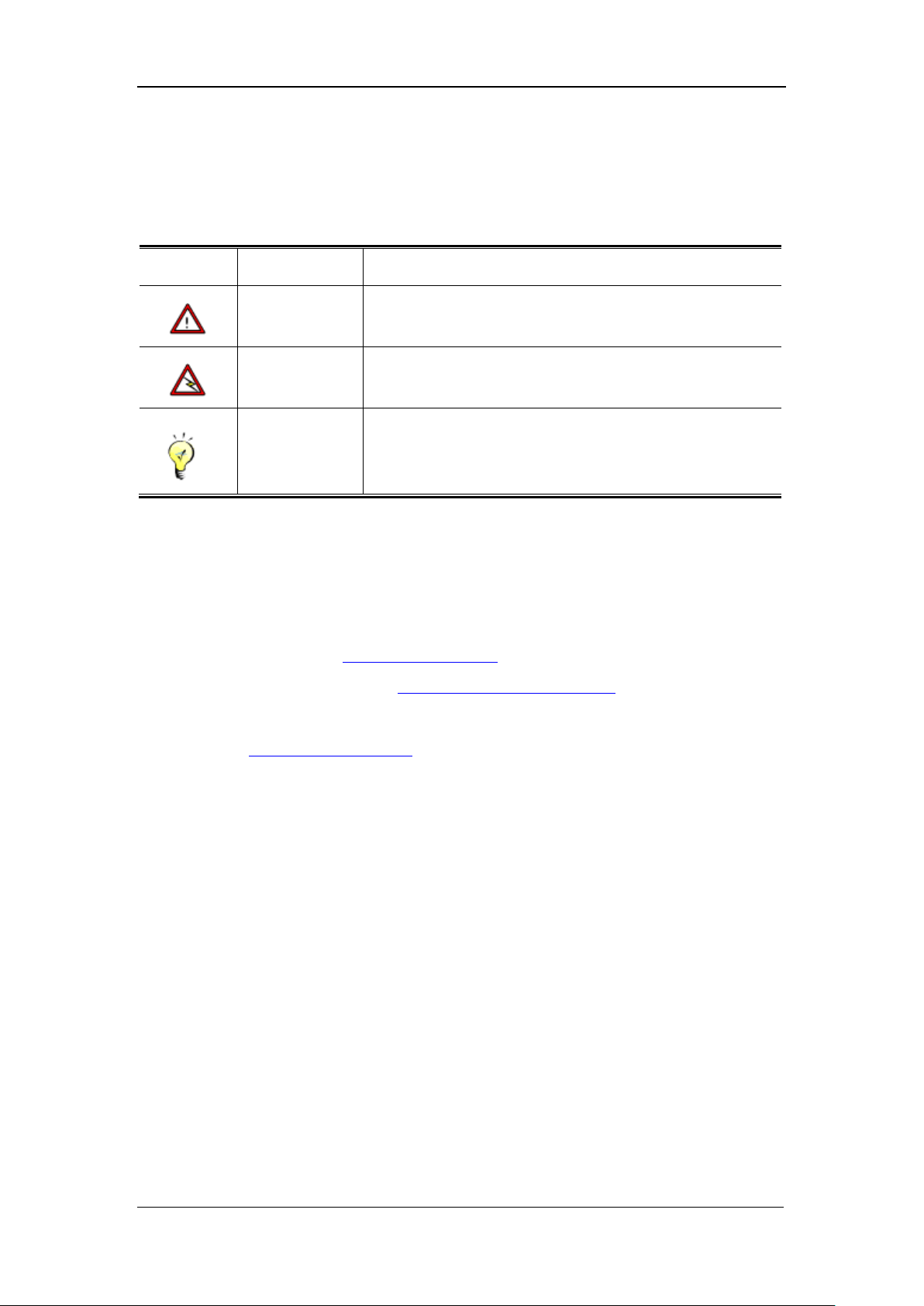
Caution
Indicates actions that could cause setting error, loss of data or
damage to the device.
Warning
Indicates actions that could cause injury to human body.
Note
Indicates helpful suggestion or supplementary information.
Symbol Conventions
This manual also adopts the following symbols to indicate the parts which need special attention to
be paid during the operation:
Technical Support
For technical support, use the following methods:
Go to our official website: http://www.sangfor.com
Go to our technical support forum: http://www.sangfor.com/cn/forum
Call 800-830-6430 (fixed-line phone) or 400-830-6430 (mobile or fixed-line phone)
Email us at: [email protected]
Acknowledgements
Thanks for using our product and user manual. If you have any suggestion about our product or
user manual, please provide feedback to us through phone or email. Your suggestion will be much
appreciated.
Page 13
SANGFOR IAM v2.1 User Manual
12
Chapter 1 IAM Installation
This chapter mainly describes the appearance of SANGFOR IAM series hardware gateway device
and the installation. After correct installation, you can configure and debug the system.
1.1. Environment Requirement
The SANGFOR IAM device requires the following working environment:
Input voltage: 110V-230V
Temperature: -10-50℃
Humidity: 5%-90%
To ensure long-term and stable running of system, the power supply should be properly grounded,
dustproof measures taken, working environment well ventilated and indoor temperature kept
stable. This product conforms to the requirements on environment protection, and the placement,
usage and discard of the product should comply with relevant national law and regulation.
1.2. Power
The SANGFOR IAM series device uses 110 ~ 230V alternating current (AC) as its power supply.
Make sure it is well-grounded before being provided with power supply.
1.3. Product Appearance
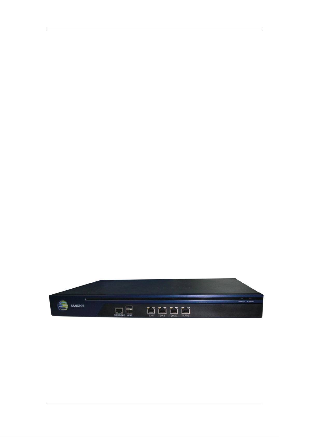
SANGFOR IAM hardware gateway device
Above is a SANGFOR IAM hardware gateway device. The interfaces or indicators on the front
panel from left to right are described respectively as follows:
CONSOLE Interface: Interface used for high-availability function (redundant system)
USB Interface: Standard USB port connecting to the peripheral device
LAN Interface: Network interface, to be defined as LAN interface
DMZ Interface: Network interface, to be defined as DMZ interface
Page 14

SANGFOR IAM v2.1 User Manual
13
WAN1 Interface: Network interface, to be defined as WAN1, LAN, or DMZ interface
WAN2 Interface: Network interface, to be defined as WAN2, LAN, or DMZ interface
POWER: Power indicator of IAM gateway device
ALARM: Alarm indicator of IAM gateway device (it keeps on for one minute
while the device is starting up)
Normally, the ALARM indicator keeps on lighting (in red) when the device is starting and
goes out in about one or two minutes, indicating successful startup of the device. After
startup, the ALARM indicator may flash, which means the device is writing logs; however,
if the ALARM indicator stays lighted for a long time and does not go out, please shut down
the device, and about 5 minutes later restart the device once again. If this situation remains
after restart, please contact our Customer Service to confirm whether the device is damaged.
The CONSOLE interface is only for debugging by technicians. The end users connect to the
device via the network interfaces.
1.4. Configuration and Management
Before configuring the device, please prepare a computer and make sure the web browser (for
example, Internet Explorer browser) of the computer can be used normally. Then connect the
computer to the IAM gateway device (in a same local area network) and configure the IAM
gateway on the computer over the established network.
1.5. Wiring Method of Standalone
Connect the power cable to the Power interface on the rear panel of the IAM gateway device and
switch on the power supply. The POWER indicator (in green) and ALARM indicator (in red) on
the front panel will be lighted. The ALARM indicator will go out one or two minutes later,
indicating the device runs normally.
Follow the instructions below to wire the interfaces:
Use standard RJ-45 Ethernet cable to connect the LAN interface to the local area network and then
configure the IAM gateway device.
Use standard RJ-45 Ethernet cable to connect the WAN1 interface with the networking device,
Page 15
SANGFOR IAM v2.1 User Manual
14
such as router, optical fiber transceiver, ADSL Modem, etc.
Use standard RJ-45 Ethernet cable to connect DMZ interface to the DMZ zone network. Generally,
the Web server and Mail server providing services to wide area network (WAN) are placed at the
DMZ zone. The IAM device provides secure protection for these servers.
Multi-line function of the IAM gateway device allows multiple Internet lines to be connected
in. You can connect the second Internet-access device to the WAN2 interface.
When IAM gateway device runs normally, the POWER indicator (in green) will keep on
lighting, and the WAN LINK and LAN LINK indicators (in orange) will keep on lighting.
The ACT indicators (in green) will flicker if there is data flow. The ALARM indicator will
be lighted only for about one minute due to system loading when the device is starting and
then go out, indicating successful startup of the device. If the ALARM indicator stays lighted
during startup, please switch off the power and restart the device. If it still keeps on lighting
and does not go out, please contact us.
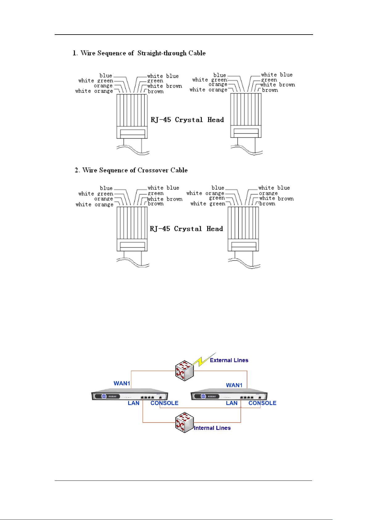
Please use straight-through cable to connect a WAN interface with the Modem, and crossover
cable to connect a WAN interface with the router. Use straight-through cable to connect the
LAN interface with the switch, and crossover cable to connect the LAN interface on the
device with the network interface on the computer. If connections cannot be established
while the corresponding indicator functions normally, please check whether the cables are
correctly used for connections. The differences between straight-through cable and crossover
cable are the wire sequences at both ends are different, as shown in the next figure.
Page 16
SANGFOR IAM v2.1 User Manual
15
Wire Sequences of Straight-through Cable and Crossover Cable
1.6. Wiring Method of Redundant System
If two SANGFOR IAM gateway devices are deployed to work in high availability mode (HA), the
wiring to the external network and internal network should be as shown in the following figure:
Use standard RJ-45 Ethernet cable to connect the WAN1 interfaces of the two IAM gateway
devices to a same switch (if multi-line function is applied, the wiring is the same while the WAN
interfaces of the two gateway devices should be ensured to be connected to a same external line);
Page 17

SANGFOR IAM v2.1 User Manual
16
then use a standard RJ-45 Ethernet cable to connect the IAM gateway device to other networking
device such as router, fiber optical transceiver or ADSL Modem, etc.
Use the Console cable (among the accessories) to connect the serial ports of the two IAM gateway
devices (through the CONSOLE interface).
Use RJ-45 Ethernet cable to connect the LAN interfaces of the two IAM gateway devices to a
same switch, and then connect the switch to the local area network switch with standard RJ-45
wire, connecting it to the local area network (LAN).
Having completed wiring, you have to switch on the power of the two IAM gateway devices and
then configure them. Device configuration of the HA system is the same with that of a single IAM
gateway device; you need only configure one of the IAM gateway device, and the other IAM
gateway device will synchronize and copy the settings automatically.
Page 18
SANGFOR IAM v2.1 User Manual
17
Chapter 2 Console
2.1. Web UI Login
IAM series gateway devices support secure HTTPS login, at standard HTTPS port. The login URL
address is: https://10.251.251.251
Log in through HTTPS to the WEB user interface (WEB UI) to manage the IAM gateway
device, the potential risks caused by interceptions during transmission can be avoided.
Having connected all the wires, you can go on to configure the SANGFOR IAM gateway device
through the WEB UI. Detailed procedures are as described in the following chapters.
Configure a valid IP address for the IAM gateway device. The IP address is of the 10.251.251.X
network segment (such as 10.251.251.100). Then type the default login IP address and port of the
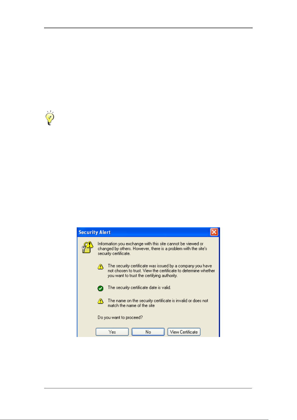
IAM device in the IE browser, https://10.251.251.251, and the following pop-up warning dialog
appears:
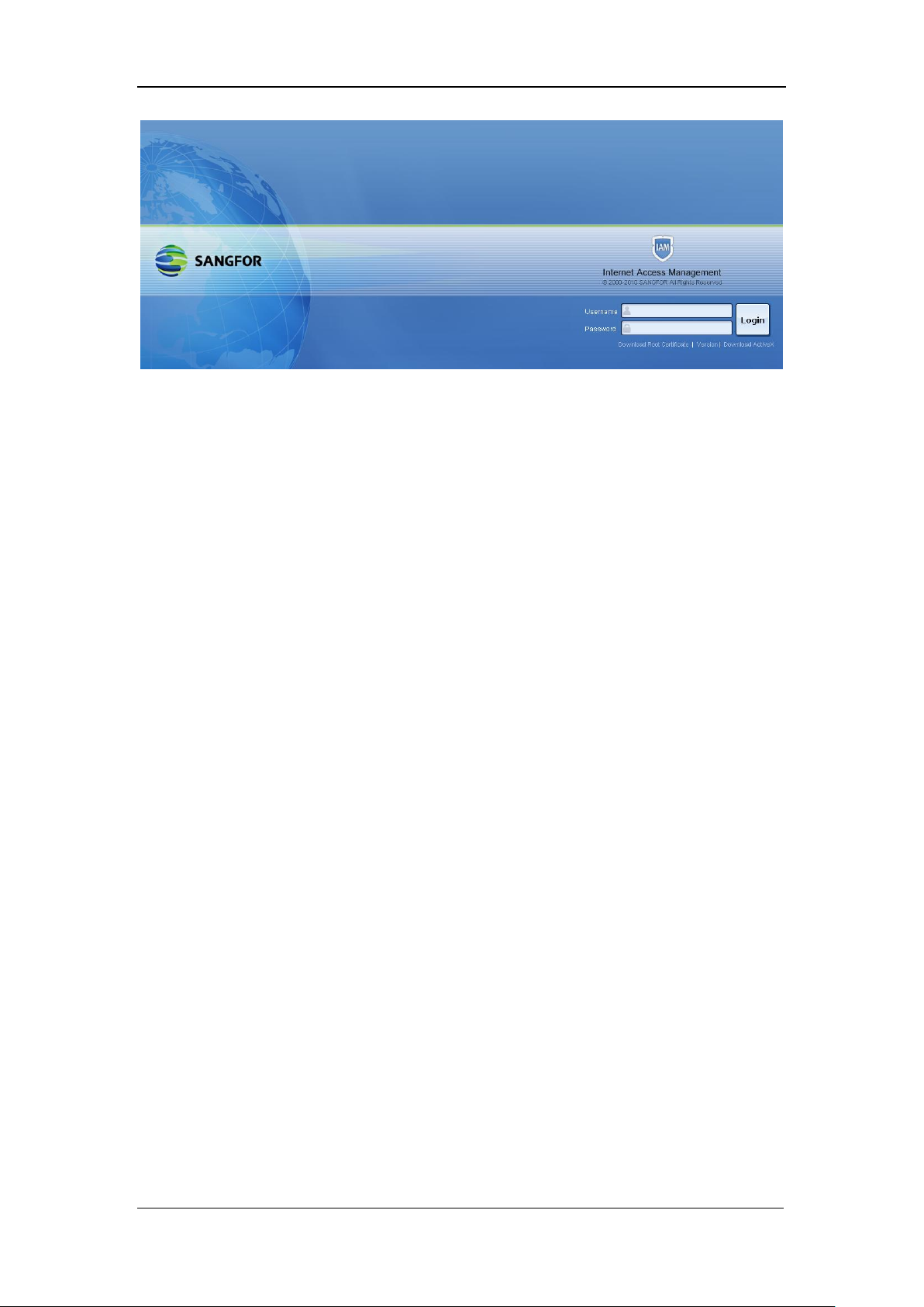
Click the <Yes> button and the following login interface appears:
Page 19
SANGFOR IAM v2.1 User Manual
18
Before login, you may be required to install the pop-up ActiveX control. Click “This site might
require the following ActiveX control: „sangfor dcweb‟ from Sangfor Technology Co., Ltd‟. Click
here to install…” > “Install ActiveX Control…” and then follow the instructions to finish
installation. If there is no prompt of installing the ActiveX control, click the <Download ActiveX>
link to manually download the ActiveX control, and follow the instructions to finish installation.
Enter the user name and password; click the <Login> button or press <Enter> key to log in to the
console of IAM gateway device. The user name and password are Admin by default.
If you want to view the version information, click the link <View Version>.
2.2. IAM Gateway Configuration
Logging in successfully, you will face the following function modules (left tree): [System],
[Object], [Firewall], [IAM], [Bandwidth Management], [Delayed Email Audit], [Internet Access
Audit], [Logs/Troubleshooting], [Security], [DHCP], [Wizard], etc.
In case there is a <OK> or <Finish> button on a configuration page, click it after
altering/configuring the parameters to save or apply the settings. This will not be illustrated again
in the subsequent parts in this user manual.
If you are to switch network interface (LAN interface and WAN-type interface) on the [Network
Interface] page, the network connection will be interrupted and system requires rebooting the IAM
system and re-login.
All the configuration pages have a <Help> link at the upper right corner. If help is wanted, click it
to view the brief description of the item.
Page 20
SANGFOR IAM v2.1 User Manual
19
Chapter 3 System Status
[System] covers the running status of the IAM gateway device. Detailed sections are [Running
Status], [Security Status], [License], [Gateway Mode], [Network Interface], [Date/Time],
[Administrators], [WEB UI], [Backup/Restore], [Reboot], [Auto Update], [Route], [Generate
Certificate], etc.
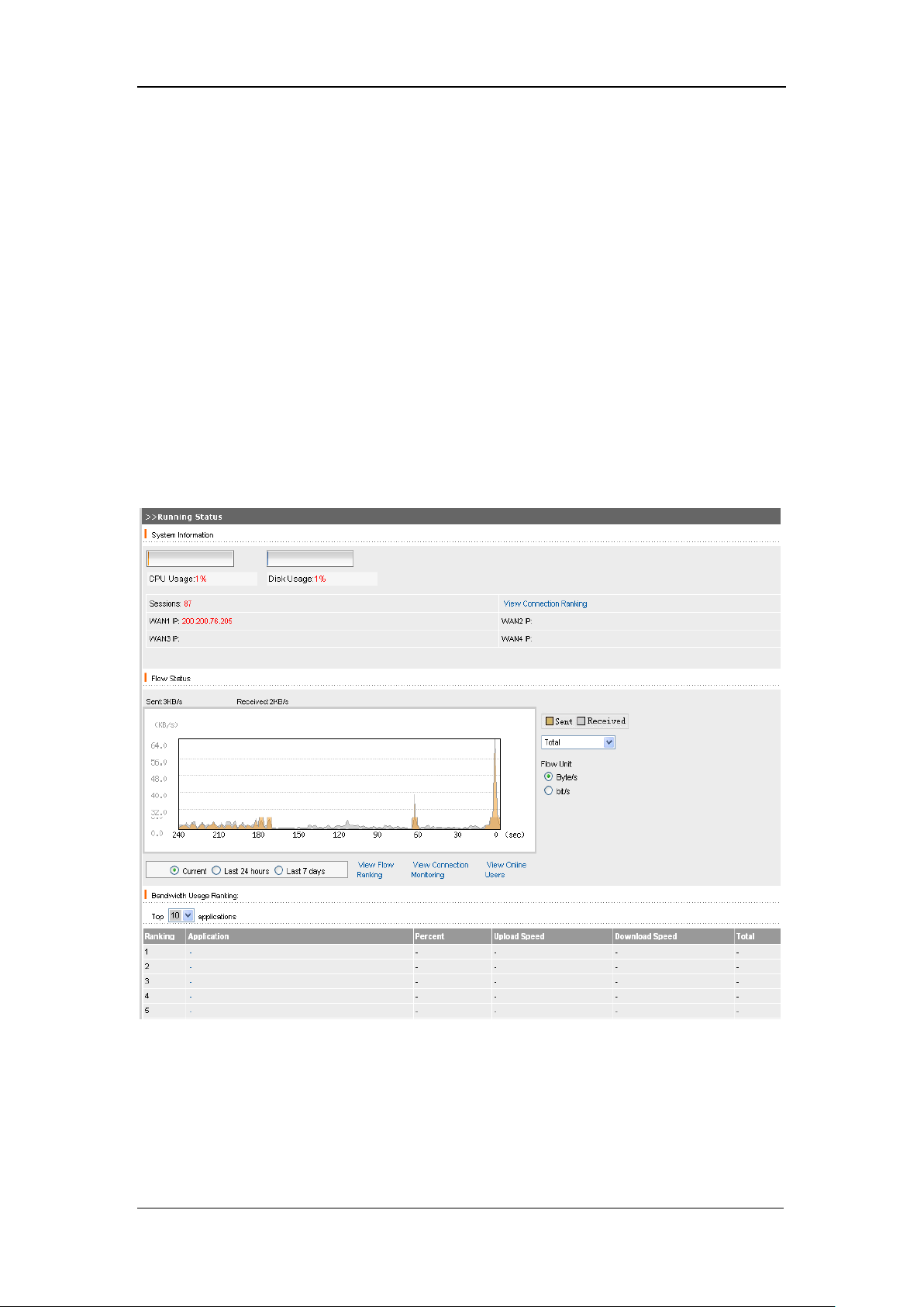
3.1. Running Status
[Running Status] provides the real-time status of the IAM gateway device, including [CPU usage],
[Disk Usage], [Sessions], [WAN IP], [Flow Status], as well as [View Connection Ranking], [View
Flow Ranking], [View Connection Monitoring] and [View Online Users].
[Note]: Displays various alarm, prompt information, etc.
[Flow Status]: Displays the received and sent data through the selected network interface card
(NIC) interface, etc.
<View Connection Ranking>: Click this link to view the ranking information of the active
Page 21
SANGFOR IAM v2.1 User Manual
20
connections of the IAM gateway device and the detailed connection information of an IP address.
For detailed introduction, please refer to Section 10.1.2 Connection Ranking.
[View Flow Ranking]: Click this link to view the uplink and downlink flow information of the top
10 rankings, the IP group to which this IP address belongs, traffic amount of the uplink and
downlink and of specific application. Click <Obtain> below the hostname, and you can get the
device name corresponding to this IP address. For detailed configuration, please refer to Section
10.1.1 Flow Ranking.
[View Connection Monitoring]: Click this link to view the connection information. Enter an IP
address and click the <Search> button, and you can get the current connection information of this
IP address. For detailed configuration, please refer to Section 10.1.3 Connection Monitoring.
[View Online User]: Click this button to view the online user(s) verified by IAM gateway device,
the login time and online duration of this user. The online user(s) can be forced to <Log Out> or
<Block For> some time. For details, please refer to Section 7.7 Online User.
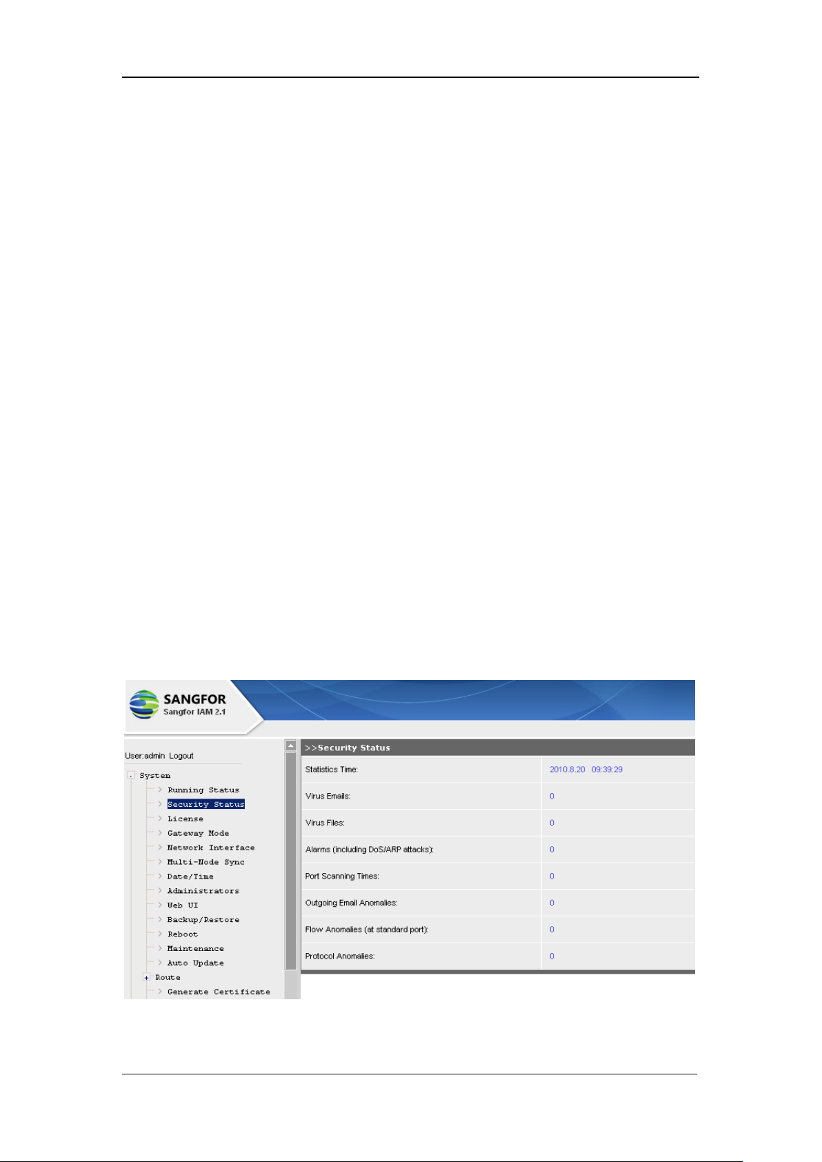
3.2. Security Status
[Security Status] displays the network security information and statistics of the IAM gateway
device, including [Statistics Time], [Virus Emails], [Virus Files], [Alarms] (including DoS/ARP
attacks), [Port Scanning Times], [Outgoing Email Anomalies], [Flow Anomalies] (at standard port)
and [Protocol Anomalies]. The related page is as shown below:
Page 22
SANGFOR IAM v2.1 User Manual
21
3.3. License
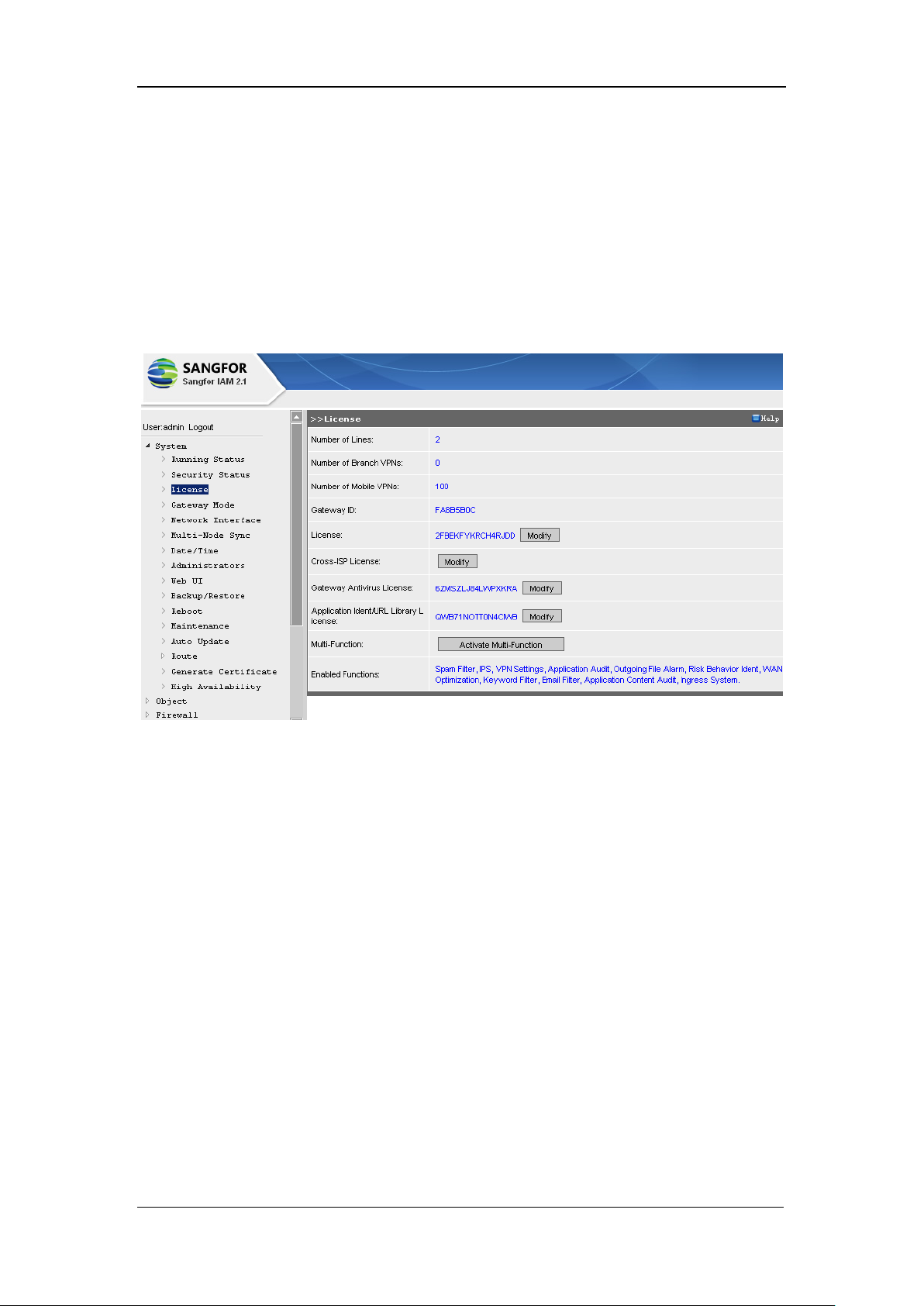
[License] includes [Gateway Antivirus license], [Application Ident/URL Library License] and
[Multi-Function] authentication, etc. It limits the number of connections from external networks,
of Branch VPN and Mobile VPN. A different license supports a certain number of lines and VPN
licenses. [Cross-ISP License], [Gateway Antivirus License], [Application Ident/URL Library
License] and [Multi-function] are optional.
[Cross-ISP License]: You can activate it so as to be able to establish VPN crossing ISPs.
[Gateway Antivirus License]: You can activate it to update the virus library of the antivirus
module.
[Application Ident/URL Library License]: You can activate it to update the expiry time of the
application identification library and URL identification library
[Multi-Function]: Click the <Activate Multi-Function> button followed; enter the serial number,
and then click the <OK> button to activate this function. Multi-function includes the following
functions: Spam Filter, IPS (Intrusion Prevention System), VPN Settings, Application Audit, Data
Center DKEY Search, Outgoing File Alarm, Risk Behavior Identification and SSL Identification.
[Enabled Functions] indicates this device has activated the listed functions.
Page 23
SANGFOR IAM v2.1 User Manual
22
3.4. Gateway Mode
[Gateway Mode]: Configures the working mode of the IAM gateway device. Four working modes
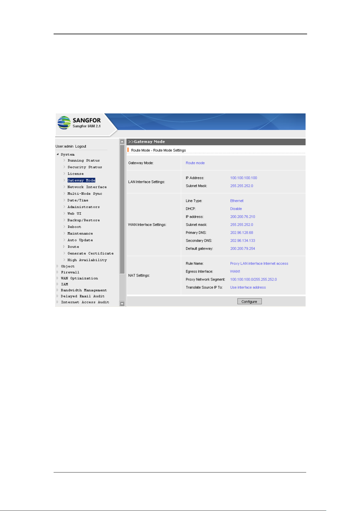
are selectable, namely, [Route Mode], [Bridge Mode], [Bypass Mode] and [Single-arm Mode].
The default configuration page of [Gateway Mode] is as shown below:
The current gateway mode and interface information are seen, below which is a <Configure>
button.
Click the <Configure> button to get into the next page and select the gateway mode to be switched
to.
Click the <Next> button and finish the rest required configuration options.
3.4.1. Route Mode
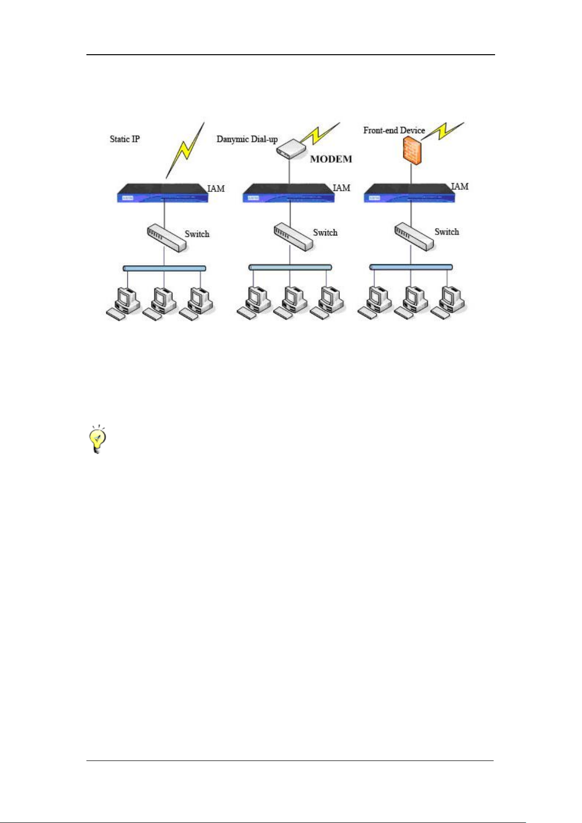
[Route Mode] takes the IAM gateway device as a route device. The IAM gateway device is
generally located at the exit of the LAN gateway, proxying the LAN users to get access to the
Internet; or the IAM gateway device is located below the router which then proxies the LAN users
to get access to the Internet.
Page 24
SANGFOR IAM v2.1 User Manual
23
The deployment is as shown in the following figure:
Under Route mode, the default gateway of all the LAN servers are directing to the LAN interface
IP of IAM gateway device, or to the layer 3 switch which then directs to IAM gateway device.
The requests for Internet access are forwarded through the NAT function or the routing function
of the IAM gateway device.
LAN interface and WAN interface should be configured with an IP address respectively that
is of different network segments.
If WAN2 interface (on the front panel of the IAM gateway device) is not used, you can define
WAN2 interface as a LAN2 or DMZ2.
If the LAN interface of the IAM gateway device is configured with 802.1Q-VLAN address,
the LAN can connect to the TRUNK interface of the layer 2 switch that supports VLAN, and
the IAM gateway device can forward data between different VLAN(with single-armed route),
besides, you can configure [LAN<->LAN] firewall rules. In other words, the access among
different VLAN ID (VID) can also be controlled if the LAN interface is configured with
802.1Q-VLAN address.
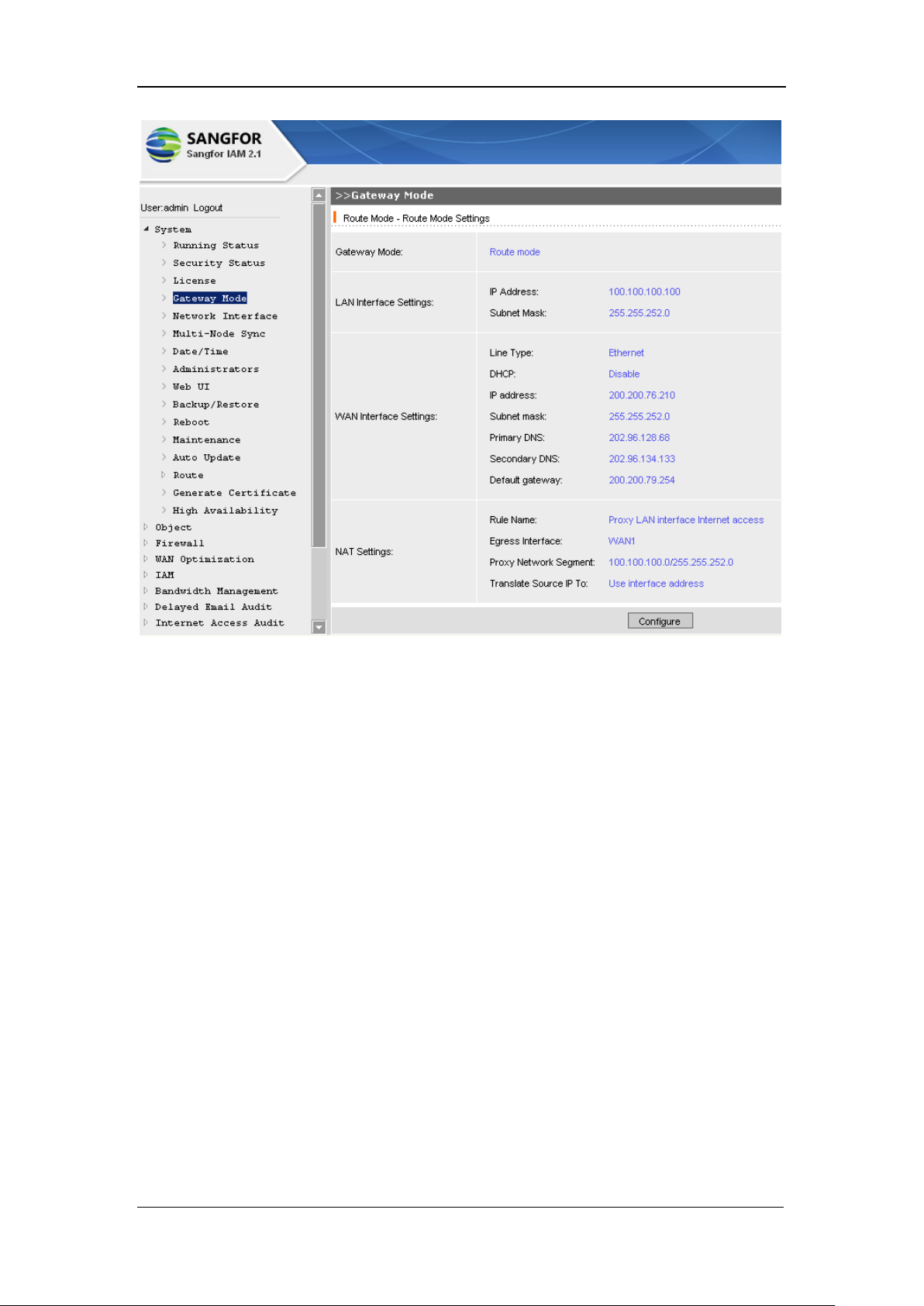
The [Route Mode Settings] are as shown in the figure below:
Page 25
SANGFOR IAM v2.1 User Manual
24
3.4.2. Bridge Mode
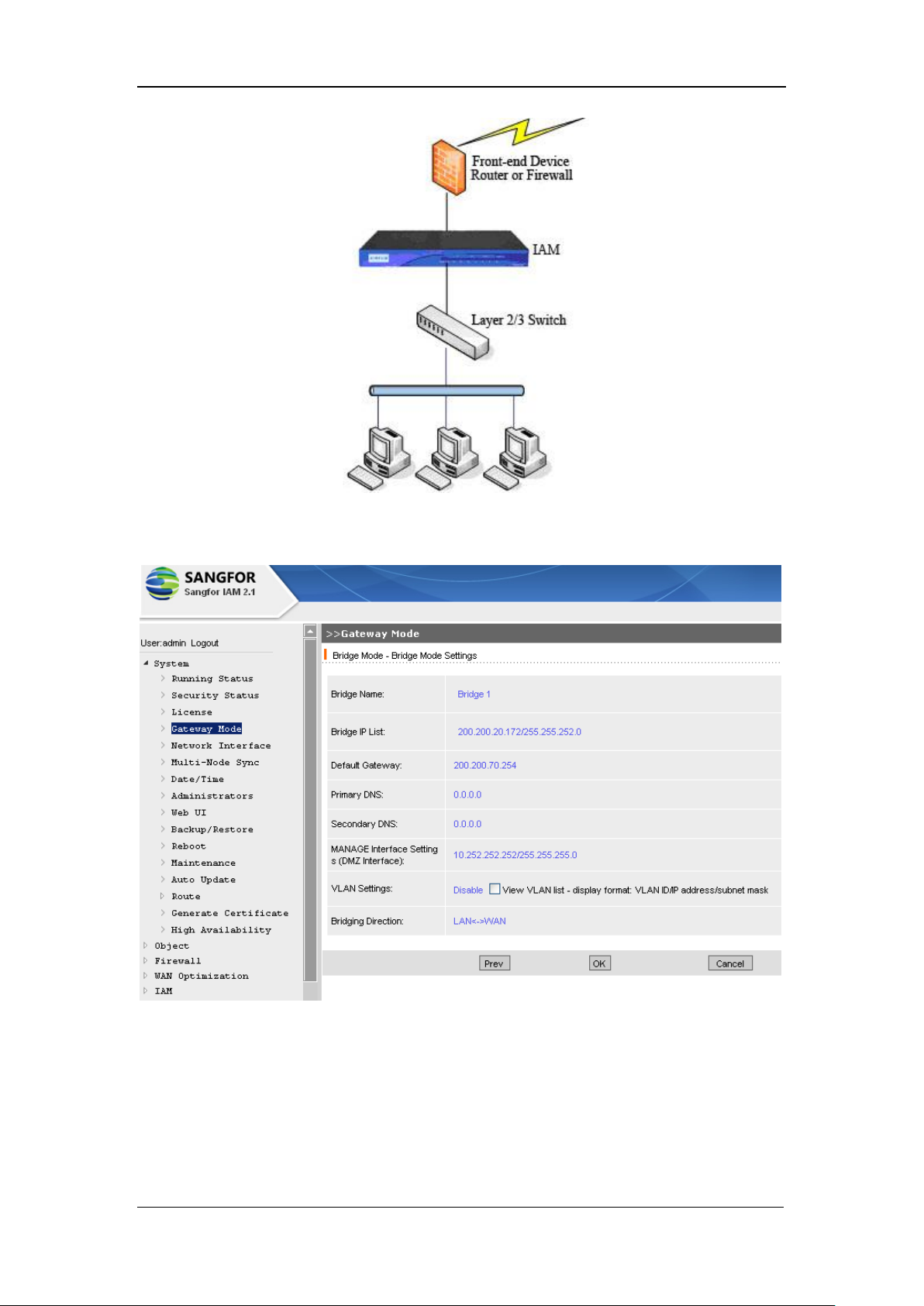
Bridge-mode deployment takes the IAM gateway device as a network cable with filtering function.
This mode is usually applied where the original topology of the network is inconvenient to be
altered.
The IAM gateway device locates between the original gateway and the LAN users, no change to
be made on the original gateway and the LAN users. It seems the original gateway and the LAN
server cannot feel the existence of the IAM device. It is what we call “Transparent” deployment
for the original gateway and the LAN users.
Bridge-mode deployment features traversing the data of the data link layer, absolutely transparent
to the users. Generally, if the IAM gateway is deployed as that shown in the following figure,
Bridge mode is recommended.
Page 26
SANGFOR IAM v2.1 User Manual
25
The configuration page is as shown below:
3.4.2.1. Bridge Mode: Multiple-Interface
Through bridging the interfaces of the IAM gateway device, we can establish multiple interfaces
for a bridge so as to create an environment supporting dual routes or dual lines of the network.
Page 27
SANGFOR IAM v2.1 User Manual
26
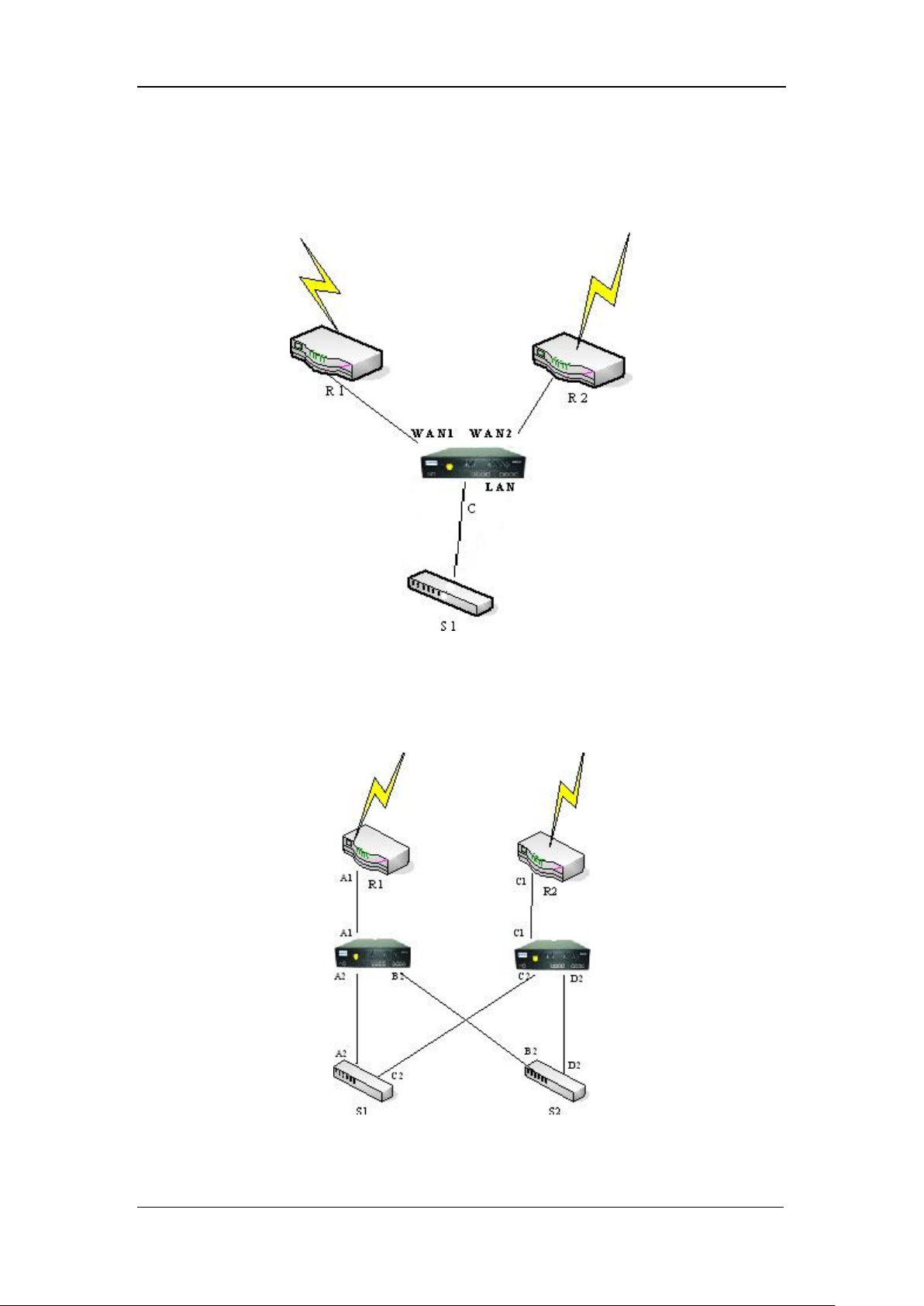
Environment examples for Bridge-mode deployment:
Environment 1: S1 connects to two external lines R1 and R2; an IAM gateway device (under
bridge mode) is then deployed to bridge R1 and R2 with S1.
Environment 2: In order to enhance the stability of the network and reduce single-node failure,
both the kernel switch and the router of local area network are in redundancy. Then we deploy two
IAM gateway devices into the networking, as shown in the following figure:
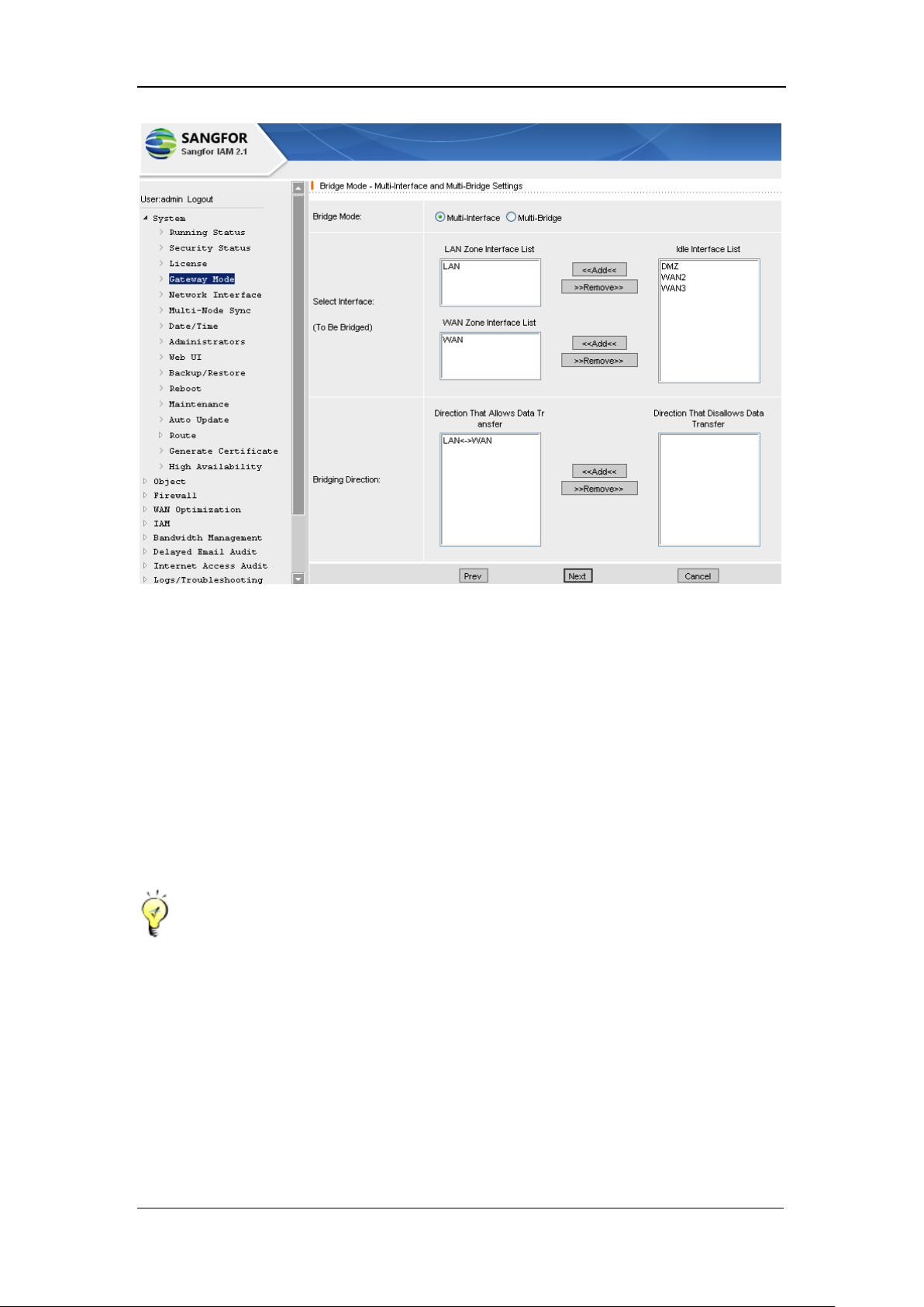
The configuration page of [Bridge Mode- Bridge Mode Settings] is as shown below:
Page 28
SANGFOR IAM v2.1 User Manual
27
[Gateway Mode]: Options are [Multi-Interface] and [Multi-Bridge].
[Select Interface]: Only available for [Multi-Interface].
[LAN Zone Interface List]: The selected interface will connect to local area network.
[WAN Zone Interface List]: The selected interface will connect to the outgoing device(s).
[Bridge Direction]: Defines the direction the data forwarded from and being forwarded to. In
association with the settings of the firewall rules, this item can allow or deny data transmission of
certain direction.
Differences between Multi-Interface and Multi-Bridge: Multi-Interface indicates one bridge
has several interfaces, and the IAM gateway device maintains only one MAC address table; while
Multi-Bridge regards that inside the IAM gateway device there are two independent bridges, each
individual bridge maintaining its own MAC address table, and the data of the two bridges cannot
be forwarded to each other.
Page 29
SANGFOR IAM v2.1 User Manual
28
3.4.2.2. Bridge Mode: Multi-Bridge
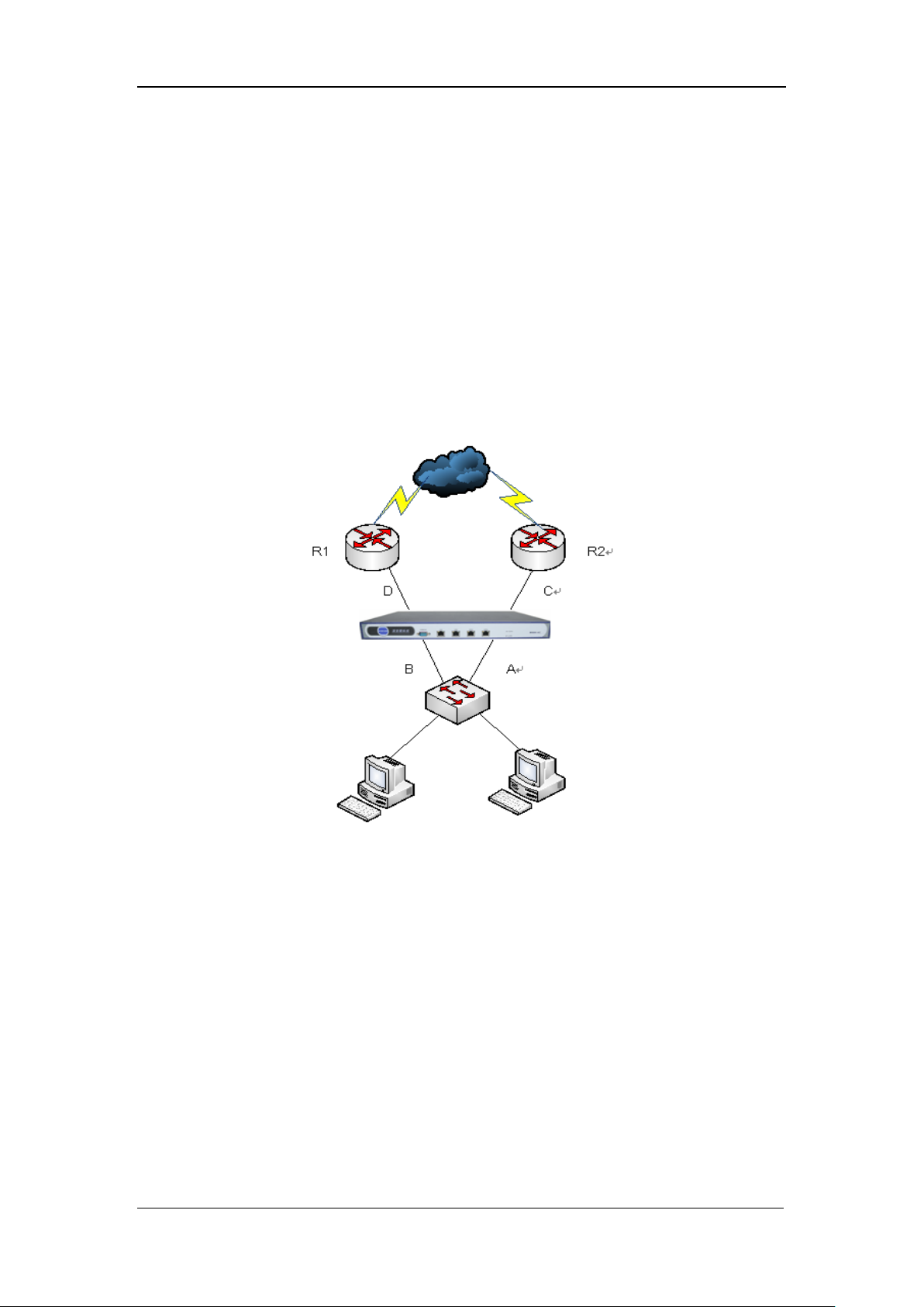
Environment for Bridge mode Multi-bridge:
In order to enhance the stability of the network and reduce single-node failure, both the kernel
switch and the router of local area network are in redundancy. Both R1 and R2 use VRRP protocol.
When the host is down, the alternate device enables the virtual IP and takes over the network.
Then we deploy the IAM device in Multi-Bridge Mode, data transmission directions are AC,
BD (corresponding to those in the Bridge list).
Detailed deployment is as shown in the following figure:
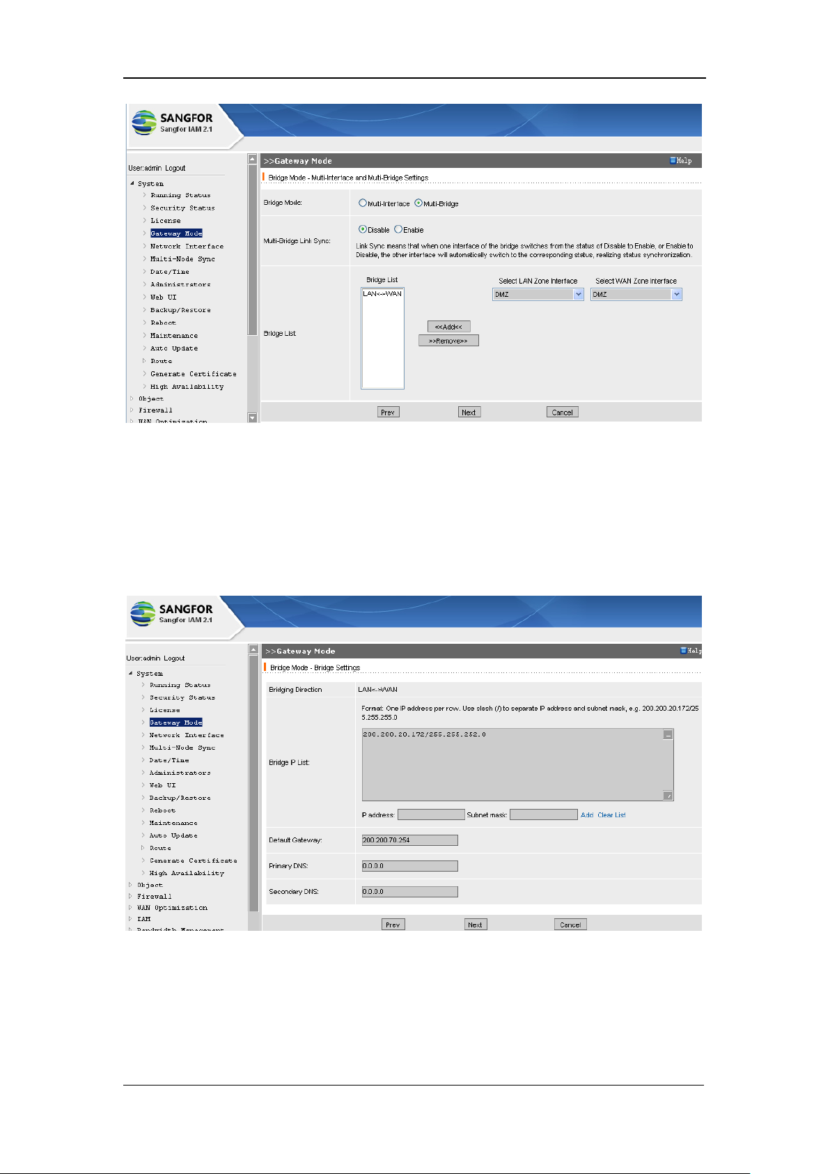
The configuration page is as shown below:
Page 30
SANGFOR IAM v2.1 User Manual
29
[Select LAN Zone Interface]: Select a LAN interface.
[Select WAN Zone Interface]: Select a WAN interface.
[Bridge List]: Defines the direction the data are forwarded to.
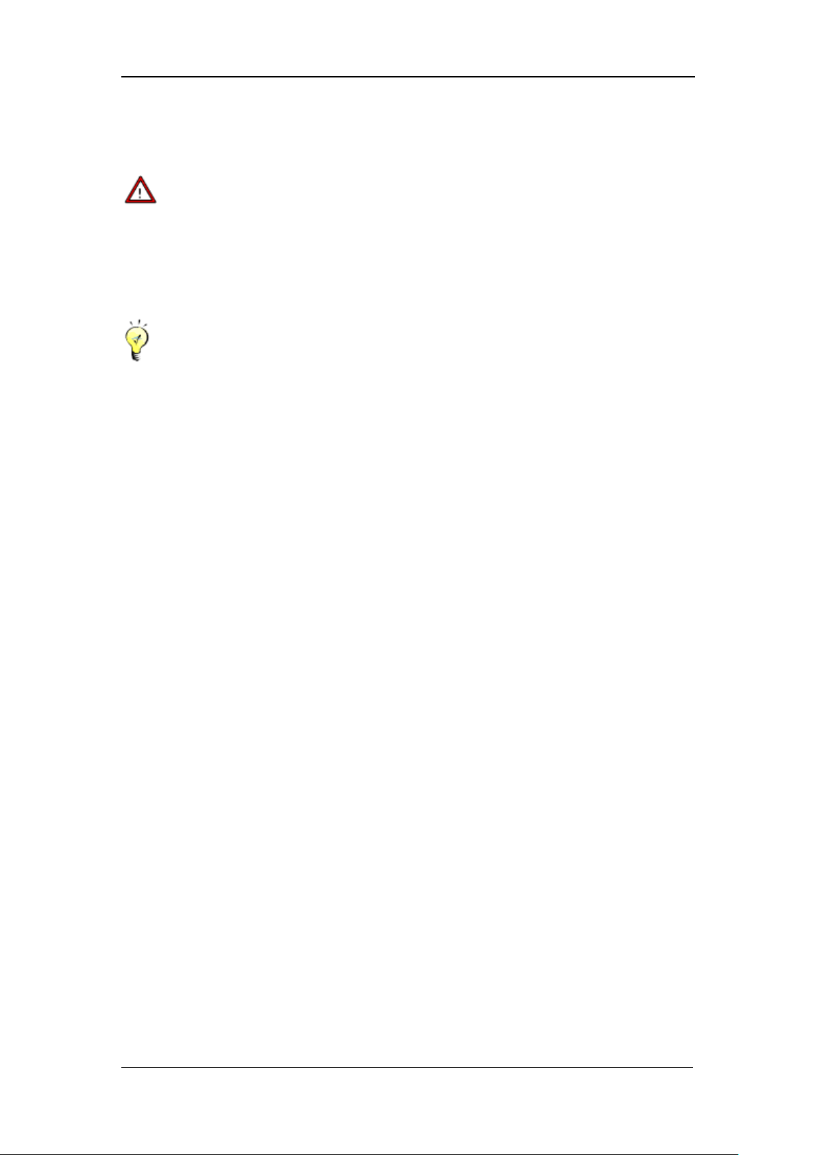
Click the <Next> button to get into the next page to configure the bridge, as shown below:
[Bridge Direction]: Indicates the direction of data transmission.
[Bridge IP List]: Based on [Bridging Direction], configures the IP interface of the LAN interface.
As to different bridging directions, the Bridge IP can be of a same network segment.
Page 31
SANGFOR IAM v2.1 User Manual
30
[Default Gateway]: Directs to the next hop interface IP of the bridge.
Under Multi-Bridge mode, you have to configure [Default Gateway] for each bridging
direction. [Default gateway] configures the default route of each bridge that is directing to the
gateway.
Under Bridge mode, gateway of the LAN PC needs no other change, but remains directing to
the original gateway, in other words, LAN PC directs to the LAN interface IP address of the
front-end device.
Under Bridge mode, the data for Internet access should be ensured to pass through IAM
gateway device, that is, the LAN user must not bypass the IAM gateway device and follow
the physical line of the original gateway to get access to the Internet.
As to data traversing, please ensure the WAN zone connects to the front-end routing device
and the LAN zone connects to the LAN switch. These two connections cannot be mixed up.
The data for Internet access transmitted from LAN zone to WAN zone can be monitored and
controlled.
“Transparency” of bridge-mode IAM gateway device is achieved at the data link layer (the
second layer of OSI), interfaces of the device are being bridged; the data of layer 2 and the
layers above can be traversed. This feature of the IAM gateway device enables the DHCP
service and the IP/MAC binding (of the original gateway) work.
NAT function is unavailable in Bridge mode.
Under Bridge mode, VPN module on the local IAM gateway device is unavailable.
If you want to enable the anti-virus function, email filter, etc., or if you want to have the URL
library, application identification library and virus library automatically updated, you need to
configure the [Bridge IP List], [Default Gateway] and [DNS], and make sure the IAM
gateway device itself to get access to the external network (you can implement “ping” to
check the availability of the external network).
If you want to enable the WEB authentication, ingress rule or other functions that need to be
redirected to the IAM gateway device and there are several LAN segments, you must add a
corresponding route, directing to the routing device.
If the computers of layer 2 switch have multiple network segments (instead of VLAN), the
gateway should also have IP addresses of multiple segments. If so, and you want to enable
the functions that need to be redirected to the IAM gateway device, such as anti-virus
function, email filter, ingress rule, WEB authentication, etc., the IP addresses of these
Page 32
SANGFOR IAM v2.1 User Manual
31
network segments should also be configured in [Bridge Mode] > [Bridge Settings ] page >
[Bridge IP List].
Under Bridge mode, the IAM gateway device supports VLAN TRUNK traversing; [Bridge
IP] can be IP address of 802.1Q-VLAN (which indicates the IAM gateway device can be
transparently connected to the main channel of VLAN TRUNK). To configure the
Bridge-mode deployment to support VLAN TRUNK, go to [Gateway Mode] > [Bridge
Mode] > [Bridge mode -VLAN Settings] page, as shown below:
Enter [VID], the VLAN [IP address] and [Subnet mask], and then click <Add>. If you have
enabled the functions that need to be redirected to the IAM gateway device, such as anti-virus
function, email filter, ingress rule, WEB authentication, etc., you have to configure this IP
address; otherwise, you can also leave the VLAN address list blank.
3.4.3. Bypass Mode
Without altering the networking, bypass-mode IAM gateway device can fulfill monitoring and
controlling, and can avoid disconnecting with the users. The IAM gateway device is connected to
the mirror port or the HUB, monitoring the overall local area network. Bypass mode plays no
influence on the network environment, and device failure will not disconnect the network.
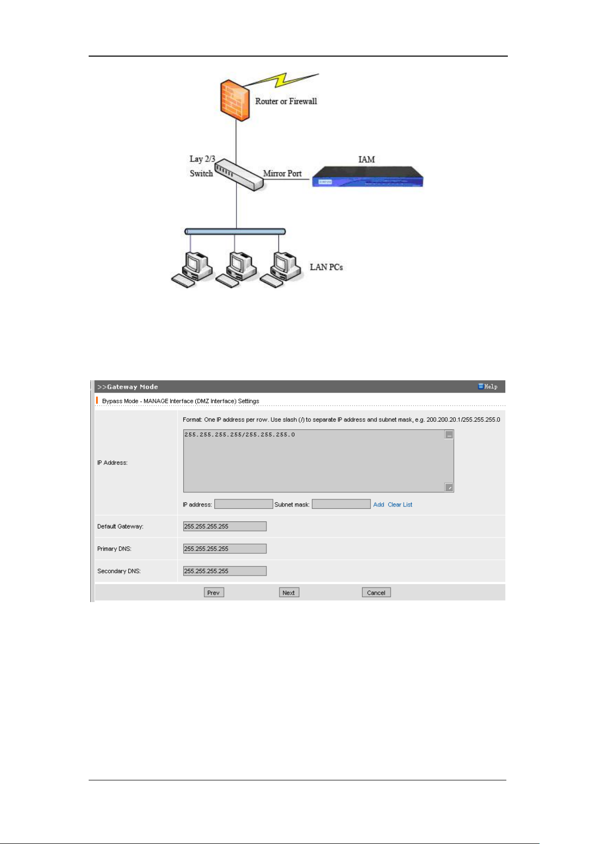
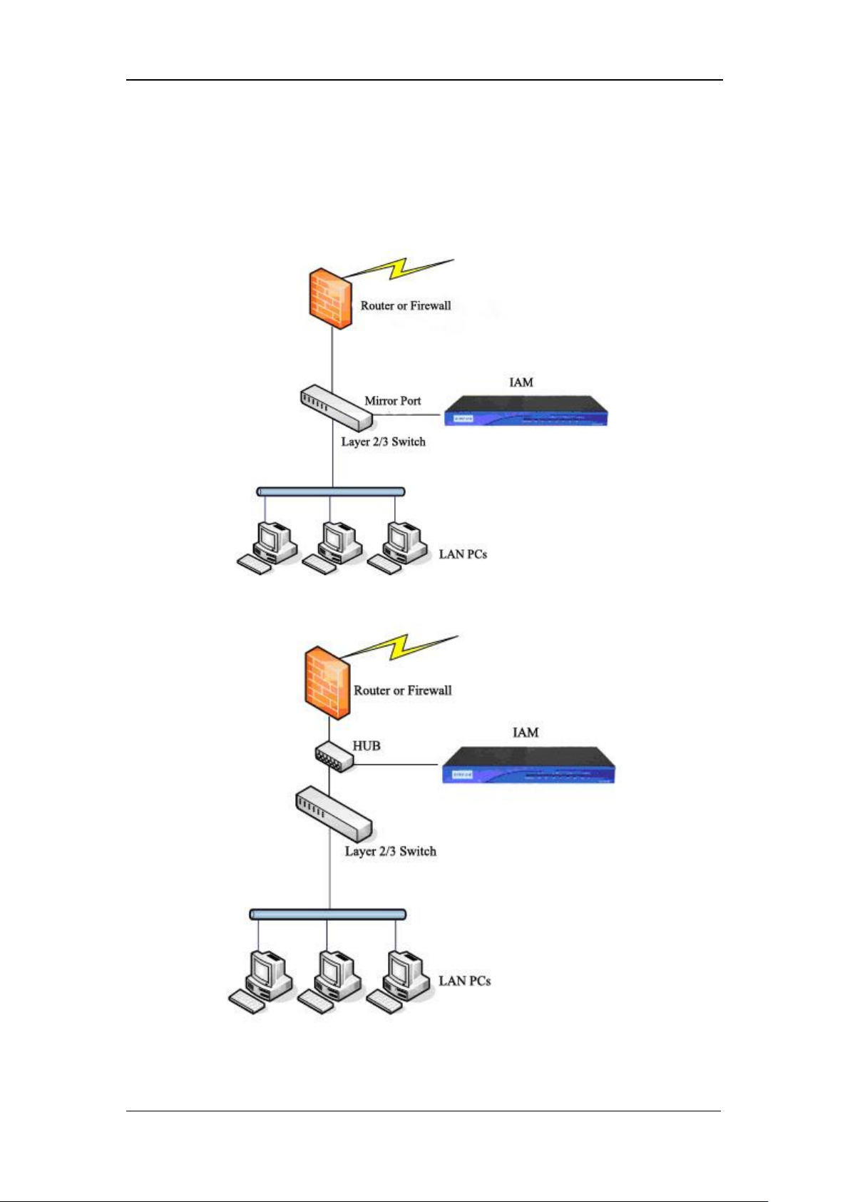
Typical topology of bypass-mode deployment is as shown below:
Page 33
SANGFOR IAM v2.1 User Manual
32
Under the [Gateway Mode] default configuration page, click <Configure> to enter the [Select
Gateway Mode] page.
Select [Bypass Mode] and click the <Next> button, then the following page appears:
[IP Address]: Configures the IP address of the MANAGE interface (DMZ interface).
Click the <Next> button to get into the next configuration page, as shown below:
Page 34
SANGFOR IAM v2.1 User Manual
33
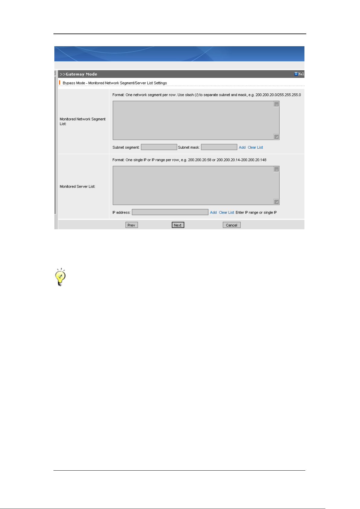
[Monitored Network Segment List]: Configure the network segments to be monitored.
In order to have the IAM gateway device connecting to the console or the client-updater, the
[IP Address] and [Default Gateway] must be configured and the network cable should
connect to the DMZ interface.
Since bypass-mode IAM gateway mode needs only one network cable to connect the LAN
interface or WAN1 (of the IAM device) to the HUB or mirror port of the switch, IAM
gateway device has no knowledge of which addresses are LAN addresses or which addresses
are WAN addresses, but regards the addresses in the [Monitored Network Segment List] as
LAN addresses. Access data sent to the Internet through these monitored addresses will be
recorded or controlled. However, IAM gateway device will default not to record the access
between two LAN PCs, which means, communication between any of the two addresses in
the [Monitored Network Segment List] will not be monitored.
Also, access data sent to the Internet through the server(s) of the [Monitored Server List] will
be recorded or controlled. Different from [Monitored Network Segment List], the access data
sent by the network segment(s) and passing through the LAN servers will be recorded.
The data irrelevant to the addresses or severs in the above two lists will not be monitored.
Page 35
SANGFOR IAM v2.1 User Manual
34
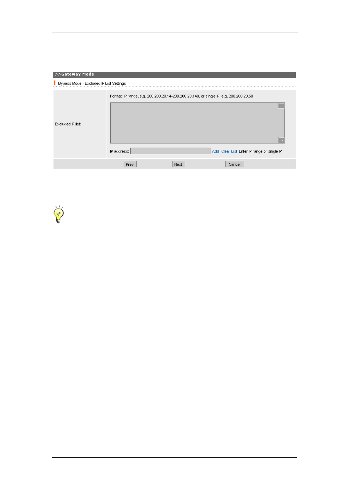
Click the <Next> button to continue the next step, configuring [Excluded IP List], as shown
below:
[Excluded IP List]: Access data requested by these excluded IP addressed will not be recorded.
Bypass mode deployment supposes that there is a HUB or a switch with mirror port. If the
switch has no mirror port, please connect a HUB to the front end of the switch.
Under Bypass mode, <View Flow Ranking> and <View Connection Ranking> are
unavailable.
Under Bypass mode, TCP control is fulfilled by sending „reset‟ packets through the DMZ
interface. Therefore, to achieve TCP control, all the „reset‟ packets sent through the DMZ
interface must be ensured to be received by the PC and the server of the public network.
Many functions are not available in bypass mode, such as VPN, DHCP and Ingress rule, etc.
Bypass-mode IAM gateway mode mainly plays a monitor role; control functions are not as
complete as those of Route mode or Bridge mode, for it can only restrict some TCP
connections, such as URL filtering, keyword filtering, email filtering, etc. No UDP
connection control can be done, such as P2P software, QQ login, etc.
3.4.4. Single-Arm Mode
Single-arm-mode deployment takes the IAM gateway device as a proxy. IAM gateway device can
fulfill monitoring and controlling, and can avoid disconnection of the users with the Internet. The
IAM gateway device is connected to the HUB or the mirror port of the switch, monitoring the
overall local area network. Single-arm mode requires no change on user‟s networking and plays
Page 36
SANGFOR IAM v2.1 User Manual
35
no influence on the network environment. If the device is down, you need only disable the proxy
service on the user‟s PC and to have it back into normal.
Typical topology of the single-arm mode is as shown below: failure will not disconnect the
network.
Under the [Gateway Mode] default configuration page, click <Configure> to enter the [Select
Page 37
SANGFOR IAM v2.1 User Manual
36
Gateway Mode] page.
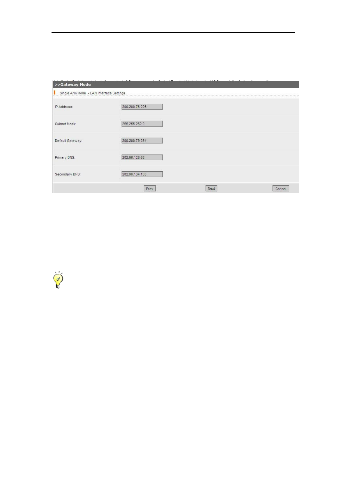
Select [Single Arm Mode] and click the <Next> button, then the following page appears:
[IP Address]: Configures the IP address of the LAN interface.
[Default Gateway]: Configures the gateway of the local area network, same with the gateway of
the LAN computer.
Click the <Next> button to get into the next configuration page, as shown below:
Under single arm mode, the gateway configured in the local area network need no change,
keeping directing to its original gateway.
To have the IAM gateway device work in single arm mode, you have to configure the [WAN
Optimization] > [Proxy Options].
VPN is not available for single arm mode.
Single mode mainly functions as a proxy. If a LAN user needs to get access to the Internet, it
need only have its computer‟s proxy server direct to the IAM gateway device, proxy server
address being set as the LAN interface IP address and the port as the proxy port (configured
in [WAN Optimization] > [Proxy Options] > [WAN Optimization] page).
Page 38
SANGFOR IAM v2.1 User Manual
37
3.5. Network Interface
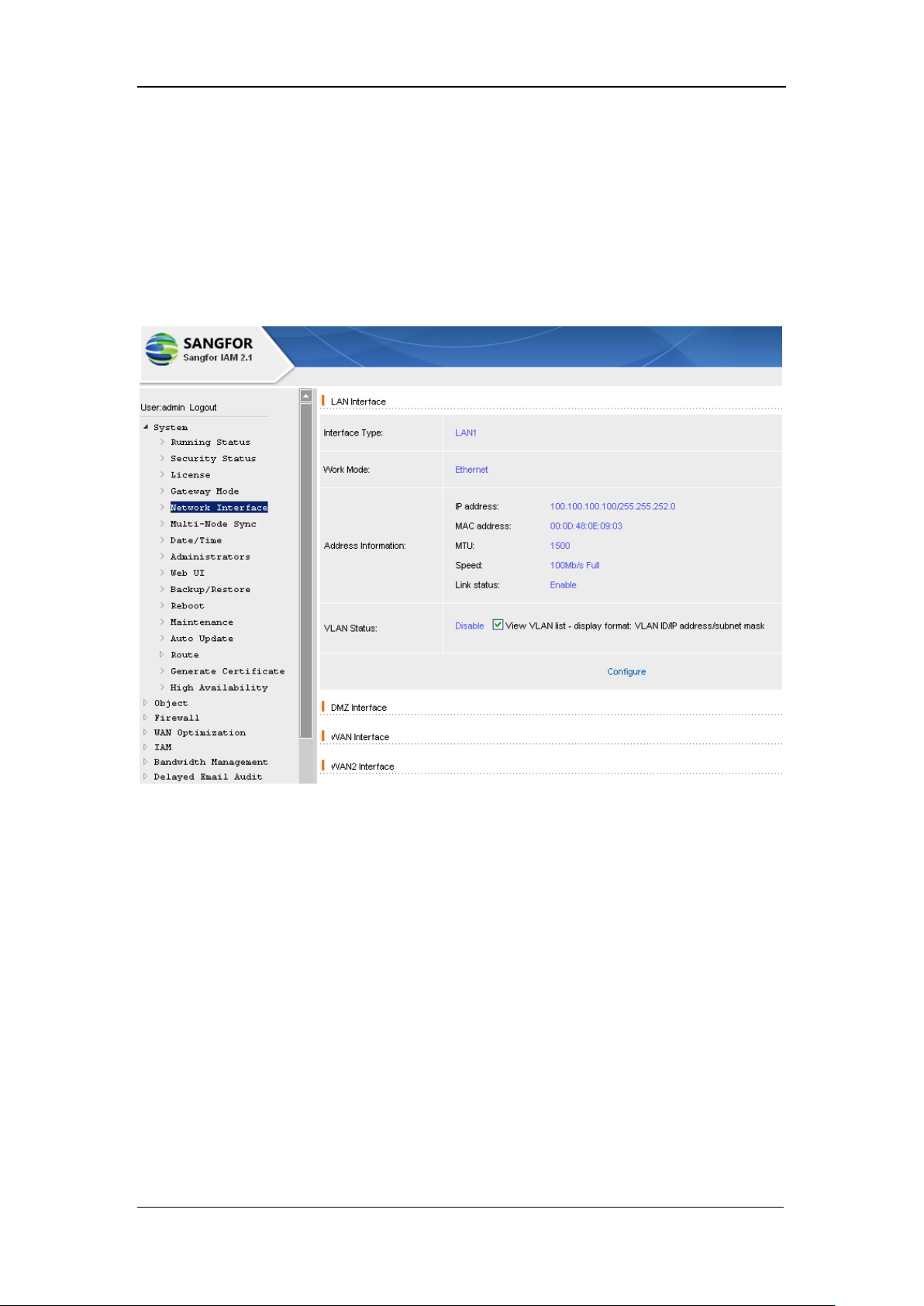
Under Route mode, you can configure the network interfaces on this [Network Interface] page. If
it is in Bridge mode, [Multi-bridge], you can also configure the bridge here. As to other gateway
modes, the network interfaces are configured in [System] > [Gateway Mode].
[Network Interface] default configuration page is as shown below:
[LAN Interface]: Displays the information of LAN interface. Click the <Configure> button to
enter the corresponding configuration page.
If you are to configure multiple IP addresses, you can add the IP addresses that are to be bound;
click the <Next> button to get into the next page.
[VLAN]: [Enable] or [Disable] VLAN.
[VLAN Address List]: If the interface of the switch that is connecting to IAM gateway device has
applied Trunk, then configure the IP address and VID (VLAN ID) for the VLAN at the LAN
interface.
The VLAN function supports VLAN (802.1Q) networking environment. If the LAN interface of
the IAM gateway device is configured with 802.1Q-VLAN address, the LAN can connect to the
TRUNK interface of the layer 2 switch that supports VLAN, and data of different VIDs can be
Page 39

SANGFOR IAM v2.1 User Manual
38
forwarded to each other (one-armed route); besides, you can configure [LAN<->LAN] firewall
rules to control the access among different VLAN IDs (VID).
[DMZ Interface]: Displays the information of DMZ interface. Click the <Configure> button to
enter the corresponding configuration page to configure the [IP address] and [Subnet mask].
[WAN Interface]: Displays the information of WAN interface. Click the <Configure> button to
enter the corresponding configuration page and configure the Internet access mode. If there is a
second external line, define WAN2.
[WAN2 Interface]: Displays the information of WAN interface. It can be defined as the second
external line, as well as a LAN interface or DMZ interface.
[WAN3 Interface]: Displays the information of WAN interface. It can be defined as the third
external line, as well as a LAN interface or DMZ interface.
[Multiline Settings]: Displays the line selection policy selected. Click the <Configure> button to
get into the configuration page and alter the line selection policy. Four policy options are available,
with explanations above them. [Multiline Settings] is suitable for the networking that consists of
multiple external lines.
3.6. Multi-Node Sync
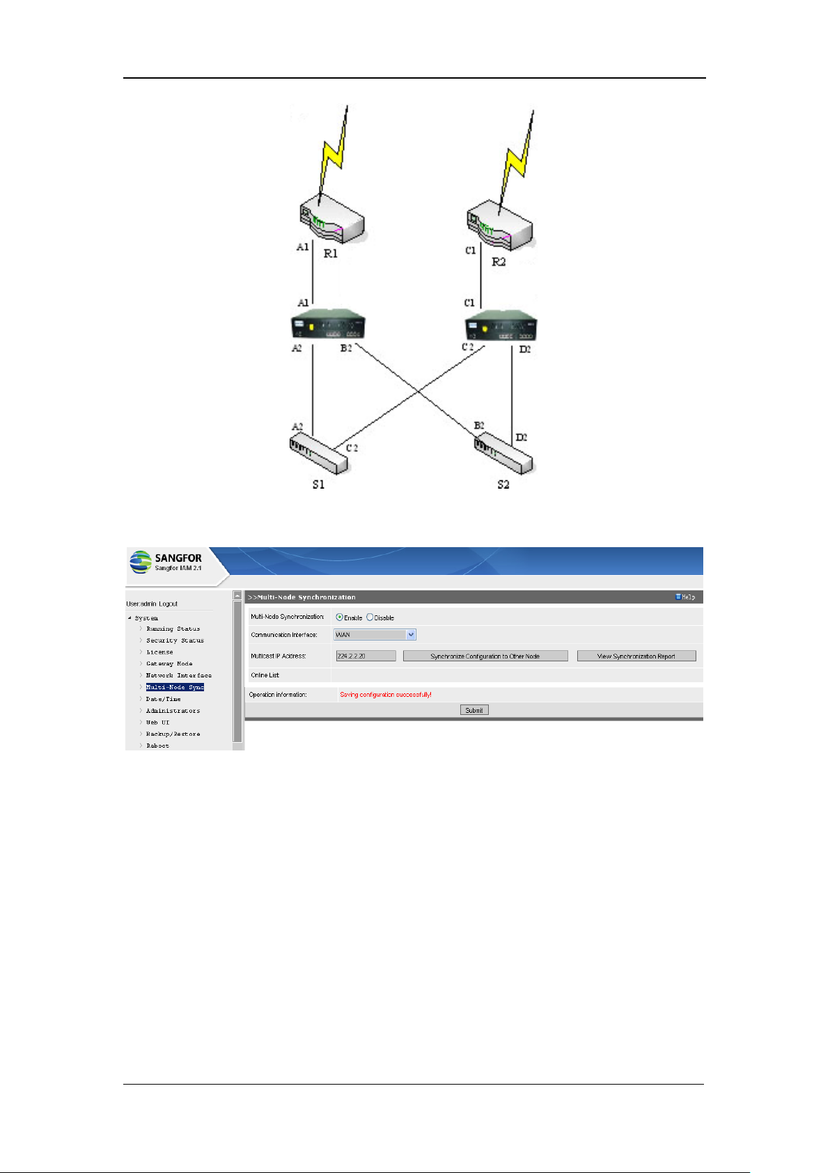
Environment for multi-node synchronization:
Two IAM gateway devices, A and B, are located in the local area network. Both of them work in
Bridge mode. Internet access requests of the LAN users pass through device A or B; user
information and access control policy are configured on IAM gateway device A.
Requirement: IAM gateway device A synchronizes IAM gateway B with the user information in
real time.
The deployment of multi-node system is as shown below:
Page 40
SANGFOR IAM v2.1 User Manual
39
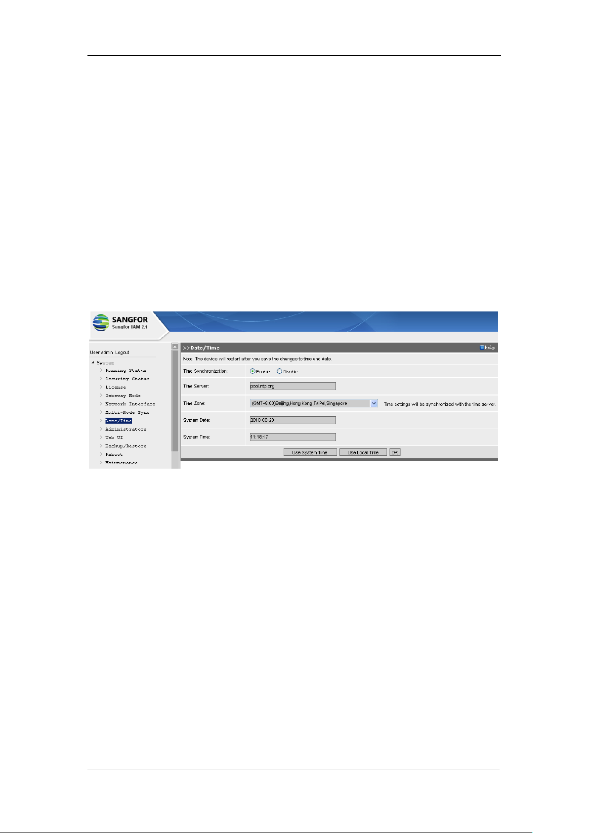
The [Multi-Node Synchronization] configuration page is as shown below:
[Multi-Node Synchronization]: [Enable] it and the user authentication information, user list, and
data of the internal identification libraries will be synchronized in real time.
[Communication Interface]: Configures the network interface used for the synchronization
between the IAM gateway devices. The communication interface can be any network interface
that can cross multicast packets to communication with each other. It is recommended to use an
idle network interface to connect them directly.
[Multicast IP Address]: Configures the multicast address used for synchronization between the
IAM gateway devices. The multicast can be any addresses of the multicast IP range. However, the
multicast IP addresses configured on the to-be-synchronized IAM gateway devices must be the
same.
Page 41
SANGFOR IAM v2.1 User Manual
40
[Online List]: Displays the IP addresses of the synchronization-related devices.
Having completed configuring the page, you have to click the <Synchronize Configuration to
Other Node> button to send synchronization signals to the other node (IAM gateway device); or
click the <View Synchronization Report> button to view the synchronization information.
3.7. Date/Time
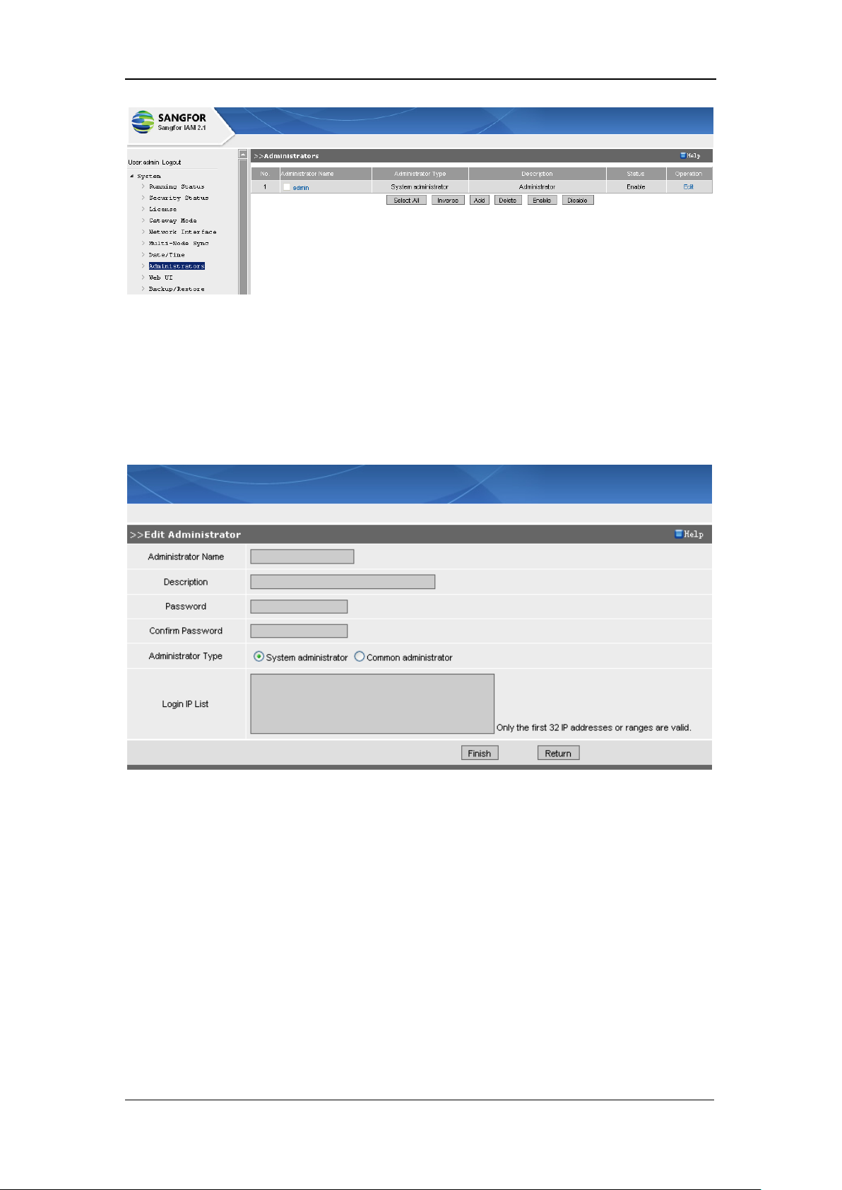
[Date/Time]: Configures the system date and time of the SANGFOR IAM hardware gateway
device. In addition to modifying the system time directly, you can configure a [Time Server] to
synchronize the time, and select a local [Time Zone].
The configuration page is as shown below:
<Use System Time>: Click this button to update the time of the IAM gateway device.
<User Local Time>: Click this button to update the system date/time of the IAM gateway device
with the date/time of the local PC with which you have logged in to the console of IAM gateway
device.
Having completed configuring this page, you have to click the <OK> button to save all the
settings.
3.8. Administrators
[Administrators] configures the console login user(s) who can manage the IAM gateway device
through the console.
Page 42
SANGFOR IAM v2.1 User Manual
41
<Select All>, <Inverse>: Click the corresponding button to select the needed administrator(s).
<Delete>, <Enable>, <Disable>: Click the corresponding button to delete, enable or disable the
selected administrator.
<Add>: Click this button to enter the [Edit Administrator] page, as shown below:
[Administrator Name]: Type in a unique name for this administrator to distinguish it from others.
[Description]: Type in a brief description for this administrator.
[Password]: Configures the login password for this administrator.
[Administrator Type]: Defines the role of the administrator, [System administrator] or [Common
administrator].
[System administrator] has all the privileges and can manage all the functions and user groups.
[Common administrator]‟s privileges of managing is defined in much more details. More
Page 43
SANGFOR IAM v2.1 User Manual
42
introductions are followed in this section.
[Login IP List]: Configures the IP address(es) with which administrator(s) can log in to the
console. You can type in a single IP address or IP range. One entry per line, maximum 32 entries
are allowed.
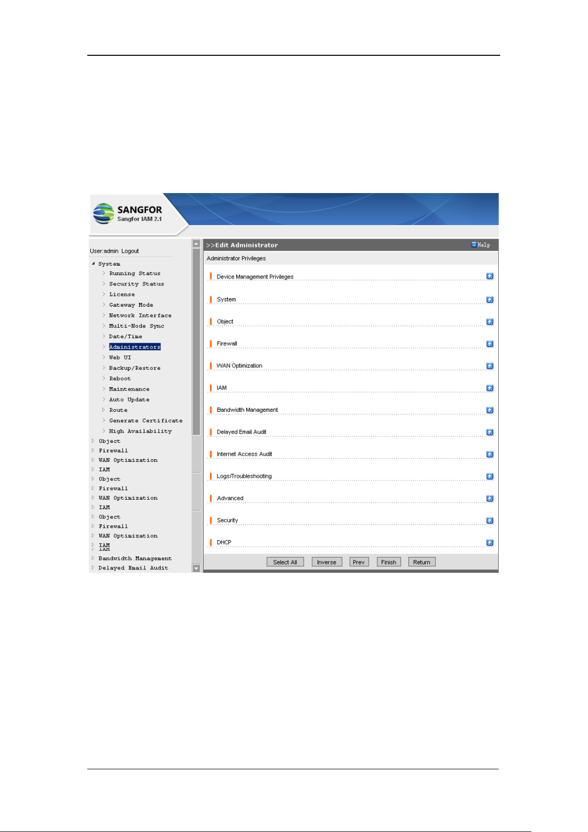
Privilege configuration of [Common Administrator] is as shown below:
Privileges of common admin are divided according to functions module, there are privileges on
[Device Management], [System], [Object], [Firewall], [IAM], [Bandwidth Management],
[Delayed Email Audit], [Internet Access Audit], [Logs/Troubleshooting], [Advanced], [Security]
and [DHCP].
[Device Management]: Configures the privileges the administrator have on managing the selected
user groups. Click the <Select> button to browse the organization structure of the IAM gateway;
click a user group or sub-group to add it to the list.
[Device Management Privileges] are, [View], [Member Management], [Policy Management],
Page 44

SANGFOR IAM v2.1 User Manual
43
[Delayed Email Audit] and [Data Center Audit].
[View]: Indicates this admin can only view the selected user or sub-group user information,
viewing the policy applied to its group and the online user list.
[Member Management]: Indicates this admin can manage and edit the selected group and
sub-group user. Once it is checked, it defaults with the [View] privilege and the privilege to block
online user(s).
[Policy Management]: Indicates this admin can manage the selected group and sub-group user.
Once it is checked, it defaults with the [View] privilege.
[Delayed Email Audit]: Indicates the admin can audit the delayed emails of the selected group(s).
It is applicable to different user groups.
[Data Center Audit]: Indicates the admin can log in to the internal Data Center to view the logs of
the selected group(s). The options of [Data Center Privileges] can be configured individually,
which are [System Management], [Customized Report] and [Intelligent Report].
As to [System] and [Object] function modules, you can check [Edit Privilege] and [View
Privilege].
[Policy Management] only allows the administrator to edit the association relationship
between the group/user and the po1icy. The policy itself cannot be modified, unless the
admin is the administrator who has created this policy or a system administrator.
If an administrator has neither the privilege to view nor the privilege to edit a certain function
module, this module will not display on the left tree of the console, in other word, it is
unavailable.
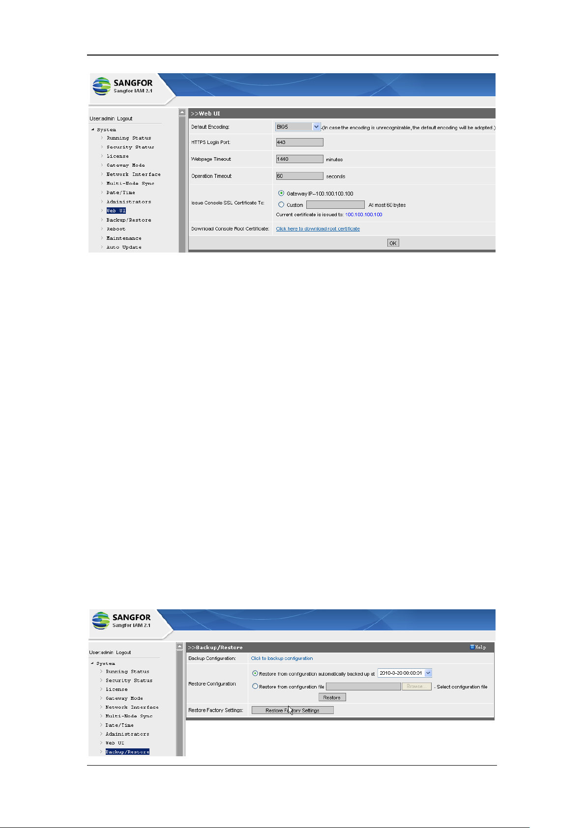
3.9. WEBUI
[WEB UI] configures the [Default Encoding], [HTTPS Login Port], [Webpage Timeout],
[Operation Timeout], [Issue Console SSL Certificated to], [Download Console Root Certificate].
The configuration page is as shown below:
Page 45
SANGFOR IAM v2.1 User Manual
44
[Default Encoding]: Select an option and the unrecognizable codes of the monitored data will be
handled as this code.
[HTTPS Login Port]: Configures the port of HTTPS protocol for logging in to the WEB UI. It is
443 by default.
[Webpage Timeout]: If there is no operation on the console during this time interval, the console
user will automatically log out the console.
[Operation Timeout]: If a page fails to open during this time interval, the system will think it times
out and will not try to open this page again.
[Issue Console SSL Certificated To]: Configures the IP or domain name to which the SSL
certificate of logging in to the console is issued.
[Download Console Root Certificate]: Click the link to download the SSL certificate of the
console. Having the PC installed this certificate, the alarm prompt requesting for SSL certificate
(when you are logging in to the console) will disappear.
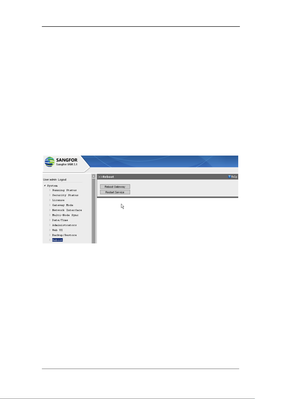
3.10. Backup/Restore
Page 46
SANGFOR IAM v2.1 User Manual
45
[Backup Configuration]: Click the link <Click to backup configuration> to download the
configurations to the local computer and to backup them.
[Restore from configuration automatically backed up at some time]: Select the time when the
configuration file is backed up. The backup configurations will replace the present ones. Generally,
the configuration file will be backed up for 7 days.
[Restore from the configuration file]: Click the <Browse> button; select and upload a backed up
configuration file, and then click the <Restore> button to have the backed up configuration replace
the present one.
3.11. Reboot
You can [Reboot Gateway] or [Restart Service] on this page, as shown below:
3.12. Maintenance
[Maintenance]: Defines whether to allow remote login through external network interface,
whether to [Auto Upload Unknown URL], whether to [Auto Report System Error] and whether to
[Auto Report Unknown Application].
Page 47
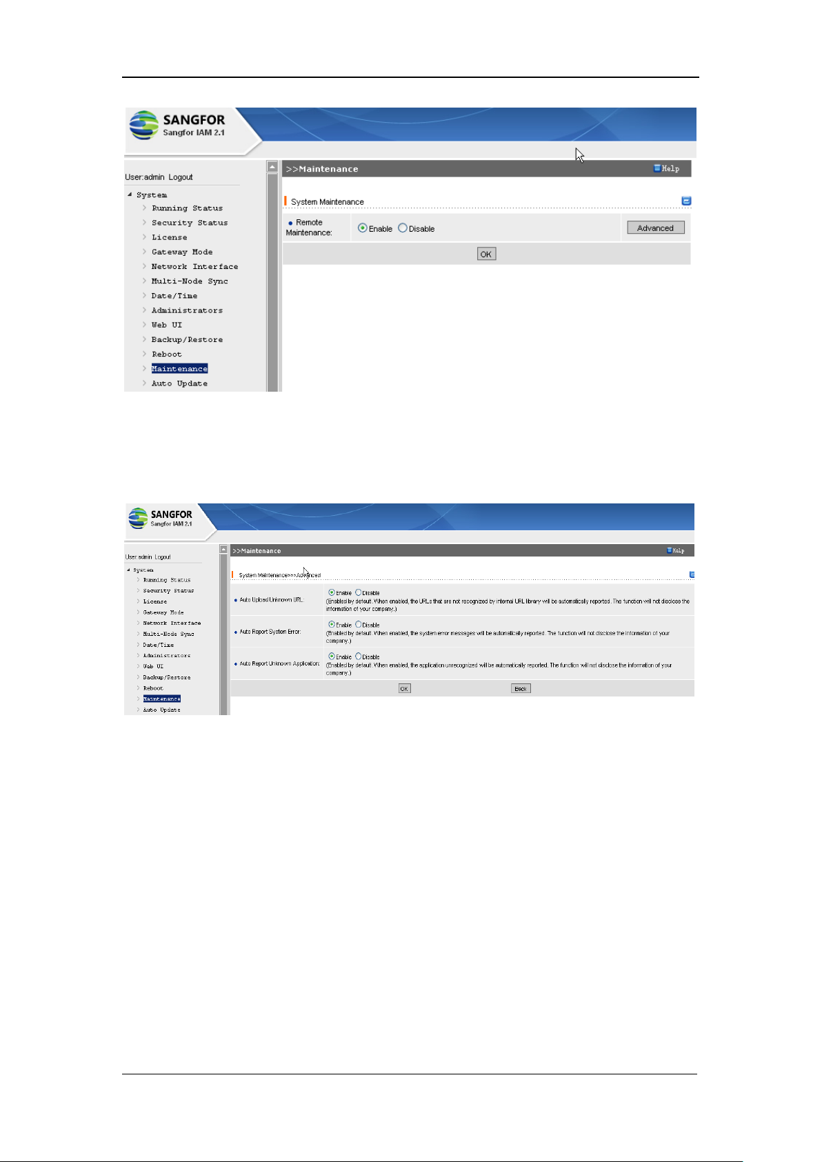
SANGFOR IAM v2.1 User Manual
46
Under the default configuration page, click the <Advanced> button to enter the [System
Maintenance] > [Advanced] page and configure [Auto Upload Unknown URL], [Auto Report
System Error] and [Auto Report Unknown Application], as shown below:
[Auto Upload Unknown URL]: Select [Enable] and the unknown URL found during using the
IAM gateway device will be automatically uploaded.
[Auto Report System Error]: Select [Enable] and the anomaly information found during using the
IAM gateway device will be automatically uploaded.
[Auto Report Unknown Application]: Select [Enable] and the unknown application information
found during using the IAM gateway device will be uploaded.
3.13. Auto Update
[Auto Update]: Configure the update options of internal [Virus Library], [URL Library], [Gateway
Firmware], [Application Ident], [Ingress Rule]. The configuration page is as shown below:
Page 48
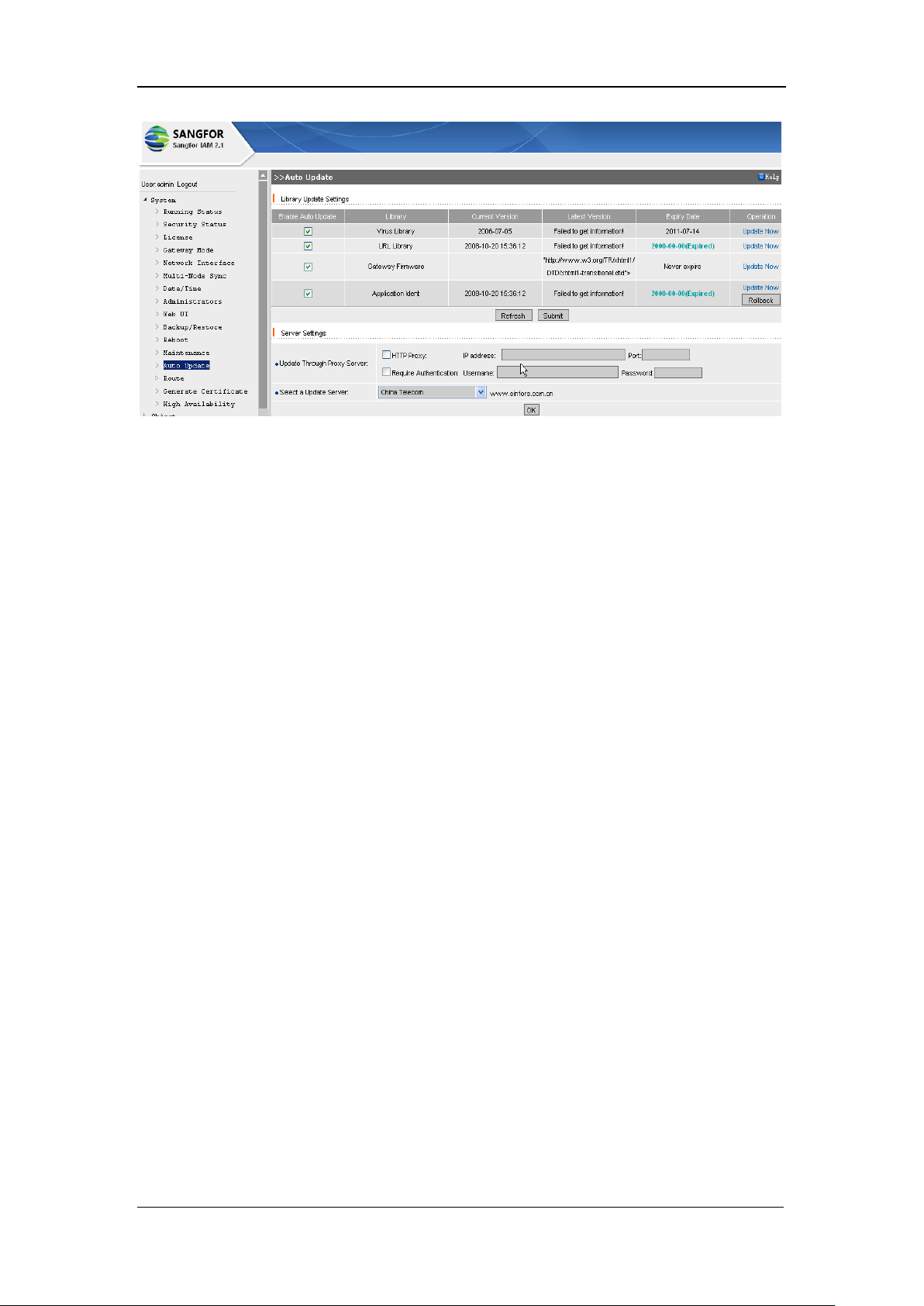
SANGFOR IAM v2.1 User Manual
47
[Enable Auto Update]: Check the corresponding item to automatically update the internal library.
<Update Now>: Click this button to immediately update the corresponding library that has not
been expired.
<Rollback>: Click this button to cancel the previous update of the corresponding library, and the
rules library will recover to the previous version of library.
To update the library, the IAM gateway device should be ensured to connect to the Internet. If the
IAM gateway device cannot access the Internet, you then need to configure [HTTP Proxy] options
in [Server Settings] (provided there is HTTP proxy), so as to ensure the IAM gateway device can
access the Internet smoothly and update the corresponding rules.
[HTTP Proxy] requires server [IP address] and [Port]; [Require Authentication] requires
[Username] and [Password].
To ensure update speed, select an update server. Generally, the update process will go more
quickly if the ISP server of the update server is the same with that used by the IAM gateway
device.
3.14. Route
[Route] covers [Policy Routing] and [Static Routing], and mainly configures the route related to
the IAM gateway device.
3.14.1. Policy Routing
SANGFOR IAM gateway device allows you to configure [Policy Routing]. Policy routing is
Page 49
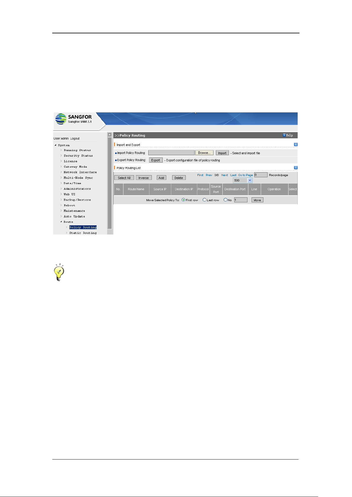
SANGFOR IAM v2.1 User Manual
48
mainly used when IAM gateway connects to multiple external lines. Through configuring the
source IP, destination IP, source port, destination port, protocol, etc., the policy-based route will be
created. Therefore, which external line is the outgoing line to the external network is selected
according to the manually-created policy.
The [Policy Routing] configuration page is as shown below:
[Policy Routing List]: Displays the existing policy-based routings.
If there are multiple applicable policy routings, the upper policy routing has higher priority to
be matched.
Click <UP> or <Down> to move up or move down the routing respectively; or [Select] an
existing policy routing, and then select [First row] or [Last row] or [No.] to move this rule to
top or bottom or to a specified row.
Click the <Add> button to enter the [Edit Policy Routing] page, as shown below:
Page 50
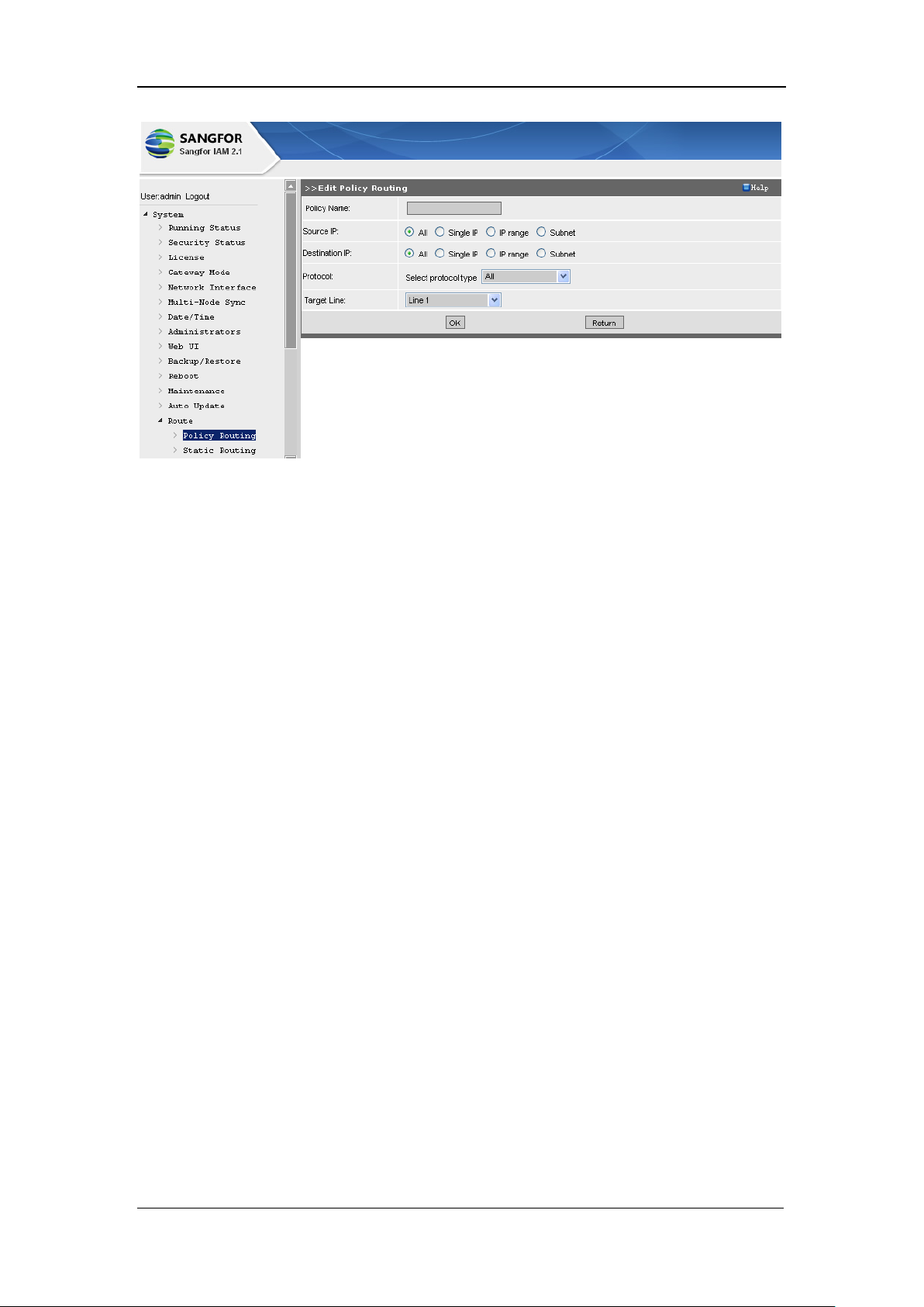
SANGFOR IAM v2.1 User Manual
49
[Policy Name]: Type in a unique name for this policy-based routing to distinguish it from others.
[Source IP], [Destination IP]: Configures the source IP, destination IP of the data packet on which
this policy routing applies. Four options are available, namely, [All], [Single IP], [IP range] and
[Subnet].
[Protocol]: Select a protocol for data packet transmission, [All] protocol, [TCP], [UDP], [ICMP]
or [Others]. As to [TCP] and [UDP] protocol, you have to configure [Source Port] and
[Destination Port]; for [Others] option, you have to enter [Protocol Number].
[Source Port], [Destination Port]: Configures the source port and destination port of the data
packet on which this policy-based routing is applied.
[Target Line]: This target line is the outgoing line of the data packet if all the conditions
configured above are matched.
Configuration Example of Policy Routing
Provided the IAM gateway device has two external lines. Line 1 is of CHINA NETCOM, Line 2
is of CHINA TELECOM. IP range of CHINA TELECOM is 221.199.32.0/20. We design a routing
based on [Destination IP] 221.199.32.0/20, [Destination Port] 80, all the data packet passing
through the [Target Line] Line 2.
To achieve traffic control of Internet access, we need to configure a policy routing rule. Specific
steps and settings are as shown below:
Page 51
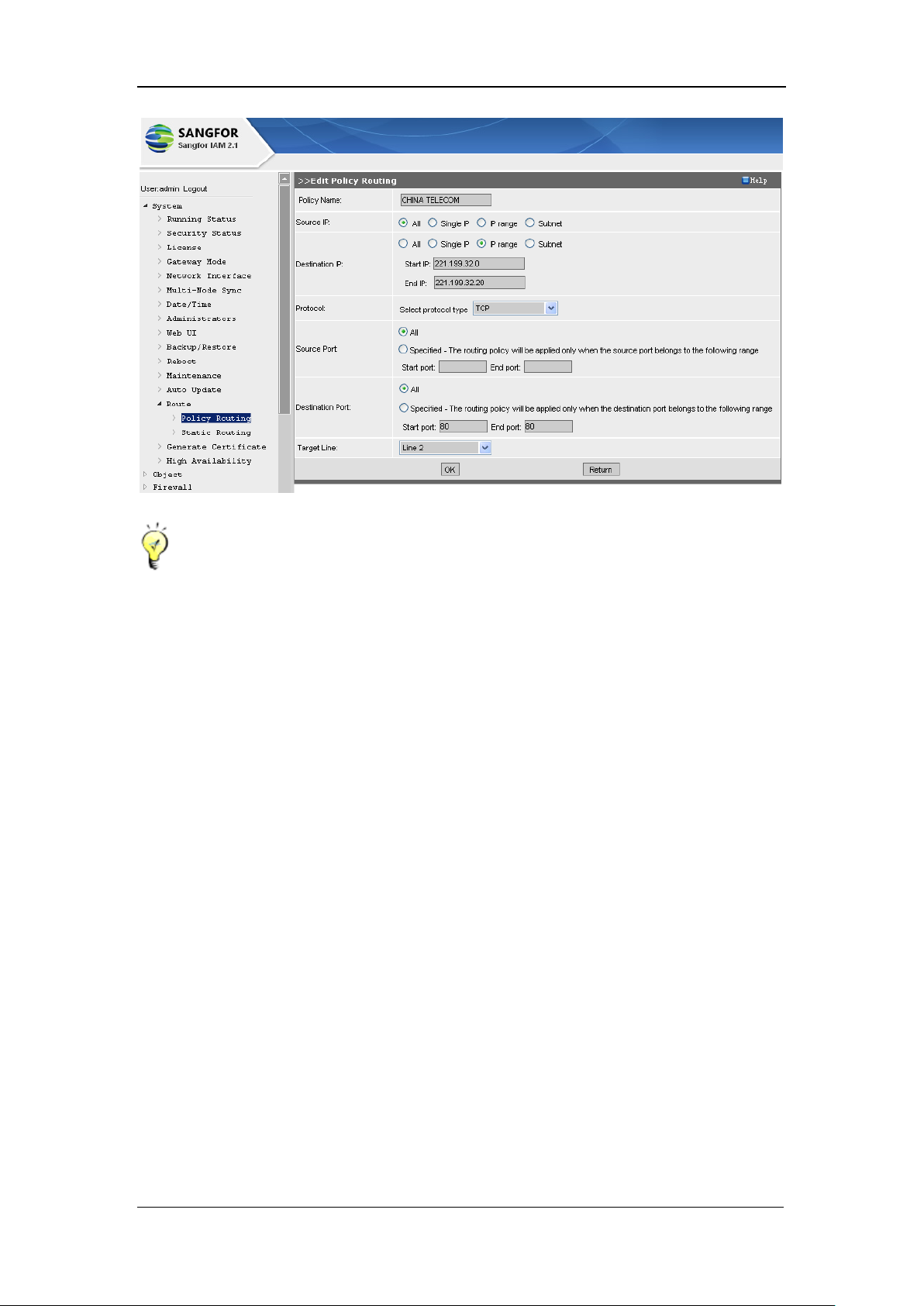
SANGFOR IAM v2.1 User Manual
50
If the selected [Target Line] is unavailable, IAM gateway device will arrange the data packets
with an available target line.
If you need the routing table of each ISP, please contact the Customer Service of SANGFOR.
Having gained the routing table, click the <Browse> button to upload the policy routing and
then click the <Import> button to import it.
3.14.2. Static Routing
SAGFOR IAM gateway device allows you to configure [Static Routing].
The configuration page is as shown below:
Page 52
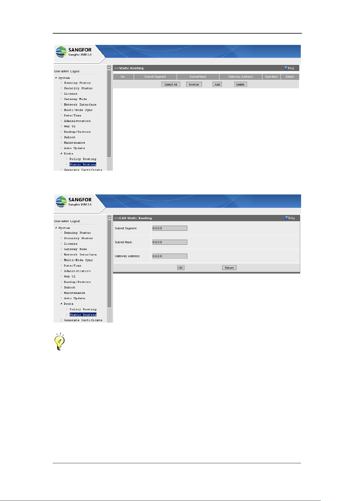
SANGFOR IAM v2.1 User Manual
51
Click the <Add> button and the [Edit Static Routing] configuration page appears:
[Static Routing] can enable the SNAT function (for multiple segments) to add return route.
Add return route for SNAT function (for multiple segments)
If there are several LAN segments access Internet through the SANGFOR gateway device,
then you need to add a [Static Routing], so that the IAM gateway device can return the data
packets of the LAN users (of different segments) to the LAN switch/route device properly.
Page 53
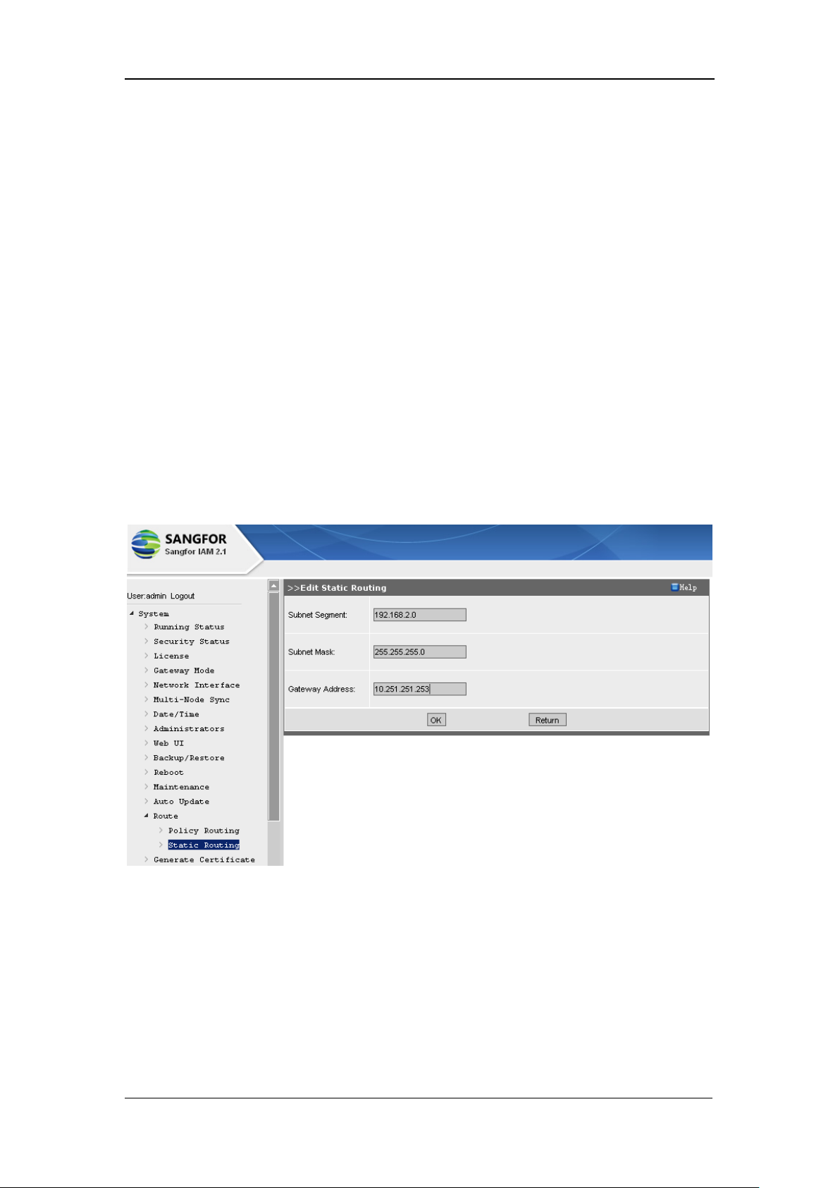
SANGFOR IAM v2.1 User Manual
52
Configuration Example of Static Routing
Provided that, there are two LAN segments, 10.251.251.X and 192.168.2.X, which are connected
to each other through a layer 3 switch. The LAN PCs of both the segments direct to the
corresponding gateway configured on the layer 3 switch. The LAN interface IP of the IAM
gateway device is 10.251.251.251 (of 10.251.251.X segment). The WAN interface connects to the
public network.
Requirement: Users of 10.251.251.X and 192.168.2.X segments get access to the Internet through
IAM gateway device, IAM gateway device acting as the egress.
Since 192.168.2.X and the LAN interface (10.251.251.251) of IAM gateway device are of
different segments, IAM gateway device has to add a static routing, the data packets from
192.168.2.X being forwarded to and handled by the LAN layer 3 switch (10.251.251.253) and
finally back to the PC(s) of 192.168.2.X segment. Specific steps and configurations are as shown
below:
Add the SNAT segments, namely, 10.251.251.0/24 and 192.168.2.0/24. For detailed steps, please
refer to Section 6.2.1 System Settings.
Add a static route in [Static Routing] page, the LAN IP addresses 192.168.2.0/24 directing to
gateway 10.251.251.253.
Page 54
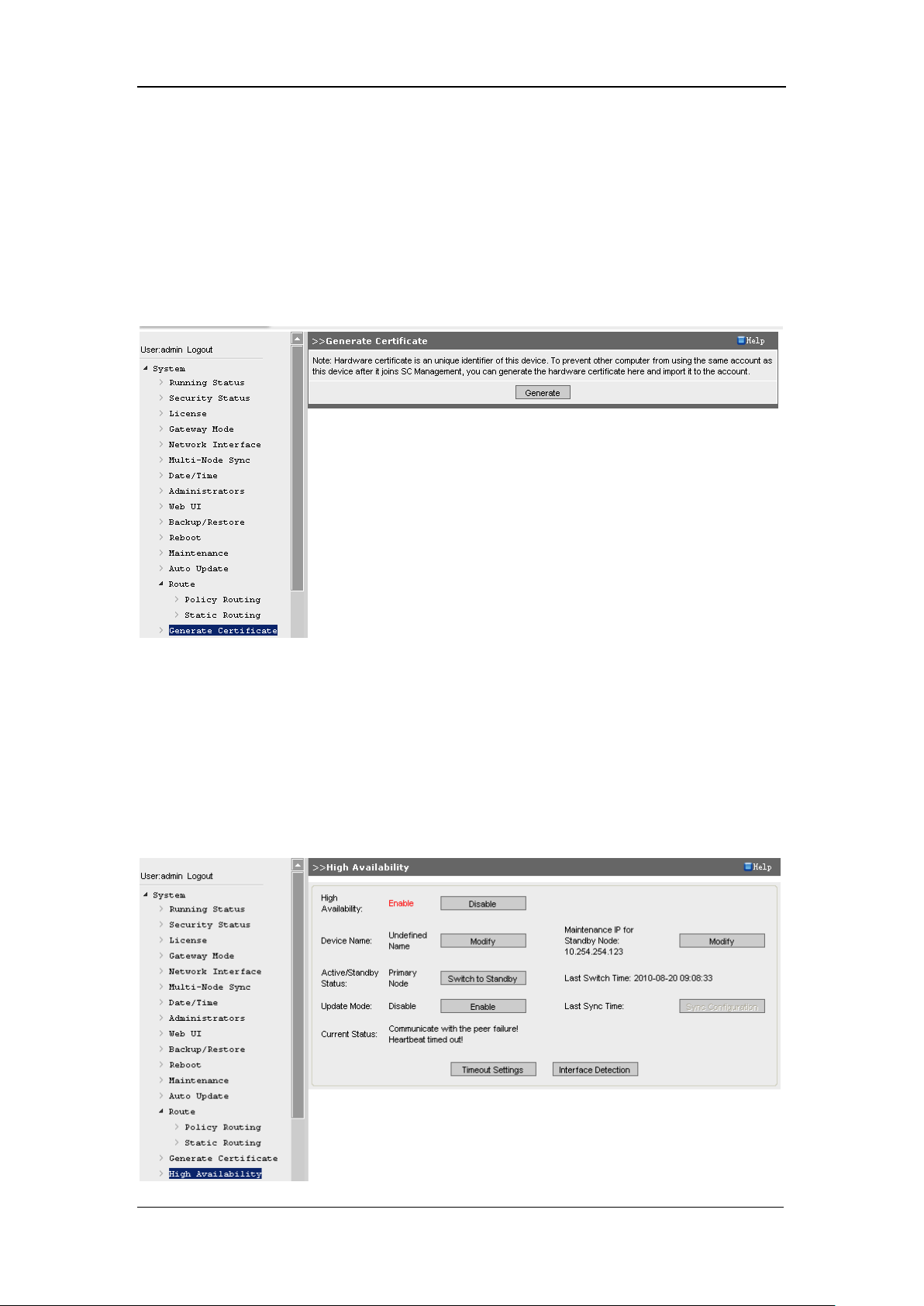
SANGFOR IAM v2.1 User Manual
53
3.15. Generate Certificate
[Generate Certificate]: Generates the hardware certificate which is the only label to distinguish
this device. This certificate can function as its ID when it registers on the SC (Secure Center)
Management.
The [Generate Certificate] page is as shown below:
3.16. High Availability
[High Availability] configured the mode of the redundant system (high availability). Setting
options are [High Availability], [Device Name], [Active/Standby Status], [Update Mode], [Current
Status].
The configuration page is as shown below:
Page 55
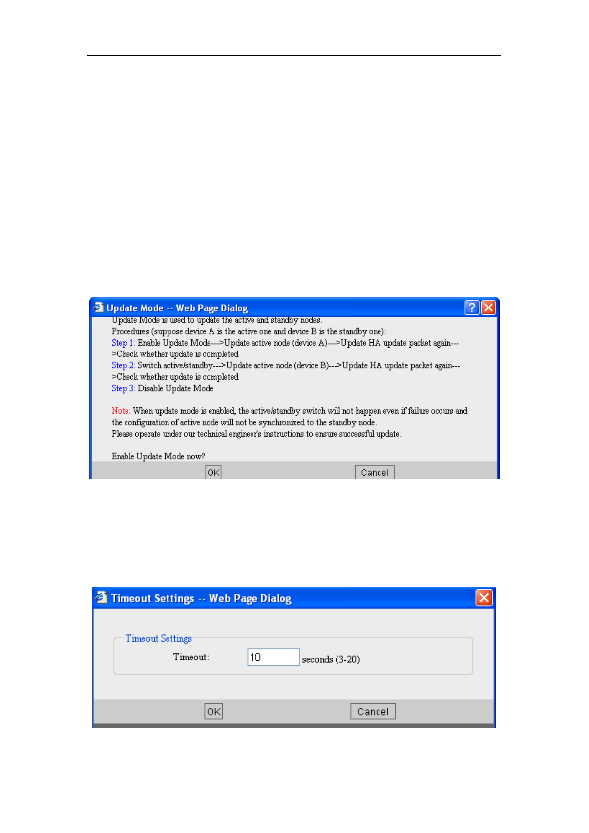
SANGFOR IAM v2.1 User Manual
54
[High Availability]: Displays the status of this function, enabled or disabled.
[Device Name]: Displays the name the local device. Click <Modify> to edit the device name.
[Active/Standby Status]: Displays the active or standby status of the local device. Click the
<Switch to Active> or the <Switch to Standby> button to switch the standby node to Active or
switch the active node to Standby.
[Update Mode]: Click this button to update the primary node, and lock the Active/Standby status.
Click [Enable] and the Active/Standby status cannot be altered, even though the primary node is
down. Please think it over to enable this function. It is recommended to enable [Update Mode]
when you are to update the primary and standby device; completing update, please disable
[Update Mode]. Click <Enable> and the following dialog pops up:
[Current Status]: Displays the communication status between primary and standby device, and the
timeout information as well. Timeout can be user-defined.
<Timeout Settings>: Click this button to enter the [Timeout Settings] page and define the
communication detection timeout, as shown in the following figure:
Page 56
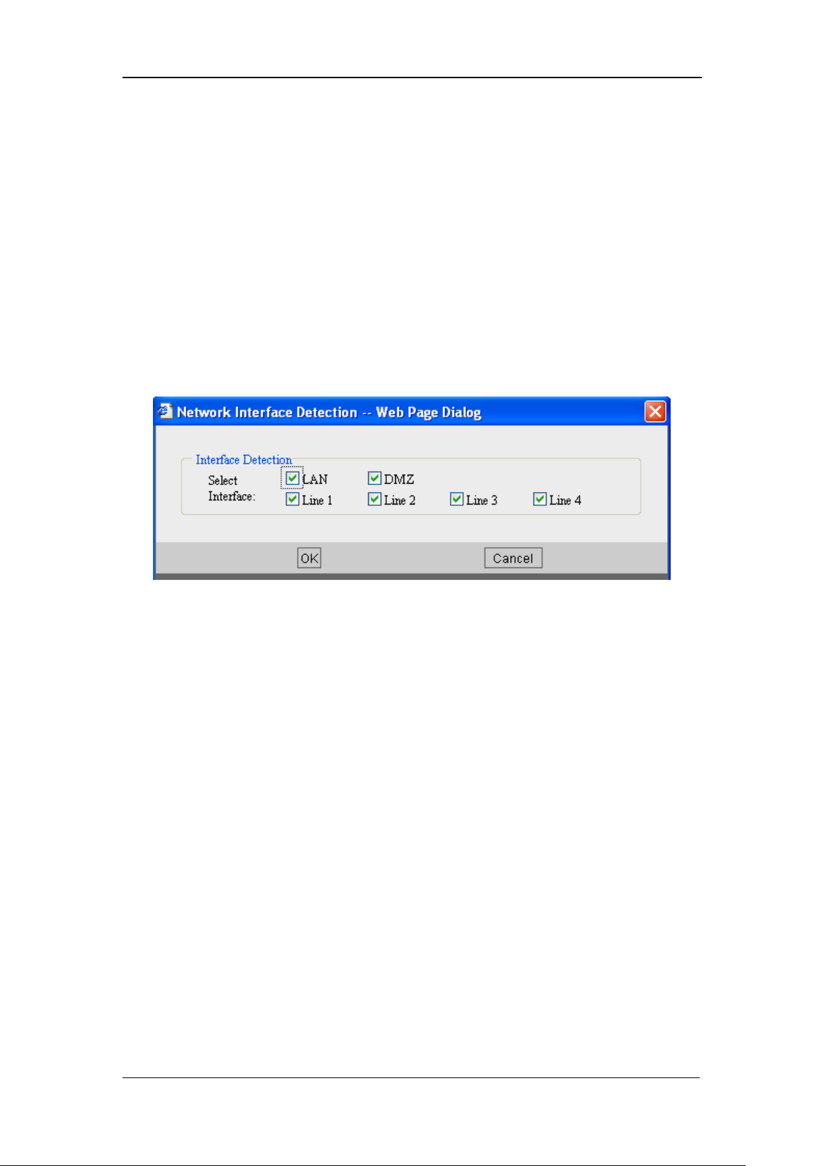
SANGFOR IAM v2.1 User Manual
55
Configuration Example of High Availability
Timeout of the primary node is 10 seconds, the primary node will send message to the standby
node every 10 seconds. If the standby node does not receive the message from the primary node in
10 seconds, the standby node will think the primary node got down and switch from Standby
status to Active status automatically.
Click the <Interface Detection> button to enter the [Network Interface Detection] dialog and
select the network interface(s) of the host to be detected. If any of the selected network interfaces
is down, the standby node switches to Active status. The interface can be any of the device
interfaces that connect to the public network. The configuration page is as shown below:
Page 57

SANGFOR IAM v2.1 User Manual
56
Chapter 4 Object
[Object] covers configuration of [Application Ident Rule], [Intelligent Ident Rule], [Server], [IP
Group], [Schedule], [URL Group], [White List Group], [Keyword Group], [File Type Group],
[Ingress Rule] and [SSL Certificate].
4.1. Application Ident Rule
Download software such as BT, emule, etc., consumes lots of bandwidth resource; IM software
such as QQ, MSN and stock trading software, etc., definitely occupies the office hours and lowers
down working efficiency. Though most of the enterprises issue regulations to ban their staff from
using these software tools, however, they can do nothing to prevent their staff from using them,
for nearly all of these software tools are designed to be able to shy away from the general
firewalls.
Application identification rule can detect traffic on the basis of protocol, port, direction, length of
data packet, and the content of the data packets, etc., which helps to identify P2P traffic quite well.
Application identification rule falls into internal rule and user-defined rule. The internal rules
cannot be modified, while the user-defined rule can be added, deleted, and edited, etc.
To obtain flow information of specific applications, you can choose the corresponding application
type or application, in association with the [Service Control] configuration in [IAM] > [Access
Control Policy] page > [Access Control], and [Bandwidth Settings] configuration in [Bandwidth
Management], to create a policy.
SANGFOR IAM gateway device adopts some patented technology to efficiently block the above
mentioned chat and IM software tools. Because the data packets of each kind of software have a
unique feature value, when the software communicates with the external networks, IAM gateway
device will detect the feature contained in the data packets and determines whether the data
packets should be blocked. If the data packets contain the features we configured, then it will not
be sent or received. In this way, this software will be unavailable for the LAN users.
Page 58
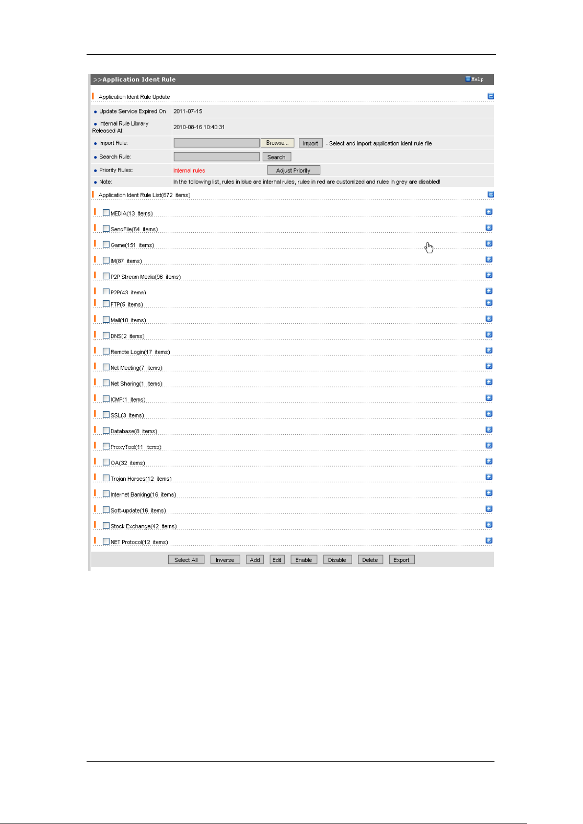
SANGFOR IAM v2.1 User Manual
57
The key to identify the application is to analyze the features of these data packets. SANGFOR will
periodically provide the feature values definition of the software such as P2P, IM, etc. You can
contact SANGFOR and apply for application identification rule packets to manually import the
rules, and you can analyze data packets by yourself and define your own application identification
rule by clicking the <Add> button. The pop-up [Edit Application Ident Rule] configuration page is
as shown below:
Page 59
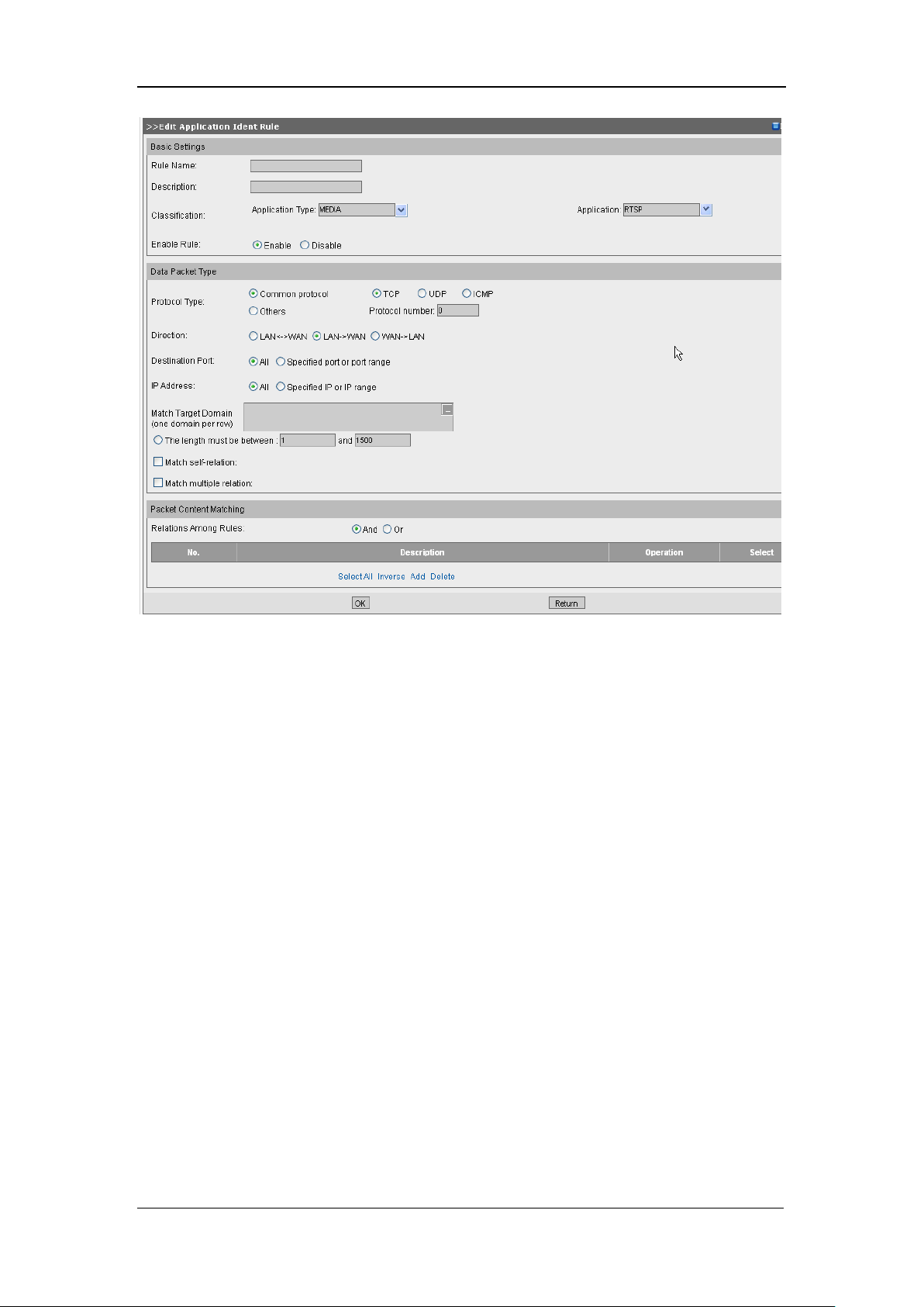
SANGFOR IAM v2.1 User Manual
58
Configure in [Packet Content Matching] section the feature value according to the analysis on the
data packets.
[Internal Rule Library Released At]: Indicates the latest time that the current version of internal
rule library was released at.
[Application Ident Rule] supports [Import] and [Export] of the rules. To export the existing
user-defined rule(s), just check the rule(s), click the <Export> button and name the file, and then
finally confirm to export (the internal rule cannot be exported).
[Import Rule]: To import a rule, click the <Browse> button and upload the rule (extension of the
rule file is *.ccf), then click the <Import> button.
[Search Rule]: Type in the keyword of a rule name, click the <Search> button and you can find the
rule whose name contains this keyword.
[Priority Rules]: Click the <Adjust Priority> button to switch the priority between the user-defined
application identification rules and the internal rules. The type of rules that has higher priority to
be matched is displayed in red.
Page 60
SANGFOR IAM v2.1 User Manual
59
Since BT and IM software differ from each other and keep updating, some application
identification rules may get invalid for some versions of the software. SANGFOR will
periodically update the application identification rules. Please make sure your IAM gateway
device can access the Internet.
For the internal rules, you can only alter the classification, but not edit the policy or export
the rule.
4.2. Intelligent Ident Rule
[Intelligent Ident Rule] mainly identifies the plain text or cipher text form P2P applications,
identifies the encrypted Skype data according to the Skype actions, and identifies the SSL
certificate, SANGFOR VPN data, data from proxy tool, and the VOIP and IM video and voice
data.
The configuration page is as shown below:
Page 61
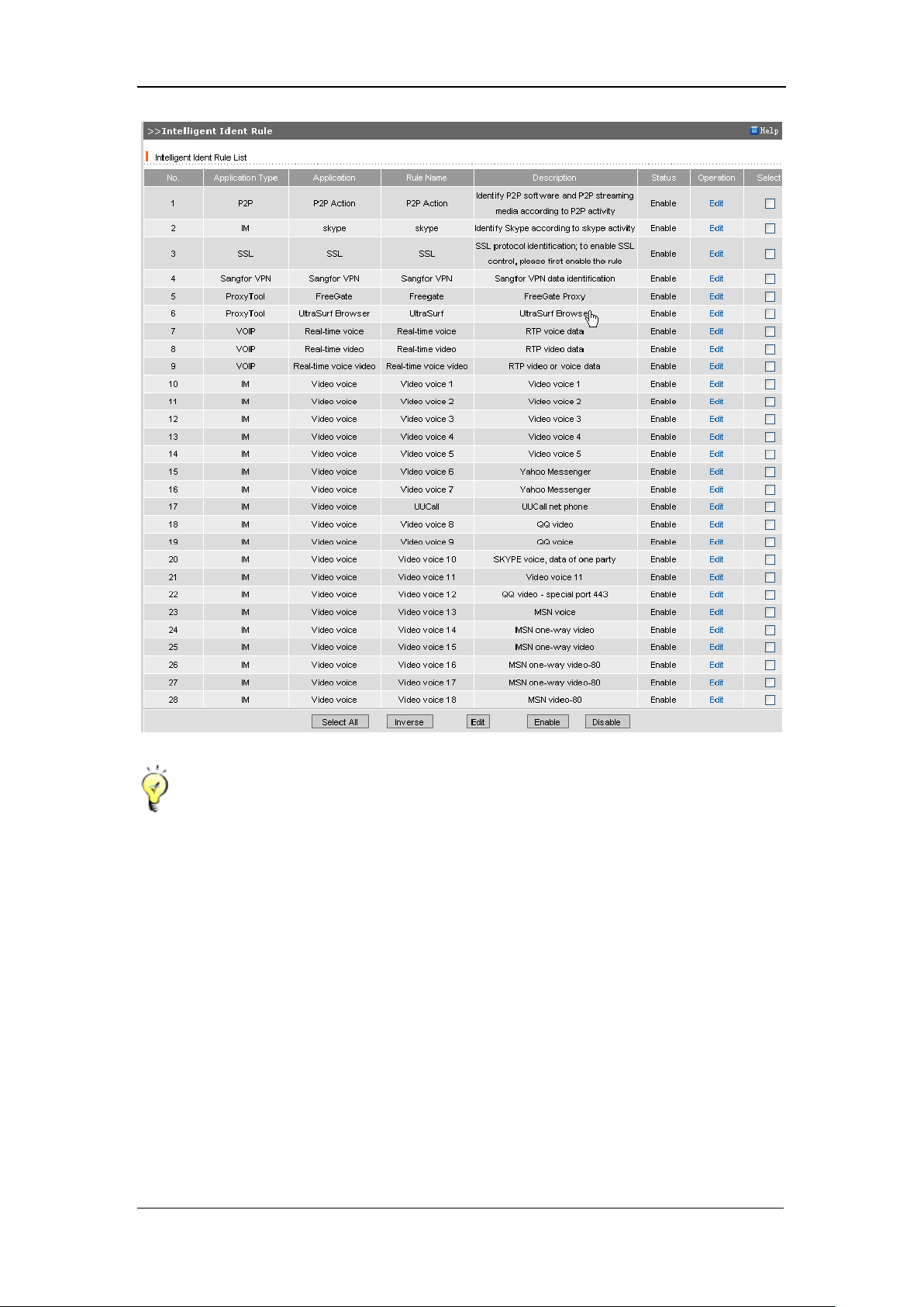
SANGFOR IAM v2.1 User Manual
60
[Application Ident Rule] detects the P2P application as well, limited to plaintext P2P data. If
you disable the [P2P Action] (in the Intelligent Ident Rule List on the [Intelligent Ident Rule]
page), it can still successfully identify the plaintext P2P data but fails to identify the cipher
text P2P data.
Skype data are encrypted. To control and record the Skype data, you have to configure it on
the [Edit Intelligent Ident Rule] page of [P2P Action], put in another way, you have to first
enable [P2P Action] (in the [Intelligent Ident Rule List] on the [Intelligent Ident Rule] page),
and then select the Skype application and enable the rule on the [Edit Intelligent Ident Rule]
page of [P2P Action].
As to control and record of video voice applications such as IM, VOIP, etc., you have to
configure and enable the [VOIP] rule in [Intelligent Ident Rule] > IM [Edit Intelligent Ident
Page 62
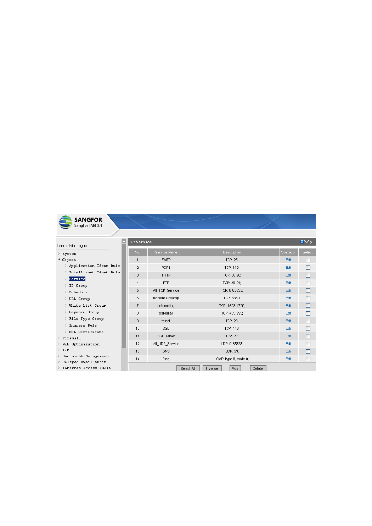
SANGFOR IAM v2.1 User Manual
61
Rule] and [Intelligent Ident Rule] > VOIP [Edit Intelligent Ident Rule].
4.3. Service
[Service] generally is in association with the rule configured in [Firewall] > [Firewall Rules] and
rules configured in [IAM] > [Access Control Policy] page > [Access Control] > [Service Control].
First, you need to define various services of the firewall in [Object] > [Service] including the port
and protocol applied; next, configure the filtering rules in [Firewall] > [Firewall Rules], referring
to the services defined previously, or configure access control in [IAM] > [Access Control Policy]
page > [Access Control] > [Service Control] according to the services defined previously.
The configuration is as shown below:
Click the <Add> button, and the [Edit Service] page pops up, as shown below:
Page 63
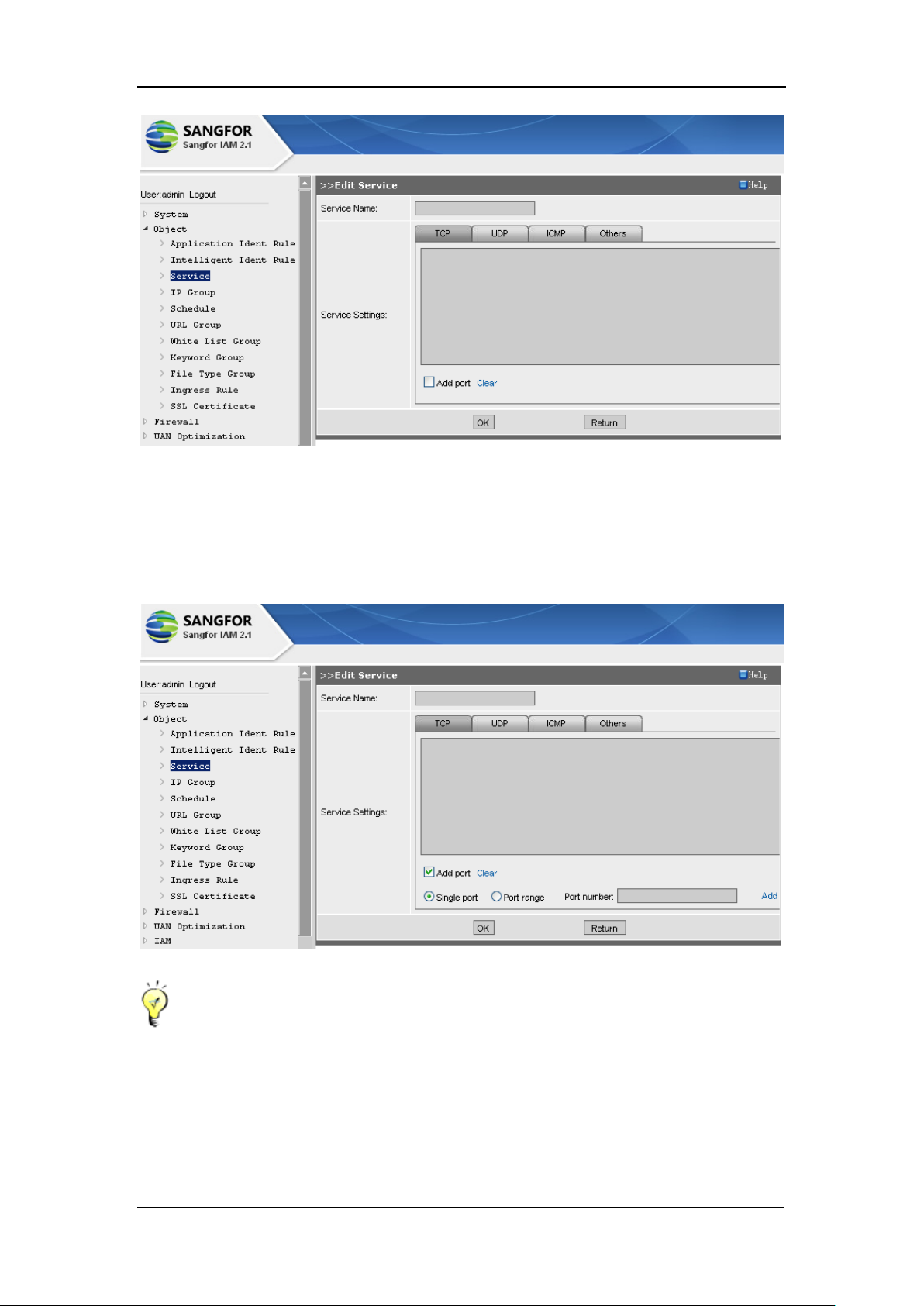
SANGFOR IAM v2.1 User Manual
62
[Service Name]: Type in a unique name for this new service (the characters better be easy for
memory) to distinguish it from others.
Click [TCP], [UDP], [ICMP] or [Others] to define the protocol to be applied; check [Add Port]
and type in a single port or a port range, as shown below:
If it is [Other] protocol, [Protocol number] 0 indicates all the protocols.
4.4. IP Group
An [IP Group] consists of some IP addresses which may be LAN IP range or WAN IP range or all
the IP addresses.
Page 64
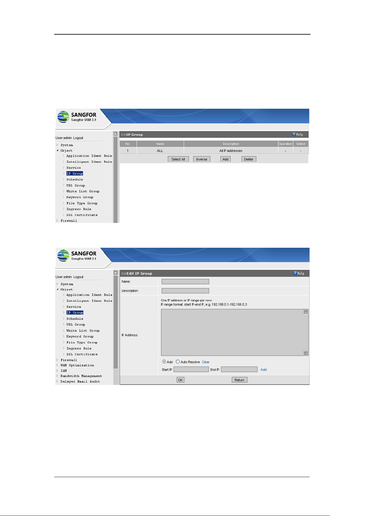
SANGFOR IAM v2.1 User Manual
63
[IP Group] generally is in association with the rule configured in [Firewall] > [Firewall Rules]. It
configures the source IP address, destination IP addresses, or defines the LAN users in association
with [IAM] > [Organization Structure] page > [Edit User] > [User Attribute] > [Binding] > [Bind
IP] > [Get from IP group], or defines the destination IP group in [IAM] > [Access Control Policy]
page > [Access Control] > [Service Control].
Click the <Add> button and the following [Edit IP Group] page pops up, as shown below:
[Name]: Names the newly-created IP group.
[Description]: Type in a brief description for this IP group.
[IP Address]: Defines the IP addresses contained by the IP group. Select [Add] and type in the
[Start IP] and [End IP] and then click the <Add> to add the IP address into the list; or select [Auto
Resole], type in the domain name and click <Resolve> to have the resolved IP addresses listed.
Page 65
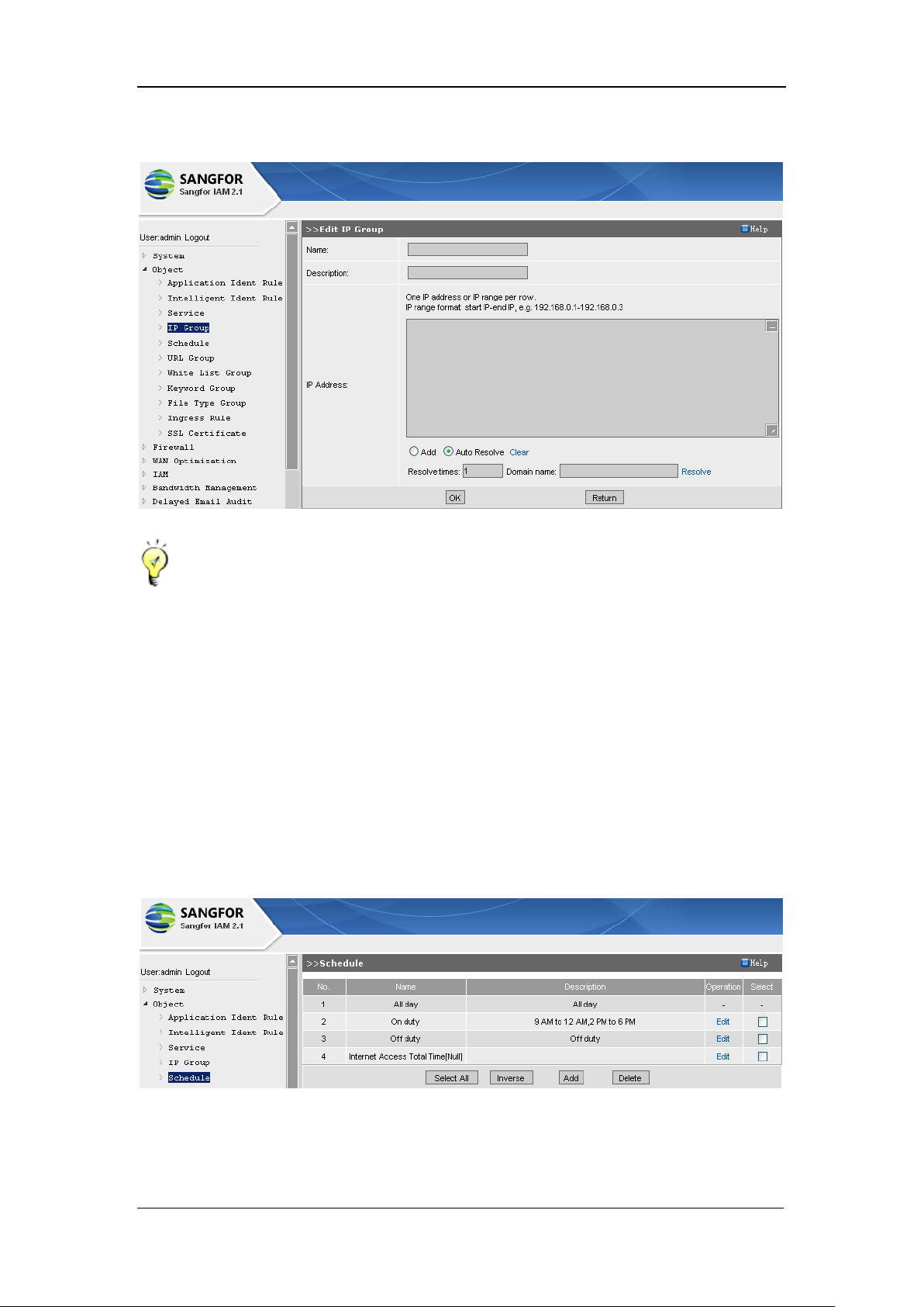
SANGFOR IAM v2.1 User Manual
64
Finally, you have to click the <OK> button to save all the settings.
The local PC can [Auto Resolve] the domain name, with the condition that the Internet is
accessible to it.
4.5. Schedule
[Schedule] defines the commonly used time periods, mainly used as valid time or expiry time. The
defined schedule can be referenced by [Firewall] > [Firewall Rules], and [IAM] > [Access Control
Policy] > [Access Control], and [Bandwidth Management] > [Bandwidth Settings] configuration
pages.
Click the <Add> button to enter the [Schedule] configuration page, as shown below:
Page 66
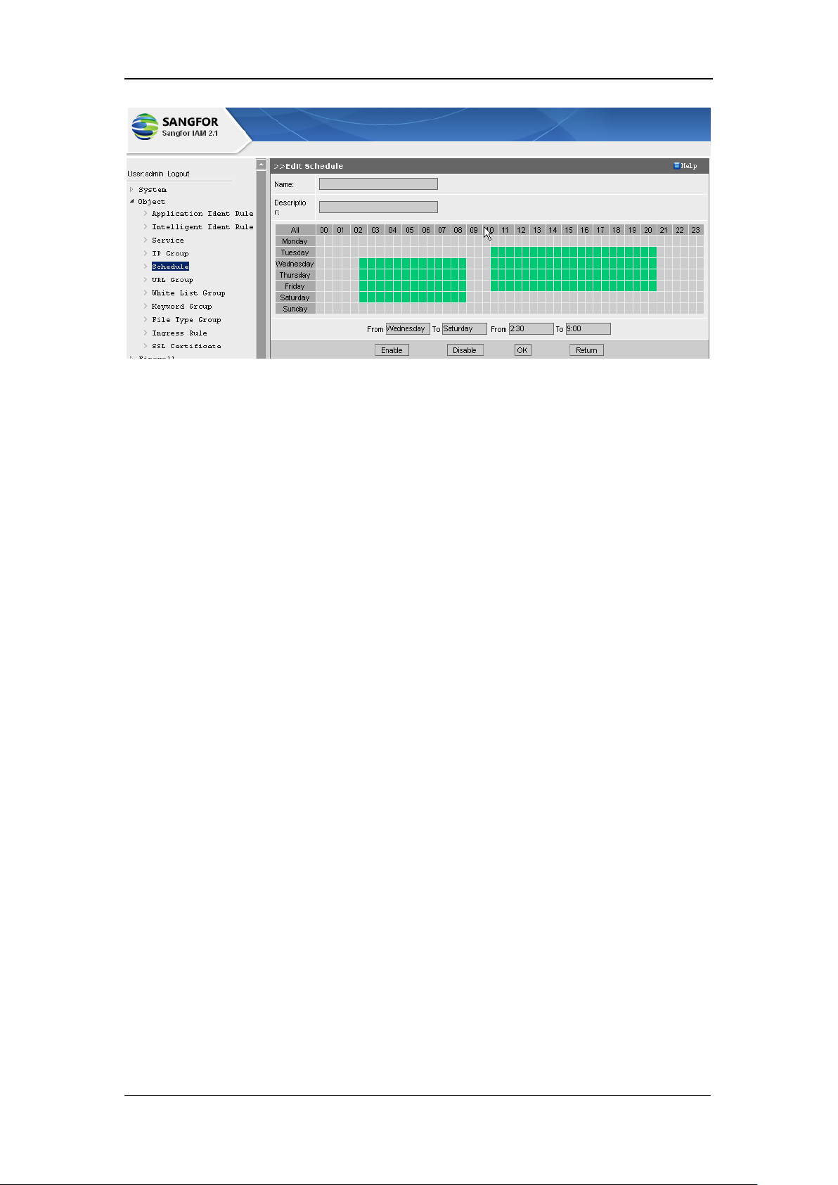
SANGFOR IAM v2.1 User Manual
65
[Name]: Names the newly-created schedule.
[Description]: Type in a brief description for this schedule.
Click (or click and drag) the needed time periods in the table and click the <Enable> button to
enable the selected time periods; and then click the <OK> button to save the settings on this page.
4.6. URL Group
[URL Group] is created according to the URL library, and can be referenced by [URL Filter]
configuration in [IAM] > [Access Control Policy] > [Web Filter] > [HTTP URL Filter] and
[HTTPS URL Filter], and by [Bandwidth Channel] configuration in [Bandwidth Management] >
[Bandwidth Settings] page, to achieve URL access filtering and bandwidth control.
Page 67
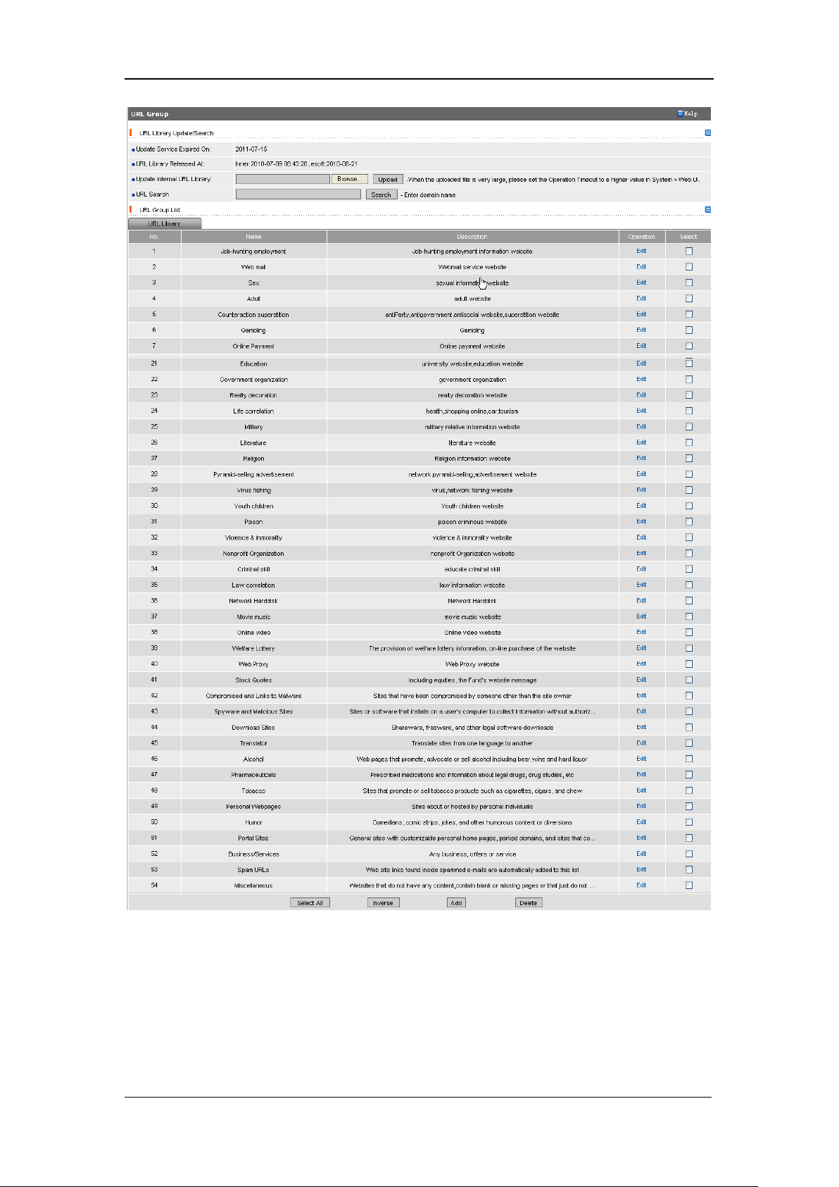
SANGFOR IAM v2.1 User Manual
66
[URL Library Released At]: Indicates the latest time that the current version of URL library was
released at.
[Update URL Library]: If the URL library cannot automatically update for it is disconnected to the
Internet, you can manually update the URL library. Just click the <Browse> button and upload the
URL library file from the local PC, and then click the <Upload> button.
Page 68
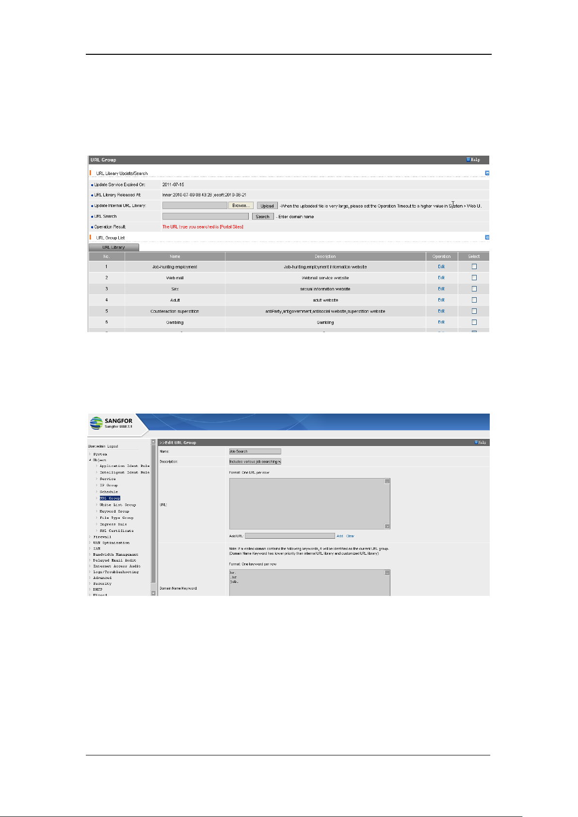
SANGFOR IAM v2.1 User Manual
67
[URL Search]: Enter the domain name into [URL Search] and click the <Search> button to search
whether this domain name exists in the URL library and in which URL group this domain name is
contained. For instance, type in www.sina.com and click the <Search> button, the search result is
displayed, as shown in the following figure:
IAM gateway device is built in with a large number of URL groups when it is delivered from the
factory. You can add a new URL into the URL library if necessary, in addition to using the existing
and built-in URLs.
[Name]: Name the new URL group.
[Description]: Type in a brief description for this new URL group
[URL]: Type the domain name (URL) into the text box. The URL group consists of the URL(s) in
this list. The wildcard character is supported.
[Add URL]: Type in a domain name (URL) into the [Add URL] text box and click the <Add>
button followed to add this domain name into the list, one entry (URL) per row.
Page 69
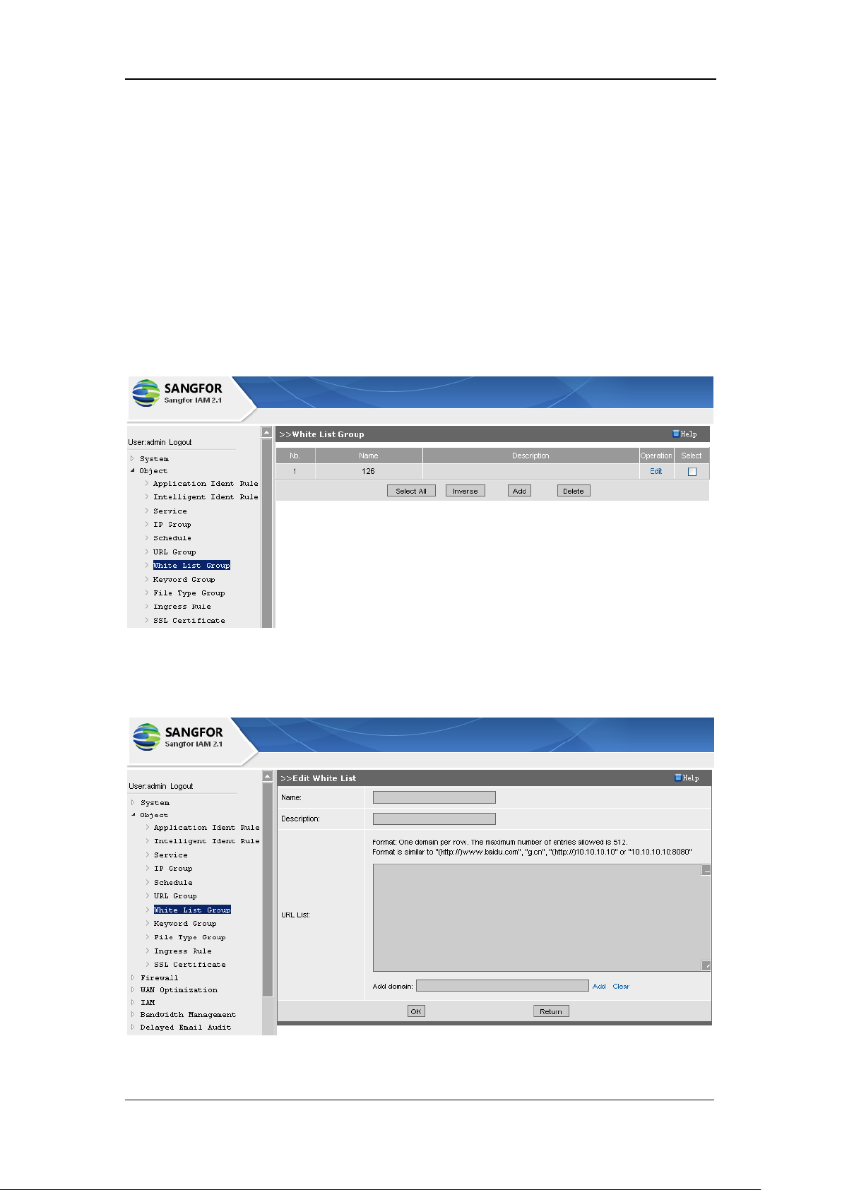
SANGFOR IAM v2.1 User Manual
68
[Domain Name Keyword]: URL group is automatically matched if the URL contains the
configured domain name keyword.
Having completed configuring this page, you have to click the <OK> button to save the settings.
4.7. White List Group
[White List Group] defines the domain name white list, which can be referenced by [Access
Control Policy] > [Edit Access Control Policy] > [Web Filter] > [File Type Filter], [ActiveX Filter]
and [Scrip Filter].
Under the default configuration page (above), click the <Add> button to enter the [Edit White List]
page, as shown below:
[Name]: Names the new white list group.
Page 70
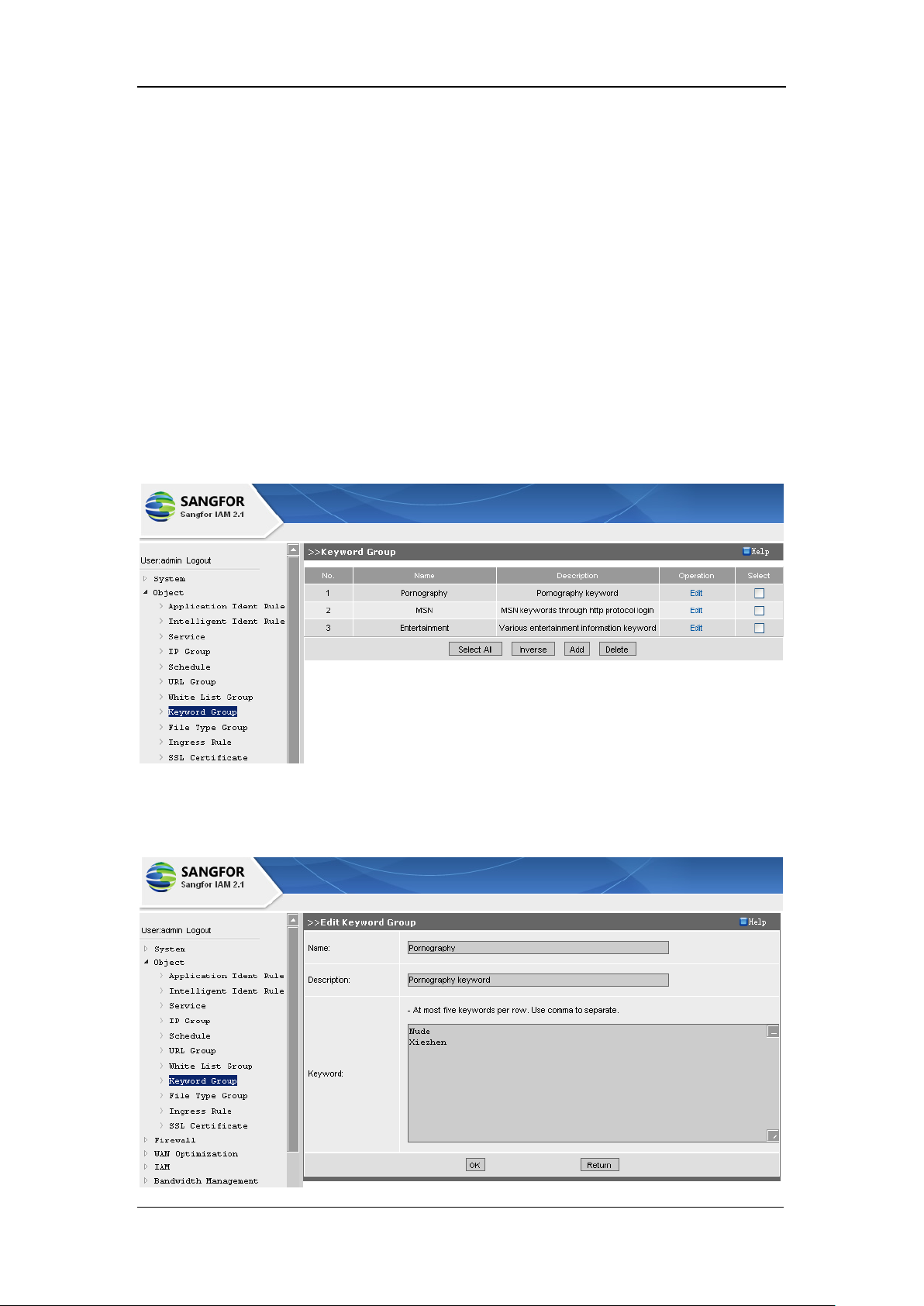
SANGFOR IAM v2.1 User Manual
69
[Description]: Type in a brief description for this white list group.
[URL List]: Configures the composition of the white list group, one domain name (IP address) per
row.
Having completed configuring, you have to click the <OK> button to save the settings.
4.8. Keyword Group
[Keyword Group] is used for configuring and classifying the keywords. The [Keyword Groups]
can be referenced by [IAM] > [Access Control Policy] > [Edit Access Control Policy] page >
[Web Filter] > [Keyword Filter] to control searching and uploading information that contains the
keywords in the keyword group.
Under the [Keyword Group] default configuration page, click the <Add> button to enter the [Edit
Keyword Group] page, as shown below:
Page 71
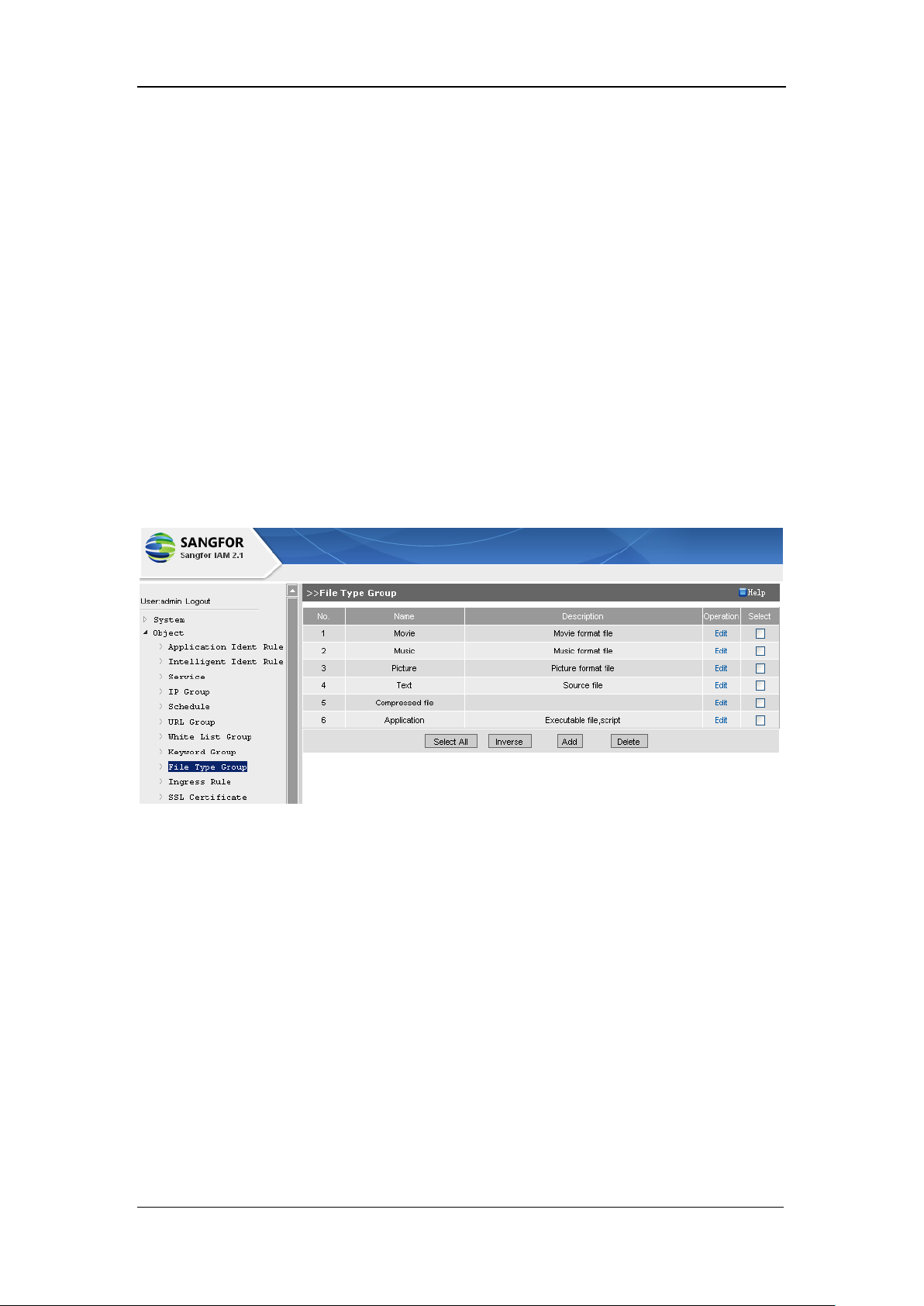
SANGFOR IAM v2.1 User Manual
70
[Name]: Names the new keyword group.
[Description]: Type in a brief description for this keyword group.
[Keyword]: Configures the keywords, one entry (keyword) per row.
Having completed configuring, you have to click the <OK> button to save the settings.
4.9. File Type Group
[File Type Group] defines the needed file types. [File Type Group] can be referenced by [IAM] >
[Access Control Policy] > [Edit Access Control Policy] page > [Web Filter] > [File Type Filter] to
control HTTP and FTP upload and download, and can be referenced by [Bandwidth
Management] > [Bandwidth Settings] page > [Bandwidth Channel] to control the upload and
download bandwidth of the configured file types (in the file type group).
Under the default configuration page, click the <Add> button to enter the [Edit File Type Group]
default configuration page, as shown below:
Page 72
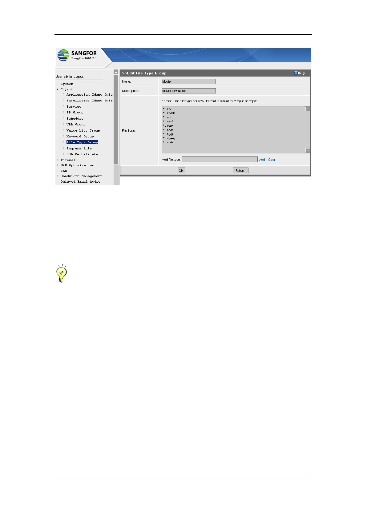
SANGFOR IAM v2.1 User Manual
71
[Name]: Names the new file type group.
[Description]: Type in a brief description for this file type group.
[File Type]: Configures the extension of file type, one entry per row.
Having completed configuring, you have to click the <OK> button to save the settings.
Extension name of a file type cannot be entered twice or more.
4.10. Ingress Rule
[Ingress Rule] configures the rules to be applied when users get access to the Internet. The ingress
rules are to ban the use of proxy software, bind IP/MAC address of three layers and monitor
encrypted IM message, and can be referenced by [IAM] > [Access Control Policy] > [Edit Access
Control Policy] page > [Ingress Rule]. If the access control policy has referenced ingress rule(s),
users have to satisfy the corresponding rules to access the Internet, and install the ActiveX control
when getting access to the Internet for the first time.
IAM gateway device is built in with some ingress rules; you can define ingress rule(s) by yourself.
Page 73
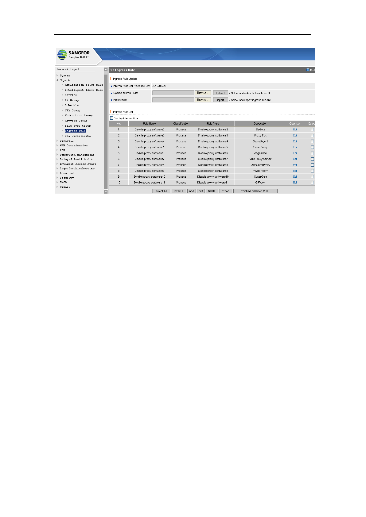
SANGFOR IAM v2.1 User Manual
72
[Update Internal Rule]: Click the <Browse> button to upload the internal ingress rule file and
update the current internal rules. You can obtain this file from SANGFOR Customer Service.
[Import Rule] is corresponding to the <Export> button below the [Ingress Rule List] which can
export the selected ingress rule file(s) of .conf format; while the <Import> button is used for
importing the uploaded .conf format rule file into the system.
<Combine Selected Rules>: Select two or more ingress rules and click this button to combine the
selected rules, as shown below:
Page 74
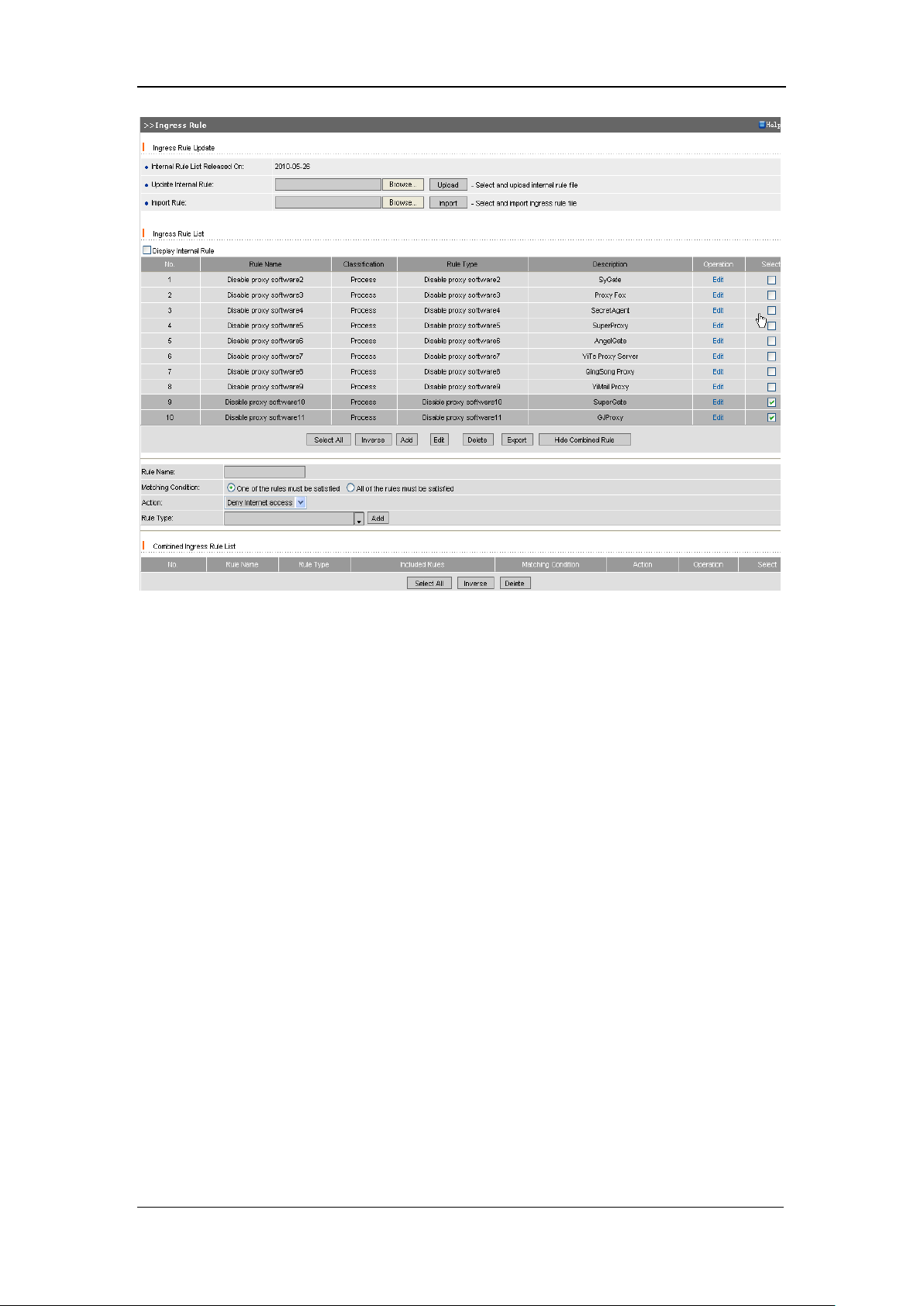
SANGFOR IAM v2.1 User Manual
73
[Rule Name]: Names the combined ingress rule.
[Matching Condition]: Select the matching condition to the combined rule, [One of the rules must
be satisfied] or [All of the rules must be satisfied].
[Matching Condition]: Defined the relations between the combined rules. Options are [One of the
rules must be satisfied] and [All of the rules must be satisfied].
[Action]: Select the action if the [Matching Condition] is satisfied. Options are [Deny Internet
access] and [Submit report only].
[Rule Type]: Defines the type of this combined rule.
Having completed configuring the above, you have to click the <Add> button to add this
combined rule to the [Combined Ingress Rule List].
To create a new ingress rule, click the <Add> button (below the [Ingress Rule List]) to enter the
[Edit Ingress Rule] configuration page, as shown below:
Page 75
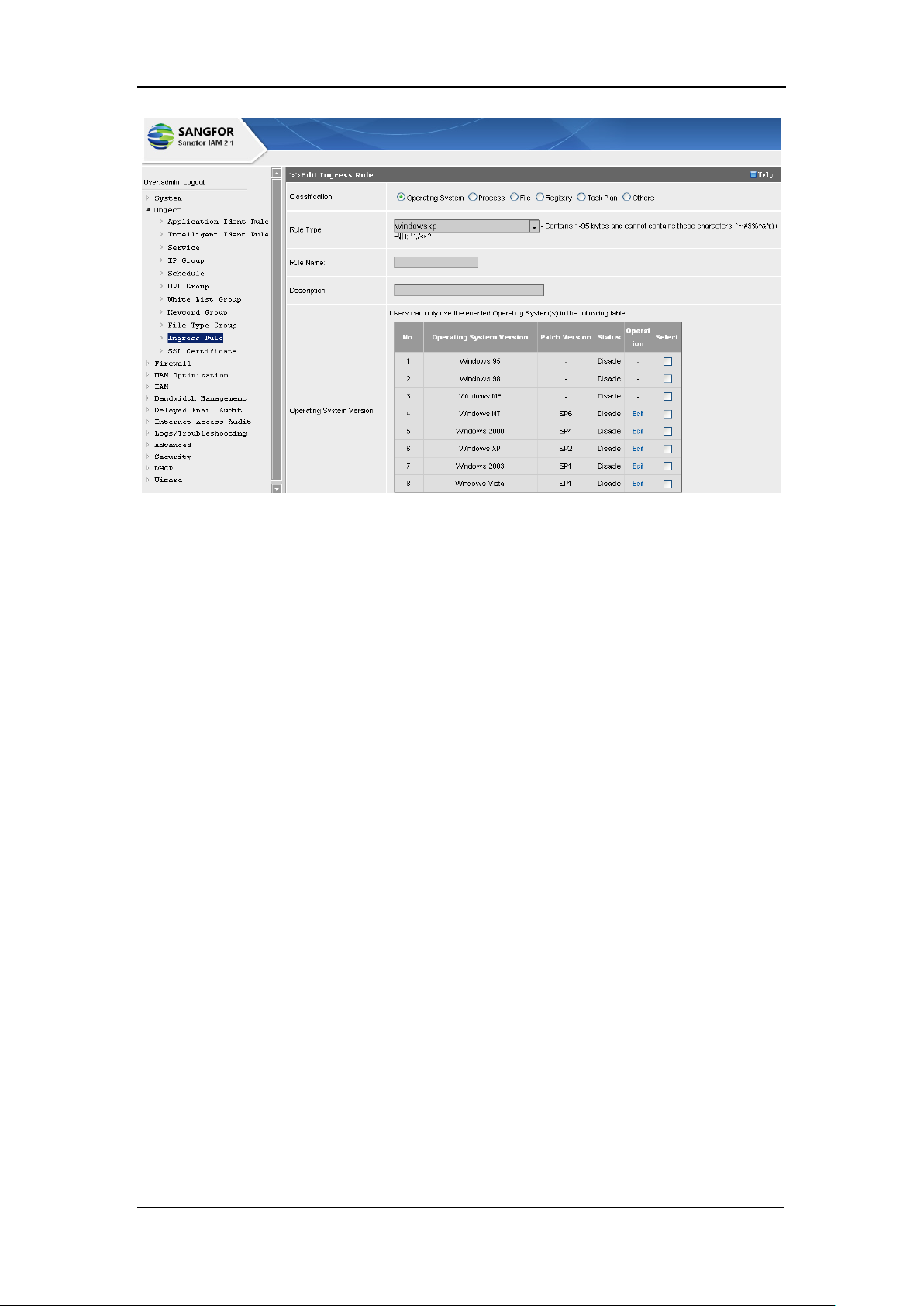
SANGFOR IAM v2.1 User Manual
74
[Classification]: Defines the classification of this ingress rule; options are [Operation System],
[Process], [File], [Registry], [Task Plan] and [Others].
[Rule Type]: Select the type for this ingress rule (or enter directly a new user-defined rule type
name into the text box followed).
[Operating System] ingress rule specifies the operating system of the LAN computer which is
going to get access to the Internet through the IAM gateway device. For instance, if the LAN
computers of an enterprise use the Microsoft Windows XP, in order to prevent the LAN users from
infecting virus who do not download the SP2 patch, we take the following measures: IAM
gateway device monitors all the Internet access data packets from the LAN PCs, the PCs that have
downloaded the SP2 patch can get access, while the PCs that have not downloaded the SP2 patch
cannot access the Internet. Detailed configuring procedures are as shown below:
Page 76
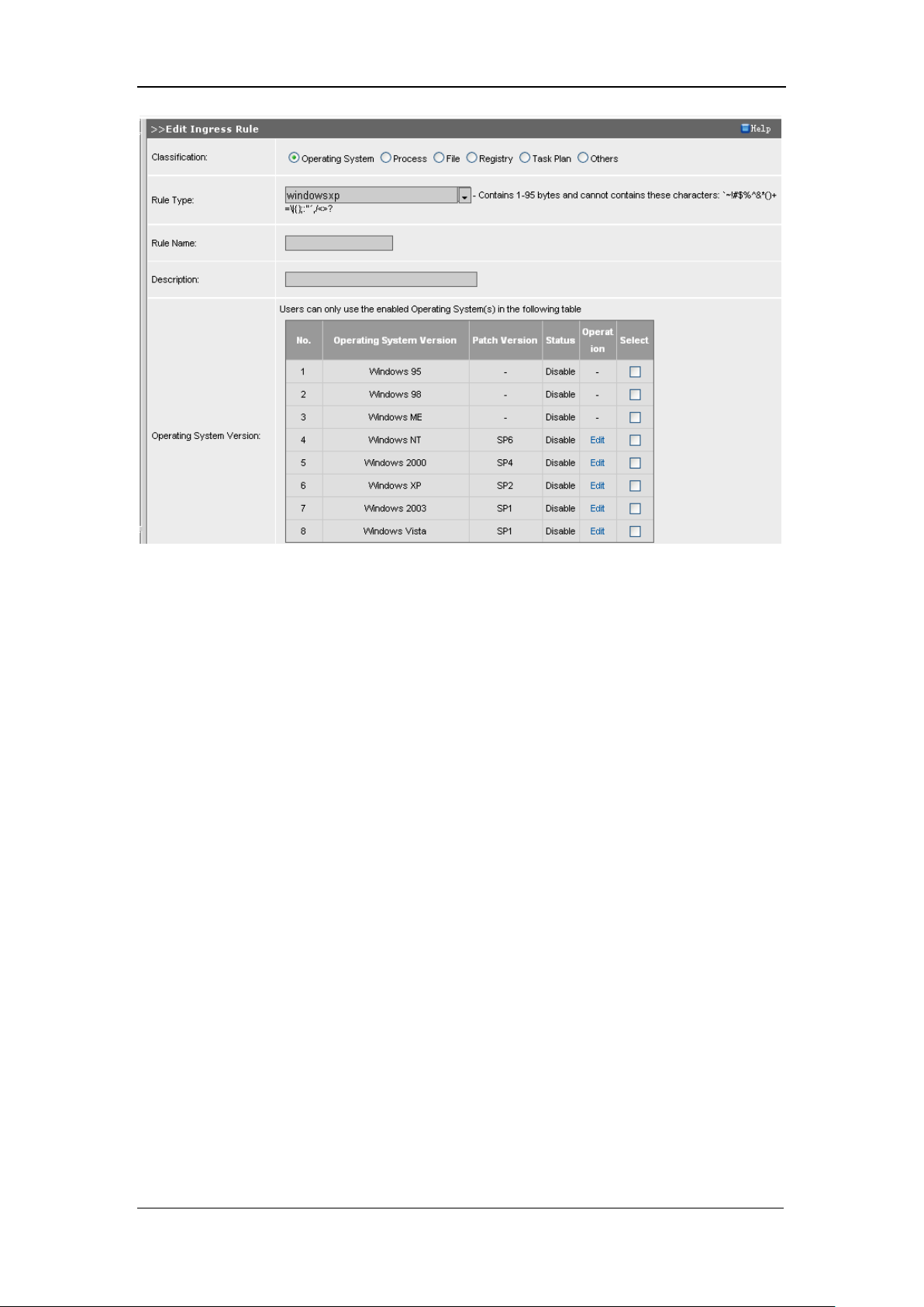
SANGFOR IAM v2.1 User Manual
75
Step 1: <Add> a new ingress rule. Select [Classification] (or any other existing rule type).
Step 2: Enter [Rule type]. Click the pull-down menu and select a rule type, or enter a new one.
Length of rule type must be within 95 bytes.
Step 3: Enter [Rule Name]. Length of a rule name must be within 95 bytes.
Step 4: Select [Operating System Version]. If no operating system version is selected, this ingress
rule will ban the user from accessing Internet. First, select operation version(s) and then click
<Enable> to enable this OS version.
Step 5: Select [Action], to [Deny Internet access] or [Submit report only].
Step 6: Click the <OK> button to enable this ingress rule.
[Process] ingress rule controls the process on the LAN computers that are getting access to the
Internet. Click the <Add> button and create a new ingress rule of [Process], the page is as shown
below:
Page 77
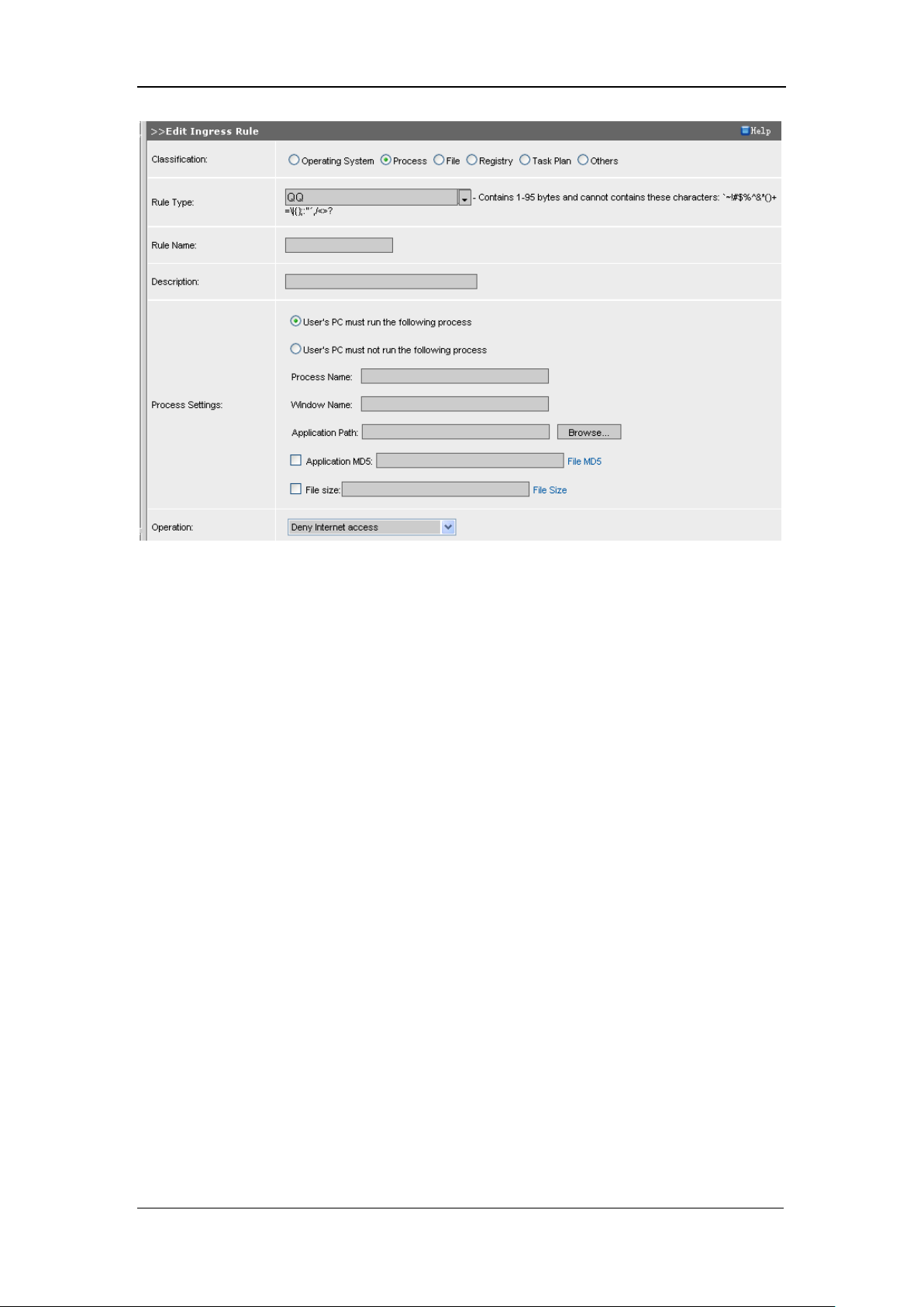
SANGFOR IAM v2.1 User Manual
76
Configure [Rule Type], [Rule Name], [Description], [Process Settings] (including [Process Name],
[Window Name], [Application Path], [Application MD5], [File Size], etc.), and [Operation] as
[Deny Internet access], [Stop Process] or [Submit report only]
Having completed configuring this page, click the <OK> button to save the settings and add this
ingress rule to the [Ingress Rule List].
[File] ingress rule controls the files of the LAN computers who get access to the Internet through
the IAM gateway device. If you enabled this type of ingress rule, the IAM gateway will detect
whether there is certain file (for instance .dll file) and therefore check whether the LAN computer
has installed the specific software.
Configuration page of [File] ingress rule is as shown below:
Page 78
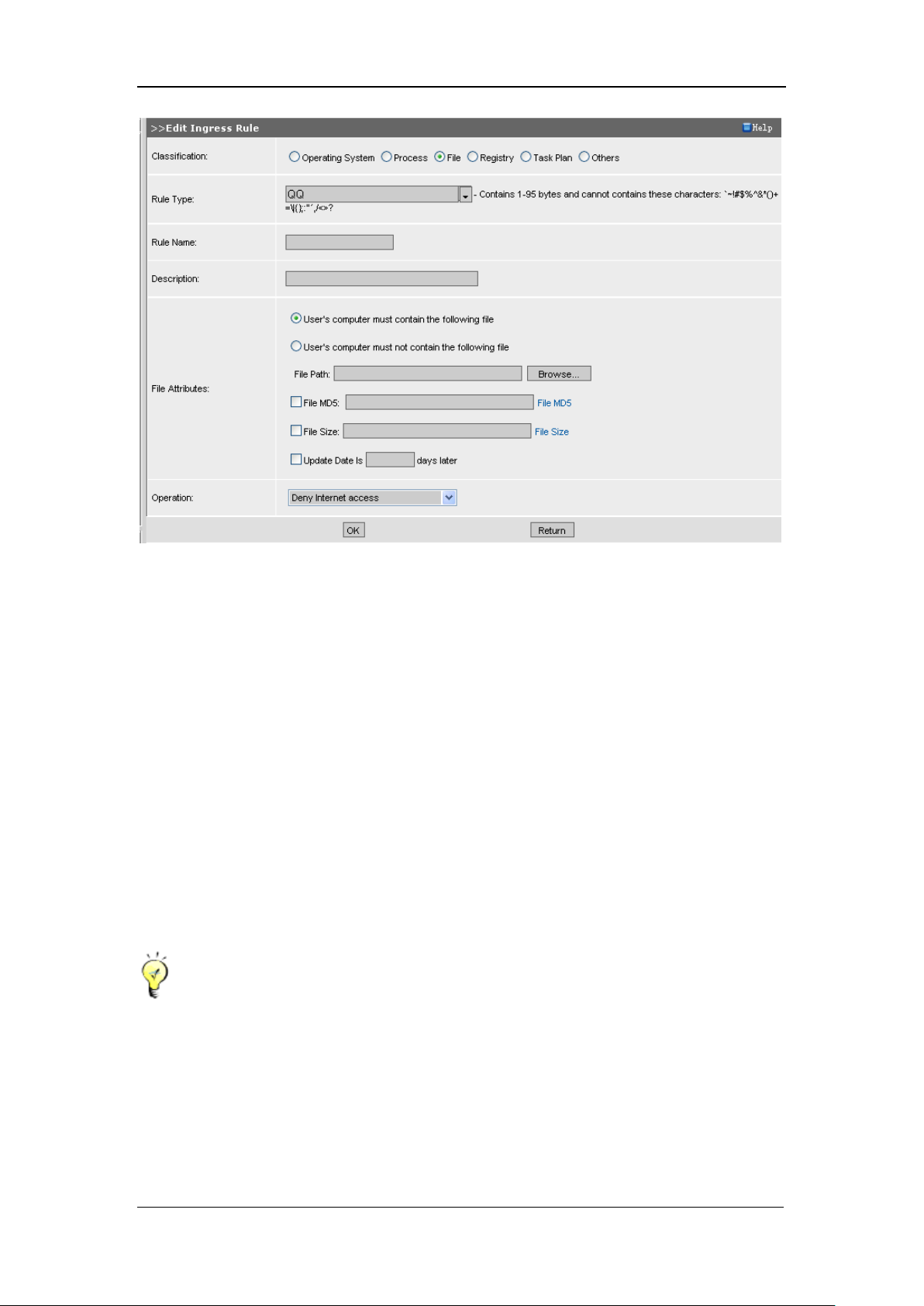
SANGFOR IAM v2.1 User Manual
77
Configure [Rule Type], [Rule Name], [Description]
[File Attributes]: Options are [User‟s computer must contain the following file] and [User‟s
computer must not contain the following file]; enter the file path or click <Browse> to upload the
file; check and calculate the [File MD5], [File Size] and [Update Date is _ days later]. Select an
[Operation].
[Update Date is _ days later]: Indicates whether the antivirus software of the LAN computer is
updated or not, and for how many days the antivirus software on the LAN computer has lagged
behind to be updated. If the time is longer than the days configured here, the IAM gateway device
will take the corresponding operation.
Having completed configuring this page, click the <OK> button to save the settings and add this
rule to the [Ingress Rule List]
[File Path] can be translated, for instance, %SystemRoot% indicates where the Windows
system directory is (provided the C disk is the system disk), generally C:\WINDOWS or
C:\WINNT. Since the software files are installed in different subdirectories, macro directory
translation makes sense.
If you are adding a [File] ingress rule, yon can use the macro directory translation function to
Page 79
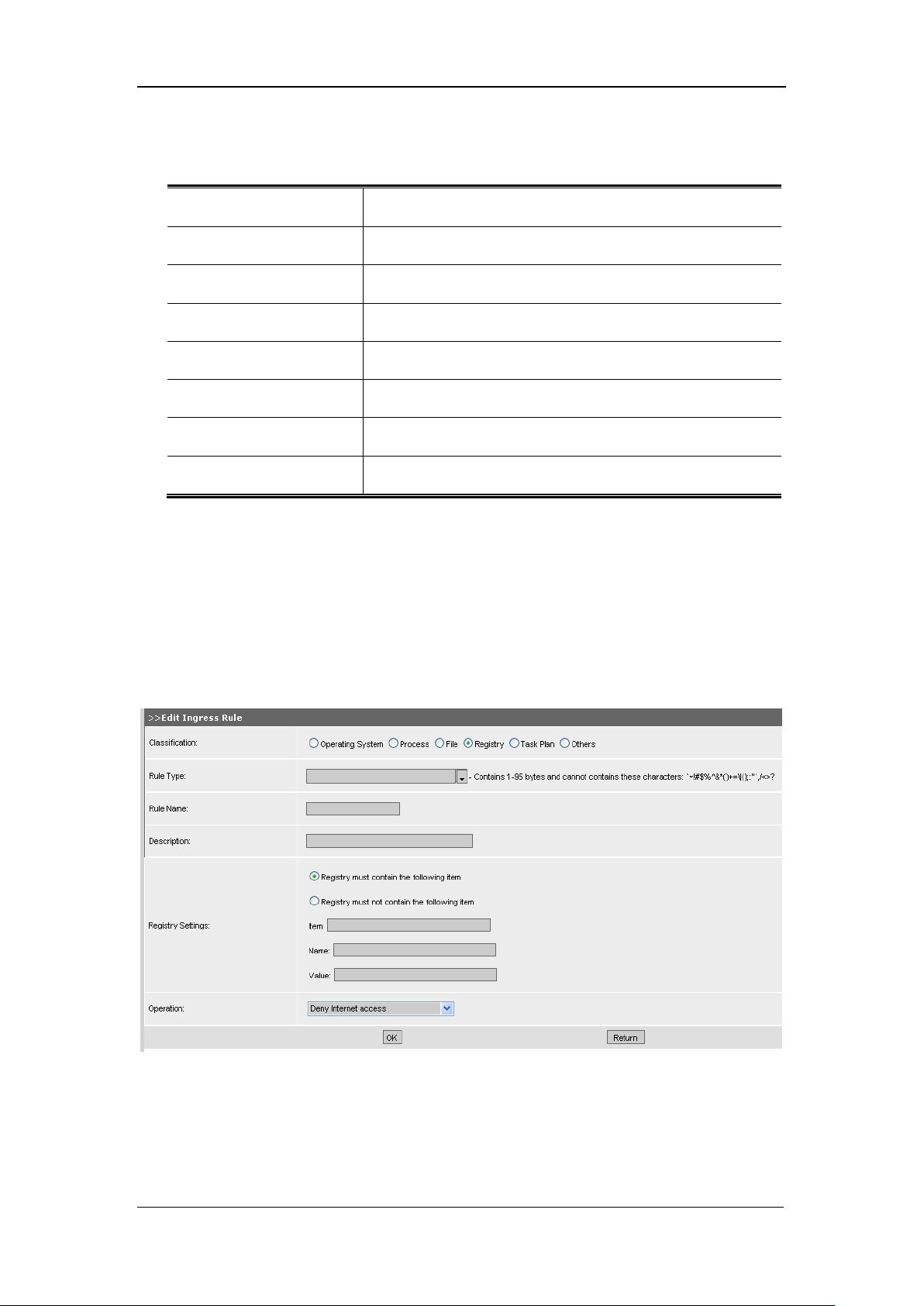
SANGFOR IAM v2.1 User Manual
78
Format
Definition (provided the C disk is the system disk)
%SystemDrive%
C:
%SystemRoot%
C:\WINNT
%System%
C:\WINNT\system32
%Windir%
C:\WINNT
%UserProfile%
C:\Documents and Settings\SINFOR
%Temp%
C:\Documents and Settings\SINFOR\Local Settings\Temp
%Program%
C:\Program Files
type the [File Path] that is provided by IAM gateway device. Definitions of some the macro
directories are as shown in the following table (case insensitive):
[Registry] ingress rule checks the Registry of the operating system of the LAN computer that gets
access to the Internet through the IAM gateway device. In this way, it can find the software and
security problems of the software of the operating system.
The configuration page of the [Registry] ingress rule is as shown below:
[Task Plan] ingress rule configures the script and program that the client terminal may run (the
script and program is user-defined); the IAM gateway device then can control the Internet access
Page 80
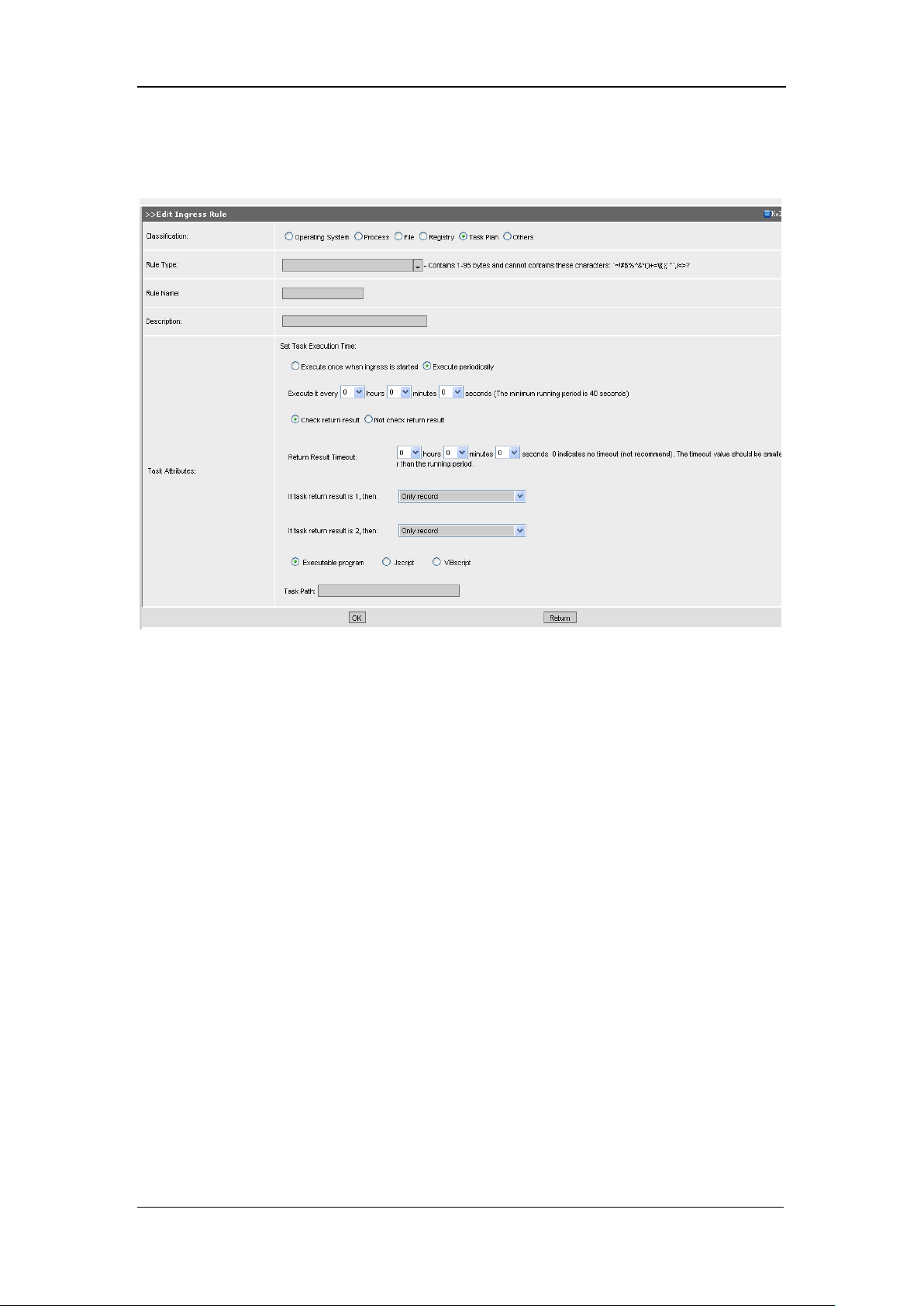
SANGFOR IAM v2.1 User Manual
79
with the return value.
The [Task Plan] ingress rule configuration page is as shown below:
[Rule Type]: Configures the type of the ingress rule.
[Rule Name], [Description]: Configures the name and brief description for the ingress rule.
[Task Attributes]: Configures the task execution time, [Execute once when ingress is started] or
[Execute periodically].
If the [Execute periodically] is selected, you can configure the interval for periodic execution, as
shown in the figure above.
[Check return result], [Not check return result]: Configures whether to check the execution results
of the task script.
[Return Result Timeout]: Configures the timeout for obtaining the return results.
[If task return result is 1, then], [If task return result is 2, then]: Configures the operation taken if
the obtained task script is incoherent to the return results. It may [Only record], or [Prompt user],
or [Deny Internet Access], or [Deny Internet access/prompt user]. Presently, only some of the
scripts are supported, namely, [Executable program], [Jscript] and [VBscript].
[Task Path]: Type in the detailed path where the task script is saved in the local client-end PC.
Page 81
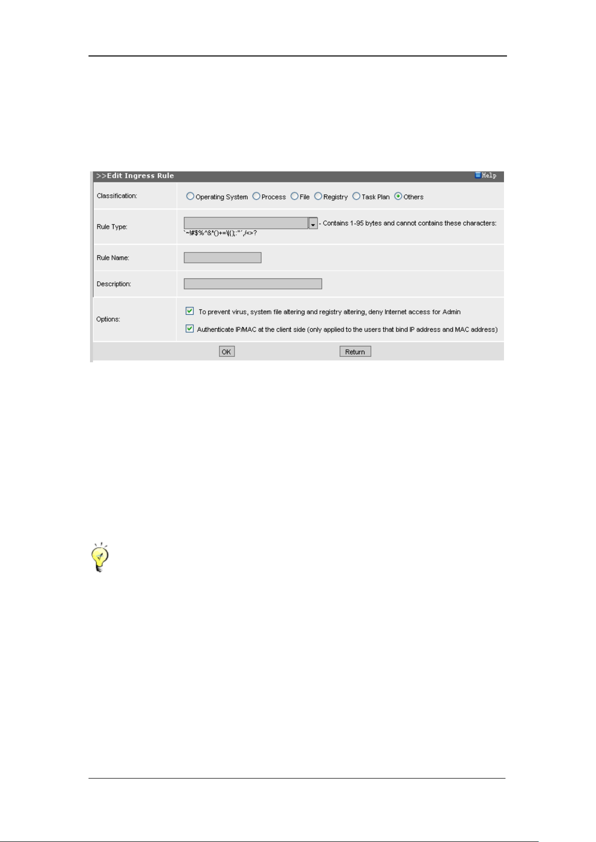
SANGFOR IAM v2.1 User Manual
80
[Others] ingress rule can fulfill IP/MAC binding over the layer 3 switch, and ban the client end
from logging into a LAN PC as administrator to access the Internet, which can avoid virus
infection.
The [Others] ingress rule configuration page is as shown below:
Configure [Rule Type], [Rule Name], [Description], etc.
[Options]: Check [Authenticate IP/MAC at the client side] to realize IP/MAC binding over the
layer 3 switch; check [To prevent virus, system file altering and registry altering, deny Internet
access for Admin] to ban the client end from logging in to a LAN PC as administrator to get
access to the Internet.
Having completed configuring this page, you have to click the <OK> button to save the settings
and add the ingress rule to the [Ingress Rule List].
The condition for applying ingress rule to bind IP/MAC is that, the PC and the IAM
gateway device must be at different subnet segments (crossing a layer 3 switch and the MAC
address changed). In addition to the settings configured here, IP/MAC binding must be configured
in [IAM] > [Organization Structure] > [Edit User] page > [Advanced Settings] > [User Attribute].
For details, please refer to Section 7.4.5.1 Edit User.
4.11. SSL Certificate
[Trusted Root Certificate List] is coherent to [IAM] > [Access Control Policy] > [Edit Access
Control Policy] > [SSL Management] > [SSL Control]. If the [SSL Control] is enabled, then the
Page 82
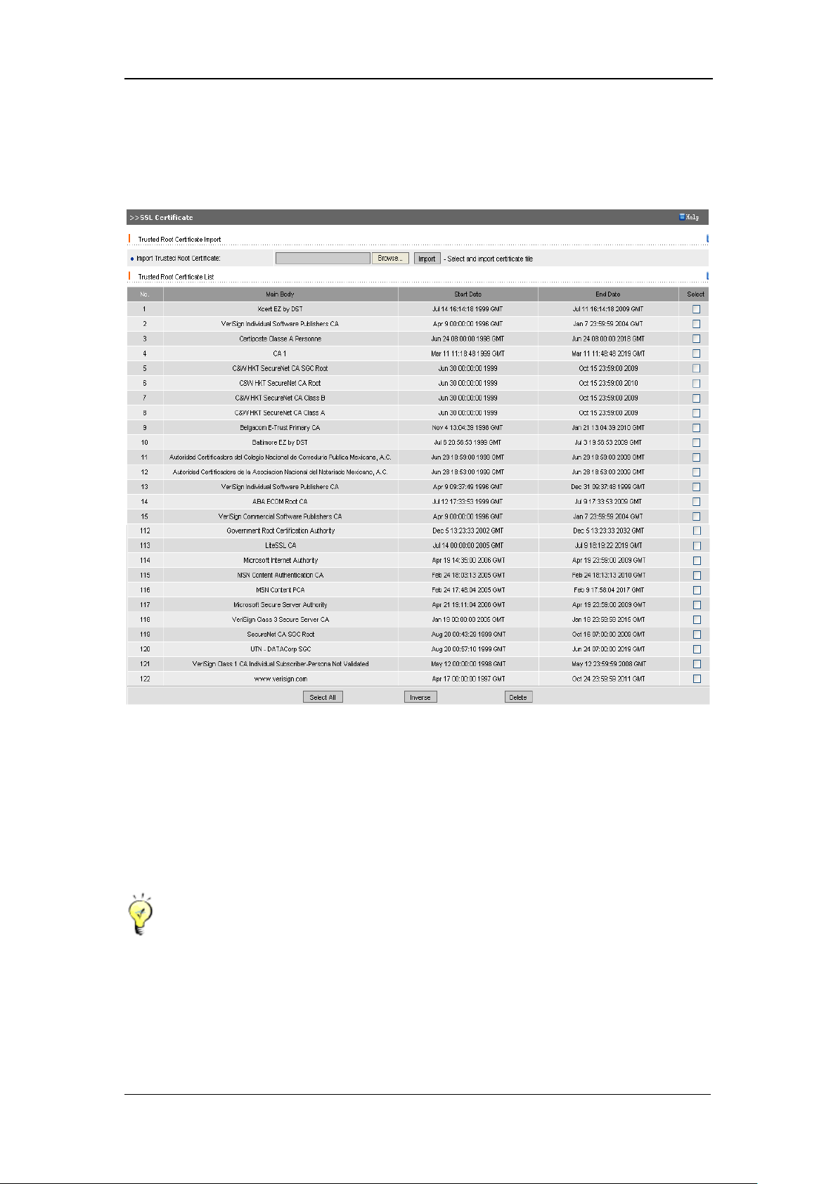
SANGFOR IAM v2.1 User Manual
81
root certificates in the library are trusted. You can import trusted root certificate to the [Trusted
Root Certificate List] or delete a trusted root certificate.
The related page is as shown below:
[Import Trusted Root Certificate]: Import certificate from the local PC, only support crt or cer
format certificate.
Differentiation of different certificates is inspected by MD5 value of the certificate. If the MD5
value of a certification is different from others, then it is regarded as another certificate.
A certificate cannot be imported twice or more.
Generally, name of the certificate main body is the corresponding CN name of the
certificate subject in IE. If the certificate subject contains no CN name, it will take the last field of
the subject as the main body of the certificate (the field order may be different from that of IE).
Page 83
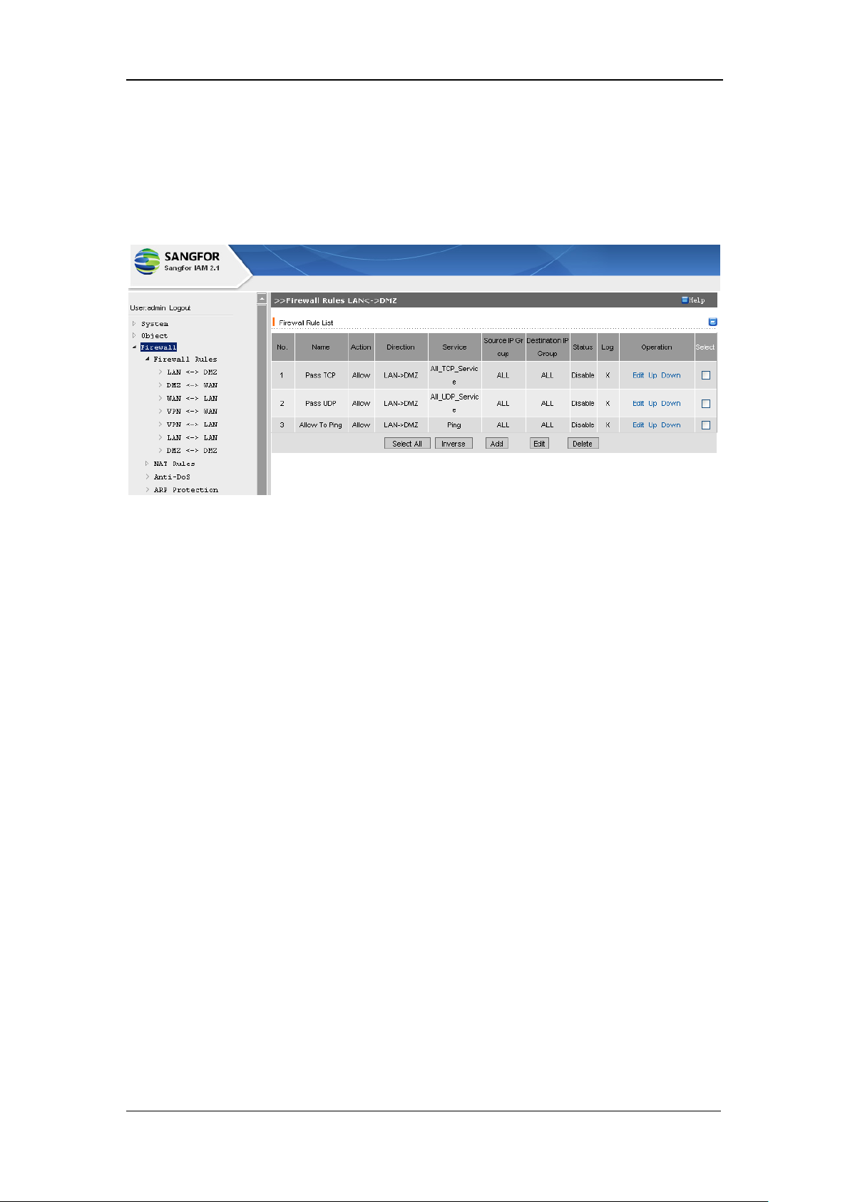
SANGFOR IAM v2.1 User Manual
82
Chapter 5 Firewall
[Firewall] covers configurations of [Firewall Rules], [NAT Rules], [Anti-DoS] and [ARP
Protection], as shown below:
5.1. Firewall Rule
[Firewall Rule] configures the specific settings of data packet access. IAM gateway device allows
you to configure the filtering rules for data transmission between [LAN<->DMZ],
[DMZ<->WAN], [WAN<->LAN], [LAN<->LAN], [DMZ<->DMZ], [VPN<->WAN] and
[VPN<->LAN].
5.1.1. LAN <-> DMZ
[LAN <-> DMZ] configures the rule for data transmission fulfilled between LAN interface and
DMZ interface. The service can be all the services of certain protocol or a user-defined service.
For example, to have the communication between the LAN interface and DMZ interface available,
you have to enable all the TCP, UDP and ICMP services and have them available for both
directions, LAN > DMZ and DMZ > LAN. By default, all the TCP, UDP, ICMP services are
accessible for [LAN->DMZ]; however, if the rule is not enabled, the [Status] displayed in the
[Firewall Rule List] is [Disable], as shown below:
Page 84
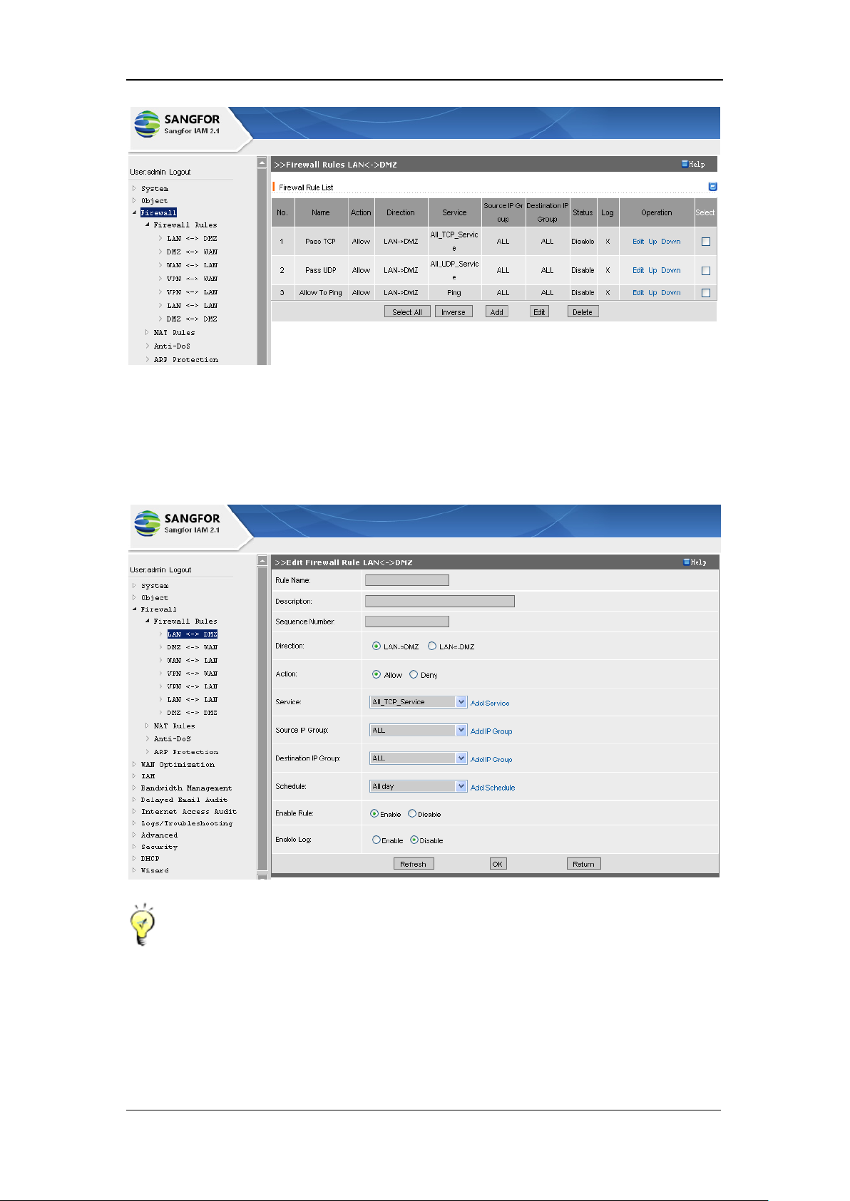
SANGFOR IAM v2.1 User Manual
83
Under the above configuration page, click the <Edit> button and the [Edit Firewall Rule
LAN<->DMZ] configuration page. Click the <Enable> button to enable this rule; or click the
<Add> button and the [Edit Firewall Rule LAN<->DMZ] configuration page pops up, as shown in
the following figure:
Firewall rules are to be matched from top to bottom. If a rule is matched, the rules below it
will not to be matched, therefore, please arrange the rules in needed order. Order arrangement
of the firewall rules cannot only be fulfilled through the [Firewall Rule List], but be
numbered by [Sequence Number] (in the above figure).
The Firewall defaults to deny the data packets if none of the firewall rules is matching, that is
Page 85
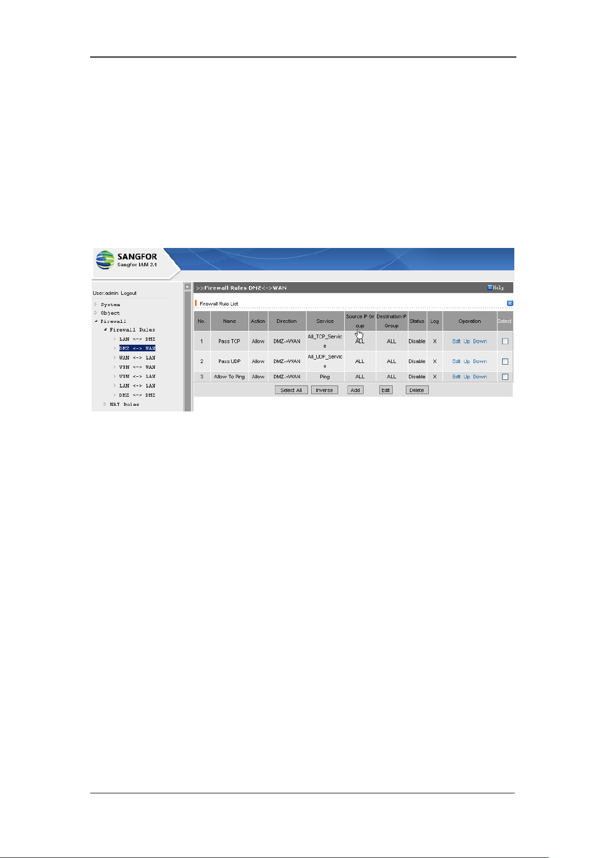
SANGFOR IAM v2.1 User Manual
84
to say, the data packets will be dropped.
5.1.2. DMZ <-> WAN
[DMZ <-> WAN] configures the rule for access fulfilled between WAN interface and DMZ
interface. The service can be all the services of certain protocol or a user-defined service(s). For
detailed configuration, please refer to Section 5.1.1 LAN <-> DMZ.
The default configuration page is as shown below:
5.1.3. WAN<->LAN
[WAN <-> LAN] page configures the rule communication between the LAN interface and the
WAN interface. By default, Internet access through the LAN interface has no limitation, while
LAN access through the WAN interface is not allowed. To enable the external network to access a
local area network, you have to configure a filtering rule which allows the Internet IP to access the
LAN IP address.
As shown in the figure below, the port configured for Internet IP to access the local area network
is 80, which indicates the port for communication from [WAN->LAN] is 80.
Page 86
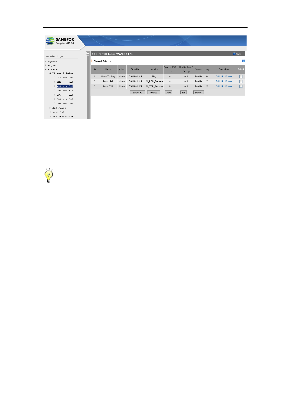
SANGFOR IAM v2.1 User Manual
85
In the [Firewall Rule List], information of [Service], [Source IP Group], [Destination IP Group]
can be configured in the corresponding page of [Object] or you can click the <Add> button
followed to create a new one. For detailed configuration of each object, please refer to the
corresponding section in Chapter 4 Object.
[WAN<->LAN] is a most common firewall rule. The IAM gateway device has some
built-in and frequently-used firewall rules which default to let pass all the data packets from the
external networks.
5.1.4. VPN <-> WAN
[VPN<->WAN] configures the firewall filtering rule for data transmission fulfilled between the
VPN interface and WAN interface. If the VPN client connects to the headquarters‟ VPN device
and gets access to the Internet through it, you then can configure the filtering rule of
[VPN<->WAN] on the headquarters‟ VPN device to control the Internet access request sent from
the client terminal (branch VPN user or mobile VPN user).
The configuration page is as shown below:
Page 87
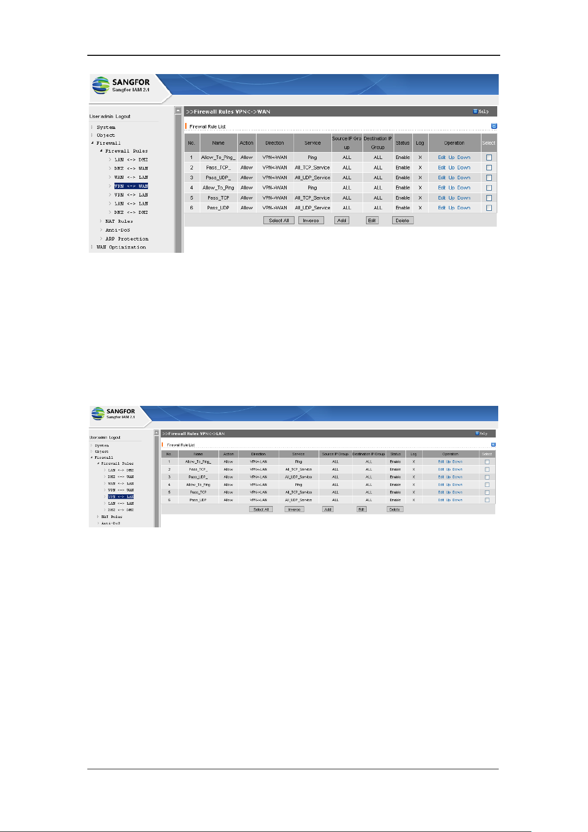
SANGFOR IAM v2.1 User Manual
86
5.1.5. VPN<->LAN
[VPN<->LAN] configures the rule for data transmission between the VPN interface and the DMZ
interface. By default, TCP, UDP and ICMP data transmission of both directions between the
interfaces are allowed.
The configuration page is as shown below:
For instance, to allow the IP addresses (172.16.1.100-172.16.1.200) of a Branch VPN
(172.16.0.0/24) to get access to the WEB server (192.168.1.20) of the headquarters and ban it
from accessing to the SQL SERVER, you need first to create a filtering rule on WEB server.
Detailed configuration is shown in the following figure:
Page 88
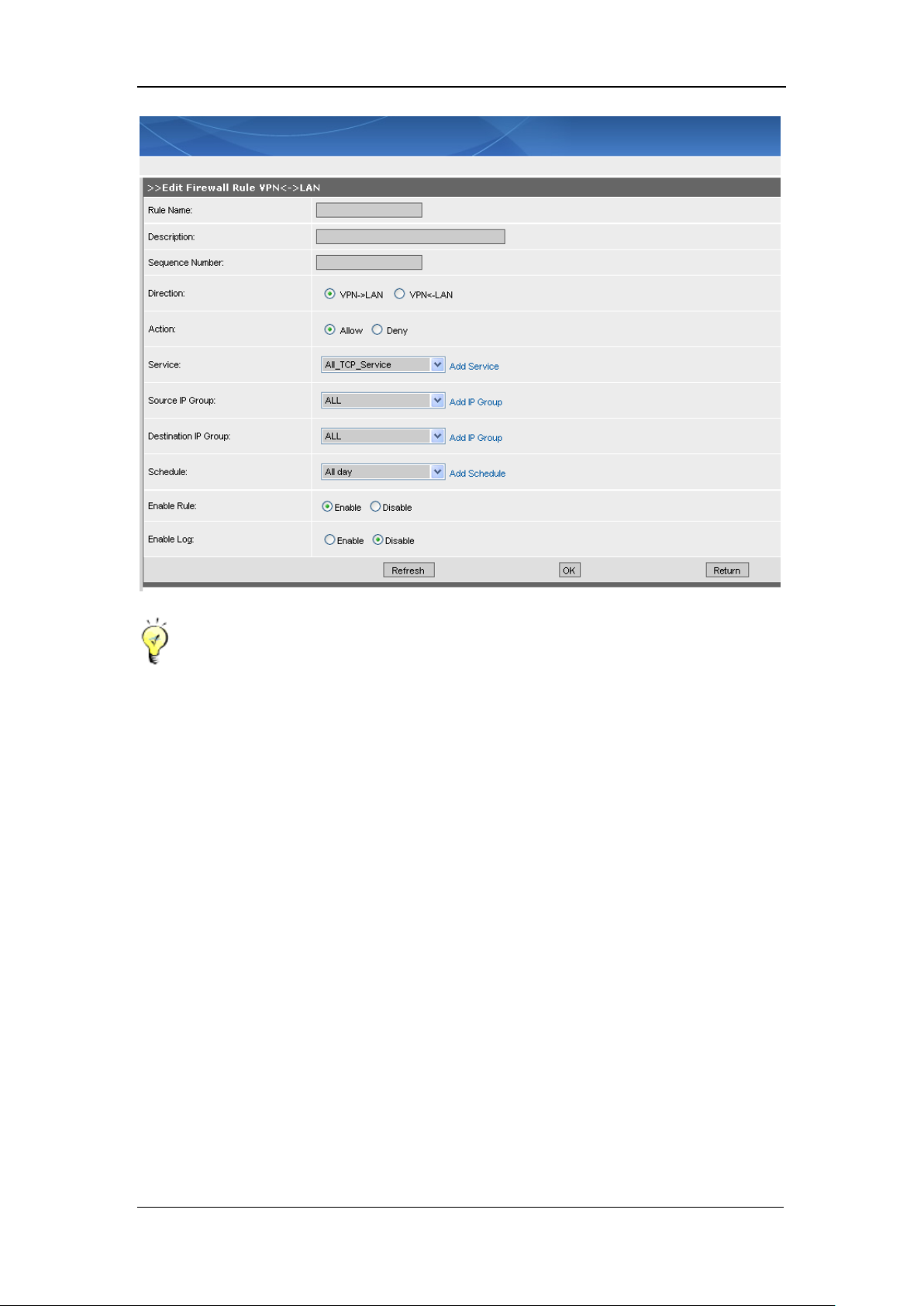
SANGFOR IAM v2.1 User Manual
87
As to other kinds of data packets from the VPN headquarters or the Branch VPN, you can
also configure filtering rule(s) for the data transmission between other interfaces.
5.1.6. LAN<->LAN
[LAN <-> LAN] configures the data transmission between the LAN1 interface (LAN interface on
the IAM gateway device) and the LAN2 interface (the idle WAN2 interface on the IAM gateway
device), or configures the communication among the IP addresses (of different segments) that are
bound with the LAN interface. The service can be all the services of certain protocol or a
user-defined service. For detailed configurations, please refer to Section 5.1.1 LAN <-> DMZ.
The default configuration page is as shown below:
Page 89
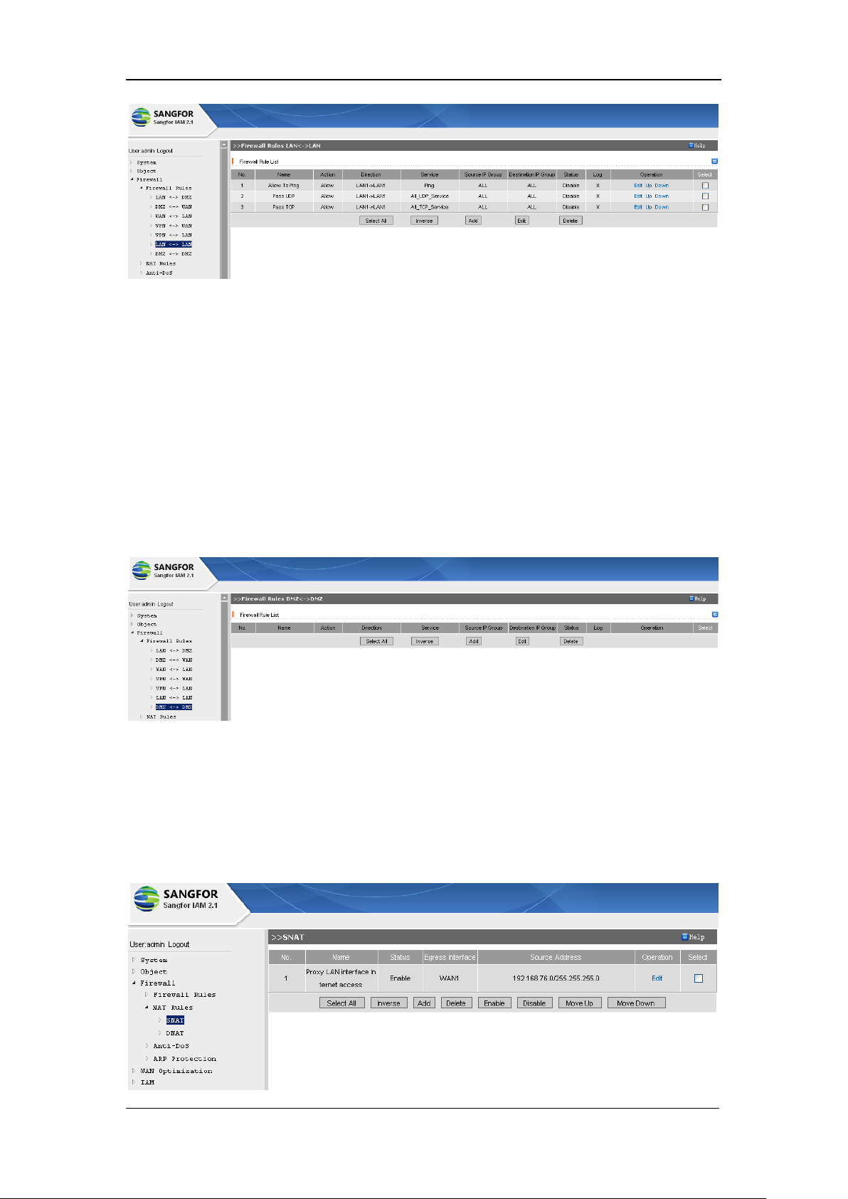
SANGFOR IAM v2.1 User Manual
88
5.1.7. DMZ <-> DMZ
[DMZ <-> DMZ] configures the data transmission between the DMZ1 interface (DMZ interface
on the IAM gateway device) and the DMZ2 interface (the WAN2 interface on the IAM gateway
device), or configures the communication among the IP addresses (of different segment) that are
bound with the DMZ interface. The service can be all the services of certain protocol or a
user-defined service. For detailed configurations, please refer to Section 5.1.1 LAN <-> DMZ.
The default configuration page is as shown below:
5.2. NAT Rules
[NAT Rules] covers [SNAT] and [DNAT] configurations. The default configuration page is as
shown below:
Page 90
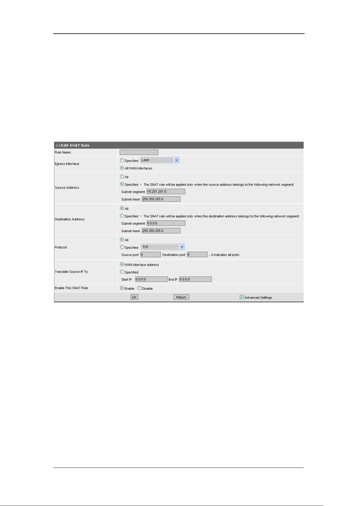
SANGFOR IAM v2.1 User Manual
89
5.2.1. SNAT
Provided that a LAN IP address is 192.168.1.0./255.255.255.0, to create a SNAT (source network
address translation) rule to proxy all the LAN users to get access to the Internet, you need to
configure the followings.
Under the default configuration page of [SNAT Rules], click the <Add> button to enter the [Edit
SNAT Rule], as shown below:
Type in a [Rule Name] to name this rule.
Select an [Egress Interface], a specified network interface or select [All WAN interfaces] to which
the data packets are forwarded to.
Select [Source Address], [All] the IP addresses or a [Specified] subnet, which can get access to the
Internet through the IAM gateway. In this example, the configured source address is the subnet
10.251.251.0/255.255.255.0.
Configure [Translate Source IP to], [WAN interface address] or [Specified] IP addresses.
[Specified] requires [Start IP] and [End IP] (they are only required while the IP address and line is
specified for Internet access). Generally, we select [WAN interface address] which means the
source address can access all the public IP addresses through the WAN interface(s).
Page 91
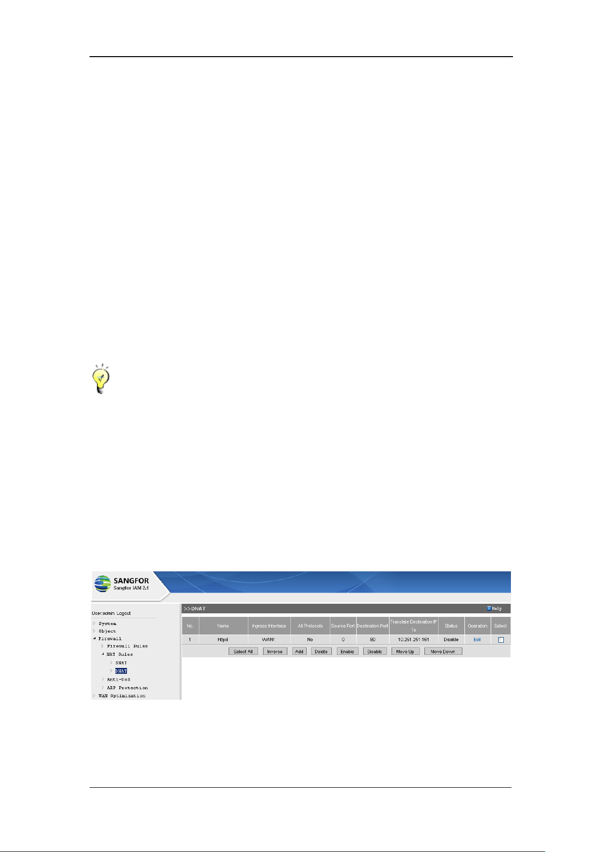
SANGFOR IAM v2.1 User Manual
90
If [Advanced Settings] is checked, more settings are seen. Detailed introductions are as follows:
[Destination Address]: Options are [All] and [Specified]. [All] means all the destination IP
addresses, while [Specified] indicates that the destination addresses are the specified ones.
[Destination Address] and [Source Address] can be configured at the same time. If both of them
are configured, only when both of the conditions are satisfied will the source translation (SNAT)
rule will be fulfilled; if only one of the conditions is configured, then only the corresponding
condition needs to be satisfied.
[Protocol]: Options are [All] and [Specified]. [All] indicates all the protocol on which the SNAT
rule is applied; [Specified] is selected and entered when the protocol and line applied are
specified.
Having completed configuring this page, you have to click the <OK> button to save the settings.
Firewall rule [LAN->WAN] has to be configured to allow the data transmission.
5.2.2. DNAT
If a LAN (local area network) server needs to provide Internet with services, the [DNAT] function
of IAM gateway device has to be configured.
The default configuration page of [DNAT] rule is as shown below:
Provided that a LAN PC (IP address: 10.251.251.61) wants to provide the external network with
WEB services, at port 80, follow the procedures below to configure a DNAT rule:
Under the [DNAT] configuration page, click the <Add> button to enter the [Edit DNAT Rule]
Page 92
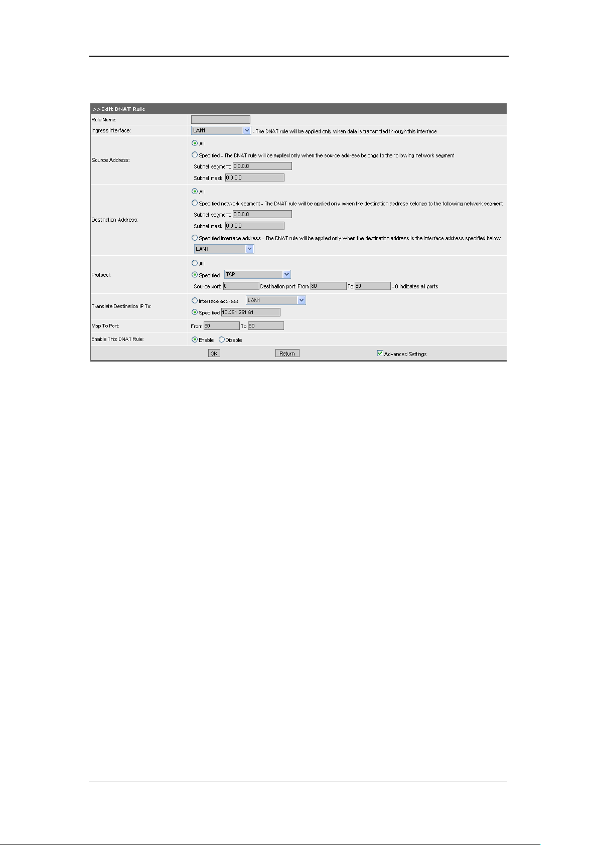
SANGFOR IAM v2.1 User Manual
91
page, as shown below:
Type a [Rule Name] to name this DNAT rule;
Select an [Ingress Interface];
Select a [Protocol], [All] the protocols or the [Specified] protocol TCP; enter [Source port] 0
(indicates all the ports), [Destination port] 80~80;
Enter the [Translate Destination IP To] 10.251.251.61;
Enter the [Map To Port] 80~80.
If [Advanced Settings] is checked, more settings are seen. Detailed introductions are as follows:
[Source Address]: Options are [All] and [Specified]. [All] means all the source IP addresses, while
[Specified] indicates that the source addresses are the specified ones.
[Destination Address]: Generally, [Specified interface address] is selected. If the WAN interface
has several IP addresses, you can select the [Specified network segment] to specify the WAN
interface IP address or IP range which are then be translated to the IP address of the local area
network.
[Destination Address] and [Source Address] can be configured at the same time. If both of them
are configured, only when both of the conditions are satisfied will the SNAT rule will be fulfilled;
if only one of the conditions is configured, then only the corresponding condition needs to be
Page 93
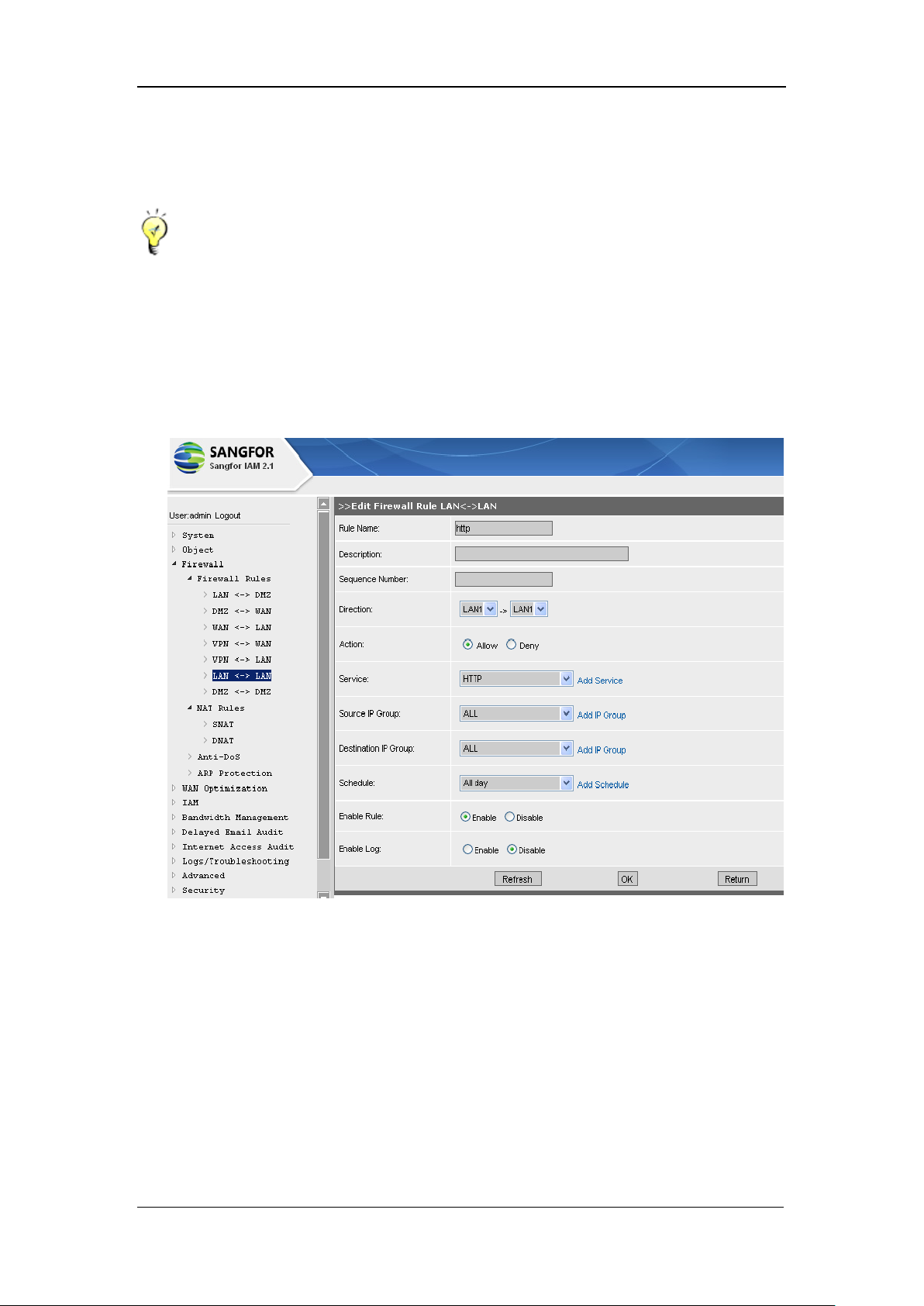
SANGFOR IAM v2.1 User Manual
92
satisfied.
Having completed configuring this page, you have to click the <OK> button to save the settings.
If the [Source port] of TCP [Protocol] is configured as 0, it indicates all the ports.
Settings of allowing any Internet IP address to access the LAN IP 10.251.251.61 at port 80
are configured in [Firewall] > [Firewall Rules] > [WAN<->LAN] page. For details, please
refer to Section 5.1.3 WAN<->LAN. The configuration page is as shown below:
5.3. Anti-DoS
DoS attack (Denial of Service attack), generally is implemented by forcing the server to reset or
saturating the server with external communication requests and consuming its resources, so that it
can no longer provide intended service and respond to legitimate computers. SANGFPR IAM
gateway device can defend the local area network against DoS attacks from external networks,
and take measures to prevent the infected machine or attack tool from initiating DoS attacks. It
can locate the attack source with the IP and MAC information
Page 94
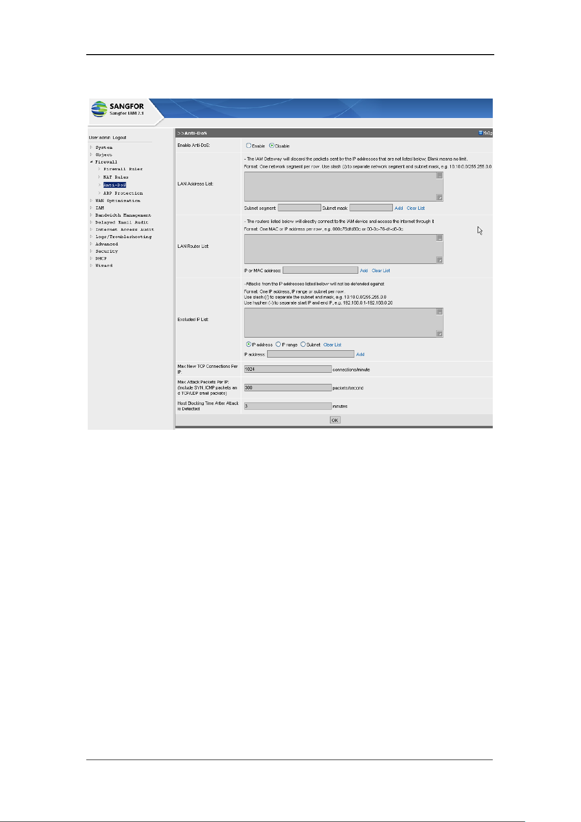
SANGFOR IAM v2.1 User Manual
93
The configuration page is shown below:
[Enable Anti-DoS]: Select [Enable] to enable the anti-DoS function.
[LAN Address List]: Configures the LAN IP range which gets access to the Internet through the
SANGFOR IAM gateway device. The data packets from the IP addresses outside the [LAN
Address List] will be dropped by the IAM gateway device, which means these blocked IP
addresses will fail to connect to the Internet through the IAM gateway device or connect to the
IAM gateway device through LAN and DMZ interface (mistakes made on this list may result in
login failure to the console through the LAN interface; in that case, log in through the WAN
interface). The [LAN Address List] can be left blank, but configuring it will enable the
SANGFOR IAM gateway device to defend against DoS attacks, such as attacks by masqueraded
IP address.
[LAN Router List]: Configures the router (without enabling NAT function) or layer 3 switch that
connects to the LAN interface or DMZ interface of the IAM gateway device. If a PC is not at the
same segment of the LAN interface or DMZ interface of the IAM gateway device, the MAC
address of this PC will be replaced by the MAC address of the routing device. In case the number
of connections of this routing device is more than expected, the routing device's interface (at the
Page 95

SANGFOR IAM v2.1 User Manual
94
same segment with IAM gateway device) will be blocked by the IAM gateway device. This [LAN
Router List] will prevent the MAC address of the LAN router (in the list) from being blocked by
the IAM gateway device.
You can enter interface IP address or MAC address of the router (or layer 3 switch) that directly
connects to the LAN interface of the IAM gateway device. The IAM gateway device will
automatically distinguish the MAC address of the corresponding IP address.
[Excluded IP List]: Configures the IP address(es) that will not be defended against in any case,
regardless of the number of connections and high frequency of sending packets. Generally, the
connections and frequency of sending packet of an IP address is limited; if any of the standards is
reached, it will be regarded as DoS attack.
[Max New TCP Connections Per IP]: Configures the maximum TCP connections of each IP
allowed by the IAM gateway device in one minute. If number of new TCP connections of an IP
address exceeds the limit configured herein, the IP will be blocked for a certain time ([Host
Blocking Time After Attack is Detected]).
[Max Attack Packets Per IP]: Configures the maximum packets (including SYN packets, ICMP
packets and TCP/UDP small attack packets) of each IP or MAC address allowed by the IAM
gateway device in one second. If number of them exceeds the limit configured herein, the IP or
MAC address will be blocked for a certain time ([Host Blocking Time After Attack is Detected]).
[Host Blocking Time After Attack is Detected]: Configures the time duration of blocking the host
if the IAM gateway device detects that this host is initiating attacks; in unit of minutes.
It is strongly recommended to enable the anti-DoS function, which will enable the IAM
gateway device to efficiently defend attacks initiated by external networks and to prevent
traffic congestion caused by enormous and continuous packets that are sent by the
virus-infected LAN PC.
[LAN Address List] is also recommended to be configured. This configuration will help to
defend against attacks initiated by masqueraded IP address. Better to add all the LAN
segments to the list, for the data packets sent by the IP addresses outside the list will be then
forwarded to the IAM gateway device and then be dropped.
If there is a LAN router or layer 3 switch, please DO add the routing device's interface IP
Page 96

SANGFOR IAM v2.1 User Manual
95
(that directly connects to the IAM gateway device) to the [LAN Router List], so that the
MAC address of this interface is excluded from the anti-DoS rule and from being blocked.
Generally, if the WAN interface of the IAM gateway device connects to any firewall or router,
the interface IP address of this routing device should be added into the [LAN Router List].
By default, the [Max New TCP Connections Per IP] in one minute of an IAM gateway device
anti-DoS module is 1024, and the [Max Attack Packets Per IP] is 300. If the local area
network is virus-infected and sending enormous packets, resulting in disconnection of the
network, it is recommended to modify [Max New TCP Connections Per IP] to 512 and [Max
Attack Packets Per IP] to a smaller value, and then the defense against the LAN
virus-infected computers can be more efficient.
As the download software Thunder allows massive connections, and thus features like DoS
attack. Because of this feature, the IAM gateway device may block the LAN PC that is
running Thunder software. To solve this problem, you can set an appropriate value to lower
the possibility the computer being blocked by the IAM gateway device. Configure the [Max
New TCP Connections Per IP] as 1024 connections/minute and [Max Attack Packets Per IP]
as 512 packets/second.
5.4. ARP Protection
ARP spoofing is a common LAN virus. The infected computer keeps sending fake (or spoofed)
message (broadcast packets) to the local area network (LAN), and thus interrupts and stops the
normal communication among the LAN devices, or even stops the overall traffic of the local area
network.
Defense against ARP spoofing is fulfilled through the ARP protection function of IAM gateway
device in association with the Ingress Client installed in the LAN PC. After installing the Ingress
Client, the Ingress Client will communicate with the IAM gateway device to get the correct
IP/MAC information of the gateway device and bind with it. The IAM gateway device will refuse
to receive the ARP request or response that features attack, so as to protect the ARP cache of the
local IAM gateway device and get immune from ARP spoofing.
However, if the user related to access control policy is bound with an IP/MAC address(es), the
IAM gateway device will take the bound ones (in [Organization Structure] > [Edit User] page >
[Advanced Settings] > [User Attribute]) as the final IP/MAC address(es).
Page 97
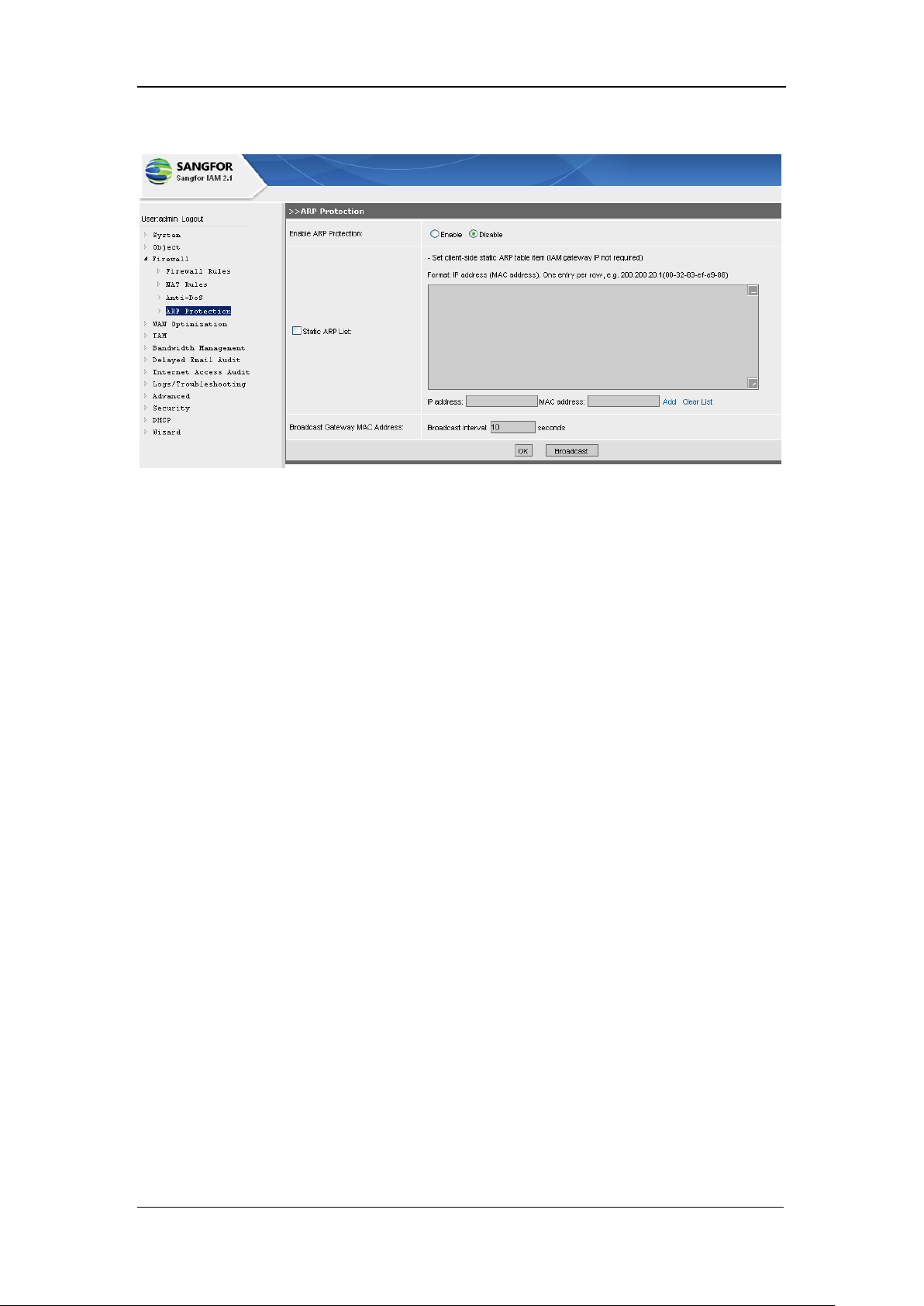
SANGFOR IAM v2.1 User Manual
96
The configuration page is as shown below.
[Enable ARP Protection]: Select [Enable] to enable the ARP spoofing protection function.
[Static ARP List]: If the gateway of the LAN PC is not an interface IP address of the IAM gateway
device, the [Static ARP List] should be configured. Provided that, the gateway mode of the IAM
gateway device is Bridge mode; the gateway address of the LAN PC is the interface IP address of
its front-end router (or firewall), in this case, we have to add the IP/MAC address of the front-end
router to the [Static ARP List]. If the LAN PC has installed the Ingress Client, then it can get the
correct IP/MAC address of the gateway and bind with it; therefore, we can make sure that the
IP/MAC address of the gateway is correct.
[Broadcast Gateway MAC Address]: Indicates the frequency broadcasting the MAC address of the
gateway (the LAN interface of the IAM gateway device), in unit of second.
<Broadcast>: Click this button to manually and immediately broadcast the MAC address of the
device‟s LAN interface. When the ARP spoofing is eliminated, clicking this button can restore the
ARP table of the LAN PC swiftly.
Having completed configuring this page, you have to click the <OK> button to save the settings.
Page 98
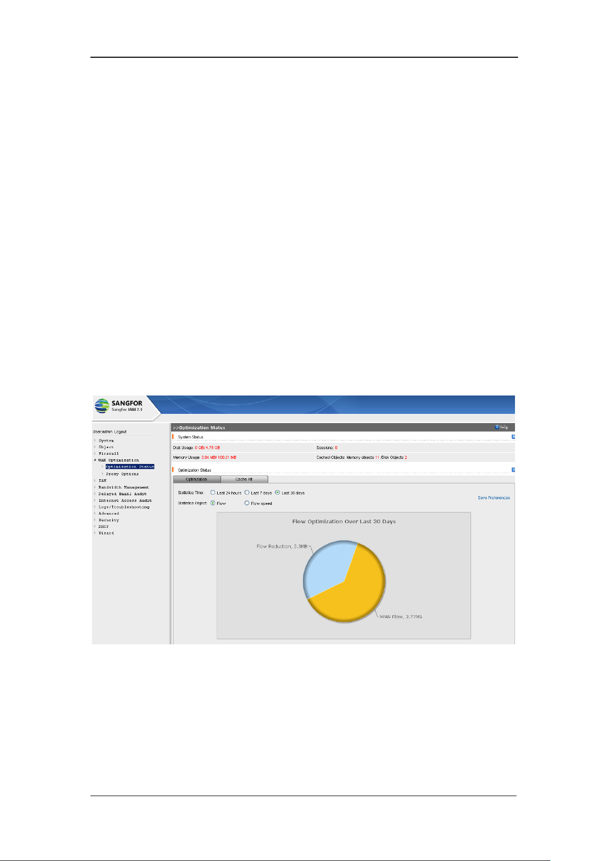
SANGFOR IAM v2.1 User Manual
97
Chapter 6 WAN Optimization
In a real enterprise network, the bandwidth resources are limited and bandwidth resources waste
also exists. It is possible that thousands of LAN users visit a well-known website and the same
data have to be transmitted thousands of times or more, which consumes and wastes massive
bandwidth resources.
The SANGFOR IAM gateway device will help to solve this problem. The preliminary data
requested by a LAN user who visits this website for the first time will be cached by the IAM
gateway device, if a second LAN user wants to visit the same website, the requested data
(basically the same with the data requested by the first LAN user) will be directly fetched from the
cache; the user need not request data resources over the Internet.
[WAN Optimization] covers [Optimization Status] and [Proxy Options]. The cache function can
accelerate HTTP application and improve the speed of visiting websites.
The default page is as shown below:
6.1. Optimization Status
[Optimization Status] displays the cache and optimization (acceleration) information, including
[System Status] and [Optimization Status] modules, as shown below:
Page 99
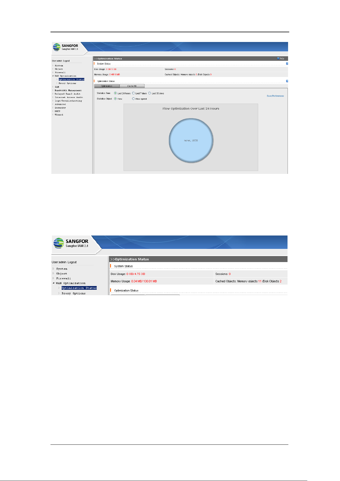
SANGFOR IAM v2.1 User Manual
98
6.1.1. System Status
[System Status] displays the disk usage, sessions, memory usage and cached objects information,
as shown below:
[Disk Usage]: Displays the utilized disk space by and the available disk space for optimization.
[Sessions]: Refreshes and displays the total current sessions every five minutes.
[Memory Usage]: Displays the utilized memory by and the maximum available memory space for
optimization.
[Cached Objects]: Displays the total cached objects in the memory and the total objects in the
disk.
6.1.2. Optimization Status
[Optimization Status] displays the [Optimization] and [Cache Hit] information, as shown below:
Page 100
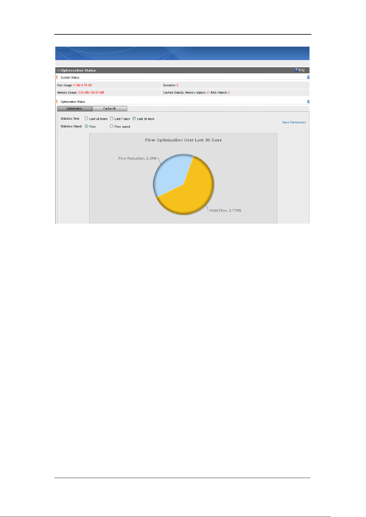
SANGFOR IAM v2.1 User Manual
99
[Optimization] displays two kinds of statistics objects, one is [Flow], and the other is [Flow
Speed], in time unit of [Last 24 hours], [Last 7 days] or [Last 30 days].
[Flow]: Makes statistics of traffic volume passing through and the traffic volume saved by the
WAN optimization module. The saved traffic volume indicates the data (cached in the IAM
gateway device) being matched by the sequential visits to the extranet server, that is, volume of
the data request directly responded by the IAM gateway device. This part of traffic volume shows
the external bandwidth saved by the IAM gateway device.
[Flow speed]: Displays the flow speed of the data that are passing through the IAM WAN
optimization module. The information is displayed on rectangular coordinates, X axis in unit of
time and Y axis in unit of flow speed.
Flow speed are [LAN Flow Speed] and [WAN Flow Speed]. [LAN Flow Speed] means the flow
speed the IAM gateway device directly responded to the LAN user‟s website access requests.
These portions of data do not reach the public network, and thus consumes no public bandwidth.
[WAN Flow Speed] means the flow speed of the data that the IAM gateway device forwarded to
the extranet server plus that of the extranet network giving response to the LAN user‟s request.
 Loading...