

Page 1
Contents
APPLICATION GUIDE
Threading
Thread turning and thread milling
Introduction
1 Basics in threads
2 Applications
Threading methods
Thread turning vs thread milling
Thread Turning
Thread Milling
3 Products
Thread Turning
CoroThread® 266
CoroCut® XS
CoroTurn® XS
CoroCut® MB
T-Max Twin-Lock®
Extended offer
Thread Milling
CoroMill® 327
CoroMill® 328
CoroMill® Plura
Grade information
2
3
9
10
14
35
46
48
56
58
60
62
64
65
67
69
70
72
4 Troubleshooting
5 Technical reference
Cutting data
Programming
Thread turning infeed recommendations
External thread milling recommendations
Formulas
Inch/mm conversion table
76
86
92
96
112
114
118
Page 2

ntr
oduction
Introduction
Modern threading tools can produce complex component features
with relative ease, but to gain consistent results there are a number of considerations to be made.
In this application guide, we show you how to achieve threading
success with Sandvik Coromant tools. Our aim is to help you to
choose the right tooling combinations to produce consistent, high
quality threads and guide you towards the most productive and
problem-free threading performance.
This guide also includes information on basic threading principles
- together with deeper application information, troubleshooting
advice and nally, a technical reference section to cover all of your
thread machining needs.
2
Page 3
.
Basic in threads
1. Basics in threads
What is a thread?
Threads are classi ed according to the main functions they perform in a component.
Primary functions of a thread:
• To form a mechanical coupling
• To transmit motion by converting a rotational movement into a linear movement, and vice
versa.
• To obtain a mechanical advantage, by using a small force to
create a larger force.
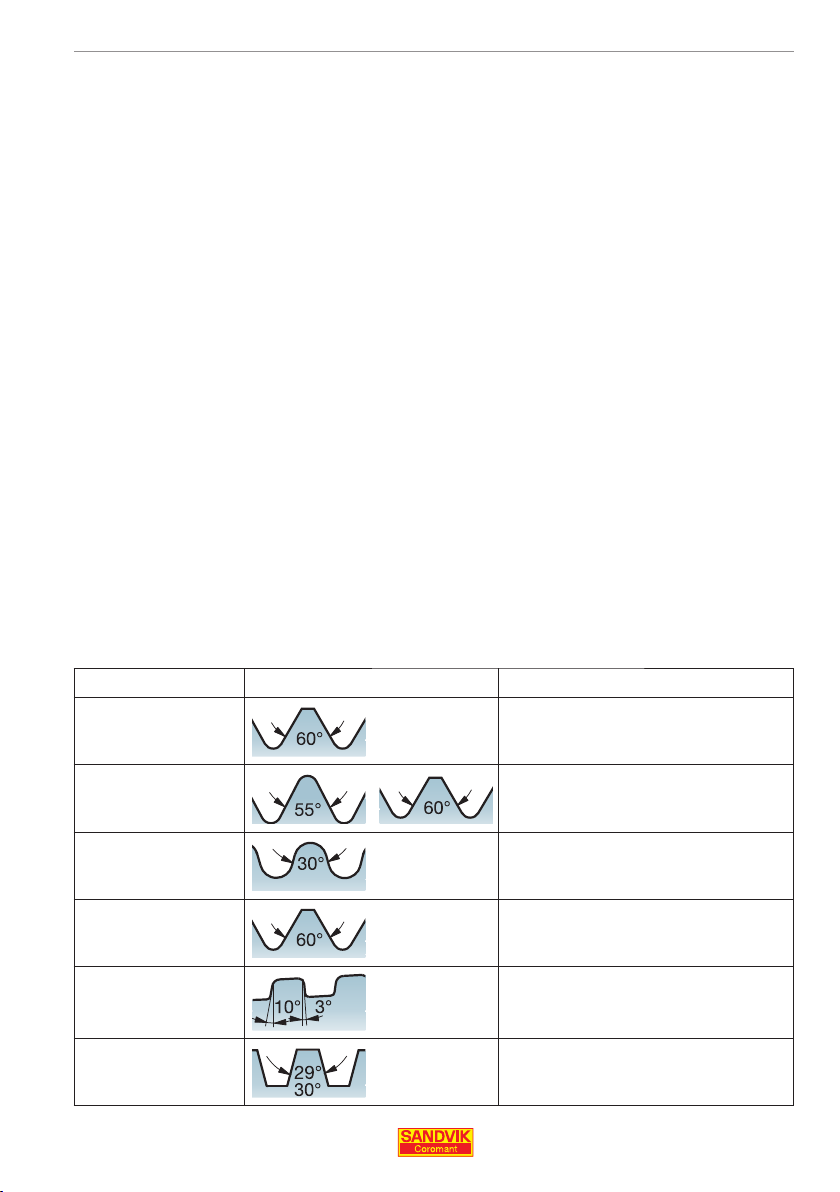
Threads are also classi ed into various pro les or forms. The selection of these forms will
be in uenced by many other secondary, but still vital, functions.
Thread forms
The thread pro le de nes the geometry of a thread and includes component diameters
(major, pitch and minor), the thread pro le angle, pitch and helix angle. The most common
thread forms or pro les produced today are shown below.
Application Thread form Thread type
Connecting
General usage
Pipe threads Whitworth, British Standard (BSPT),
Food and re Round DIN 405
Aerospace MJ, UNJ
Oil and gas API Rounded, API Buttress, VAM
Motion
General usage
ISO metric, American UN
American National, Pipe Threads,
NPT, NPTF
Trapezoidal, ACME, Stub ACME
3
Page 4
.
Basic in threads
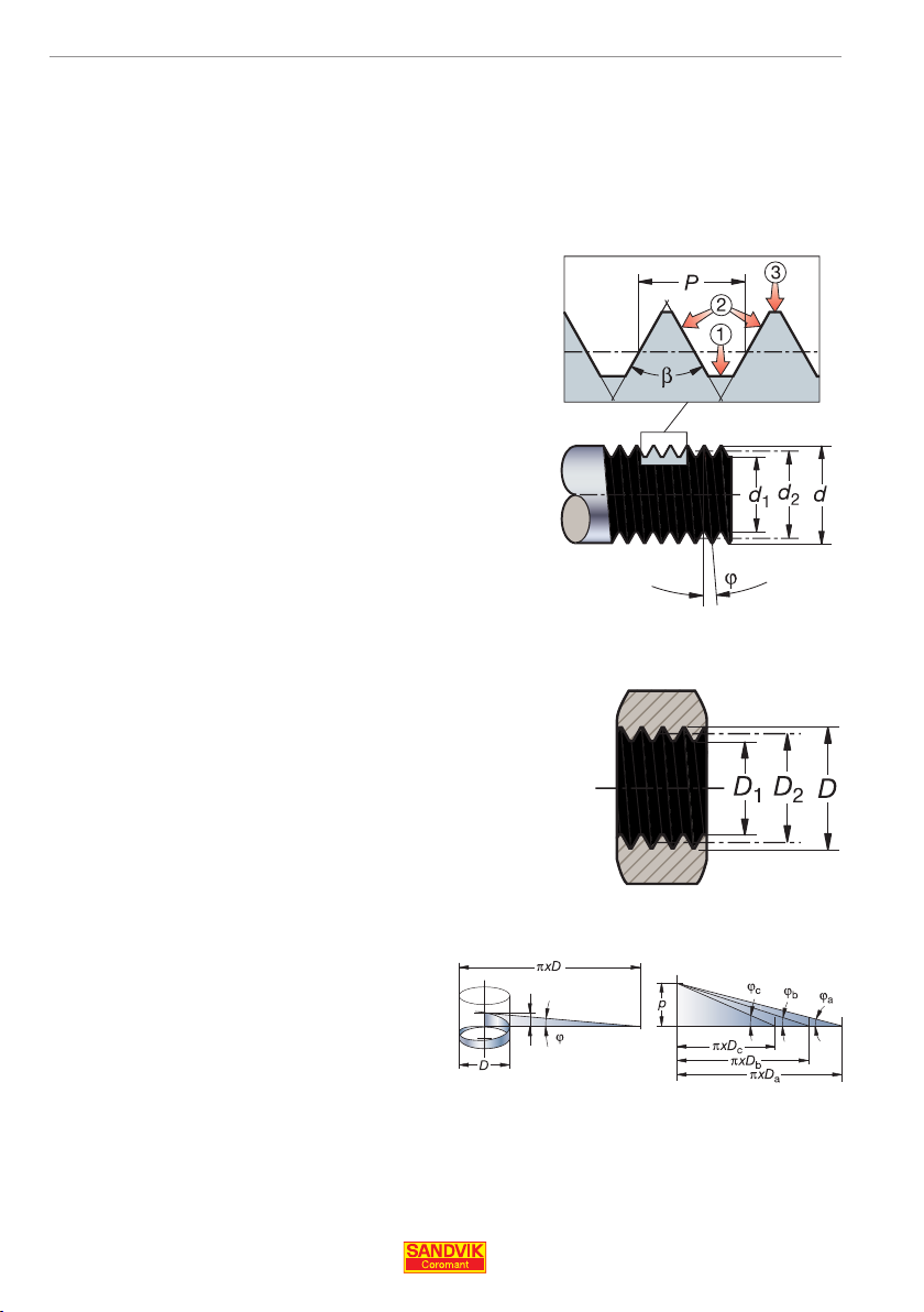
Threading terms and de nitions
1. Root/bottom
The bottom surface joining the two adjacent anks of
the thread
2. Flank/side
The side of a thread surface connecting the crest and
the root
3. Crest/top
The top surface joining the two sides, or anks.
P = Pitch, mm or threads per inch (t.p.i.)
= The pro le angle
= The helix angle of the thread
d / D = The major diameter, external/internal
d
/ D1 = The minor diameter, external/internal
1
d
/ D2 = The pitch diameter, external/internal
2
Pitch diameter, d2 / D
2
This is the effective diameter of the screw
thread; approximately half way between the
major and minor diameters.
Helix angle
The helix angle ()is the geometrical shape
of the screw thread, it is based on the pitch
diameter of the thread (d
pitch (P) – the distance from one point on a
thread pro le to the corresponding point on
the next.
This measurement can be represented by
a triangle being unwound from the component.
4
, D2), and the
2
The same pitch on different diameters gives a different helix angle,
see example above.
Page 5

ds
Thread designations
International standards
To ensure that the two (internal and external) halves of a threaded
joint t together properly to produce a connection capable of bearing a speci ed load, threads must maintain certain standards.
International standards for thread forms have therefore been established for all common thread types.
Below are examples of Metric, UN and Whitworth thread designations.
ISO metric thread designations
The complete thread designation is made up of values for the
thread form and the tolerance. The tolerance is indicated by a number for the tolerance grade, and letters for the tolerance position.
. Basic in threa
Examples:
M16 - 6h
Thread designation and nominal dimension
Tolerance class for pitch and crest position
Pitch
Tolerance class for pitch diameter
Tolerance class for crest diameter
M10 x 1.25 5g6g
A t between threaded parts is indicated by the internal thread tolerance class
followed by the external thread tolerance class, separated by an oblique stroke.
5
Page 6
.
Basic in threads
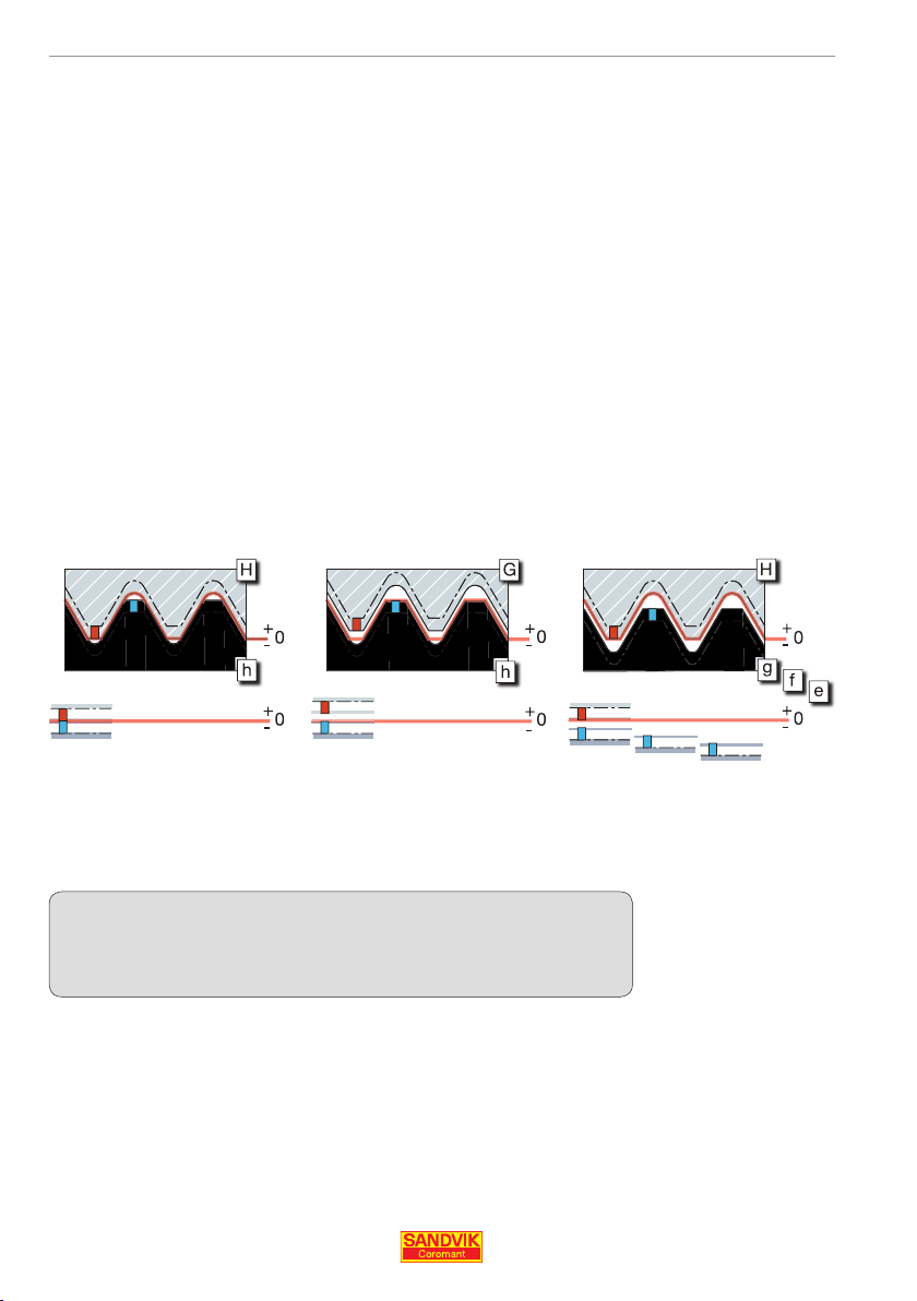
Tolerance positions
The tolerance position identi es the fundamental deviation and is
indicated with an upper-case letter for internal threads and a lower
case letter for external threads. A combination of tolerance grade and
position give the tolerance class. The values of the tolerance classes
are given in the standards for the different threading systems.
Tolerance positions
Internal threads H and G
External threads h, g, f and e
6
Page 7

ds
ISO inch threads (UNC, UNF, UNEF, UN)
The UN system has three tolerance classes, ranging from 1
(course) to 3 ( ne). A typical UN thread is designated as follows:
¼” 20UNC – 2A
2A – Indicates a medium tolerance
UNC – Indicates a course pitch
20 – Pitch value: threads per inch (t.p.i.)
¼” – Major thread diameter
ISO - uni ed (UN):
. Basic in threa
Loose tolerance
Medium tolerance
Tight tolerance
Tolerance position
Types of UN thread
UNC thread diameter with course pitch
UNF thread diameter with ne pitch
UNEF thread diameter with extra- ne pitch
UN thread diameter with constant pitch
All of the above types of thread can be created using the UN insert
from Sandvik Coromant
The pitch value is indicated in t.p.i. (threads per inch).
To convert to metric, this should be divided by 25.4 using the
following equation:
1A 1B
2A 2B
3A 3B
20 t.p.i. 25.4/20 = 1.27 mm.
7
Page 8
.
Basic in threads
Whitworth threads (G, R, BSW, BSF, BSPF)
Whitworth screw threads are now obsolete, but Whitworth pipe
threads are a recognized international standard. There are two
tolerance classes for external-, and one tolerance class for internal
Whitworth pipe threads.
Whitworth pipe thread designations
These threads are divided into 2 groups:
• Pressure-tight joints not made on the thread, ISO 228/1
• Pressure-tight joints made on the thread, ISO 7/1
Whitworth pipe threads:
BSW
BSF
BSP.F
Fine Only
Coarse
A
B
one
class
Tolerance position
Examples of Whitworth pipe thread designations:
Pressure tight joints not made on the thread:
ISO 228/1 G
= G 1 ½ A
(external)
= G 1 ½ (internal)
= parallel thread
= pipe diameter, not thread diameter
1 ½
A or B = external tolerance class only
Pressure tight joints made on the thread:
ISO 7/1 = R
7/1 = Rc 1 ½R
7/1 = R 1 ½R
Sandvik Coromant’s WH inserts are to be used for parallel threads.
The PT inserts are for the conical thread.
8
1 ½R
p
= parallel thread, internal
p
= conical thread, internal
c
= conical thread, external
Page 9
s
2. Applications
Threading methods
Various methods and applications exist for generating screw
threads. The choice of application will be based on the time taken
to produce the thread and the level of thread precision required.
Different ways of making threads
. Application
Metal cutting
Within the metal cutting area, thread turning, thread milling and
thread tapping are common threading techniques using cemented
carbide cutting tools. The design of component and machine tool
are the main factors when deciding which technique to use, and
there are a number of important considerations to be made in order
to maximize success.
Molding
Rolling
Metal cutting threading methods
Thread millingThread turning Thread tapping Thread whirling
Grinding
9
Page 10

. Application
s
Thread milling vs. thread turning
This application guide focuses on thread turning and thread milling
products and application techniques. Each technique has its own
advantages in certain situations.
Thread turning Thread milling
Thread turning
• Normally the most productive threading method
• Covers the largest number of thread pro les
• An easy and well known threading process
• Provides a better surface nish
• Can be used in deep holes with dampened bars
• Has dedicated thread programs in CNC machines
Thread milling
• Threading of non-rotating components
• Interrupted cuts offer good chip control in long-chipping materials
• Lower cutting forces make it possible to thread in long overhangs and thin-walled
components
• Threads close to a shoulder or bottom, no need for a relief groove
• Enables machining of large workpieces which cannot be easily mounted on a lathe
10
Page 11
s
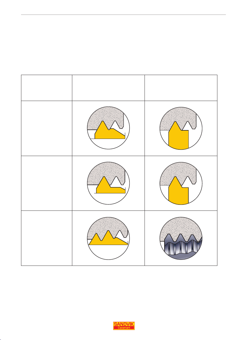
Insert types
Three main types of threading principle can be used to produce a
thread. The different technical and economic arguments for each
insert are the main guide in the choice of application.
Thread turning Thread milling
Full pro le
. Application
V-pro le
Multi-point
11
Page 12

. Application
s
Full pro le inserts – rst choice for high quality
thread forms
The most common insert type, used to form a complete thread
pro le, including the crest.
• Ensures correct depth, bottom and top pro le for a stronger thread
• Extra stock should be 0.03 – 0.07 mm (0.001 – 0.003”)
• No deburring required after threading operation
• Fewer passes required compared to a V-pro le insert, due
to the larger nose radius
• Separate insert required for each pitch and pro le
• Productive threading performance
Extra stock should be left on the workpiece for topping the nish
diameter of the thread.
Quality
Extra stock
V-pro le inserts – threading with minimum tool
inventory
These inserts do not top the thread crests. Therefore, the outer
diameter for screws and inner diameter for nuts must be turned to
the right diameter prior to threading.
• Same insert can be used for a range of pitches - provided
that the thread pro le angle (60° or 55°) is the same
• Fewer inserts needed in stock
• The nose radii is designed to offer the smallest pitch,
which reduces tool life
12
Flexibility
Page 13
s
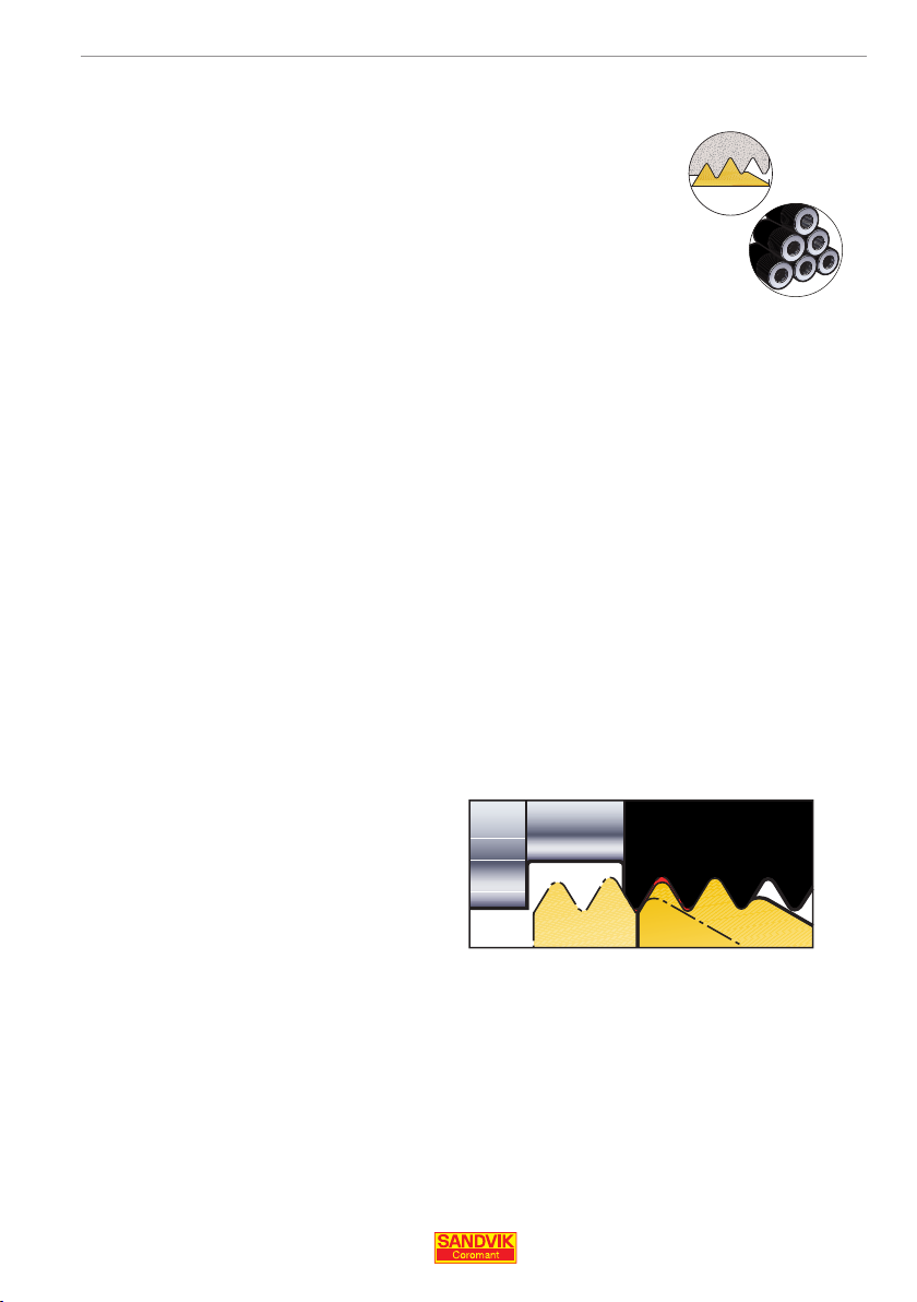
Multi-point inserts – productive, economic
threading in mass production
Multi-point inserts are similar to full pro le-, but have more than
one insert point (two pointed inserts give double productivity, three
pointed insert give triple etc.) Stable conditions are needed due to
increased cutting forces as the cutting edge has a longer contact
length.
Considerations should be made for thread turning and thread milling:
. Application
Milling
• Completes the thread in one revolution, when using solid carbide
thread mills.
Turning
• Requires fewer passes, giving better tool life, productivity and
lower tool costs.
• Requires longer passes beyond the workpiece thread to accomodate the extra points.
Thread turning with multi-point inserts
requires longer passes beyond the
workpiece.
Productivity
13
Page 14

. Applications – Thread turnin
g
Thread turning
Thread turning is the most common method of producing threads.
The many tooling systems offered by Sandvik Coromant cover
internal and external applications and make it possible to produce
threads of all sizes and pro les, across all segments of the
engineering industry.
Indexable-insert thread turning tools such as CoroThread 266 and
others offer high quality performance, providing dampening against
vibrations, security in small holes, and in the toughest materials.
14
Page 15

. Applications – Thread turnin
g
Insert geometries
Selecting the correct insert geometry is important in threading,
especially in machines where there is limited supervision. Here,
geometry A offers consistent tool life and quality and is the rst
choice for most applications, while geometry F is sharper, reducing
cutting forces.
The chip-forming geometry C enables more continuous and unsupervised machining, free from sudden stoppages. This results in
predictable tool life, and more active machining time.
First choice
Geometry A
First choice
• First choice for most operations and materials
• Rounded cutting edge for
safe and consistent tool
life
• Good edge security
Geometry F
Sharp edge
• Sharp cutting edge
• Clean cuts in sticky or
work-hardening materials
• Low cutting forces and
good surface nish
• Reduced built-up edge
Geometry C
Chip-forming geometry
• Maximum chip control,
minimum supervision
required
• High security for all
threading, particularly
internal
• Optimized for low carbonand low-alloyed steels
• To be used with 1° modi ed ank infeed only
15
Page 16
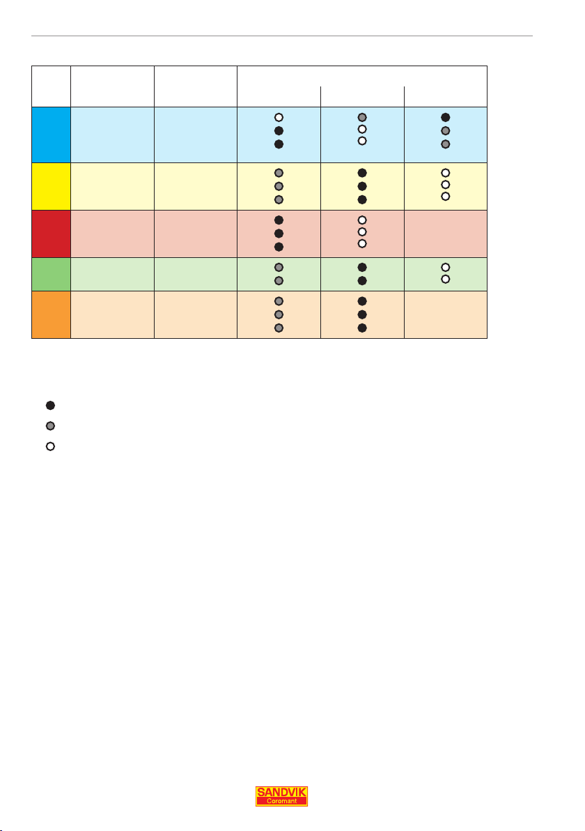
2. Applications – Thread turnin
g
Insert geometries
MC CMC Geometries
ISO No. No.
P1.1.Z.AN
P
P2.1.Z.AN
P2.5.Z.HT
P3.1.Z.HT
M5.0.Z.AN
M
M1.0.Z.AQ
M3.1.Z.AQ
K1.1.C.NS
K
K2.2.C.UT
K3.1.C.UT
N1.2.Z.UT
N
N3.2.C.UT
S1.0.U.AN
S
S2.0.Z.AG
S4.2.Z.AN
For ISO-H use CBN-insert, CB7015
First choice
Second choice
Alternative choice
01.1
02.1
02.2
03.21
05.11
05.21
05.51
07.2
08.2
09.1
30.11
33.2
20.11
20.22
23.21
AFC
16
Page 17
. Applications – Thread turnin
g
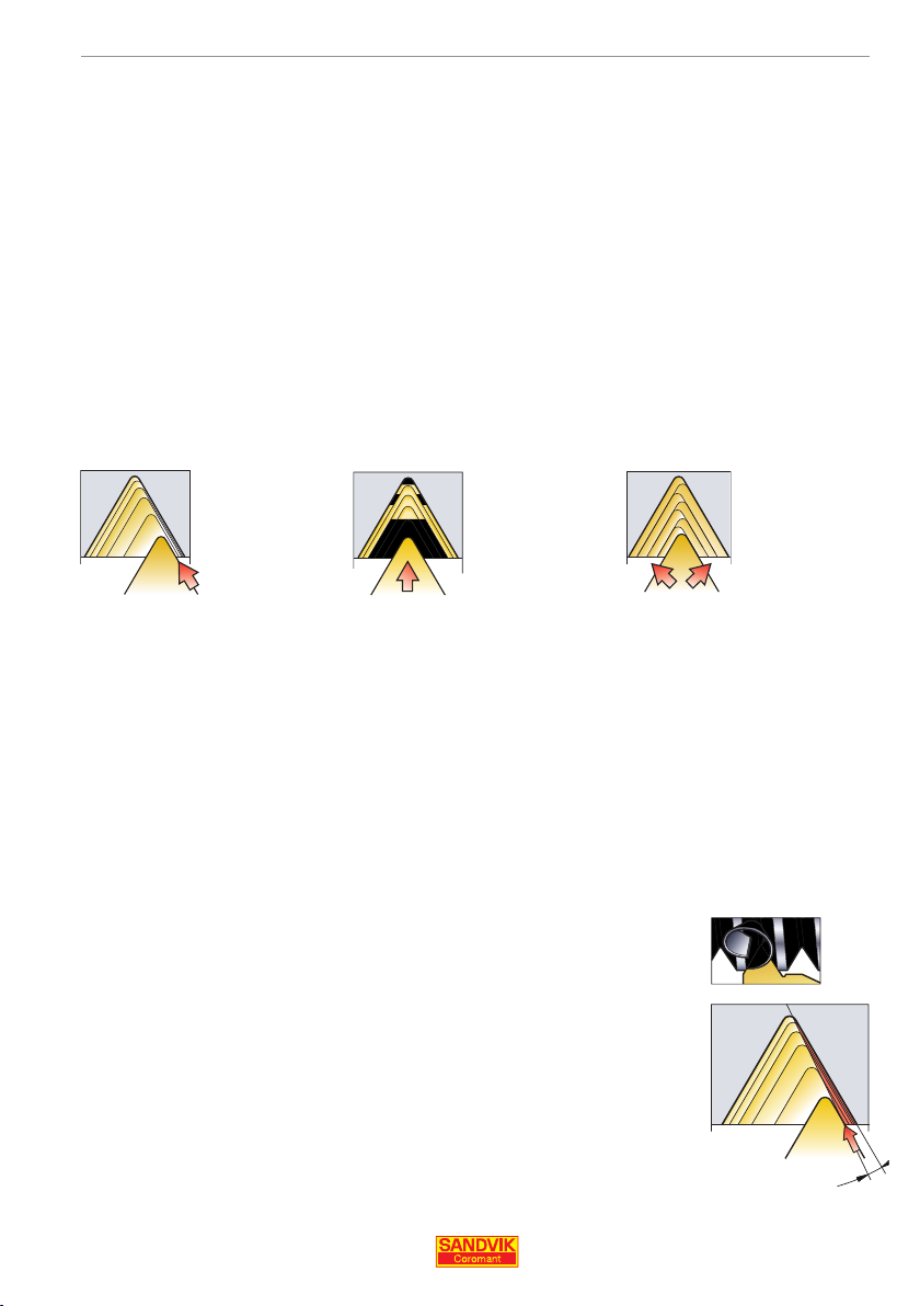
Infeed
Infeed method dictates how the insert is applied to the workpiece
to create the thread form. The three common infeed choices are
modi ed- ank-, radial-, and incremental infeed.
The infeed method used in threading will directly in uence:
• Chip control
• Thread quality
• Insert wear
• Tool life
Modi ed ank infeed Radial infeed Incremental infeed
Modi ed ank infeed
Has many advantages over radial infeed, and most CNC machines
are pre-programmed for this method which is modi ed (angled)
slightly to avoid the insert edge rubbing on the component surface.
• Recommended for all operations and insert types
• Chip is easier to form or guide, compared to radial infeed
• Chip is thicker but generated only on one side of the insert, making it easier to cut
• Fewer passes than for radial infeed, as less heat is transferred to
the insert
• Can be used on both anks of the thread (opposite anking) to
steer the chip in best direction
• For larger threads, and to eliminate vibration problems
• Use 3-5° infeed angle for A- and F-geometries
• An infeed angle of 1° should be used for C-geometry.
17
Page 18
2. Applications – Thread turnin
g
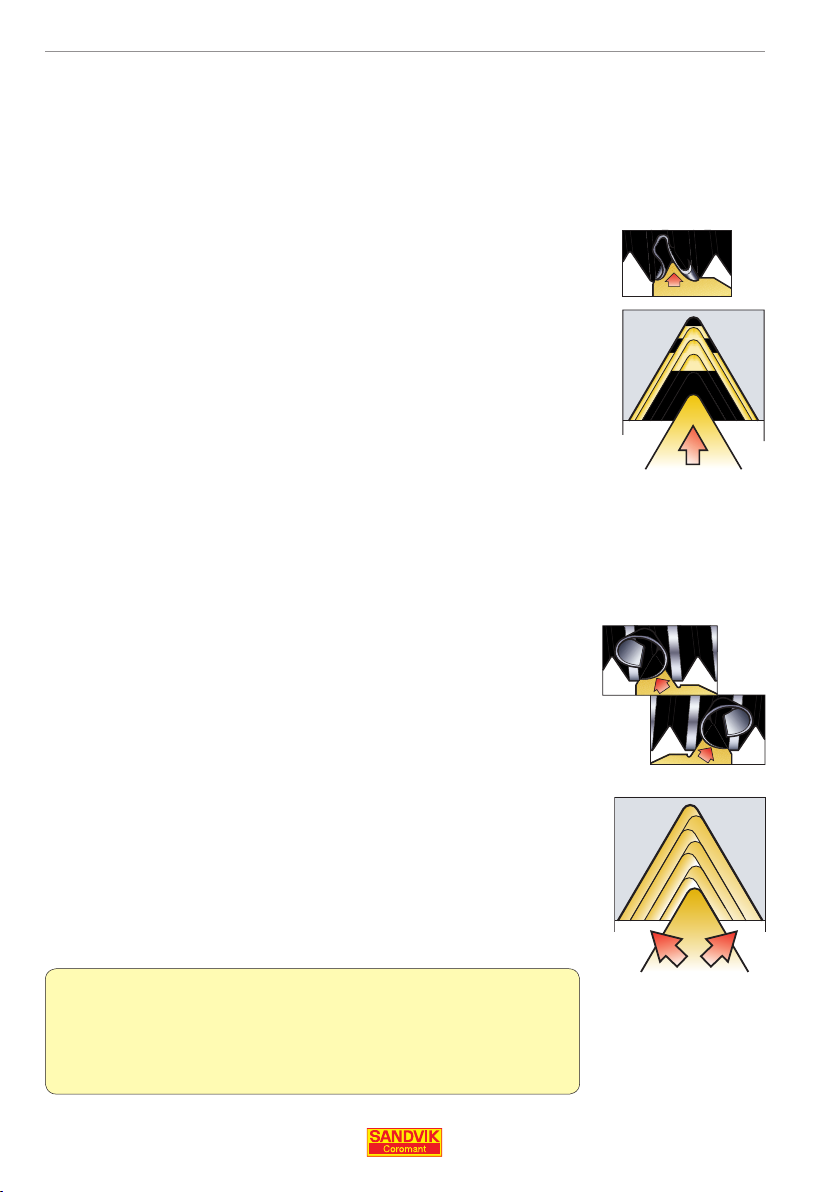
Radial infeed
The most commonly-used infeed method and the only one possible
on many non-CNC lathes.
• Produces a stiff, V-shaped chip, which is dif cult to form
• Insert wear is even on both anks
• Suitable for ne pitches
• Insert tip is exposed to high temperatures, restricting the
possible infeed depth
• Risk of vibration and poor chip control in large pitches
Incremental infeed - for pitches larger than 5 mm (5 t.p.i.)
This infeed type is the rst choice for larger thread pro les.
• Even insert wear and long tool life
• A- and F-geometries should be used
• Special CNC machine programme is required
Very large thread pro les can be pre-machined with a turning
tool, nishing passes can be made with the threading tool
For more information see page 33 (Threading large pro les).
18
Page 19
. Applications – Thread turnin
g
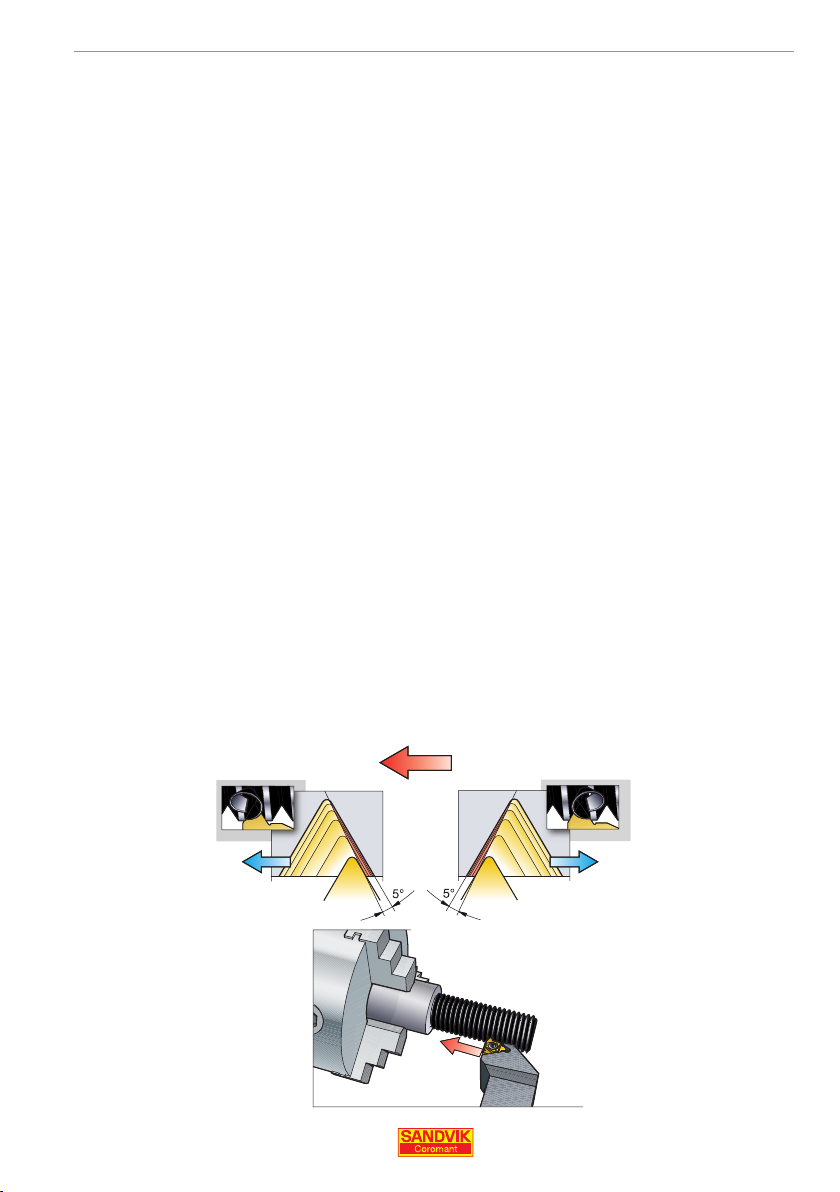
Successful chip control in thread turning
Threading can present problems in machines where there is limited
supervision. Chips can get trapped in chucks, often resulting in tool
damage and lost machining time.
To avoid these problems and achieve the best possible chip control,
use modi ed- ank infeed, together with a C-geometry (chip-control)
insert.
Opposite ank infeed
With this infeed type, the insert can cut using both anks (opposite
anking) meaning that the chip can be steered in the right direction.
This helps to ensure continuous, trouble-free machining, free from
unplanned stoppages.
Standard modi ed
ank infeed
Feed
direction
Chip direction Chip direction
Opposite
ank infeed
19
Page 20

2. Applications – Thread turnin
g
Infeed depths per pass
Decreasing depth per pass (constant chip area)
• First choice, most common
• First pass is deepest
• More ‘balanced’ chip area
• Even load on insert
• Last pass 0.07 mm (.003 inch)
Constant depth per pass
• Each pass is of equal depth, regardless of number of passes
• More demanding on the insert
• Can improve chip control
• Increases the required number of passes
• Should not be used for pitches larger than 1.5 mm or 16 t.p.i.
• A less-productive method
First choice
Normal CNC lathes are equipped with dedicated threading cycles,
where pitch, thread depth and number of passes can be set in different ways – including the rst and last passes.
For the last pass, we strongly recommend against using a spring
pass (a cut without radial cutting depth). It is more bene cial to use
the recommended infeed cycles to ensure better thread quality and
longer insert tool life.
20
Page 21

. Applications – Thread turnin
g
Number of passes and size of infeed per pass
The recommended depths of cut for the different passes are shown
in the table below.
• These are recommended as starting values - the most suitable
number of passes must be determined by trial and error.
• Infeeds of less than 0.05 mm (0.002 inch) should be avoided
• For Cubic Boron Nitride-tipped inserts, infeed should not exceed
0.10-0.12 mm (.004-.005 inch)
• For multi-point inserts, it is essential that the correct infeed recommendations are used
Infeed value recommendations
Number of infeeds and total depth of thread.
For tables and recommendations see chapter 5, Technical reference (page 96) or use the Sandvik Coromant threading calculator
for more values.
21
Page 22
2. Applications – Thread turnin
g
Tool holder selection
The choice of tool holder used in a threading operation is in uenced by many factors:
• Component shape
• Tool availability
• Machine type and condition
• Chip control requirements
• Hand of thread
• Tool holder choice
Coromant Capto®
Quick change
coupling - for large,
internal threads
Boring bar - for
internal threading
coupling - for internal
and external threading
Drop head - for
external threading
QS shank tool - for external small part machining
in sliding head machines
22
Shank tool - for
external threading
Exchangable cutting
head - for internal and
external threading,
with anti-vibration
bars.
Page 23

. Applications – Thread turnin
g
External thread turning
This is the most common thread turning method. It is often easier
and less demanding on the tool and there are a number of different
methods which can be used to achieve the desired results.
Upside-down tool holders
In many operations, it is bene cial to use a tool holder in an
upside-down position, to help remove chips more effectively.
Drop-head tool holders are specially developed for threading
upside-down and allow the correct centre height to be maintained,
without having to change the clamping in the turret.
Conventional tool holder
(right-hand)
Drop-head tool holder
(right-hand)
23
Page 24
2. Applications – Thread turnin
g
Internal thread turning
Internal threading is more demanding than external threading, due
to the increased need to evacuate chips effectively.
Chip evacuation, especially in blind holes, is helped by using lefthand tools for right-hand threads and vice versa (pull-threading).
However, this also creates the greatest risk of insert movement.
Modi ed ank infeed should always be used to generate a spiral
chip, which is easy to guide towards the entry of the bore
Boring bar selection also has a strong in uence on the effectiveness of internal threading. Three main bar types can be used for
internal threading, depending on the length of overhang and level of
stability required.
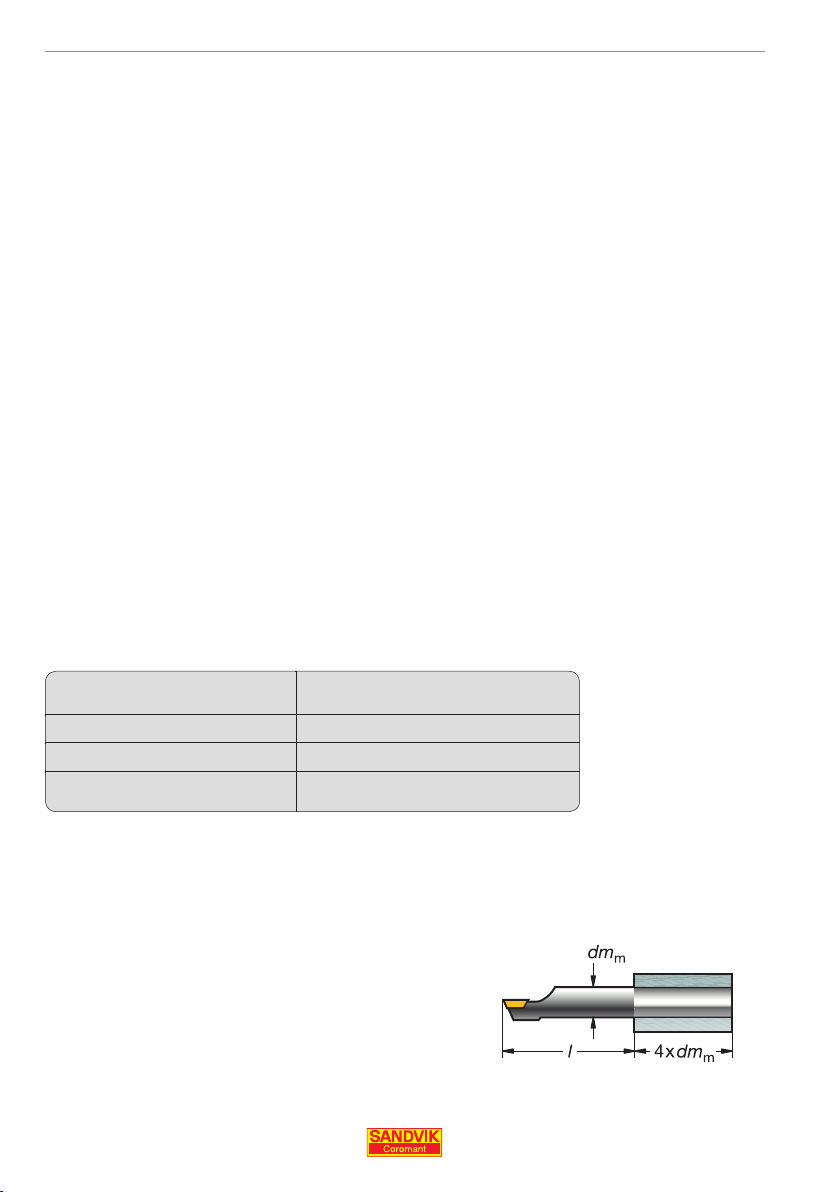
• Steel boring bars - maximum 2-3 x bore diameter overhang
• Steel dampened boring bars - maximum 5 x bore diameter overhang
• Carbide boring bars - maximum 5-7 x bore diameter overhang
Boring bar type Max. overhang
Steel
Steel dampened
Carbide
Boring bar de ection is in uenced by the boring bar material,
diameter, overhang and cutting forces. The recommended clamping
length in a boring bar holder with a sleeve is 4 x bar diameter dm
24
2-3 x dm
5 x dm
5-7 x dm
m
m
m
.
m
Page 25
g
External Internal
Right hand
threads
Most
common
Left hand
threads
Right hand
threads
. Applications – Thread turnin
Left hand
threads
Right hand
tool/insert
Right hand
tool/insert
Left hand
tool/insert
Left hand
tool/insert
Left hand
tool/insert
Right hand
tool/insert
A negative shim must be used.
Right hand
tool/insert
Most common
Right hand
tool/insert
Left hand
tool/insert
Left hand
tool/insert
Left hand
tool/insert
Left hand
tool/insert
Right hand
tool/insert
Right hand
tool/insert
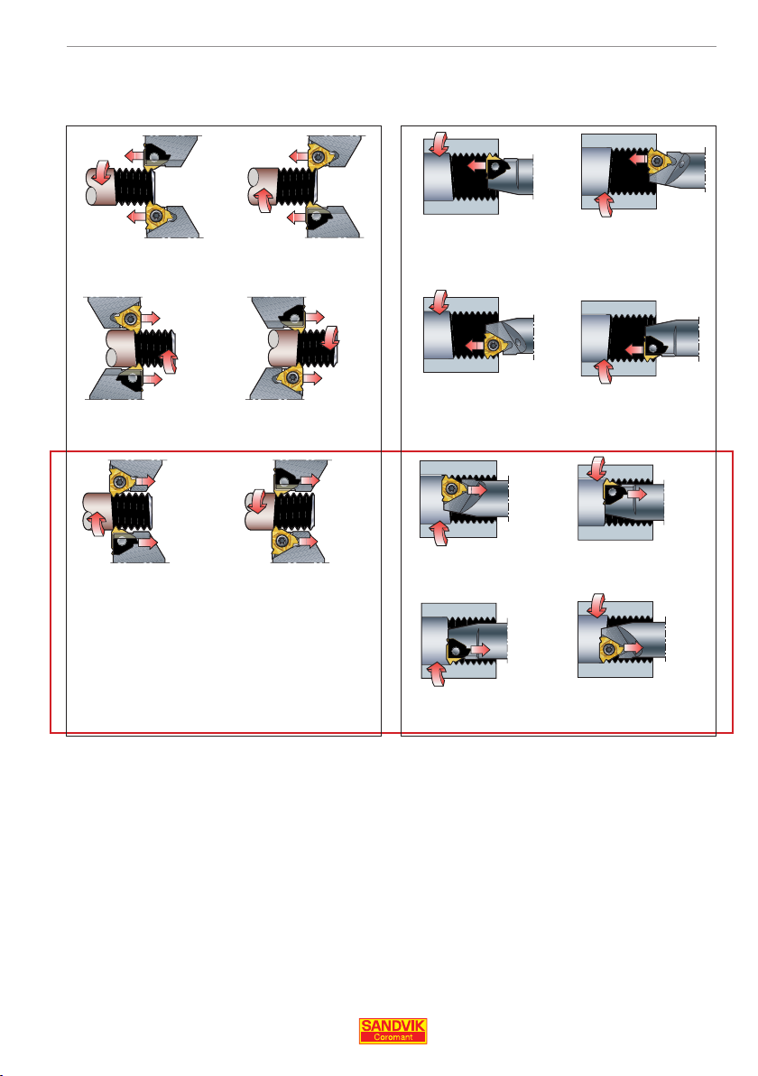
Thread turning methods
A thread can be produced in a number of ways. The spindle can rotate clockwise or
anticlockwise, with the tool fed towards or away from the chuck. The thread turning tool can
also be used in the normal- or upside-down position (the latter helps to remove chips).
Working away from the chuck
Using right-hand tools for left-hand threads (and vice-versa) enables cost savings through
tool inventory reduction (a negative shim must be used). Care must be taken due to the
risk of insert movement, particularly at the beginning of the thread.
25
Page 26
2. Applications – Thread turnin
g
Insert clearance angles
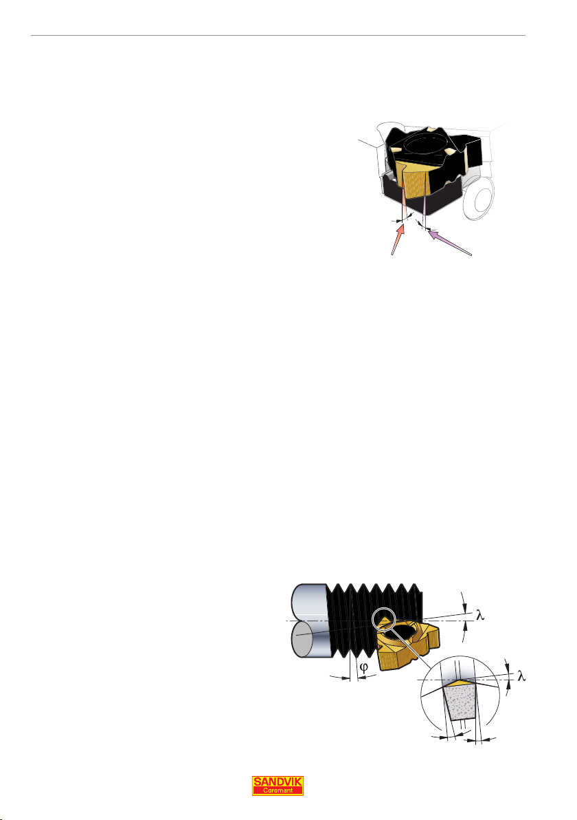
Two types of angular clearance between the insert and thread are
necessary for precise, accurate threading. These are:
• Flank clearance
• Radial clearance
Radial clearance
Flank clearance
Cutting edge clearance between the sides of the insert and thread
ank is essential to ensure that tool wear develops evenly, to give
consistent, high quality threads. The insert should therefore be
tilted to gain maximum symmetrical clearance from the anks ( ank
clearance angle).
The tilt angle of the insert should be the same as the helix of the
thread, to ensure success.
Flank clearance
26
Flank
clearance
Page 27
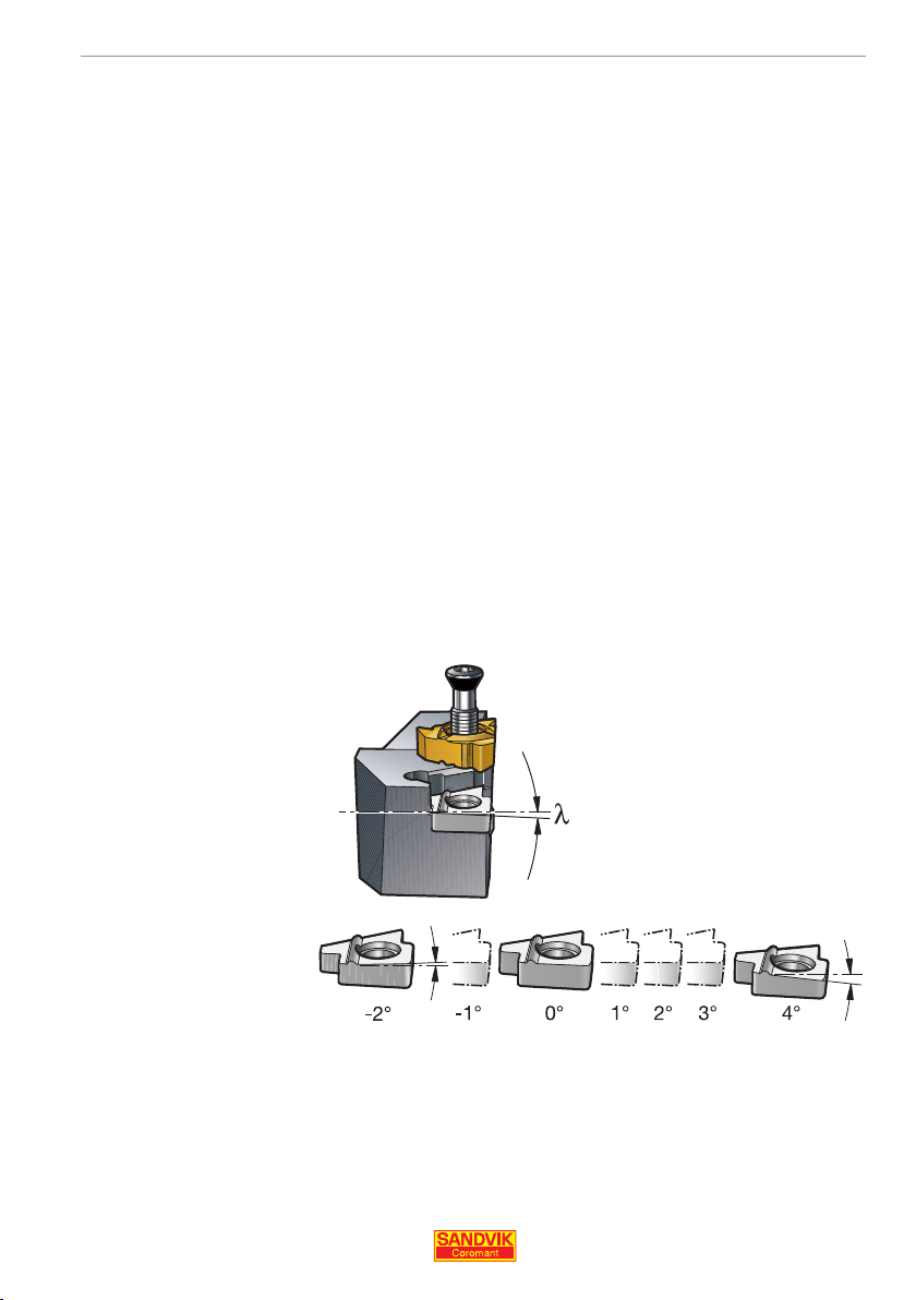
. Applications – Thread turnin
g
Selecting shims to tilt the insert for ank clearance
Insert shims are used to give different tilts to the insert, so that
the angle of insert inclination is the same as the helix of the
thread. See table opposite for methods of selecting the correct
insert shim.
• The standard shim in the holder is 1°, the most common angle of
inclination
• Shims are available in 1° steps, in the range -2° to 4°
• Negative-inclination shims are required when turning left-hand
threads with right-hand tools, and vice versa
= the angle of insert
inclination
The ank clearance angle of the insert is adjusted by changing
the shim under the insert in the tool holder. Standard tool holders have a 1° insert inclination angle.
27
Page 28
m
π
2. Applications – Thread turnin
g
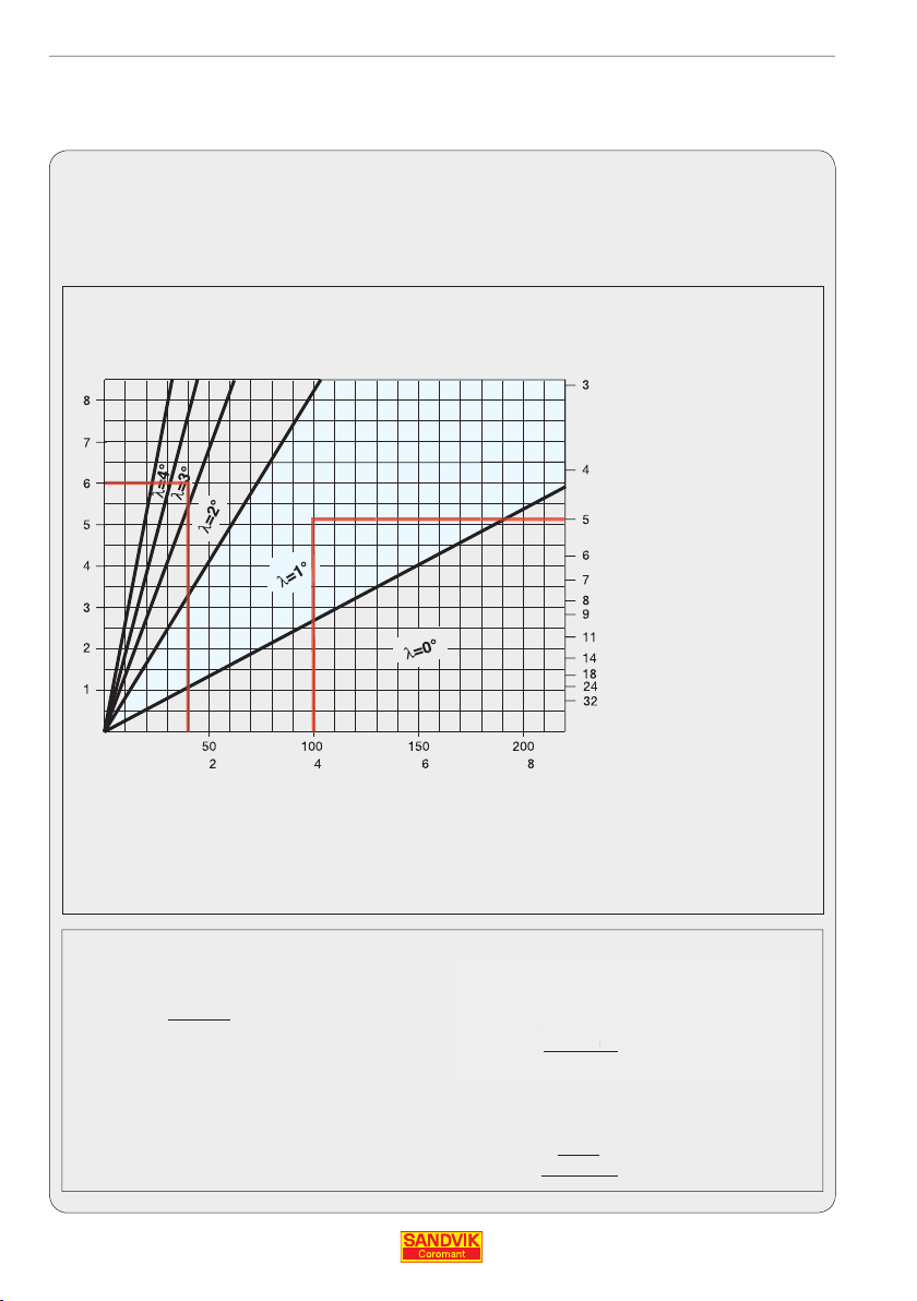
Methods for selecting the correct shim
Two alternative ways to select the correct shim:
A. Use the diagram, selecting shims.
B. Use the formula to calculate the helix angle to choose the corresponding shim.
Workpiece diameter and pitch in uence inclination angles
A.
Lead (Pitch) mm Threads/inch
Workpiece
diameter
For a pitch of 6 mm and a workpiece diameter of 40 mm, a 3° shim is
required. For a pitch of 5 threads per inch and a diameter of 4 inches, a
1° shim is required.
B.
P
=
tan
P
d
28
d2 x π
=
Pitch
=
Effective diameter of thread
2
=
P = 6 mm
d
= 40 mm
2
= arctan
P = 5 t.p.i.
= 4”
d
2
= arctan
mm
inch
6 mm
m
40 mm x π
mm x
1
5 t.p.i.
4” x π
= 2.7° use a 3° shim
= .91° use a 1° shim
Page 29
g
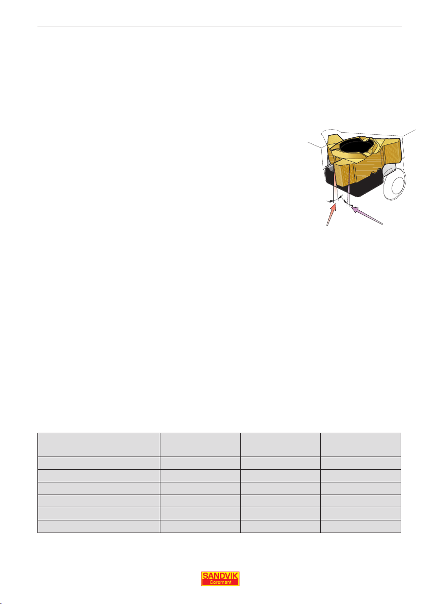
Relationship between ank clearance, radial clearance and
thread pro le angle
The smaller the thread pro le and radial clearance angles, the
smaller the ank clearance angle (see table below for ank clearance values when the correct shim, equal to the helix angle, is
used).
Please note that as the pro le angle becomes smaller, it is more
important to choose the correct shim.
. Applications – Thread turnin
Threads with small pro le angles
ACME, Stub ACME, trapezoidal and rounded threads fall into this
category and put extra pressure on the cutting edge. To minimize
this pressure, choose the correct shim to tilt the insert.
Thread
Pro le
Metric, UN
Whitworth
Trapezoidal
ACME
Buttress
Angle Internal 15° External 10°
( ()()
Flank clearance Flank clearance
60° 7.6° 5°
55° 7.1° 4.7°
30° 4° 2.6°
29° 3.8° 2.5°
10° / 3° 2.7° / 0.8° 1.8° / 0.5°
Radial
clearance ()
Flank
clearance
29
Page 30
2. Applications – Thread turnin
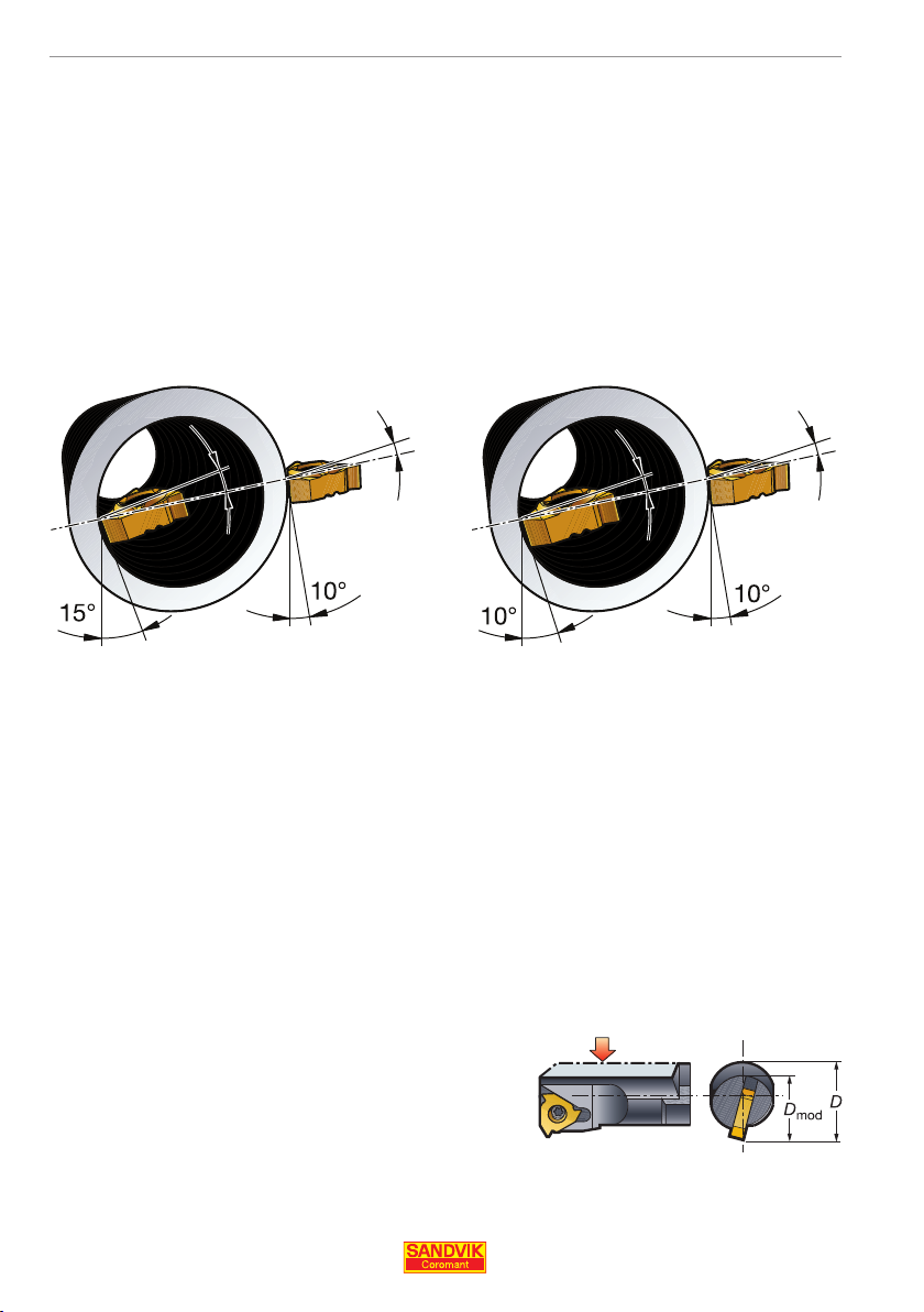
g
Radial clearance
To give adequate radial clearance, inserts are tilted in the tool
holder 10° or 15°.
It is important to use internal inserts with internal tool holders, and
vice-versa, to ensure that the correct thread form is achieved.
Insert sizes 11, 16 and 22 mm
Insert size 27 mm (5/8 inch)
(1/4, 3/8 and 1/2 inch)
Modi ed bars for small holes
Internal boring bars can be modi ed to t small holes and can be
used in place of special tools. These modi ed bars retain their
rigidity, as long as the recommended minimum dimension D
retained – see main catalogue for further information.
30
min
is
Page 31
. Applications – Thread turnin
g
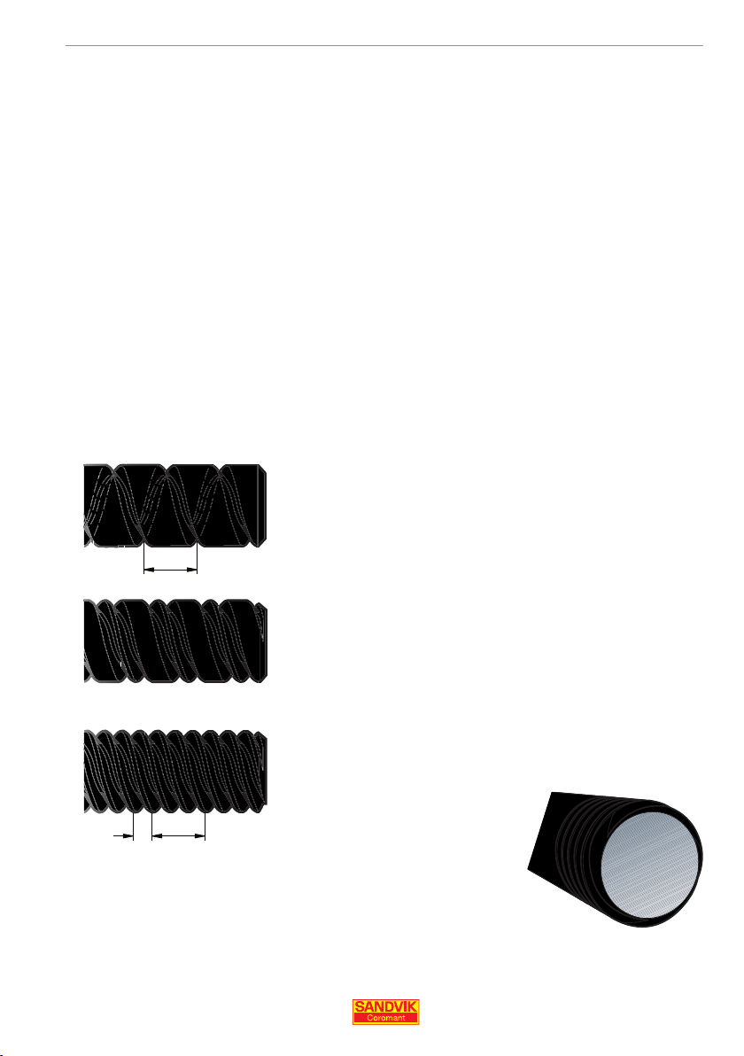
Multi-start threads
Threads with two or more parallel thread grooves require two or
more starts. The lead of this type of thread will then be twice that
of a single-start screw.
The lead increases relative to the pitch by a multiple equal to the
number of starts. On a single-start thread, the lead and the pitch
are equal; on a double start- the lead is twice the pitch, on a triple
start- the lead is three times the pitch etc.
To produce a multi-start thread, make a single thread groove with
a number of passes, followed by the second thread groove with a
number of passes, then the third thread groove with a number of
passes.
First threading groove
Lead
LeadPitch
Second threading groove
Third threading groove
A multi-start thread
with 3 starts
31
Page 32
2. Applications – Thread turnin
g
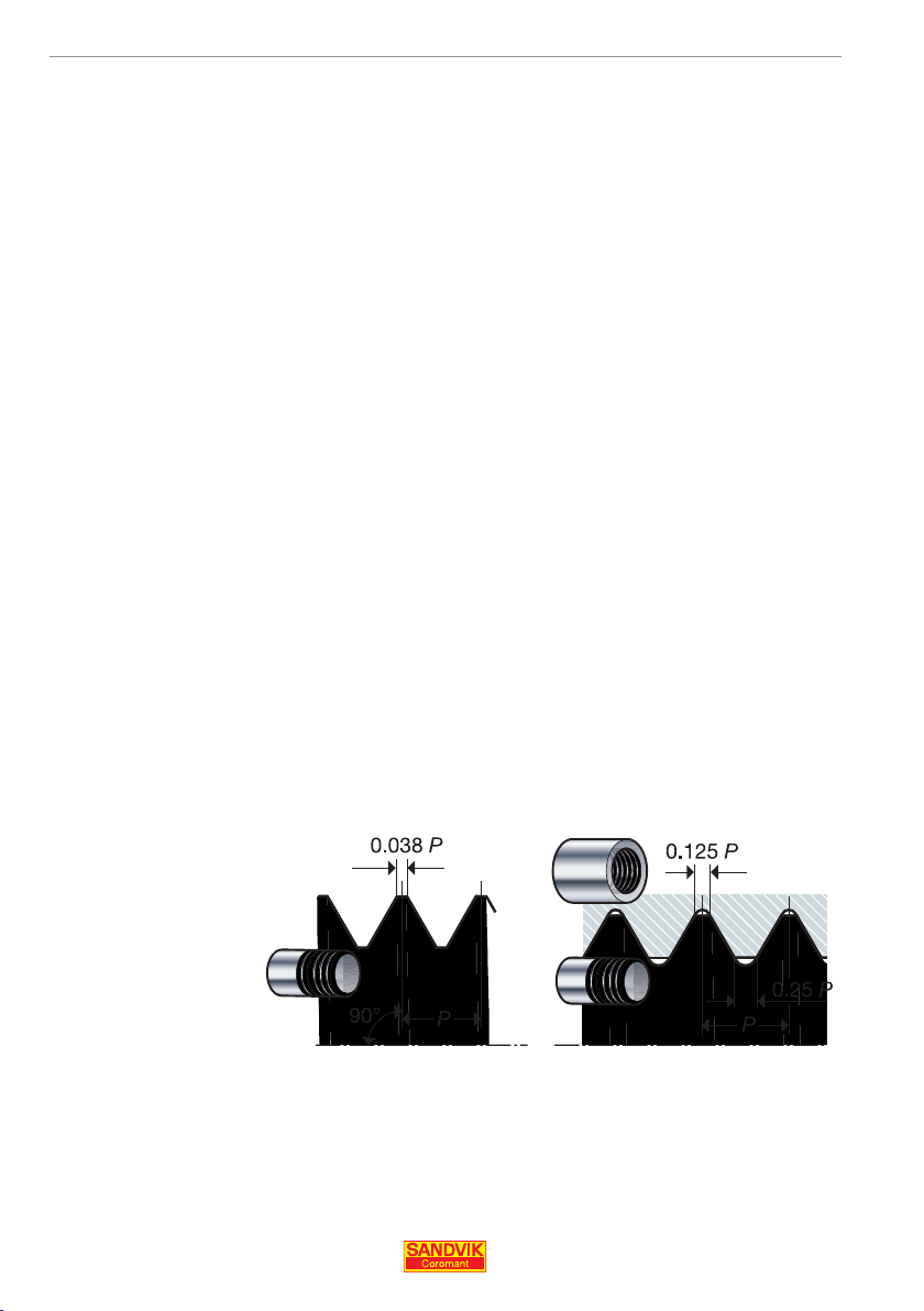
Insert nose radius and tool life
The nose radius is the smallest point on the insert and the most liable to break under the extreme pressure of a threading operation.
Nose radii differ considerably for different insert types and consideration should be made to the cutting speed and number of passes
in order to optimize performance and machining security.
NPT and NPTF inserts have the smallest nose radii within the
standard range. For optimized performance increase the number of
passes and reduce cutting speed.
The internal insert has a signi cantly smaller nose radius than the
external insert.
32
NPT/NPTF UN/MM
Page 33
g
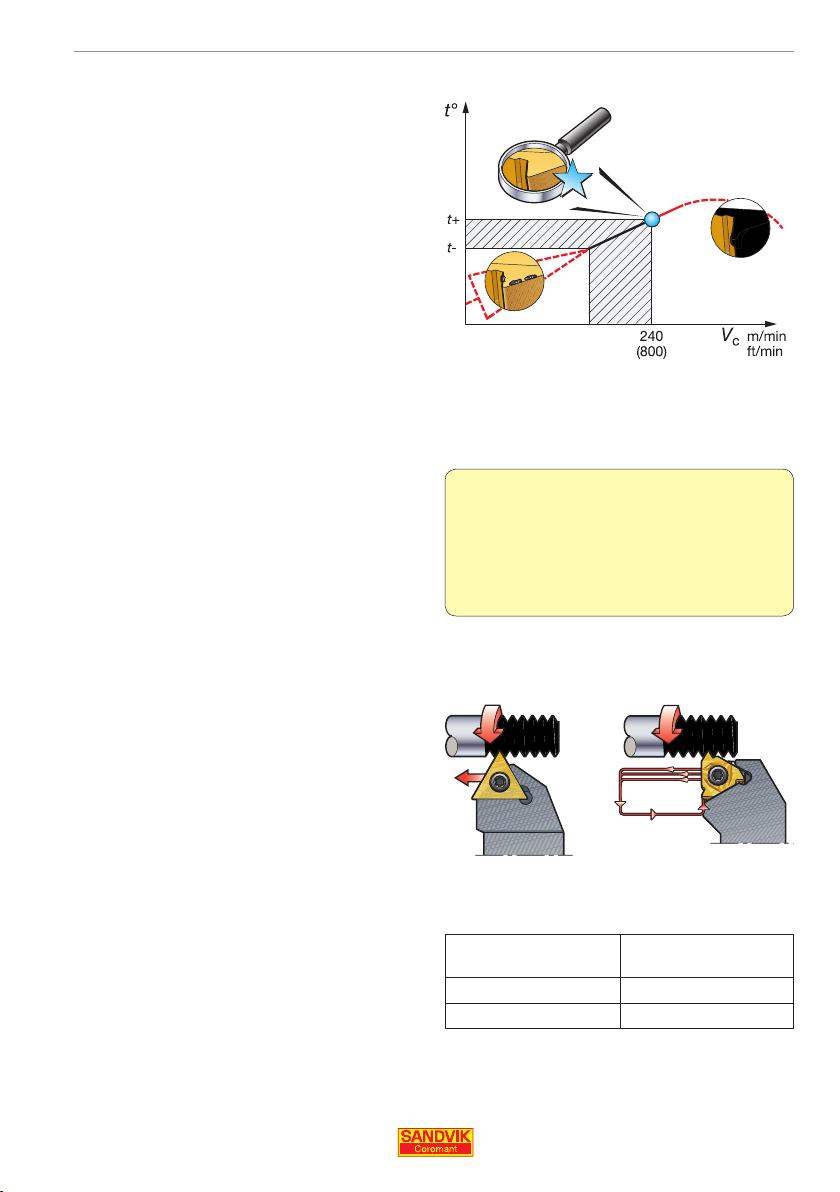
Insert tool life
Careful observation of the insert after
threading will allow you to achieve optimum
results regarding tool life, cutting speed and
thread quality. The main points to consider
are:
• When thread turning or thread milling at
low speed, the main problem is builtup edge. To solve this, increase cutting
speed
• When thread turning at high speed,
plastic deformation of the tip is the main
problem. To solve this, decrease cutting
speed
• When thread milling, the main problem
is terminal cracks on the insert. This can
be addressed by increasing the coolant
volume or reducing the cutting speed
. Applications – Thread turnin
For information on the causes and solutions to different forms of insert wear
see chapter 4, Troubleshooting (page
76).
Threading large pro les
When threading large pro les, it is advisable to use a conventional turning tool to
pre-machine the thread form before applying
the threading tool. This will extend the
life of the threading insert and give higher
thread quality.
When machining threads with small-radius
roots and crests, similar pre-machining can
also be applied by rough threading using
an insert with the same angle, but larger
nose radius. Allowance is then left for the
remaining nishing passes to be taken with
the right insert.
Pre-machining with CoroTurn 107
Pro les Recommended
60° MM, UN
55° WH
tool holder
STTCR/L
SDNCR/L, TR-D13NCN
33
Page 34
2. Applications – Thread turnin
g
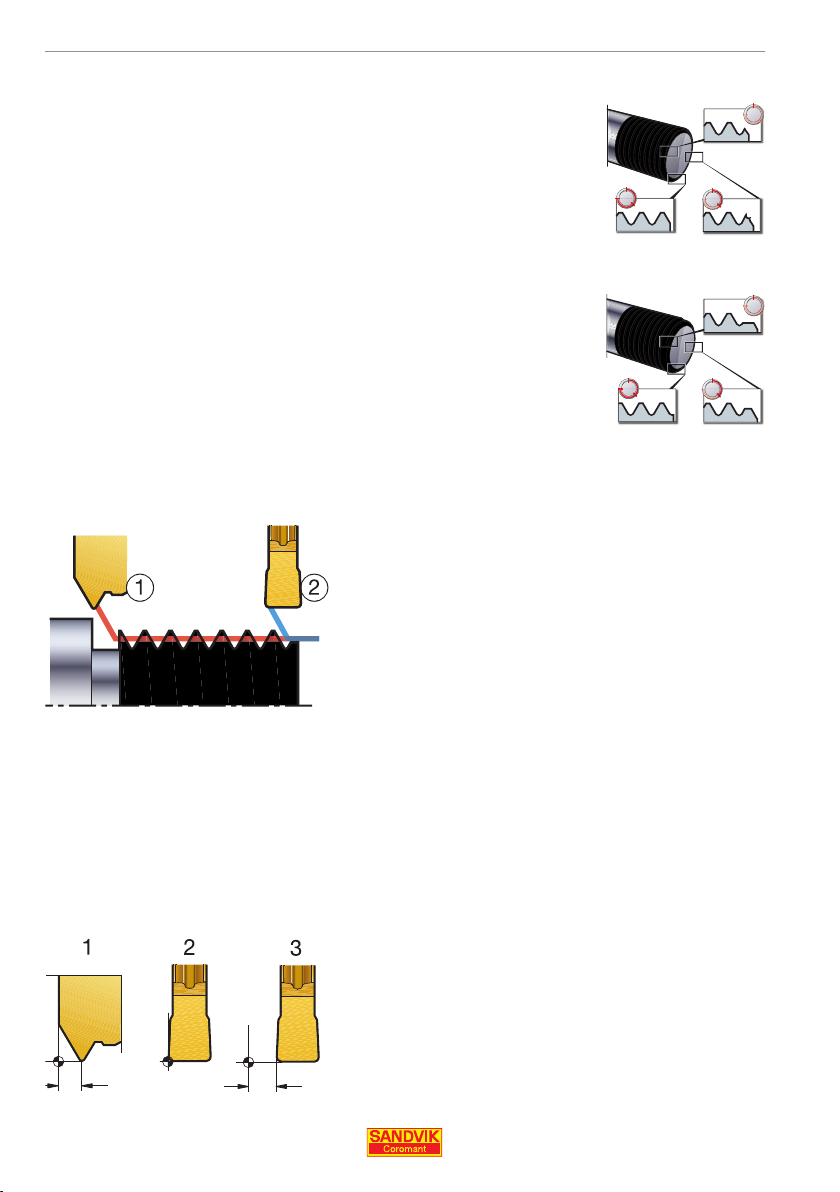
Thread deburring
Burrs which appear at the start of the thread can cause problems
and should be removed. This is especially important, for example,
in the hydraulics and food processing industry where tolerance and
quality demands are high.
Burrs tend to form at the start of a thread before the insert creates the full pro le, mostly in diff cult stainless steels and duplex
materials - thread deburring is achieved with standard turning tools
(mainly CoroCut inserts).
An important consideration is correct positioning of the deburring
insert in relation to the thread, pitch and thread cycle.
How to deburr a thread
1. Use a standard thread cycle with the recommended infeed data. The tool should enter the
thread at a 45° angle.
z z
34
2. Use the same thread program, with the same
cutting speed and a CoroCut insert, at half the
number of passes. Program the deburring length
to 1 x pitch, and measure the zero-point according to the images below.
Setting instructions
1. Set the zero point of the threading insert.
2. Measure the zero point on the CoroCut insert.
3. Offset the CoroCut insert with z (see main
catalogue).
Page 35

. Applications – Thread millin
g
Thread milling
Thread milling produces threads with the circular ramping movement of a rotating tool. Here, the lateral movement of the tool in
one revolution creates the thread pitch.
Although not as widely used as thread turning; thread milling
achieves high productivity in certain applications and offers an
advantageous alternative to thread tapping.
Thread milling should always be the application of choice
when:
• Machining asymmetric/non-rotating components
• Machining materials causing chip breaking and chip evacuation problems
• Machining tough materials creating high cutting forces
• Machining against a shoulder or close to the bottom of a blind hole
• Machining thin-walled components
• Component set-ups are unstable
• You need to minimize tool inventory
• You do not want to risk tap breakage on expensive parts – as thread mills can always be
removed from the component totally.
Thread milling requires a machine tool capable of simultaneous movement in the X, Y and
Z-axis direction.
35
Page 36
2. Applications – Thread millin
g
Bene ts of thread milling vs. tapping
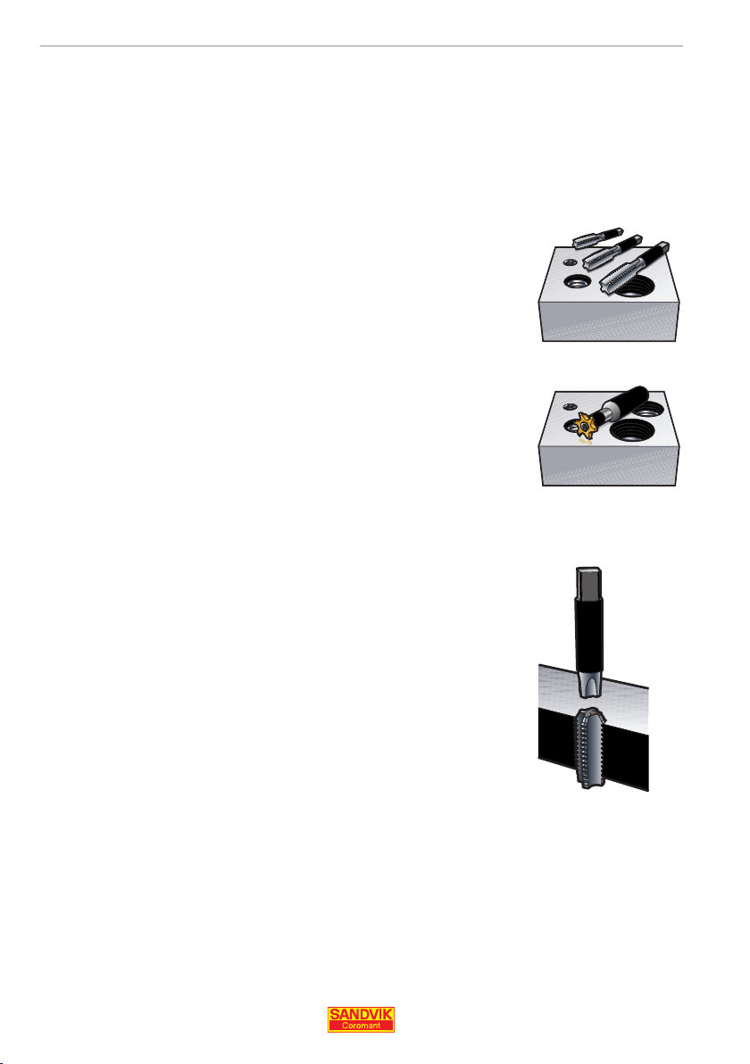
When deciding on the choice of threading method, the bene ts of
thread milling over thread tapping should be considered.
Tooling inventory
• Standard tool holders
• One thread mill tool covers different diameters
• Same thread milling insert for left- and right-hand threads
• Different pitches possible with one insert
Separate tap needed for
each hole
Tool breakage
• Easier to remove a broken tool from the component
• Maximum production security
• Reduced machine downtime
• Ideal for dif cult materials
• First choice for expensive components/last stage machining
Chip control
• Better chip control, fewer machining stoppages
• Bene cial method in long-chipping materials
One thread mill for all
holes
36
Page 37
g
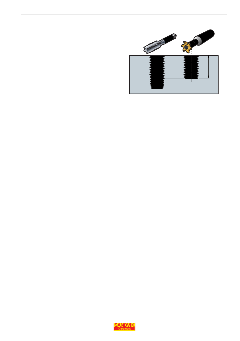
Thread quality
• Due to its shape, a thread mill can
achieve full-bottom threading in a blind
hole with no extra drill depth required
• A thread mill can be programmed with radius correction, allowwing for easy adjustment of the thread tolerance
• A thread mill minimizes the pre-machined hole diameter, compared to a tap, so that threads can be produced with better
thread coverage
. Applications – Thread millin
Coolant
• A thread mill does not require coolant
Cutting force
• A thread mill can make large threads in smaller machines due to
reduced cutting force
• Reduced cutting forces also make thread mills an ideal solution
for machining thin-walled components
37
Page 38

2. Applications – Thread millin
g
Thread milling – main considerations
To achieve the best results in a thread milling operation, always
consider the following points.
- Choice of cutting diameter
A smaller cutting diameter will help to achieve higher quality
threads.
- Tool path is important
• Tool path will give right or left hand threads, using down- or upmilling
• Always engage and retract the thread mill in a smooth path, i.e.
roll in and out of cut
- Be aware of feed per tooth
Always work with small feed per tooth values (very small hex) to
achieve best quality.
- Always calculate the correct feed required by the machine
software
To ensure the correct insert load.
- Several infeed passes may be needed
In dif cult applications, it may be necessary to separate the operation into several infeed passes to achieve higher quality threads.
- Dry machining is the rst choice
38
Page 39

. Applications – Thread millin
g
Choice of cutting diameter
The cutter engagement will create a minute form error on the root
of the thread pro le. In internal applications, the relationship between threading diameter, cutting diameter and pitch will affect the
true radial depth of cut, a
chosen radial depth of cut. A larger true ae will increase the deviation in the root of the thread.
To minimize the pro le deviation, the cutter diameter should be no
greater than 70% of the threading diameter.
eff, which becomes much larger than the
e
Ex M30x3
Dia 21.7 gives a pro le deviation of
0.07 mm (.0027 inch)
Dia 11.7 gives a pro le deviation of
0.01 mm (.0004 inch)
39
Page 40
2. Applications – Thread millin
g
Tool path
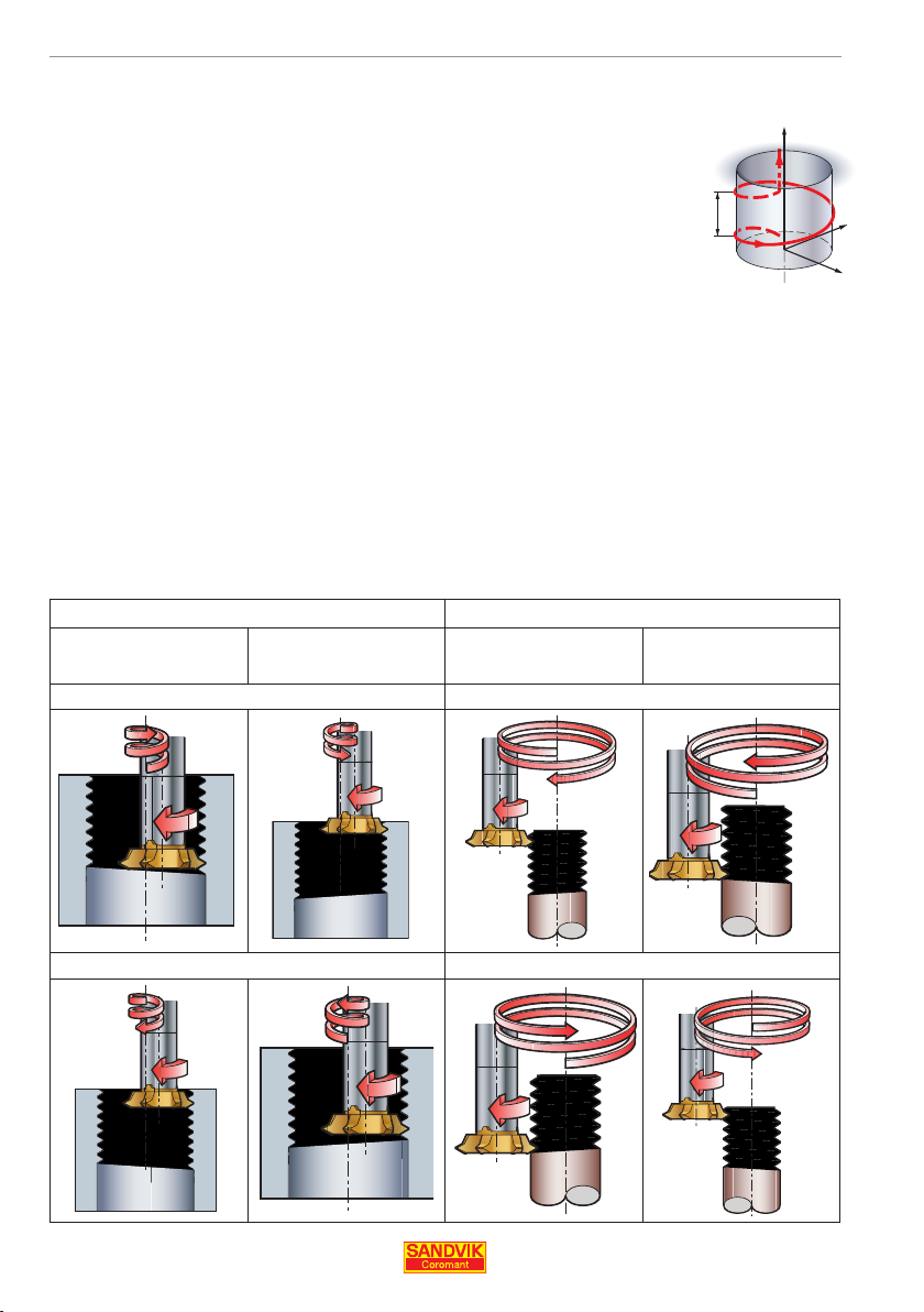
Thread milling requires machine tools which are capable of simultaneous movements on the X, Y and Z axes. The thread diameter is determined by the X and Y axis, while pitch is controlled by the Z axis.
Z
Right-hand internal threads
All cutters are initially positioned as close as possible to the bottom
of the hole, and then move anticlockwise in an upwards direction to
ensure that down milling is achieved.
Left-hand internal threads
Milling a left-hand thread follows in the opposite direction, from top to
bottom, also in an anticlockwise path to ensure that down milling is
achieved.
Internal External
Right-hand
threads
Down-milling Down-milling
Left-hand
threads
Right-hand
threads
First
choice
First
choice
Pitch
Left-hand
threads
Y
X
Up-milling Up-milling
40
Page 41
. Applications – Thread millin
g
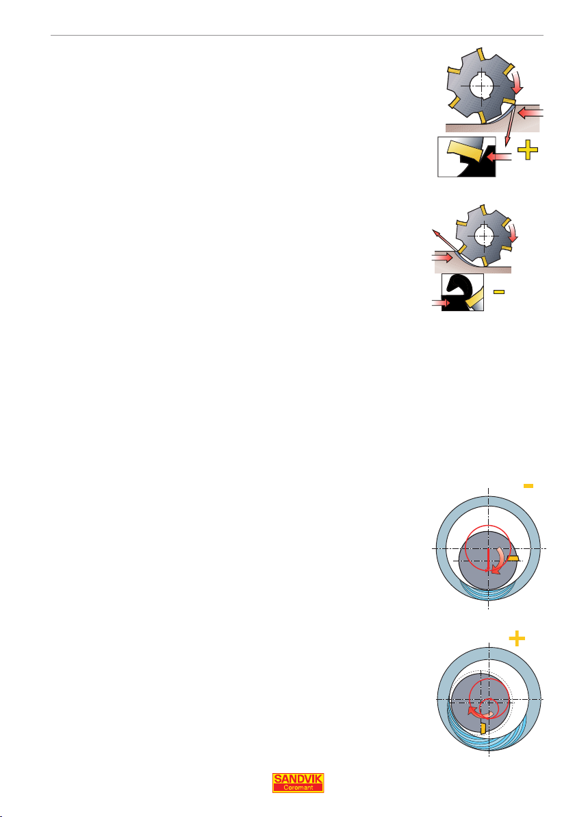
Down milling and up milling
Down milling is when the tool is fed in the direction of tool rotation
and is the preferred method of application - when machine tool,
xture and workpiece will allow. Chip thickness decreases from the
start of cut, until reaching zero at the end, which stops the edge
rubbing and burning against the surface before it is engaged into
cut.
In up milling, the feed direction of the cutting tool is opposite to its
rotation.
Entrance into cut – roll in
Make a soft entrance into the cut when circular milling or circular
ramping. This can be done by performing an extra circle, which
results in slow engagement into the material.
For each quarter revolution (90°) during the entrance into cut, the
pitch should be divided by four.
Smooth entrances into the cut are also essential to avoid vibration
and extend tool life.
41
Page 42
2. Applications – Thread millin
g
Feed per tooth
To avoid feed marks on the component surface, feed per tooth
should not exceed 0.15 mm/tooth (.006 inch/tooth), therefore a
small h
value is needed.
ex
Always calculate the correct feed required by
machine software
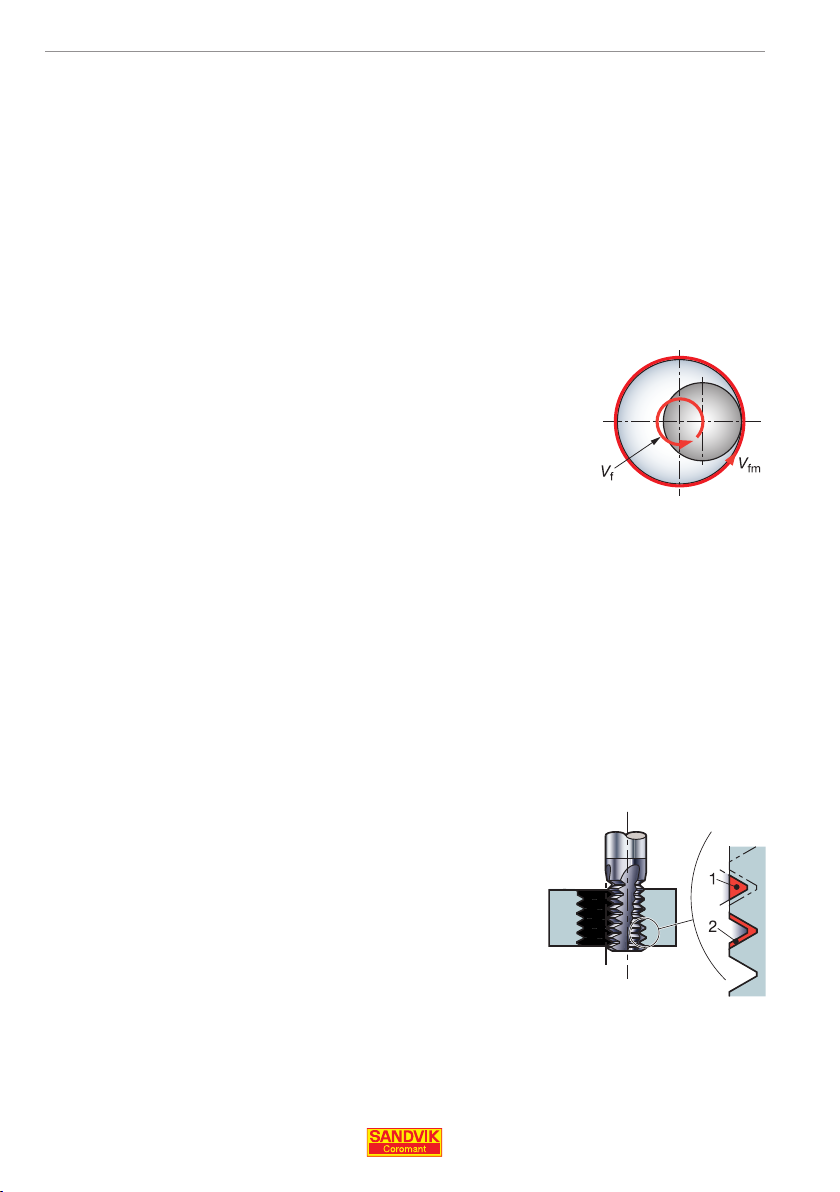
The feed value always depends on the hex value which corresponds
with the peripheral feed rate, however many machines require a tool
centre feed (v
In internal applications, the tool path of the periphery is faster than
the movement of the tool centre line. Feed rate programming on
most milling machines is based on the centre line of the spindle
and this must be included in thread milling calculations to maximize tool life and avoid vibration/tool breakdown.
For more formulas see chapter 5, Technical reference (page 117).
).
f
Machining with several infeed passes
Separating the thread milling operation into several infeed
passes achieves larger thread pitches and improves security
against tool breakage in dif cult materials.
Thread milling with several infeed passes also improves
thread tolerance, due to reduced tool de ection. This gives
greater security in long overhangs and unstable conditions.
42
Page 43

. Applications – Thread millin
g
Wet or dry machining
Machining dry is always recommended as cutting uid emphasizes
temperature variations at entry and exit, creating thermal cracks.
Cutting uid can be bene cial on certain occasions, such as when
nishing stainless steels/aluminium, machining HRSA or machining cast iron (to reduce toxic dust). However, it is most bene cial to
evacuate chips using compressed air.
Cutting data considerations
• In internal applications, ae is increased relative to straight cutting,
which reduces the chip thinning effect.
• In external applications, the radial depth becomes much smaller
and a higher cutting speed can be used.
• CoroMill® Plura cutters have a larger surface contact area than
end mills of equal length, and often a less favourable lengthto-diameter ratio. This can be compensated by reducing a
performing one or two extra passes.
• Conventional end mills and CoroMill Plura thread milling cutters
can use the same cutting speed.
• For CoroMill 327 and CoroMill 328, use the general recommendations for grooving and slotting.
• The entering angle for the nose radius is 90°. Since this is the
most sensitive part of the insert, h
calculations should be made
ex
using entering angle 90°.
and
e
For cutting data and values see chapter 5, Technical reference
(page 88) or use the Sandvik Coromant threading calculator/PluraGuide.
43
Page 44
2. Applications – Thread millin
g
External threading with milling tools.
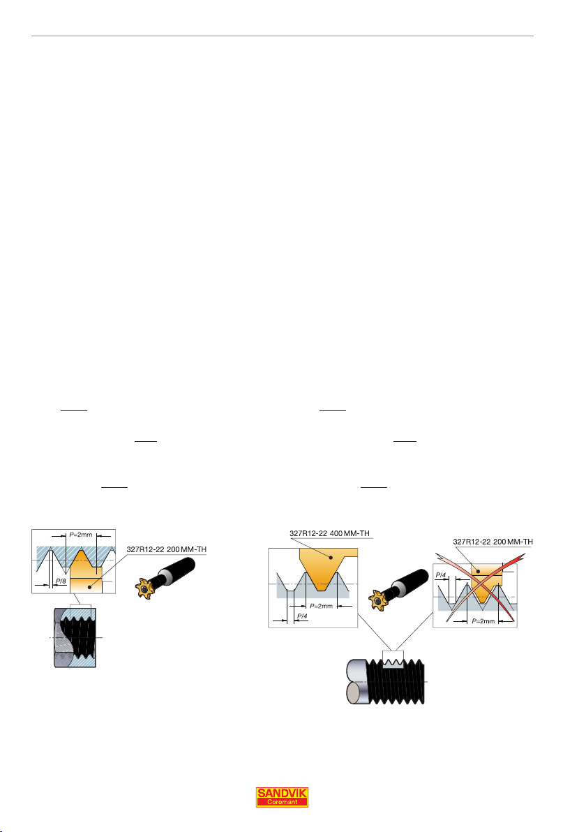
All thread milling inserts are designed for internal threads, however
CoroMill 327 and CoroMill 328 inserts can also be used for external
threading. Consider the size of insert nose radius for the two operations,
as a larger nose radius needs to be chosen for the external thread (internal
- pitch/8, external - pitch/4).
Thread root sizes differ slightly for internal and external threads. In the example below, a 2 mm (.078 inch) pitch insert, nose radius 0.25 mm (.0098
inch) ts a 2 mm (.078 inch) pitch internal thread, root 0.25 mm (.0098
inch). The corresponding external thread has a larger root, 0.50 mm (.019
inch) and therefore a 4 mm (.157 inch) pitch insert with larger nose radius
should be chosen to t this thread.
Internal thread
Pitch 2 mm
Height 1.08 mm
Root 0.25 mm
Insert 327R12-22 200MM-TH
Pitch 2
Max depth of cut 1.08 mm
Nose radius 0.25 mm
P = Pitch
For external thread milling recommendations see
chapter 5, Technical reference (page 112).
External thread
Pitch 2 mm
Height 1.08 mm
Root 0.50 mm
Insert 327R12-22 400MM-TH
Pitch 4
Max depth of cut 2.17 mm
Nose radius 0.50 mm
44
Page 45

Page 46
. Products - thread turnin
g
3. Products
Thread turning
The turning of threads is a common operation, with a wide range of systems available to
help achieve high standards of productivity and effectiveness. Thread turning tools can be
separated into two main areas - tools for external- and internal threading.
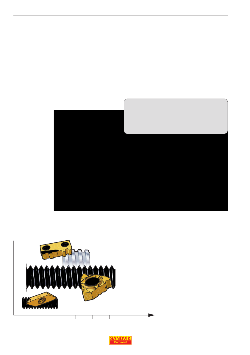
External thread turning
External systems:
CoroThread® 266
T-Max Twin-Lock®
CoroCut® XS
Thread
diameter
0.2
46
32
T-Max Twin-Lock®
CoroCut® XS
2.0
10 5 3
CoroThread® 266
8.0
mm
t.p.i.
Page 47
g
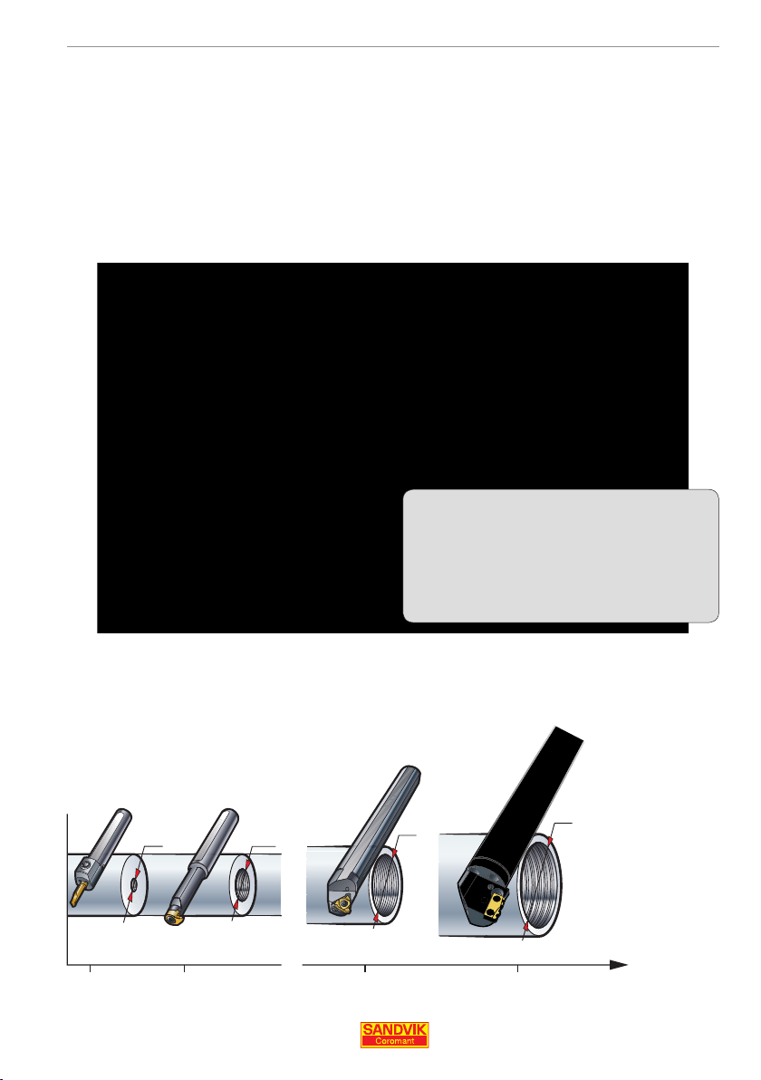
Internal thread turning
. Products - thread turnin
Internal systems:
CoroThread® 266
T-Max Twin-Lock®
CoroCut® MB
CoroTurn® XS
4
.157
≥ 4 mm
.157 inch
10
.393
T-Max Twin-Lock®
CoroThread® 266
CoroCut® MBCoroTurn® XS
≥ 10 mm
.393 inch
≥ 12 mm
.472 inch
≥ 60 mm
2.362 inch
Min. hole
diameter
12
.472
60
2.362
mm
inch
47
Page 48
. Products - thread turnin
g
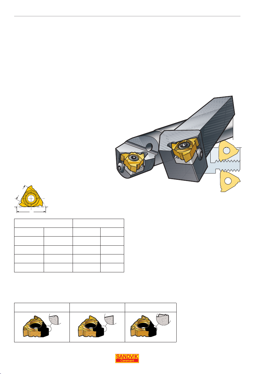
CoroThread® 266 – external and internal
threading
The rst choice, indexable insert threading tool. Inserts are located
on a guide rail on the shim, for high stability and precise, predictable machining.
• First choice system for all thread turning
• Large assortment of internal and external tools
• High stability
• Easy edge-indexing capability
• Easy insert mounting
• Reduced downtime
Insert sizes
iC
l
iC l
mm inch mm inch
6.350 1/4 11* .039*
9.525 3/8 16 .630
12.70 1/2 22 .866
15.875 5/8 27 1.063
*) No insert guide rail
Geometries
AFC
48
Page 49

g
The unique guide-rail interface between the insert and tip seat
eliminates insert movement caused by cutting force variation.
CoroThread 266 therefore provides accurate and repeatable thread
pro les as a result of rigid insert stability.
Insert with slots for rail guide
Shim with rail guide
The insert-rail support system solves the
problem of insert movement, which is often
caused by substantial forward- and reverse
cutting forces when entering and exiting the
thread.
. Products - thread turnin
The interface: holder - shim
The screw locks the insert securely in the
pocket, at the blue contact faces.
The interface: shim - insert
Cutting forces are distributed along the
back wall of the tool holder, indicated in red.
49
Page 50
. Products - thread turnin
g
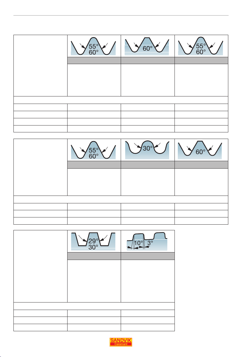
Assortment - CoroThread® 266
VW – VM MM – UN WH – NT
V-pro le 55° (VW)
Pitch: 28 – 4 t.p.i.
Metric 60° (MM)
Pitch: 0.5 – 6 mm
Whitworth 55° (WH)
Pitch: 28 – 4 t.p.i.
Type of insert
A (all-round)
F (sharp)
C (chip breaking)
Multi-point
Type of insert
A (all-round)
F (sharp)
C (chip breaking)
V-pro le 60° (VM)
Pitch: 1 – 6 mm
24 – 4 t.p.i.
UN 60° (UN)
Pitch: 32 – 4 t.p.i.
PT – NF RN MJ – NJ
BSPT 55° (PT)
Pitch: 28 – 8 t.p.i.
NPTF 60° (NF)
Pitch: 27 – 8 t.p.i.
Round 30° (RN)
Pitch: 10 – 4 t.p.i.
TR – AC – SA V – RD – BU
Trapezoidal 30° (TR)
Pitch: 1.5 – 8 mm
API 60°
Pitch: 5 – 4 t.p.i.
NPT 60° (NT)
Pitch: 27 – 8 t.p.i.
MJ 60° (MJ)
Pitch: 1.5 – 2 mm
UNJ 60° (NJ)
Pitch: 32 – 8 t.p.i.
Type of insert
A (all-round)
F (sharp)
C (chip breaking)
50
ACME 29° (AC)
Pitch: 16 – 3 t.p.i.
STUB-ACME 29° (SA)
Pitch: 16 – 3 t.p.i.
API Round 60° (RD)
Pitch: 10 – 8 t.p.i.
APT Buttress (BU)
Pitch: 5 t.p.i.
Page 51
g
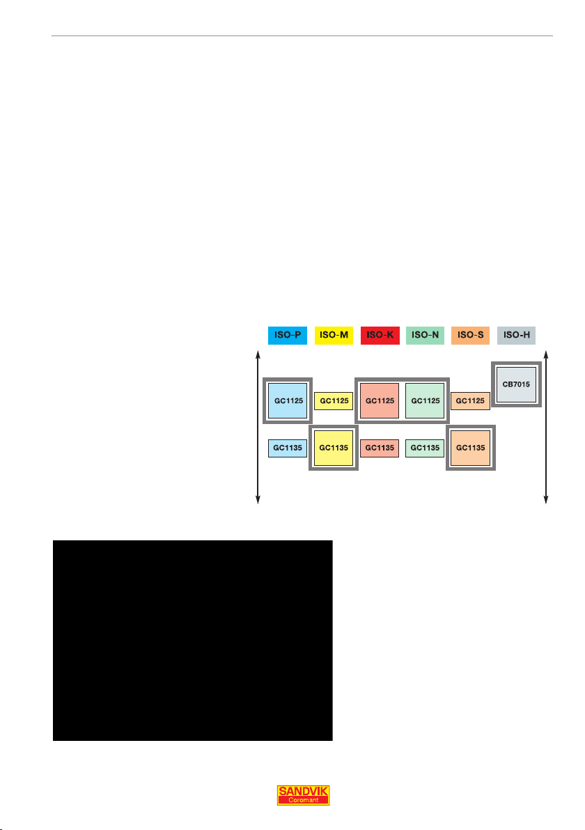
CoroThread® 266 – grade recommendations
Two unique grades offer the chance to boost threading performance
with CoroThread 266.
GC1125
Optimized for steel and cast-iron threading with high wear resistance. Can also be applied in ISO M, -N and -S materials
GC1135
Optimized for stainless steel and HRSA and the best choice for
sharp geometries, with high toughness and safe edges. Can also
be applied in ISO P and -K materials.
Stable conditions
. Products - thread turnin
Dif cult conditions
For cutting data information, refer to chapter 5, Technical reference (page 86) and for
infeed recommendations see chapter 5, Technical reference (page 96).
51
Page 52

. Products - thread turnin
g
CoroThread® 266 – tool holder assortment
The wide CoroThread 266 programme is available in the following
tool holder versions.
• Coromant Capto®, internal and external (C3 – C8)
• Shanks (up to 40x40 mm, 1½ inch)
• Bars (up to 50 mm, 2 inches)
• SL-cutting heads, internal and external (up to 40 mm, 1½ inch)
• SL-quick change, internal
• Shanks for small part machining (up to 16x16 mm, ¾ inch)
• Short holders for QS™ holding system (up to 16x16 mm, ¾ inch)
• Cartridges
52
Page 53

g
Tolerance classes with CoroThread® 266
CoroThread 266 turns threads in the following tolerance classes,
in metric, inch and Whitworth systems by concentrating only on the
pitch diameter.
Thread External/Internal Tolerance classes
ISO metric External
ISO metric Internal
ISO inch External
ISO inch Internal
Whitworth External
Whitworth Internal
6h – 6e
6H – 6G
2A
2B
A
—
. Products - thread turnin
Other tolerances available with CoroThread® 266
It is possible to turn threads to ner and courser tolerances with
CoroThread 266. However, additional measurements of external
major and pitch diameter, and internal minor and pitch-line diameters must then be made.
To accurately measure the pitch diameter, use a wire thread placed
in a normal micrometer. The most commonly used is a ‘stop and
go’ gauge which gives an accurate reading of the level of diameter
or pro le error.
53
Page 54

3. Products - thread turnin
g
Dampened 4C Silent Tools bars – vibration-free
internal threading
For internal threading operations - where radial forces are higher
than in external threading - the recommended bar type is 570-4C.
570-4C bars are developed primarily for internal threading applications. The combination of Silent Tools adaptor and ank infeed is
recommended for overhangs of up to 5 x D, to combat axial and
radial cutting forces.
• Unique dampening - reduces largest vibration
• Coromant Capto Coupling
• Flexible SL system
• Excellent surface nish
• Handles directional cutting forces
The 4C system is available as standard. The SL coupling at the
front end enables a large number of cutting tool combinations from
a small tool inventory, and is to be used primarily with CoroThread
266 cutting heads.
It is recommended to minimize the tool overhang and select the
largest possible tool diameter for best stability and accuracy.
54
Page 55

g
QS holding system for sliding head machines
– external threading
The QS holding system ts in the sliding head machine tool post
to provide a quick-changing alternative to conventional gang tool
racks. Tool holders are available for threading, turning and parting
and grooving.
• Saves time compared to conventional tool post systems
• Reduces tool indexing time from 3 minutes to 1 minute
• Exact tool position guaranteed with every set-up
The system of stops, wedges and short tool holders is compatible with Citizen, Star, Tsugami, Nexturn and Tornos sliding head
machines
Quicker tool changes and higher precision are the primary bene ts
of this system, which offers CoroThread size 16 inserts.
CoroThread 266 short holders with size 16 inserts are available in
size 10, 12, and 16 shanks (3/8, 1/2 and 5/8 inch).
. Products - thread turnin
55
Page 56
3. Products - thread turnin
g
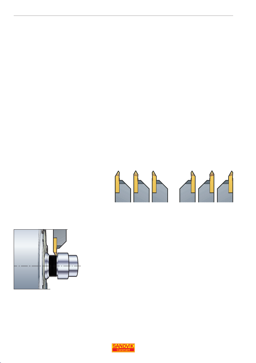
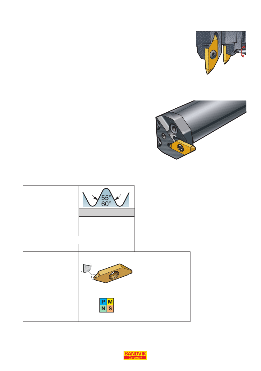
CoroCut®XS – external threading
For precision threading in small part machining, up to 32 mm (1.26
inch) diameter. CoroCut XS is used ideally where the tool is close to
the shoulder of the workpiece and in sliding head machines. Also
for parting, grooving and turning.
• All inserts t into the same tool holder
• Easy indexing and good accessibility when changing inserts
• Sharp cutting edges
• Low cutting forces
All inserts t into CoroCut XS shank
holders. Three types of insert: C, N
and A.
MATR right-hand
cutting insert/tool
holder.
-C -C-N -N-A -A
With insert types A and C, threads can be machined
very close to the component.
MATL left-hand
cutting insert/tool
holder.
C = Left hand
N = Neutral
A = Right hand
56
Page 57
g
Tool holder recommendations
All inserts t into the same tool holder and also with CoroTurn SL
cutting heads.
Good accessibility is achieved when changing inserts, as the insert
screw can be reached from both sides – to reduce downtime.
Assortment - CoroCut® XS
. Products - thread turnin
VM
V-pro le 60° (VM)
Pitch: 0.2 – 2 mm
12 – 80 t.p.i.
Type of insert
F-sharp
Geometry
Grade
For cutting data information, refer to chapter 5, Technical reference (page 86) and for
infeed recommendations see chapter 5, Technical reference (page 109).
F-sharp
ISO
GC1025
GC1105
H13A
57
Page 58

3. Products - thread turnin
g
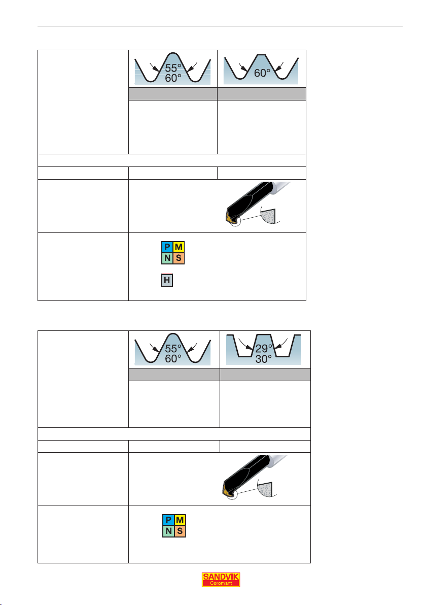
CoroTurn® XS – internal precision threading
CoroTurn XS has an insert in the form of a rod, mounted in an
easily-indexable adaptor. The tool is intended for precision machining in hole diameters from 0.3 – 12 mm (.012 – .412 inch), with
extremely sharp cutting edges giving good results at low feeds.
Threading inserts are available for UN, Whitworth, metric, TR and
NPT thread forms.
CBN inserts
CB7015
For cutting data information, refer to chapter 5, Technical reference (page 86) and for
infeed recommendations see chapter 5, Technical reference (page 110).
58
Page 59
g
Assortment - CoroTurn® XS
V-pro le 60° (VM)
Pitch: 0.5 – 1.5 mm
48 – 16 t.p.i.
Type of insert
F-sharp
Geometry
Grade
F-sharp
ISO
GC1025
. Products - thread turnin
VM MM – UN
Metric: 60° (MM)
Pitch: 0.5 – 2.0 mm
UN 60° (UN)
Pitch: 32 – 16 t.p.i.
(VM, MM-UN)
CB7015 (VM)
Type of insert
F-sharp
Geometry
Grade
WH – NT AC – SA
Whitworth 55°
Pitch: 28 – 19 t.p.i.
NPT 60° (NT)
Pitch: 27 – 18 t.p.i.
ACME 29° (AC)
Pitch: 1.5 – 3 mm
STUB-ACME 29° (SA)
Pitch: 16 – 8 t.p.i.
F-sharp
ISO
GC1025
59
Page 60
3. Products - thread turnin
g
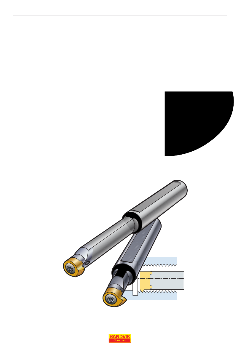
CoroCut® MB – internal threading
CoroCut MB has front-mounted exchangeable inserts for internal
machining in hole diameters from 10 – 25 mm (.394 – .984 inch).
Its sharp cutting edges give good results at low feeds.
Boring bars are available in steel and carbide, with through coolant.
The bars are to be used together with EasyFix clamping in up to 6
x bar diameter overhang.
• Sharp cutting edges
• Accurate clamping for correct orientation
• Round mounted exchangeable insert
• EasyFix for fewer vibrations and fast set-up
Assortment
Steel bars - for up to 3 x bar diameter overhang
Carbide bars - for up to 6 x bar diameter overhang
For cutting data information, refer to chapter 5, Technical reference (page 86) and for
infeed recommendations see chapter 5, Technical reference (page 111).
60
Page 61
g
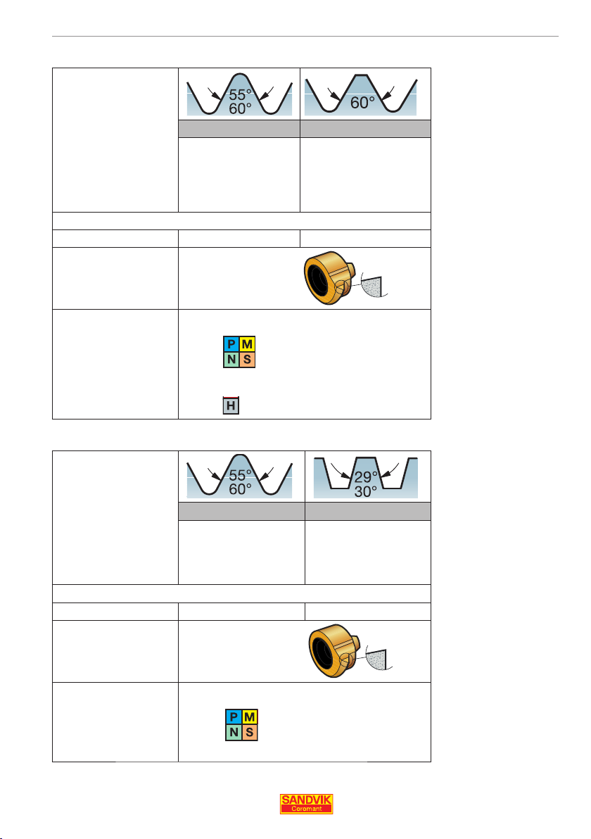
Assortment - CoroCut® MB
V-pro le 60° (VM)
Pitch: 0.5 – 2.5 mm
32 – 10 t.p.i.
Type of insert
F (sharp)
Geometry
F-geometry
. Products - thread turnin
VM MM – UN
Metric: 60° (MM)
Pitch: 0.5 – 2.5 mm
UN 60° (UN)
Pitch: 18 – 14 t.p.i.
Grade
Type of insert
F (sharp)
Geometry
Grade
ISO
GC1025 (VM, MM-UN)
CB7015 (MM)
WH – NT AC – SA
Whitworth 55°
Pitch: 19 – 11 t.p.i.
NPT 60° (NT)
Pitch: 18 – 14 t.p.i.
F-geometry
ISO
ACME 29° (AC)
Pitch: 16 – 8 t.p.i.
STUB-ACME 29° (SA)
Pitch: 16 – 8 t.p.i.
GC1025
61
Page 62
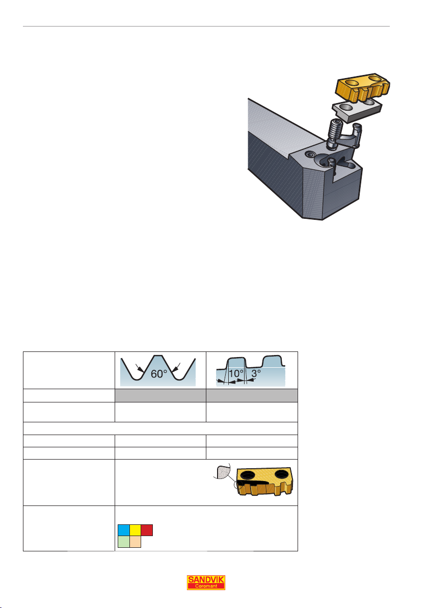
3. Products - thread turnin
g
T-Max Twin-Lock® – internal and external
threading
Designed for threading in high volume areas of the oil
and gas industry. Examples of applications are tubing,
casing and coupling production.
The system also covers connection threads,
where indexing accuracy, insert edge reliability
and repeatability are essential.
• Productive threading with multi-tooth inserts
• Minimum hole diameter 60 mm (.2.36 inch)
• ISO-M, -S, -P, -K, -N materials
• Optimized for steel
Tool holders
• SL-cutting head 40 mm
• Shank tool 32x32 mm
• Cartridge
Inserts
• API Round 10 – 8 t.p.i.
• API Buttress 3/4 – 1 i.p.f.
Assortment - T-Max Twin-Lock®
RD V – RD – BU
API 60° (RD)
Pitch: 10 – 8 t.p.i.
API Buttress (BU)
Pitch: 5 t.p.i.
Type of insert
A (all-round)
No. of points
Geometry
Grade
All-round
ISO
3 or 4
GC1125
2
PMK
NS
For cutting data recommendations see chapter 5, Technical reference (page 86).
62
Page 63
g
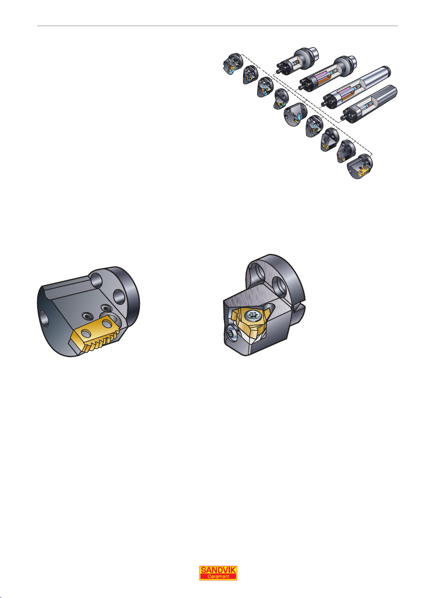
CoroTurn® SL cutting heads –
internal and external threading
SL (serration lock) exchangeable cutting heads enable a versatile
range of cutting units to be built from a manageable inventory. The
tools can be attached to a CoroTurn SL boring bar or adaptor to
provide added tooling exibility, with performace similar to a solid
tool regarding de ection and vibration.
For threading, exchangeable cutting heads are available for
CoroThread® 266 and T-Max® Twin Lock.
. Products - thread turnin
T-Max Twin Lock® CoroThread® 266
Choice of bar
The CoroTurn SL assortment includes:
• Coromant Capto and conventional shank design
• Solid steel bars and dampened Silent Tools
• Through coolant with every bar type
Vibration energy is absorbed by the tool bar making productive
cutting data possible.
63
Page 64

. Products - thread turnin
g
Extended offer
Due to the wide range of thread styles with different shapes and
pitches, Sandvik Coromant have prepared special insert types for
CoroThread 266, outside the standard range. These inserts ensure
high thread quality, productivity and exibility and are available for
the following thread designations:
CoroThread 266 threading inserts
11 – 27 mm (1/4” – 5/8”)
General threading pro les:
• MJ, ISO5855
• UNJ, ISO3166 (internal)
• American Buttress, ANSI B1.9
Oil pipe threading
• Hughes H90
• Big Omega
Tailor Made
In the Tailor Made system, additional tool options are available for
your speci c requirements - in grades GC1125, GC1135 and H13A.
Simply provide us with information regarding ank angles, pro le
height and radius - to design your individual pro le. See below for
further information.
Taper anglesPro le options
12
Contact your local Sandvik Coromant representative for more details and a quotation.
64
Page 65
g
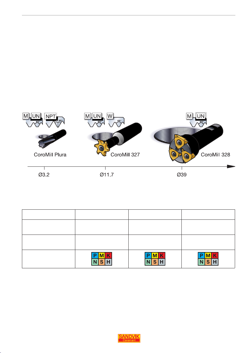
Thread Milling
The main options for thread milling using Sandvik Coromant tools
are single-point threading with CoroMill® 327 and CoroMill® 328,
and multi-point threading with CoroMill® Plura.
. Products - thread millin
CoroMill® Plura CoroMill® 327 CoroMill® 328
Pitch 0.7 – 3 mm
28 – 10 t.p.i.
Cutter dia (D
(inch)
ISO
• CoroMill 327 and CoroMill 328 are rst choice for large threads
and dif cult materials
• CoroMill Plura is rst choice for smaller threads and easier
materials
), mm
c
3.2 – 19
(.189 – .783)
1 – 4.5 mm
24 – 5 t.p.i.
11.7 – 21.7
(.461 – .854)
1.5 – 6 mm
16 – 4 t.p.i.
39 – 80
(1.535 – 2.480)
65
Page 66

3. Products - thread millin
g
CoroMill® 327 and CoroMill® 328 –
Single-point threading
CoroMill tools offer many advantages for thread milling. For singlepoint threading, use CoroMill 327 and CoroMill 328.
These versatile tools have different diameters and pitches, and are
designed for non-rotating components:
• Same inserts (V-pro le) can be used for different pitches
• Low cutting forces make CoroMill 327 and CoroMill 328 the
rst choice for internal, medium to large threads and also when
stability is bad, such as milling threads in long overhangs and in
thin-walled components
• CoroMill 328 offers indexable cutting edges for productive, costeffective machining
• Can be used in low-power machines
• First choice for large, threads on asymmetric components
• For small batch sizes and mixed production
• No risk for conical threads caused by bending
• High productivity due to many teeth
• One grade for both tools (GC1025) covers all ISO material types
66
Page 67

g
CoroMill® 327
Designed for holes over 12 mm (.472 inch), CoroMill 327 offers inserts for metric, UN and Whitworth
threads. The front-mounted inserts are positioned in
grooves for secure mounting, and through-tool coolant
aids chip evacuation, giving secure and continuous
performance.
CoroMill 327 is available in versatile grade GC1025,
for all material types.
Weldon shank
Use CoroMill 327 with steel or solid carbide shanks, available in
four diameters, and in overhangs from 74 – 160 mm
(2.193 – 6.3 inch).
. Products - thread millin
• Steel shanks - for general machining,
when milling conditions are good
• Solid carbide shanks - provide lower
de ection, enabling longer overhangs
and tougher machining with minimized
vibration.
67
Page 68
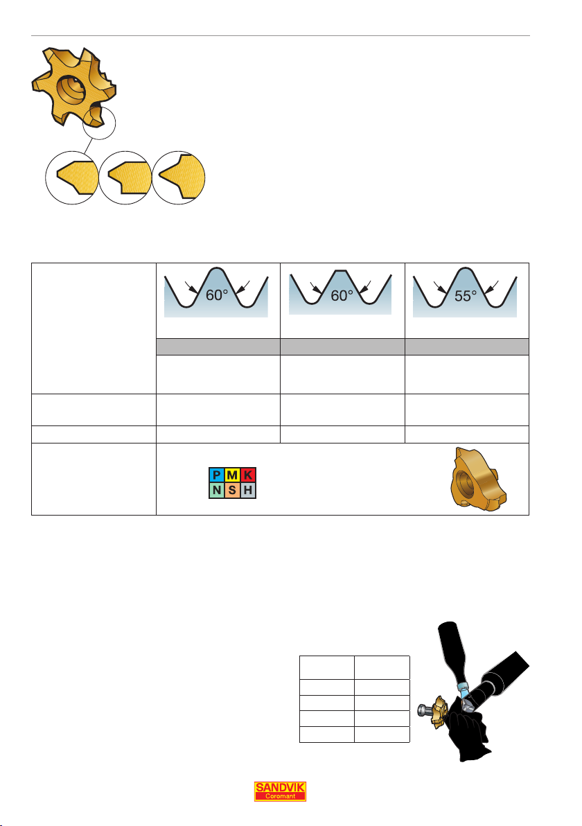
3. Products - thread millin
g
1. 2. 3.
Assortment - CoroMill® 327
Metric 60° (MM)
Pitch: 1.50 – 4.50 mm
Diameter (D
(inch)
No. of teeth (z
Grade
) mm,
c
)
n
ISO
1.
V-pro le 60°
*2.
Full pro le 60°
3.
Full pro le 55° (Whitworth)
* Compared to full pro le turning inserts, full
pro le (60°) milling inserts top only one side of
the thread form.
MM VM WH
21.7
(.854)
V-pro le 60° (VM)
Pitch: 1.00 – 4.50 mm
24 – 5 t.p.i.
11.7 – 21.7
(.461 – .854)
Whitworth 55° (WH)
19 – 11 t.p.i.
11.7
(.461)
33, 63
GC1025
hex 0.05 mm (0.02 – 0.07)
.002 inch (.0008 – .003)
Max rec. f
z
0.15 mm
.006 inch
Handling
For best performance, always clean the tip
seat before use. Pre-load the tip-seat on a new
tool by mounting and un-mounting the screw.
Use the correct torque for mounting the insert.
68
Insert
size
6 1.8
9 4.3
12 6.5
14 6.5
Torque
Page 69
g
CoroMill® 328
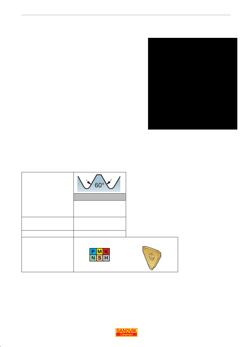
For larger holes over 39 mm (1.535 inch), CoroMill 328 offers in
serts for metric and UN threads. Inserts are pocket-mounted
for safe and stable positioning, with 3 cutting edges
per insert and high-pitch cutter bodies.
CoroMill 328 is available in versatile grade GC1025, for
all material types.
Weldon, arbor and bore with keyway mounting.
Assortment - CoroMill® 328
. Products - thread millin
VM
V-pro le 60° (VM)
Pitch: 1.50 – 6.00 mm
16 – 4 t.p.i.
Diameter (D
(inch)
No. of teeth (z
Grade
) mm,
c
)
n
39 – 100
(1.535 – 2.480)
2 – 8
ISO
hex 0.10 mm (0.05 - 0.15)
.004 inch (.002 - .006)
Max rec. f
z
0.15 mm
.006 inch
GC1025
69
Page 70
3. Products - thread millin
g
CoroMill® Plura – Multi-point threading
CoroMill Plura solid carbide thread mills produce different threads
of the same pitch with one tool. Threads are milled in one pass and
this multi-point tool gives a true full-pro le thread form, with 60°
metric, UNC/UNF and NPT/NPTF options available
CoroMill Plura is designed for smaller thread sizes in diameters
down to 3.2 mm (.126 inch) and in two optimized grade choices,
with or without through coolant. It is the ideal tool for mass production.
Easy programming
The cutting diameter of each tool has to be considered carefully
when the operation is programmed, and programming with radius
correction allows easy adjustment of thread tolerances. CoroMill
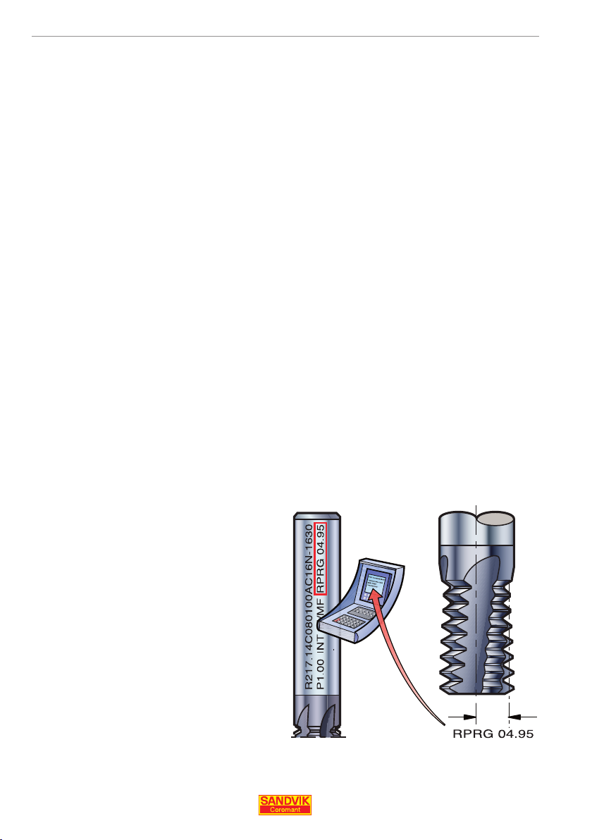
Plura has an individual radius programming (RPRG) value marked
on the shank, to indicate the exact pitch diameter and radius correction required for optimum thread quality.
The RPRG value is normally entered into the tool radius offset, and
using this will prevent the rst thread from being too large, as long
as the operational conditions are good.
For more information see chapter 5, Technical reference (page 93).
70
Tool radius programming value.
Page 71
g
Assortment - CoroMill® Plura
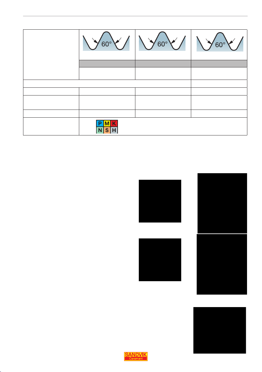
MM UNC/UNCF NPT/NPTF
Metric 60° (MM)
Pitch: 0.7 – 3.0 mm
Type of insert
Full-pro le
Diameter (D
(inch)
No. of teeth (z
ISO
) mm,
c
)
n
3.2 – 19
3 – 5 3 – 5 3 – 5
CoroMill Plura – grade selection
GC1630
With internal coolant
. Products - thread millin
UN 60° (UN)
28 – 10 t.p.i.
NPT/NPTF 60°
27 – 11.5 t.p.i.
(.189 – .551) (.311 – .783)
GC1620
GC1630
≤48 Hrc
GC1620
Without internal coolant
≤56 Hrc
Cutting data and programming
Use PluraGuide for tool selection, cutting data and programming
information.
71
Page 72
. Pr
oducts
Grade information
The wide range of carbide threading grades from Sandvik Coromant
offers high productivity for many materials and applications. Once
you have selected the most suitable tool for the threading operation, simply choose the available grade which most closely matches
your application requirements.
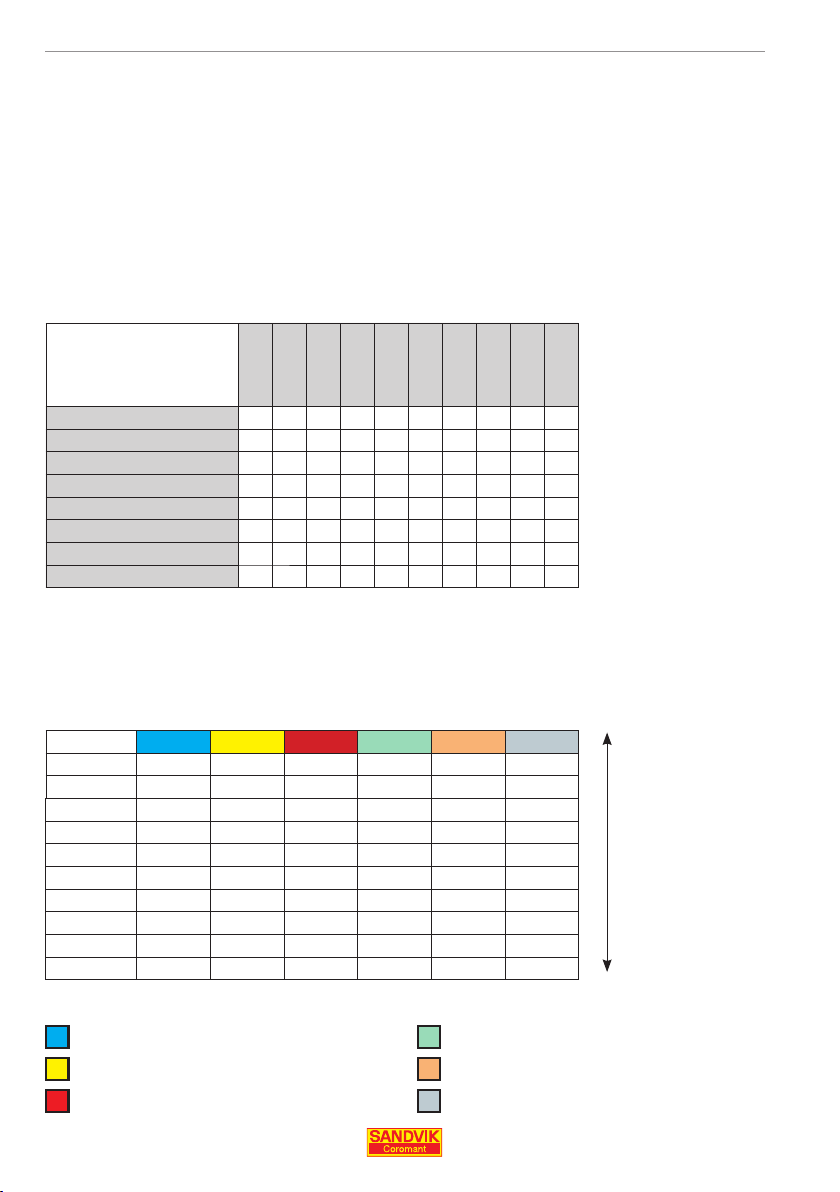
Grades available for each tooling system
GC1125
GC1135
GC1020
GC4125
GC1025
H13A
GC1105
GC1620
GC1630
CB7015
CoroThread® 266
T-Max Twin-Lock®
CoroCut® XS
CoroCut® MB
CoroTurn® XS
CoroMill® 327
CoroMill® 328
CoroMill® Plura
See chapter 4. Troubleshooting, for tips on how to optimize tool life and manage different forms of
insert wear.
Grades overview by ISO material type
Wear
resistance
(Hard grade)
Toughness
(Soft grade)
CB7015
GC1105
H13A
GC1125
GC1620
GC1630
GC4125
GC1025
GC1020
GC1135
PMKN SH
ISO P = Steel
P
ISO M = Stainless steel
M
ISO K = Cast iron
K
72
ISO N = Non-ferrous material
N
ISO S = Heat resistant super alloys
S
ISO H = Hardened materials
H
Page 73

oducts
GC1125
Coating: PVD TiCrAlN
Tools: CoroThread 266. T-Max Twin-Lock
PVD grade for ISO P, -M, -K, -N materials. Combines the superior
wear resistance of a coated grade with the edge sharpness and
toughness of an uncoated grade. Optimized for steel threading and
for speeds from medium to high.
GC1125 makes it possible to decrease the number of passes or
increase cutting speed, compared to CoroThread 266 GC1020.
GC1135
Coating: PVD TiCrAl
Tools: CoroThread 266
PVD grade for ISO M, -S, -P and -K materials, optimized for stainless
steel and heat resistant super alloys. The best choice for sharp
pro les in all materials and at speeds from medium to low.
. Pr
GC1135 makes it possible to decrease the number of passes or
increase cutting speed, compared to CoroThread 266 GC1020.
GC1020
Coating: PVD TiN
Tools: CoroThread 266
Competitive, all-round threading grade. Works best at medium
to low cutting speeds, with a thin coating ideal for sharp cutting
edges.
73
Page 74

. Pr
oducts
GC4125
Coating: PVD TiAlN
Tools: T-Max Twin-Lock
Thick, PVD coating which is more wear resistant than GC1020 – and
enables higher cutting speeds, especially in the ISO P area.
GC1025
Coating: PVD TiAlN coating (thin)
Tools: CoroCut XS, CoroCut MB, CoroTurn XS, CoroMill 327 and Coro-
Mill 328.
All-round grade for all materials and applications, with thin PVD TiAIN
coating ideal for sharp edges.
H13A
Coating: Uncoated
Tools: CoroCut XS, CoroThread 266
Uncoated grade for all materials. Good wear resistance, toughness
and edge sharpness for the ISO N area. The rst choice grade for
titanium.
CB7015
Coating: CBN-tipped
Tools: CoroCut MB
Inserts with brazed CBN tips, ideal for threading hardened components. Can be applied in the hardness range HRc 55 – 62 and for
nishing at limited cutting depths. Eliminates the need for grinding
operations
74
Page 75

oducts
GC1105
Coating: PVD TiAlN coating (thin)
Tools: CoroCut XS
First-choice grade for the ISO M and -S area. A hard substrate with
a thin coating ideal for sharp edges makes it rst choice for threading in medical components. Also with high plastic deformation
resistance.
GC1620
Coating: PVD TiAlN (thin)
Tools: CoroMill Plura
CoroMill Plura grade for semi- nishing to nishing operations
demanding wear resistance, especially in dry machining. Also performs well when machining stainless steels in wet conditions.
Covers ISO P -M -K -S -H materials, with grade hardness ≤56 HRc.
. Pr
GC1630
Coating: PVD TiAlN
Tools: CoroMill Plura
CoroMill Plura grade for roughing to semi- nishing operations demanding edge line toughness. Also performs well when machining
very soft- and smearing steels.
Covers ISO P -M -K -N -S materials, with grade hardness ≤48 HRc
.
75
Page 76
. Troubleshootin
g
4. Troubleshooting
Careful observation of the insert/cutting edge after machining can
help to optimize results regarding tool life, thread quality and cutting speed. Use this list of causes and solutions to different forms
of insert wear as a reference for successful threading.
Thread turning
Problem
Cause Solution
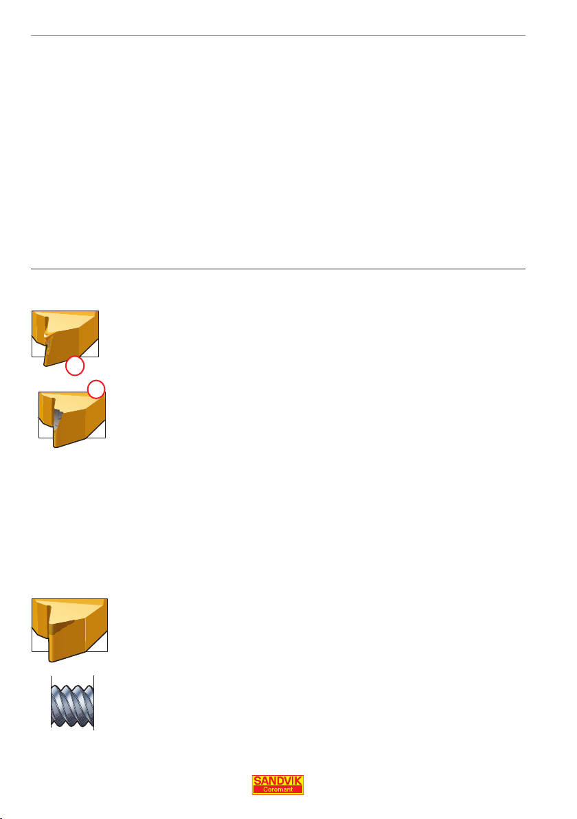
Plastic deformation
• Excessive temperature in cutting
• Inadequate supply of coolant
A
• Wrong grade
B
Starts as plastic
deformation (A).
Leads to edge chipping (B)
Rapid ank wear
• Highly abrasive material
• Cutting speed too high
• Infeed depths too shallow
• Insert is above centre line
zone
• Reduce the cutting speed, increase
the number of infeeds
• Reduce the largest infeed depth,
check the diameter before threading
• Improve coolant supply
• Choose a grade with better resistance to plastic deformation
• Choose a more wear resistant grade
• Reduce cutting speed
• Reduce number of infeeds
• Adjust to correct centre height
76
Page 77
. Troubleshooting – Thread turnin
g
Problem Cause Solution
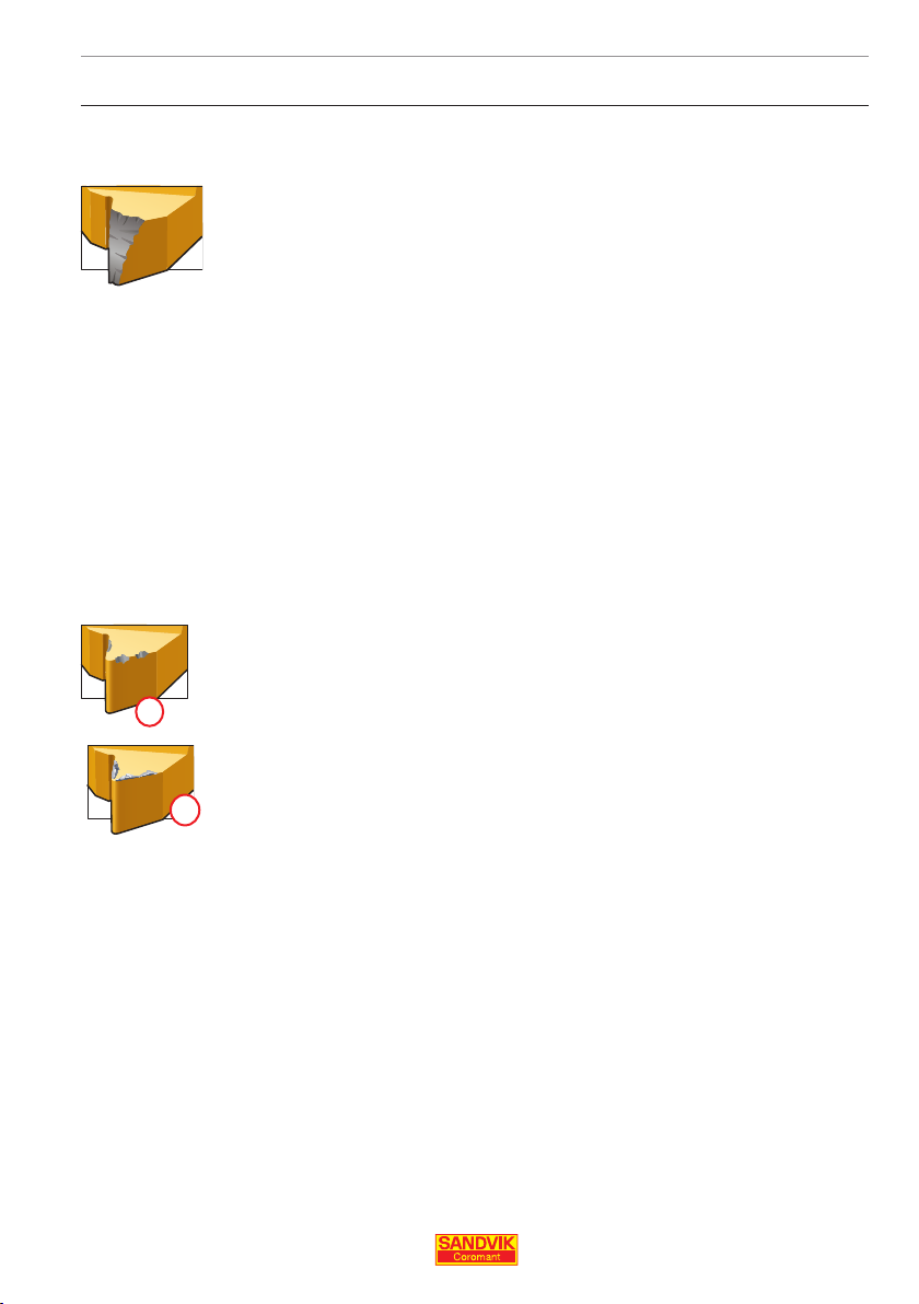
Insert breakage
• Wrong turned diameter prior to
threading
• Infeed series too tough
• Wrong grade
• Poor chip control
• Incorrect centre height
• Turn to correct diameter before
threading operation (0.03 – 0.07
mm, .001 – .003 inch) radially larger
than max. diameter for thread
• Increase number of infeeds. Reduce
size of the largest infeeds
• Choose a tougher grade
• Change to C-geometry and use
modi ed ank infeed
• Adjust to correct centre height
Built-up edge (BUE)
A
B
BUE (A) and edge
frittering (B) often
occur in combination. Accumulated
BUE is then ripped
away together with
small amounts of insert material, which
causes frittering.
• Often occurs in stainless material
• Often occurs in low carbon steel
• Unsuitable grade
• Cutting edge temperature too low
• Increase cutting speed
• Choose a grade with good toughness
77
Page 78
. Troubleshooting – Thread turnin
g
Problem Cause Solution
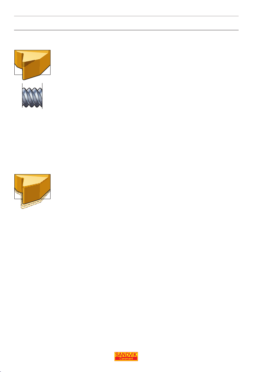
Abnormal ank wear
Poor surface on one
ank of thread.
Vibration
• Incorrect method for ank infeed
• Insert inclination angle does not
agree with the lead angle of the
thread
• Incorrect workpiece clamping
• Incorrect tool set-up
• Incorrect cutting data
• Incorrect centre height
• Change method of ank infeed for Fand A-geometry to 3 - 5° from ank.
For C-geometry to 1° from ank
• Change shim to obtain correct angle
of inclination
• Use soft jaws
• Optimize centre hole and check
pressure of face driver
Minimize overhang of tool
Check that the clamping sleeve for
bars is not worn
Use 4C anti-vibration bars
• Increase cutting speed; if this does
not help, lower the speed dramatically. Try F-geometry
• Adjust to correct centre height
• Use solid carbide shanks
78
Page 79

. Troubleshooting – Thread turnin
g
Problem Cause Solution
Poor surface nish
Poor chip control
Shallow pro le
• Cutting speed too low
• The insert is above the centre height
• Uncontrolled chips
• Re-cutting of chips
• Incorrect method of infeed
• Incorrect thread geometry
• Increase cutting speed
• Adjust centre height
• Use C-geometry and modi ed ank
infeed
• Use compressed air for evacuation
• For modi ed ank infeed use 3 - 5°
• Use C-geometry with modi ed ank
infeed 1°
• Wrong centre height
• Insert breakage
• Excessive wear
• Adjust centre height
• Change cutting edge
• Increase radial infeed
79
Page 80

. Troubleshooting – Thread turnin
g
Problem Cause Solution
Incorrect thread pro le
• Unsuitable thread pro le (angle of
thread and nose radius) external
inserts used for internal operation
or vice versa
• Wrong centre height
• Holder not 90° to centre line
• Pitch error in machine
Excessive edge pressure
• Work hardening material in combination with infeed depths which are
too shallow
• Excessive pressure on cutting edge
• Insert thread pro le angle too small
• Adjust to correct tool, shim and
insert combination
• Adjust centre height
• Adjust holder to 90°
• Correct the machine
• Reduce the number of infeeds
• Change to F-geometry
• Change to a tougher grade
• Use modi ed ank infeed
80
Page 81
. Troubleshooting – Thread m
illing
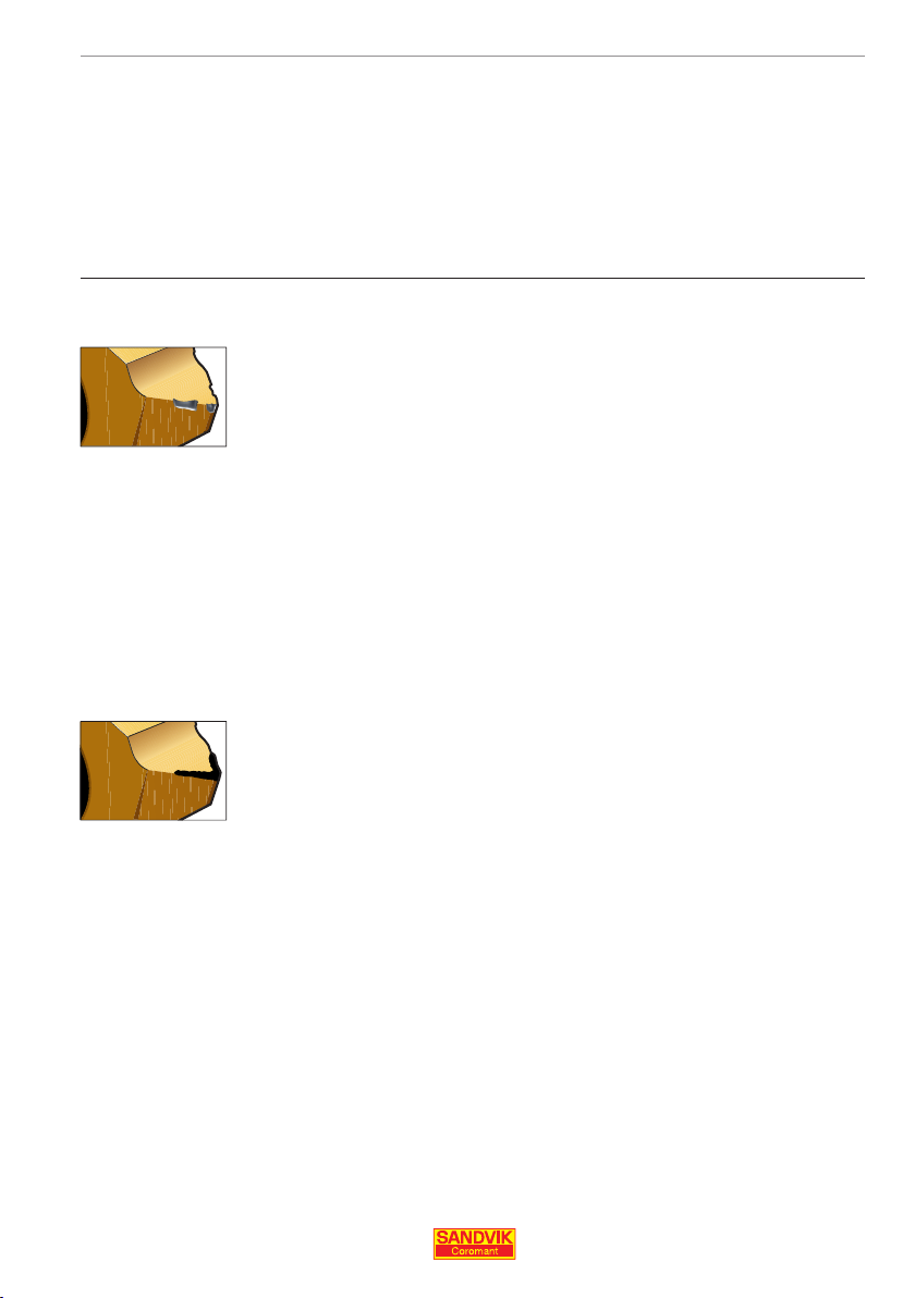
Thread milling
Problem Cause Solution
Chipping
• The part of the cutting edge which is
not in cut is damaged by chip hammering, leading to poor surface and
excessive ank wear
• Increase cutting speed
• Reduce feed at the beginning of the
cut
• Improve stability
• Increase number of infeed passes
• Use a full-pro le insert
Built-up edge (B.U.E)
Poor surface nish and cutting edge
frittering when the built-up edge is torn
away.
• Cutting zone temperature is too low.
• Very sticky material, such as low-
• Increase cutting speed or feed
• Use oil mist or cutting uid
carbon steel, stainless steels, and
aluminium.
81
Page 82
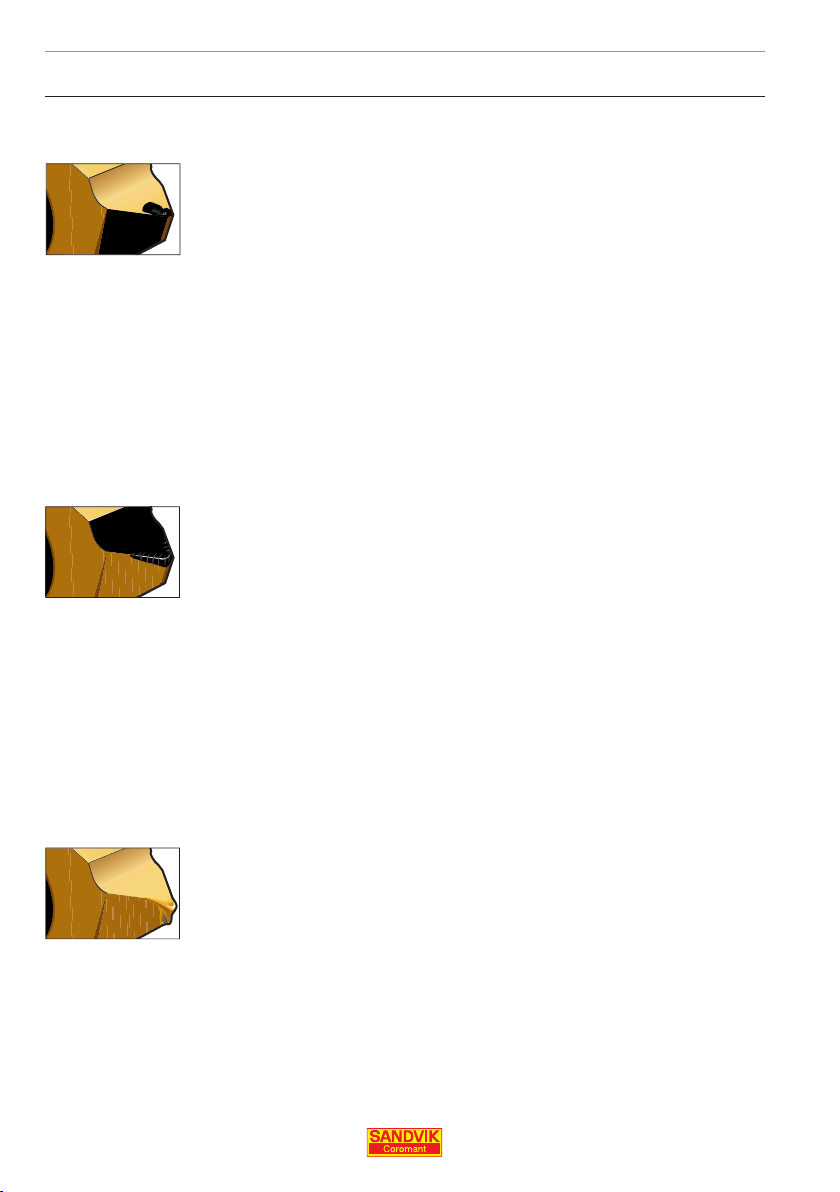
. Troubleshooting – Thread m
illing
Problem Cause Solution
Crater wear
Thermal cracks
• Excessive wear causing a weakened
edge
• Cutting edge breakthrough on the
trailing edge leading to poor surface
nish
• Temperature variations from varying
cutting uid supply or intermittent
machining leading to small cracks
perpendicular to the cutting edge,
insert frittering and poor surface
nish
• Reduce speed to reduce temperature
• Reduce feed
• Apply cutting uid in large amounts,
or not at all
• Reduce cutting speed
Plastic deformation
82
Plastic deformation of edge, depression or ank impression, leading to
poor chip control, poor surface
nish and insert breakage.
• Cutting temperature and pressure
too high
• Reduce cutting speed
• Reduce feed
Page 83
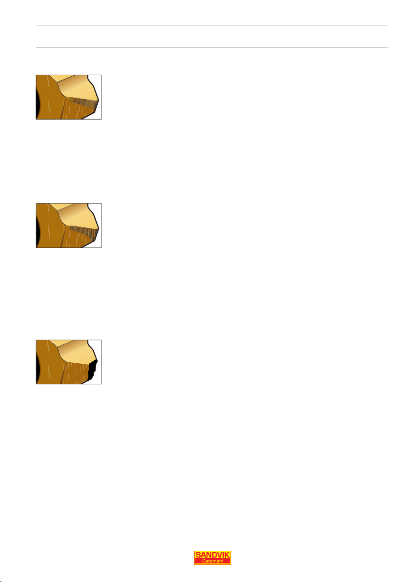
. Troubleshooting – Thread m
illing
Problem Cause Solution
Flank wear
Rapid wear causing poor surface
nish or out of
tolerance.
• Cutting speed too high
• Insuf cient wear resistance
• Feed, f
, too low
z
• Reduce cutting speed, v
• Increase feed, f
c
z
Excessive wear causing short tool
life.
• Vibration
• Re-cutting of chips
• Burr formation on component
• Poor surface nish
• Heat generation
• Excessive noise
Uneven wear causing corner damage.
• Tool run-out
• Vibration
• Short tool life
• Bad surface nish
• High noise level
• Radial forces too high
• Increase feed, f
z
• Reduce speed
• Down milling
• Evacuate chips effectively using
compressed air
• Check recommended cutting data
• Check chuck and collet
• Minimize tool overhang
• Fewer teeth in cut
• Split axial cutting depth, a
, into
p
more than one pass
• Reduce feed, f
• Reduce cutting speed, v
z
c
• HSM requires shallow passes
• Improve clamping of tool and workpiece
83
Page 84

. Troubleshooting – Thread m
illing
Problem Cause Solution
Vibration
Re-cutting of chips
• Weak xturing
• Tool overhang too long
• Insuf cient chip evacuation
• Check clamping of workpiece and
tool
• Minimize overhang
• Check tool holder run out
• Choose a tool with fewer teeth
• Increase number of infeed passes
• Increase feed per tooth
• Reduce cutting speed
• Use up-milling in nishing
• Use compressed air or large
amounts of cutting uid, preferably
through the tool
• Reduce feed per tooth
• Increase number of infeed passes
Notch wear
84
• Machining work-hardening materials
• Components with skin and scale.
• Reduce cutting speed
• Select a tougher grade
• Increase cutting speed
Page 85

. Troubleshooting – Thread millin
g
Problem Cause Solution
Machine inef ciency
Conical threads
• Machine RPM’s too low
• Cutting forces too high
• Reduce cutting speed before table
speed
• Use a smaller cutter and make
several infeed passes
• If using CoroMill Plura, change to
CoroMill 327
• Reduce tool length
• Use conventional milling
• Reduce feed
• Increase number of infeed passes
85
Page 86

5. Technical referenc
e
5. Technical reference
CoroThread® 266
Thread turning cutting speed recommendations, metric
Hardness
Brinell Grades
ISO MC No.
P
M
K
N
S
H
For more information about grades and material. see Main catalogue.
Note: Most cutting speeds are recommended for a tool life of 15 minutes.
CMC
No. Material
Steel
Unalloyed
P1.1.Z.AN 01.1 125 230 205 160
P2.1.Z.AN 02.1 180 155 140 115
P3.0.Z.AN 03.21 325 115 100 70
P5.0.Z.AN 05.11 200 160 145 90
M1.0.Z.AQ 05.21 180 140 130 75
M3.1.Z.AQ 05.51 230 110 100 -
K1.1.C.NS 07.2 230 125 110 70
K2.2.C.UT 08.2 220 140 130 80
K3.1.C.UT 09.1 160 140 135 110
N1.2.Z.UT 30.11 60 500 500 500
N1.3.C.UT 30.21 75 500 500 425
N3.2.C.UT 33.2 90 300 270 210
S1.0.U.AN 20.11 200 55 50 45
S2.0.Z.AG 20.22 350 15 15 13
S4.2.Z.AN 23.21 950 Rm 70 65 50
H1.3.Z.HA
H1.3.Z.HA
C = 0.1–0.25%
Low alloyed (alloying elements ≤ 5%)
Non-hardened
High alloyed (alloying elements > 5%)
Hardened tool steel
Stainless steel
Ferritic/matensitic
Non-hardened
Austentic
Non-hardened
Austenitic-ferritic (Duplex)
Non-weldable ≥ 0.05%C
Malleable cast iron
Pearlitic (long chipping)
Grey cast iron
High tensile strength
Nodular cast iron
Ferritic
Aluminium alloys
Wrought or wrought and coldworked. non-aging
Aluminium alloys
Cast. non-aging
Copper and copper alloys
Brass. leaded bronzes. ≤1% Pb
Heat resistant super alloys
Iron base
Annealed or solution treated
Nickel base
Aged or solution treated and aged
Titanium alloys
. near and + alloys. annealed
Extra hard steel
Hardened and tempered
04.1
04.1
GC1125 GC1135 H13A
HB Cutting speed (vc) m/min
46 HRC
60 HRC 6039
50
50
32
45
CoroTurn® XS
Cutting speed (v
GC1025
P M N S
60-200 60-180 90-400 20-50
GC7015
H
60-200
). m/min Cutting speed (vc). m/min
c
86
CoroCut® MB
GC1025
P M N S
60-200 60-180 90-400 20-50
GC7015
H
60-200
CoroCut® XS
Cutting speed (vc). m/min
GC1025/GC1105
P M N S
60-200 60-180 90-400 20-50
Page 87

. Technical referen
ce
CoroThread® 266
Thread turning cutting speed recommendations. inch
Hardness
Brinell Grades
ISO MC No.
P
M
K
N
S
H
For more information about grades and material. see Main catalogue.
Note: Most cutting speeds are recommended for a tool life of 15 minutes.
CMC
No. Material
Steel
Unalloyed
P1.1.Z.AN 01.1 125 760 670 510
P2.1.Z.AN 02.1 180 510 460 380
P3.0.Z.AN 03.21 325 375 320 230
P5.0.Z.AN 05.11 200 520 475 295
M1.0.Z.AQ 05.21 180 460 425 250
M3.1.Z.AQ 05.51 230 360 330 -
K1.1.C.NS 07.2 230 410 360 230
K2.2.C.UT 08.2 220 460 425 265
K3.1.C.UT 09.1 160 460 450 355
N1.2.Z.UT 30.11 60 1650 1650 1650
N1.3.C.UT 30.21 75 1650 1650 1400
N3.2.C.UT 33.2 90 980 890 490
S1.0.U.AN 20.11 200 180 165 145
S2.0.Z.AG 20.22 350 50 50 45
S4.2.Z.AN 23.21 950 Rm 560 520 -
H1.3.Z.HA
H1.3.Z.HA
C = 0.1–0.25%
Low alloyed (alloying elements ≤ 5%)
Non-hardened
High alloyed (alloying elements ≤ 5%)
Hardened tool steel
Stainless steel
Ferritic/matensitic
Non-hardened
Austentic
Non-hardened
Austenitic-ferritic (Duplex)
Non-weldable ≥ 0.05%C
Malleable cast iron
Pearlitic (long chipping)
Grey cast iron
High tensile strength
Nodular cast iron
Ferritic
Aluminium alloys
Wrought or wrought and coldworked. non-aging
Aluminium alloys
Cast. non-aging
Copper and copper alloys
Brass. leaded bronzes. ≤1% Pb
Heat resistant super alloys
Iron base
Annealed or solution treated
Nickel base
Aged or solution treated and aged
Titanium alloys
. near and + alloys. annealed
Extra hard steel
Hardened and tempered
04.1
04.1
GC1125 GC1135 H13A
HB Cutting speed (vc) ft/min
46 HRC
60 HRC
200
125
165
105
-
-
CoroTurn® XS
Cutting speed (v
GC1025
P M N S
196-656 196-590 295-1312 65-164
GC7015
H
196-656
). ft/min Cutting speed (vc). ft/min Cutting speed (vc). ft/min
c
CoroCut® MB
GC1025
P M N S
196-656 196-590 295-1312 65-164
GC7015
H
196-656
CoroCut® XS
GC1025/GC1105
P M N S
196-656 196-590 295-1312 65-164
87
Page 88

5. Technical referenc
e
CoroMill® 327 and CoroMill® 328
Thread milling cutting speed recommendations with grade GC1025, metric
Speci c cutting force k
ISO MC No.
P
M
K
N
S
H
CMC
No. Material N/mm
Steel
Unalloyed
P1.1.Z.AN 01.1 1500 125 0.25 365–360–345
P2.1.Z.AN 02.1 1700 175 0.25 300–295–285
P3.0.Z.AN 03.21 2900 300 0.25 140–140–135
P5.0.Z.AN 05.11 1800 200 0.21 255–225–180
M1.0.Z.AQ 05.21 1950 200 0.21 250–225–180
M3.1.Z.AQ 05.51 2000 230 0.21 205–185–145
K1.1.C.NS 07.2 900 230 0.28 240–195–160
K2.2.C.UT 08.2 1100 245 0.28 255–210–170
K3.1.C.UT 09.1 900 160 0.28 200–165–135
N1.2.Z.UT 30.11 400 60 990–910–850
N1.3.C.UT 30.21 600 75 0.25 990–910–850
N3.2.C.UT 33.2 550 90 495–460–425
S1.0.U.AN 20.11 2400 200 0.25 65–60–55
S2.0.Z.AG 20.22 2900 350 0.25 37–34–32
S4.2.Z.AN 23.21 1400 950 0.23 70–65–60
H1.3.Z.HA 04.1 4200 59 HRC 0.25 40–36–29
C = 0.1–0.25%
Low alloyed (alloying elements ≤ 5%)
Non-hardened
High alloyed (alloying elements ≤ 5%)
Hardened tool steel
Stainless steel
Ferritic/matensitic
Non-hardened
Austentic
Non-hardened
Austenitic-ferritic (Duplex)
Non-weldable ≥ 0.05%C
Malleable cast iron
Pearlitic (long chipping)
Grey cast iron
High tensile strength
Nodular cast iron
Ferritic
Aluminium alloys
Wrought or wrought and coldworked. non-aging
Aluminium alloys
Cast. non-aging
Copper and copper alloys
Brass. leaded bronzes. ≤1% Pb
Heat resistant super alloys
Iron base
Annealed or solution treated
Nickel base
Aged or solution treated and aged
Titanium alloys
. near and + alloys. annealed
Extra hard steel
Hardened and tempered
Hardness
Brinell
c
2
HB mc
Max chip thickness.
hex mm
0.05–0.1–0.15
Cutting speed v
m/min
.
c
88
Page 89

CoroMill® 327 and CoroMill® 328
Thread milling cutting speed recommendations with grade GC1025, inch
Speci c cutting force k
ISO MC No.
P
M
K
N
S
H
CMC
No. Material lbs/in
Steel
Unalloyed
P1.1.Z.AN 01.1 216,500 125 0.25 1200-1200-1150
P2.1.Z.AN 02.1 246,500 175 0.25 990-970-930
P3.0.Z.AN 03.21 420,000 300 0.25 465-455-435
P5.0.Z.AN 05.11 262,000 200 0.21 910-890-840
M1.0.Z.AQ 05.21 285,000 200 0.21 890-870-830
M3.1.Z.AQ 05.51 286,500 230 0.21 740-720-680
K1.1.C.NS 07.2 131,000 230 0.28 970-950-900
K2.2.C.UT 08.2 159,500 245 0.28 1000-1000-960
K3.1.C.UT 09.1 130,000 160 0.28 800-780-750
N1.2.Z.UT 30.11 58,000 60 3650-3600-3500
N1.3.C.UT 30.21 87,000 75 0.25 3650-3600-3500
N3.2.C.UT 33.2 80,000 90 1850-1800-1750
S1.0.U.AN 20.11 348,000 200 0.25 220-215-215
S2.0.Z.AG 20.22 420,500 350 0.25 130-130-125
S4.2.Z.AN 23.21 203,000 950 0.23 185-180-175
H1.3.Z.HA 04.1 606,500 59 HRC 0.25 215-215-195
C = 0.1–0.25%
Low alloyed (alloying elements ≤ 5%)
Non-hardened
High alloyed (alloying elements ≤ 5%)
Hardened tool steel
Stainless steel
Ferritic/matensitic
Non-hardened
Austentic
Non-hardened
Austenitic-ferritic (Duplex)
Non-weldable ≥ 0.05%C
Malleable cast iron
Pearlitic (long chipping)
Grey cast iron
High tensile strength
Nodular cast iron
Ferritic
Aluminium alloys
Wrought or wrought and coldworked. non-aging
Aluminium alloys
Cast. non-aging
Copper and copper alloys
Brass. leaded bronzes. ≤1% Pb
Heat resistant super alloys
Iron base
Annealed or solution treated
Nickel base
Aged or solution treated and aged
Titanium alloys
α. near α and α + β alloys. annealed
Extra hard steel
Hardened and tempered
Hardness
Brinell
c
2
HB mc
Max chip thickness.
Cutting speed vc.
hex inch
.002–.004-.008
ft/min
89
Page 90
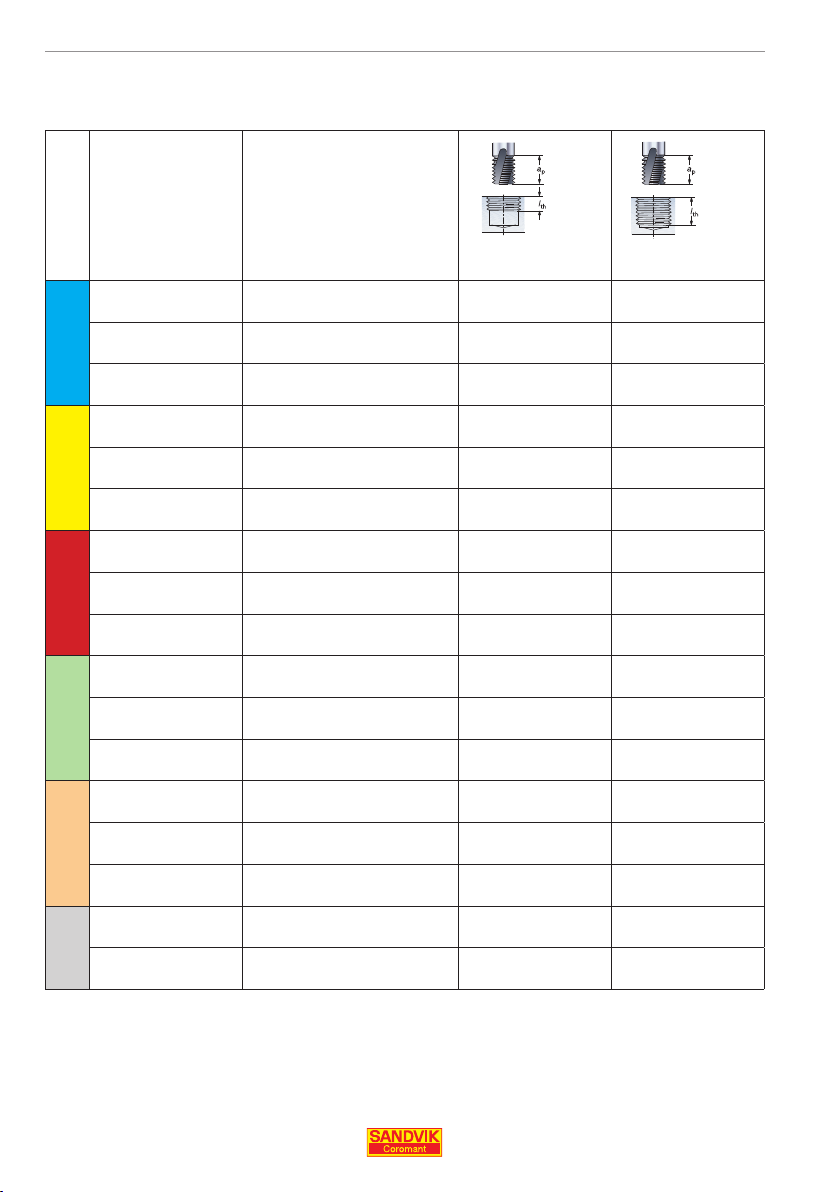
5. Technical referenc
e
CoroMill® Plura
Thread milling cutting data recommendations. metric
Material Thread mill Dimensions, mm
CMC No. Hardness
. mm
z
Cutting
ISO HB HRC Thread
Unalloyed steel
P
01.1 125 M10 8.2 4 • 132 0.052 124 0.029
Low alloy steel
02.2 300 M10 8.2 4 • 164 0.086 153 0.05
High alloy steel
03.21 450 M10 8.2 4 • 164 0.061 153 0.049
Stainless steel
M
05.11 200 M10 8.2 4 • 82 0.052 76 0.036
05.21 200 M10 8.2 4 • 53 0.052 50 0.027
05.51 230 M10 8.2 4 • 53 0.052 50 0.027
Malleable cast iron
K
07.2 M10 8.2 4 • 89 0.061 83 0.036
Nodular cast iron
08.2 M10 8.2 4 • 86 0.038 79 0.034
Grey cast iron
09.1 M10 8.2 4 • 104 0.047 105 0.048
Aluminium
N
30.11 60 M10 8.2 4 • 1120 0.089 1060 0.061
30.21 95 M10 8.2 4 • 461 0.061 432 0.061
33.2 150 M10 8.2 4 • 278 0.053 260 0.026
Heat resistant alloys
S
20.11 200 M10 8.2 4 • 37 0.023 35 0.013
Titanium alloys
20.22 300 M10 8.2 4 • 32 0.013 30 0.007
23.21 300 M4 3.2 3 – 55 0.012 51 0.060
Hardened steel
H
04.1 55 M10 8.2 5 – 42 0.022 45 0.035
04.1 60 M4 4.5 4 – 30 0.005 30 0.003
M4 3.2 3 – 152 0.030 141 0.018
M20 16 5 • 141 0.130 131 0.069
M4 3.2 3 – 147 0.012 137 0.006
M20 16 5 • 173 0.089 162 0.118
M4 3.2 3 – 163 0.035 151 0.015
M20 16 5 • 173 0.012 162 0.118
M4 3.2 3 – 81 0.024 75 0.009
M20 16 5 • 86 0.089 93 0.089
M4 3.2 3 – 53 0.018 49 0.007
M20 16 5 • 56 0.089 53 0.072
M4 3.2 3 – 53 0.018 49 0.007
M20 16 5 • 56 0.131 53 0.074
M4 3.2 3 – 80 0.020 77 0.016
M20 16 5 • 82 0.084 83 0.089
M4 3.2 3 – 76 0.018 73 0.014
M20 16 5 • 79 0.075 80 0.080
M4 3.2 3 – 101 0.027 97 0.020
M20 16 5 • 104 0.089 97 0.067
M4 3.2 3 – 503 0.040 503 0.035
M20 16 5 • 1130 0.089 1060 0.089
M4 3.2 3 – 434 0.040 404 0.014
M20 16 5 • 467 0.089 436 0.089
M4 3.2 3 – 273 0.028 262 0.021
M20 16 5 • 282 0.089 263 0.071
M4 3.2 3 – 35 0.006 35 0.003
M20 16 5 • 38 0.066 38 0.063
M4 3.2 3 – 30 0.030 29 0.020
M20 16 5 • 32 0.037 30 0.018
M10 8.2 4 • 58 0.037 54 0.020
M20 12 6 • 59 0.089 55 0.051
M4 4.5 4 – 43 0.010 40 0.005
M20 12 5 – 45 0.042 42 0.021
M10 8.2 5 – 29 0.011 28 0.006
M20 12 5 – 30 0.022 28 0.010
D
z
c
n
With internal
coolant supply
speed vc.
m/min
Cutting
speed vc.
Feed/tooth f
m/min
. mm
z
Feed/tooth f
90
Page 91

ce
CoroMill® Plura
Thread milling cutting data recommendations. inch
Material Thread mill Dimensions, inch
CMC No. Hardness
. Technical referen
. mm
z
Cutting
ISO HB HRC Thread
Unalloyed steel
P
01.1 125 M10 .323 4 • 435 .0020 410 .0012
Low alloy steel
02.2 300 M10 323 4 • 540 .0034 500 .0020
High alloy steel
03.21 450 M10 .323 4 • 550 .0024 520 .0020
Stainless steel
M
05.11 200 M10 .323 4 • 270 .0020 250 .0014
05.21 200 M10 .323 4 • 175 .0020 165 .0012
05.51 230 M10 .323 4 • 175 .0020 165 .0012
Malleable cast iron
K
07.2 M10 .323 4 • 290 .0022 275 .0014
Nodular cast iron
08.2 M10 .323 4 • 310 .0014 285 .0013
Grey cast iron
09.1 M10 .323 4 • 345 .0020 340 .0020
Aluminium
N
30.11 60 M10 .323 4 • 3700 .0036 3500 .0024
30.21 95 M10 .323 4 • 1520 .0025 1420 .0034
33.2 150 M10 .323 4 • 920 .0021 870 .0012
Heat resistant alloys
S
20.11 200 M10 .323 4 • 120 .0011 115 .0006
Titanium alloys
20.22 300 M10 .323 4 • 105 .0006 100 .0003
23.21 300 M4 .126 3 – 180 .0005 165 .0002
Hardened steel
H
04.1 55 M10 .323 5 – 135 .0010 150 .0014
04.1 60 M4 .177 4 – 100 .0002 100 .0001
M4 .126 3 – 500 .0012 465 .0007
M20 .630 5 • 465 .0051 430 .0028
M4 .126 3 – 485 .0005 440 .0003
M20 .630 5 • 570 .0036 535 .0046
M4 .126 3 – 540 .0014 500 .0006
M20 .630 5 • 570 .0005 540 .0046
M4 .126 3 – 265 .0010 245 .0004
M20 .630 5 • 280 .0036 310 .0036
M4 .126 3 – 175 .0007 160 .0007
M20 .630 5 • 185 .0036 170 .0029
M4 .126 3 – 175 .0008 160 .0003
M20 .630 5 • 185 .0052 175 .0030
M4 .126 3 – 265 .0008 260 .0006
M20 .630 5 • 270 .0032 275 .0036
M4 .126 3 – 260 .0007 250 .0006
M20 .630 5 • 285 .0030 290 .0032
M4 .126 3 – 340 .0012 330 .0008
M20 .630 5 • 345 .0036 330 .0026
M4 .126 3 – 1660 .0016 1660 .0014
M20 .630 5 • 3750 .0036 3500 .0036
M4 .126 3 – 1430 .0016 1330 .0007
M20 .630 5 • 1540 .0036 1445 .0036
M4 .126 3 – 900 .0011 890 .0009
M20 .630 5 • 930 .0036 880 .0028
M4 .126 3 – 115 .0002 115 .0001
M20 .630 5 • 125 .0026 125 .0025
M4 .126 3 – 100 .0012 100 .0008
M20 .630 5 • 105 .0015 100 .0007
M10 .323 4 • 190 .0015 175 .0008
M20 .630 6 • 195 .0036 180 .0022
M4 .177 4 – 140 .0004 130 .0002
M20 .427 5 – 150 .0017 135 .0009
M10 .323 5 – 100 .0005 100 .0002
M20 .472 5 – 100 .0010 100 .0004
D
z
c
n
With internal
coolant supply
speed vc.
ft/min
Cutting
speed vc.
Feed/tooth f
ft/min
. mm
z
Feed/tooth f
91
Page 92

5. Technical referenc
e
Programming
Modern machine tools use computer numerical control (CNC) methods to produce complex parts in a consistent and automated manner. This capability is especially important when producing threads.
CNC machines can process 2-dimensional and 3-dimensional
shapes using their coordinate axes, with each machine typically
having 3-axis (X, Y, Z) - though machines with up to 12-axes do exist. For threading, the methods of CNC programming differ in lathes
and machining centres and dedicated CNC programs exist for
threading and turning.
Programming – lathe
When thread turning, it is important to use the correct CNC code
to ensure good tool life, chip control, surface and tolerance. Fixed
cycles, or the dialog system are common ways to program a lathe
for threading. However, line programming (long-hand code) is the
optimum method and can be used with all CNC systems.
Obtaining the correct infeed (thread turning)
Modi ed- ank infeed and radial infeed are the preferred methods of
achieving good threading results. Line programming is recommended to accurately control the infeed angle and number of passes.
Recommendations (thread turning)
• Correct thread programming is important - especially for large
threads and pitches.
• Use the recommended infeed depth in CoroGuide to ensure the
correct number of passes.
• With ank infeed, the angular displacement must also be calculated.
92
Page 93

ce
Example ISO longhand code (lathe)
T0101 (THREADING TOOL)
G97 S2103 M3
G0 X26.0 Z8.5 M8
G0 X23.623 Z4.5
G32 Z-26.5 F2.0
G0 X26.0
G0 Z4.404
G0 X23.083
G32 Z-26.5 F2.0
G32 is the command for the threading movement in the machine.
This code can differ depending of the CNC system (check your
machine manual to con rm). If the start point for the threading
operation varies in the z-axis, the thread should be programmed
with ank infeed.
Programming – machining centre
In thread milling; rolling in and out of cut achieves good tool life
and high thread quality
When programming a large thread pro le, it may be necessary to
split up the machining into at least two passes.
. Technical referen
The most useful software for selection of cutting data, tool and
programming a thread with a milling cutter is PluraGuide (non-CAM
software).
The only difference between programming CoroMill Plura and
CoroMill 327/CoroMill 328 is the need to repeat the circular
motion until the correct thread depth has been reached (circular
ramping).
Programming the feed rate on most machining centres is based on
the centre line of the spindle. This must be taken into account to
avoid shortened tool life, vibration or tool breakdown.
93
Page 94
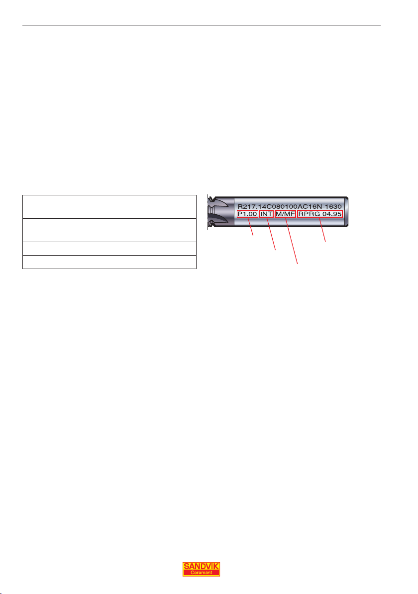
. Technical r
eference
CoroMill® Plura
CoroMill Plura has an individual radius programming value (RPRG)
marked on the shank of the tool.
The RPRG value indicates each cutter’s exact pitch diameter and
the radius required for optimum thread quality.
The RPRG value is normally entered into the tool memory offset.
Using the RPRG will prevent the rst thread from being too large, as
long as the operational conditions are good.
Climb milling
Cutting speed v
Feed per tooth 0.059 mm
Time/thread
6H
127 m/min
c
5000 inch/min
.0023 inch
6
“Rprg” - 0.053 mm
Pitch
Internal
thread
Thread
type
Individual tool radius programming
value
Example CNC code (machining centre)
CNC programme - FANUC
(M6) T
Tool call-in
G90 G17
Selection of working plane
S3369 M3
G00 G43H...X0.000 YO.000 Z2.000
2 mm “above” workpiece surface on centerline of thread
94
Page 95

eference
G00 Z-21.000
Move to required depth on centerline of the pre-drilled hole
G41 D... G01 X0.000 Y6.000 F994
Set approach path for entry loop
G03 X0.000 Y-8.000 Z-20.000 10.000 J-7.000 F121
Move to the contour starting point
G03 X0.000 Y-8.000 Z-18.000 10.000 J8.000 F249
Thread milling
G03 X0.000 Y-6.000 Z-17.000 10.000 J7.000
Move clear of the contour
G40 G01 X0.000 Y0.000
Re-set to centerline
G00 Z2.000
Retract from thread
You can use the RPRG value marked on the tool as starting value
for new thread milling cutters.
The feed rates of the radii have already been adjusted. If your
control reduces the feed rate for concave forms automatically, the
additionally reduced values for the circular path are not needed. If
you need to recalculate the feed for thread milling, see recommendations on page 88-91.
Repeat this program for
CoroMill 327/CoroMill 328.
until the right thread depth is
achieved.
. Technical r
95
Page 96
. Technical r
eference
Thread turning infeed recommendations
ISO Metric (MM), external
Pitch, mm
No. of
infeeds Unit Radial infeed per pass
1 0.10 0.16 0.16 0.17 0.20 0.17 0.20 0.20 0.20 0.24 0.24 0.27 0.29 0.27 0.30
2 0.09 0.15 0.15 0.15 0.19 0.17 0.19 0.19 0.19 0.23 0.22 0.25 0.28 0.26 0.29
3 0.08 0.12 0.14 0.14 0.18 0.16 0.18 0.18 0.19 0.22 0.22 0.24 0.27 0.26 0.29
4 0.07 0.07 0.12 0.13 0.16 0.15 0.17 0.17 0.18 0.21 0.21 0.23 0.26 0.25 0.28
5 0.08 0.12 0.14 0.14 0.16 0.17 0.17 0.21 0.21 0.23 0.25 0.25 0.27
6 0.08 0.08 0.13 0.15 0.16 0.17 0.20 0.20 0.22 0.25 0.24 0.26
7 0.11 0.13 0.15 0.16 0.18 0.19 0.21 0.24 0.23 0.26
8 0.08 0.08 0.14 0.15 0.17 0.18 0.20 0.23 0.23 0.25
9 0.12 0.14 0.16 0.17 0.19 0.22 0.22 0.24
10 0.08 0.13 0.15 0.16 0.18 0.20 0.21 0.23
11 0.12 0.13 0.15 0.17 0.19 0.20 0.22
12 0.08 0.08 0.14 0.16 0.17 0.19 0.20
13 0.12 0.14 0.15 0.18 0.19
14 0.08 0.10 0.10 0.16 0.17
15 0.14 0.15
16 0.10 0.10
Total infeedmminch
0.50 0.75 1.00 1.25 1.50 1.75 2.00 2.50 3.00 3.50 4.00 4.50 5.00 5.50 6.00
mm
inch
.004 .006 .006 .007 .008 .007 .008 .008 .008 .009 .009 .011 .011 .011 .012
mm
inch
.004 .006 .006 .006 .007 .007 .007 .007 .007 .009 .009 .010 .011 .010 .011
mm
inch
.003 .005 .006 .006 .007 .006 .007 .007 .007 .009 .009 .009 .011 .010 .260
mm
inch
.003 .003 .005 .005 .006 .006 .007 .007 .007 .008 .008 .009 .010 .010 .011
mm
inch
mm
inch
mm
inch
mm
inch
mm
inch
mm
inch
mm
inch
mm
inch
mm
inch
mm
inch
mm
inch
mm
inch
0.34 0.50 0.65 0.79 0.95 1.11 1.26 1.56 1.88 2.18 2.49 2.79 3.10 3.39 3.70
.013 .020 .026 .031 .037 .044 .050 .061 .227 .086 .098 .110 .122 .133 .146
.003 .005 .006 .006 .006 .007 .007 .008 .008 .009 .010 .010 .011
.003 .003 .005 .006 .006 .160 .008 .008 .009 .010 .009 .010
.004 .005 .006 .006 .007 .007 .008 .009 .009 .010
.003 .003 .006 .006 .007 .007 .008 .009 .009 .010
.005 .006 .006 .007 .007 .009 .009 .009
.003 .005 .006 .006 .007 .008 .008 .009
.005 .005 .006 .007 .007 .008 .009
.003 .003 .006 .006 .007 .007 .008
.005 .006 .006 .007 .007
.003 .004 .004 .006 .007
.006 .006
.004 .004
96
Extra stock is included in the total infeed 0.05 mm
Reference material
.002 inch
CMC 02.1
MC P2.1.Z.AN
Page 97
eference
Thread turning infeed recommendations
. Technical r
ISO Metric (MM), internal
Pitch, mm
No. of
infeeds Unit Radial infeed per pass
1 0.10 0.15 0.15 0.16 0.20 0.16 0.19 0.19 0.19 0.22 0.21 0.23 0.26 0.25 0.28
2 0.09 0.14 0.14 0.15 0.18 0.15 0.18 0.18 0.18 0.21 0.21 0.23 0.26 0.25 0.27
3 0.08 0.12 0.13 0.14 0.17 0.15 0.17 0.17 0.18 0.20 0.20 0.22 0.25 0.24 0.26
4 0.07 0.07 0.12 0.13 0.15 0.14 0.16 0.17 0.17 0.20 0.19 0.22 0.24 0.24 0.26
5 0.08 0.11 0.13 0.13 0.15 0.16 0.16 0.19 0.19 0.21 0.24 0.23 0.25
6 0.08 0.08 0.12 0.14 0.15 0.16 0.18 0.18 0.20 0.23 0.22 0.24
7 0.11 0.12 0.14 0.15 0.17 0.18 0.20 0.22 0.22 0.24
8 0.08 0.08 0.13 0.14 0.16 0.17 0.19 0.21 0.21 0.23
9 0.12 0.14 0.15 0.16 0.18 0.20 0.20 0.22
10 0.08 0.12 0.14 0.15 0.17 0.19 0.20 0.21
11 0.11 0.12 0.14 0.16 0.18 0.19 0.20
12 0.08 0.08 0.13 0.15 0.16 0.18 0.19
13 0.12 0.14 0.15 0.17 0.18
14 0.08 0.10 0.10 0.16 0.16
15 0.14 0.15
16 0.10 0.10
Total infeedmminch
0.50 0.75 1.00 1.25 1.50 1.75 2.00 2.50 3.00 3.50 4.00 4.50 5.00 5.50 6.00
mm
inch
.004 .006 .006 .006 .008 .006 .007 .007 .007 .009 .008 .009 .010 .010 .011
mm
inch
.004 .005 .006 .006 .007 .006 .007 .007 .007 .008 .008 .009 .010 .010 .011
mm
inch
.003 .005 .005 .006 .007 .006 .007 .007 .007 .008 .008 .009 .010 .010 .010
mm
inch
.003 .003 .005 .005 .006 .006 .006 .007 .007 .008 .008 .009 .010 .009 .010
mm
inch
mm
inch
mm
inch
mm
inch
mm
inch
mm
inch
mm
inch
mm
inch
mm
inch
mm
inch
mm
inch
mm
inch
0.34 0.48 0.63 0.77 0.92 1.05 1.20 1.48 1.78 2.03 2.31 2.61 2.88 3.19 3.44
.013 .019 .025 .030 .036 .041 .047 .058 .070 .080 .091 .103 .113 .126 .135
.003 .005 .005 .005 .006 .006 .006 .007 .007 .008 .009 .009 .010
.003 .003 .005 .005 .006 .006 .007 .007 .008 .009 .009 .010
.004 .005 .006 .006 .007 .007 .008 .009 .009 .009
.003 .003 .005 .006 .006 .007 .007 .008 .008 .009
.005 .005 .006 .006 .007 .008 .008 .009
.003 .005 .005 .006 .007 .007 .008 .008
.004 .005 .006 .006 .007 .007 .008
.003 .003 .005 .006 .006 .007 .008
.005 .005 .006 .007 .007
.003 .004 .004 .006 .006
.005 .006
.004 .004
Extra stock is included in the total infeed 0.05 mm
Reference material
.002 inch
CMC 02.1
MC P2.1.Z.AN
97
Page 98
. Technical r
eference
Thread turning infeed recommendations
ISO inch (UN), external
Pitch, t.p.i.
No. of
infeeds Unit Radial infeed per pass
1 0.17 0.15 0.18 0.18 0.20 0.19 0.18 0.20 0.22 0.21 0.21 0.21 0.22 0.25 0.24 0.29 0.28 0.32
2 0.16 0.14 0.16 0.17 0.18 0.18 0.18 0.19 0.21 0.20 0.20 0.20 0.21 0.24 0.23 0.29 0.28 0.32
3 0.13 0.13 0.15 0.15 0.17 0.17 0.17 0.18 0.20 0.19 0.19 0.19 0.20 0.23 0.23 0.28 0.27 0.31
4 0.08 0.11 0.13 0.14 0.15 0.16 0.16 0.17 0.19 0.18 0.18 0.19 0.20 0.22 0.22 0.27 0.26 0.30
5 0.08 0.08 0.12 0.13 0.14 0.15 0.16 0.17 0.17 0.17 0.18 0.19 0.21 0.21 0.26 0.26 0.29
6 0.08 0.08 0.12 0.14 0.14 0.15 0.16 0.16 0.17 0.18 0.20 0.21 0.25 0.25 0.28
7 0.08 0.12 0.12 0.13 0.15 0.15 0.16 0.17 0.19 0.20 0.24 0.24 0.27
8 0.08 0.08 0.08 0.13 0.14 0.15 0.16 0.18 0.19 0.23 0.23 0.26
9 0.08 0.12 0.14 0.15 0.17 0.18 0.22 0.22 0.25
10 0.08 0.12 0.14 0.15 0.18 0.21 0.22 0.24
11 0.08 0.12 0.13 0.17 0.19 0.21 0.23
12 0.08 0.08 0.15 0.18 0.19 0.22
13 0.14 0.15 0.18 0.20
14 0.10 0.10 0.17 0.18
15 0.15 0.16
16 0.10 0.10
Total infeedmminch
3228242018161413121110987654.54
mm
inch
.007 .006 .007 .007 .008 .007 .007 .008 .009 .008 .008 .008 .009 .010 .009 .012 .011 .013
mm
inch
.006 .005 .006 .007 .007 .007 .007 .007 .008 .008 .008 .008 .008 .009 .009 .011 .011 .012
mm
inch
.005 .005 .006 .006 .007 .007 .007 .007 .008 .008 .008 .008 .008 .009 .009 .011 .011 .012
mm
inch
.003 .004 .005 .006 .006 .006 .006 .007 .007 .007 .007 .007 .008 .009 .009 .011 .010 .012
mm
inch
mm
inch
mm
inch
mm
inch
mm
inch
mm
inch
mm
inch
mm
inch
mm
inch
mm
inch
mm
inch
mm
inch
.003 .003 .005 .005 .006 .006 .006 .007 .007 .007 .007 .007 .008 .008 .010 .010 .011
.003 .003 .005 .005 .006 .006 .006 .006 .007 .007 .008 .008 .010 .010 .011
.003 .005 .005 .005 .006 .006 .006 .007 .008 .008 .010 .010 .011
.003 .003 .003 .005 .006 .006 .006 .007 .008 .009 .009 .010
.003 .005 .005 .006 .007 .007 .009 .009 .010
.003 .005 .005 .006 .007 .008 .008 .010
.003 .005 .005 .007 .008 .008 .009
.003 .003 .006 .007 .008 .008
.005 .006 .007 .008
.004 .004 .007 .007
0.54 0.60 0.70 0.84 0.92 1.04 1.17 1.24 1.35 1.47 1.62 1.79 2.02 2.26 2.64 3.17 3.51 3.94
.021 .024 .028 .033 .036 .041 .046 .049 .053 .058 .064 .070 .080 .089 .104 .125 .138 .155
.006 .006
.004 .004
98
Extra stock is included in the total infeed 0.05 mm
Reference material
.002 inch
CMC 02.1
MC P2.1.Z.AN
Page 99
eference
Thread turning infeed recommendations
. Technical r
ISO inch (UN), internal
Pitch, t.p.i.
No. of
infeeds Unit Radial infeed per pass
1 0.16 0.14 0.16 0.16 0.18 0.17 0.16 0.18 0.20 0.19 0.19 0.19 0.19 0.23 0.21 0.27 0.28 0.30
2 0.14 0.13 0.15 0.15 0.17 0.16 0.16 0.17 0.19 0.18 0.18 0.18 0.19 0.22 0.21 0.26 0.27 0.29
3 0.13 0.12 0.14 0.14 0.16 0.15 0.15 0.16 0.18 0.18 0.17 0.18 0.18 0.21 0.20 0.25 0.27 0.28
4 0.08 0.11 0.12 0.13 0.14 0.14 0.14 0.16 0.17 0.17 0.17 0.17 0.18 0.21 0.20 0.25 0.26 0.27
5 0.08 0.08 0.12 0.13 0.13 0.14 0.15 0.16 0.16 0.16 0.16 0.17 0.20 0.19 0.24 0.25 0.27
6 0.08 0.08 0.12 0.13 0.13 0.14 0.15 0.15 0.16 0.16 0.19 0.19 0.23 0.25 0.26
7 0.08 0.11 0.12 0.13 0.14 0.14 0.15 0.16 0.18 0.18 0.22 0.24 0.25
8 0.08 0.08 0.08 0.12 0.13 0.14 0.15 0.17 0.18 0.21 0.23 0.24
9 0.08 0.12 0.13 0.14 0.16 0.17 0.20 0.22 0.23
10 0.08 0.11 0.13 0.14 0.16 0.19 0.21 0.22
11 0.08 0.11 0.12 0.15 0.18 0.20 0.21
12 0.08 0.08 0.14 0.17 0.19 0.20
13 0.13 0.15 0.18 0.19
14 0.10 0.10 0.16 0.17
15 0.15 0.15
16 0.10 0.10
Total infeedmminch
3228242018161413121110987654.54
mm
inch
.006 .005 .006 .006 .007 .007 .006 .007 .008 .008 .007 .007 .008 .009 .008 .011 .011 .012
mm
inch
.006 .005 .006 .006 .007 .006 .006 .007 .008 .007 .007 .007 .007 .009 .008 .010 .011 .011
mm
inch
.005 .005 .006 .006 .006 .006 .006 .006 .007 .007 .007 .007 .007 .008 .008 .010 .010 .011
mm
inch
.003 .004 .005 .005 .006 .006 .006 .006 .007 .007 .007 .007 .007 .008 .008 .010 .010 .011
mm
inch
mm
inch
mm
inch
mm
inch
mm
inch
mm
inch
mm
inch
mm
inch
mm
inch
mm
inch
mm
inch
mm
inch
.003 .003 .005 .005 .005 .005 .006 .006 .006 .006 .006 .007 .008 .008 .009 .010 .011
.003 .003 .005 .005 .005 .006 .006 .006 .006 .006 .007 .007 .009 .010 .010
.003 .004 .005 .005 .005 .006 .006 .006 .007 .007 .009 .009 .010
.003 .003 .003 .005 .005 .005 .006 .007 .007 .008 .009 .010
.003 .005 .005 .006 .006 .007 .008 .009 .009
.003 .004 .005 .006 .006 .008 .008 .009
.003 .005 .005 .006 .007 .008 .008
.003 .003 .006 .007 .008 .008
.005 .006 .007 .007
.004 .004 .006 .007
0.51 0.58 0.66 0.78 0.86 0.96 1.07 1.15 1.25 1.36 1.48 1.64 1.85 2.10 2.43 2.92 3.46 3.64
.020 .023 .026 .031 .034 .038 .042 .045 .049 .054 .058 .065 .073 .083 .096 .115 .136 .143
.006 .006
.004 .004
Extra stock is included in the total infeed 0.05 mm
Reference material
.002 inch
CMC 02.1
MC P2.1.Z.AN
99
Page 100
. Technical r
eference
Thread turning infeed recommendations
Whitworth (WH), external and internal
Pitch, t.p.i.
No. of
infeeds
1 0.16 0.17 0.19 0.20 0.17 0.17 0.20 0.23 0.22 0.22 0.22 0.23 0.26 0.25 0.31 0.30 0.34
2 0.15 0.16 0.18 0.18 0.16 0.16 0.19 0.22 0.21 0.21 0.21 0.22 0.26 0.25 0.30 0.29 0.33
3 0.14 0.14 0.16 0.17 0.16 0.15 0.18 0.21 0.20 0.20 0.20 0.21 0.25 0.24 0.29 0.29 0.32
4 0.12 0.13 0.15 0.15 0.15 0.15 0.17 0.20 0.19 0.19 0.20 0.21 0.24 0.23 0.28 0.28 0.31
5 0.08 0.08 0.13 0.13 0.13 0.14 0.16 0.18 0.18 0.18 0.19 0.20 0.23 0.23 0.28 0.27 0.30
6 0.08 0.08 0.12 0.13 0.14 0.16 0.17 0.17 0.18 0.19 0.22 0.22 0.27 0.26 0.29
7 0.08 0.11 0.12 0.14 0.15 0.16 0.17 0.18 0.20 0.21 0.25 0.25 0.28
8 0.08 0.08 0.08 0.13 0.15 0.16 0.17 0.19 0.20 0.24 0.25 0.27
9 0.08 0.13 0.14 0.16 0.18 0.19 0.23 0.24 0.26
10 0.08 0.12 0.14 0.16 0.18 0.22 0.23 0.25
11 0.08 0.12 0.14 0.17 0.20 0.22 0.24
12 0.08 0.08 0.16 0.18 0.20 0.22
13 0.14 0.16 0.19 0.21
14 0.10 0.10 0.17 0.19
15 0.15 0.16
16 0.10 0.10
Total infeedmminch
28262019181614121110987654.54
Unit Radial infeed per pass
mm
inch
.006 .007 .007 .008 .007 .007 .008 .009 .009 .009 .009 .009 .010 .010 .012 .012 .013
mm
inch
.006 .006 .007 .007 .006 .006 .007 .009 .008 .008 .008 .009 .010 .010 .012 .012 .013
mm
inch
.005 .006 .006 .007 .006 .006 .007 .008 .008 .008 .008 .008 .010 .009 .012 .011 .013
mm
inch
.005 .005 .006 .006 .006 .006 .007 .008 .008 .008 .008 .008 .009 .009 .011 .011 .012
mm
inch
.003 .003 .005 .005 .005 .005 .006 .007 .007 .007 .007 .008 .009 .009 .011 .011 .012
mm
inch
mm
inch
mm
inch
mm
inch
mm
inch
mm
inch
mm
inch
mm
inch
mm
inch
mm
inch
mm
inch
0.64 0.68 0.88 0.92 0.97 1.08 1.23 1.42 1.54 1.70 1.87 2.10 2.39 2.78 3.32 3.69 4.06
.025 .027 .035 .036 .038 .043 .048 .056 .061 .067 .074 .083 .094 .109 .131 .145 .160
.003 .003 .005 .005 .006 .006 .007 .007 .007 .007 .008 .009 .010 .010 .012
.003 .004 .005 .005 .006 .006 .007 .007 .008 .008 .010 .010 .011
.003 .003 .003 .005 .006 .006 .007 .008 .008 .010 .010 .011
.003 .005 .006 .006 .007 .008 .009 .009 .010
.003 .005 .006 .006 .007 .009 .009 .010
.003 .005 .005 .007 .008 .008 .009
.003 .003 .006 .007 .008 .009
.006 .006 .007 .008
.004 .004 .007 .007
.006 .006
.004 .004
BSPT (PT), external and internal
Pitch, t.p.i.
No. of
infeeds Unit Radial infeed per pass
1 0.15 0.19 0.19 0.22 0.22
2 0.14 0.18 0.18 0.21 0.21
3 0.13 0.17 0.17 0.20 0.21
4 0.12 0.15 0.16 0.19 0.20
5 0.08 0.13 0.15 0.18 0.19
6 0.08 0.14 0.16 0.18
7 0.12 0.15 0.17
8 0.08 0.13 0.16
9 0.08 0.15
10 0.14
11 0.12
12 0.08
Total infeedmminch
mm
inch
mm
inch
mm
inch
mm
inch
mm
inch
mm
inch
mm
inch
mm
inch
mm
inch
mm
inch
mm
inch
mm
inch
28 19 14 11 8
.006 .008 .007 .009 .009
.006 .007 .007 .008 .008
.005 .007 .007 .008 .008
.005 .006 .006 .007 .008
.003 .005 .006 .007 .008
.003 .005 .006 .007
.005 .006 .007
.003 .005 .006
.003 .006
.006
.005
0.62 0.90 1.20 1.51 2.05
.024 .035 .047 .059 .081
.003
Extra stock is included in the total infeed 0.05 mm
Reference material
.002 inch
CMC 02.1
MC P2.1.Z.AN
100
 Loading...