

SANDVIK Silent Tools Plus TA50D, Silent Tools TA51D, Silent Tools TA60D, Silent Tools TA61D General User Manual

Silent Tools™ Plus
Cylindrical turning
adaptor
TA50 D
TA51D
TA6 0 D
TA61D
General user manual version 1.0

© 2018 Sandv ik Coroma nt AB. All r ights rese rved. T his docume nt may not be c opied or
reprod uced in wh ole or in par t, or tran sferred to a ny other me dia or lang uage, by an y means,
without the prior written permission of Sandvik Coromant AB.
2

Introduction
Purchase
Congratulations on your purchase of a Silent Tools™ Plus Cylindrical
turning adaptor.
This m anual contains important safety directions and instructions for
product setup and operation.
Keep for further reference
Product identification
Product type and ar ticle numbers are printed on the product .
Refer to this when contacting Sandvik Coromant.
Validity of this manual
This m anual applies to the Silent Tools™ Plus adapter type: TA50D,
TA51D, TA60D and TA61D, chapter 2 describe naming rules.
Available documents
Silent Tools™ Plus Cylindrical Turning adaptor user manual and other
documents can be dow nloaded from t he Sandvik Coromant website:
http://www.sandvik.coromant.com
3

4

Introduction 3
1 Safety 6
1.1 General 6
1.2 Purpose 8
1.3 Limits of use 8
1.4 Areas of responsibility 9
1.5 Hazards of use 10
1.6 Unpacking 12
2 Product description 13
3 Description of the system 15
3.1 System components adaptor 15
3.2 System components charger kit 17
4 Operation 18
4.1 Setting up dampened turning adaptor 18
4.2 Mounting of the electronic unit to tool post 21
4.3 Connect coolant 22
4.4 Connecting cables 23
4.5 Start ing up 24
4.6 Updating the firmware 24
5 The sensors 25
6 Care and transport 27
6.1 Transport 27
6.2 Storage 27
6.3 Cleaning and dr ying 28
6.4 Modify tool 28
6.5 Conformity 29
6.6 FCC statement, applicable in U.S. 30
7 Warranty 32
8 Technical data 33
5

1 Safety
1.1 General
Description
The following instructions should enable the person responsible
for the product and the person w ho actuall y uses the equipment to
anticipate and avoid o perat ional hazards. The person responsible for
the product must ensure that all users understand these instructions
and adhere to them.
About warning messages
Warning messages are an essential part of product safet y. They
appear wherever hazards or hazardous situations can occur.
For use r safet y, all safety instructions and safety mes sages shall be
strictly observed and followed. Therefore, the manual must a lways be
available to all product users.
DANGER, WARNING, CAUTION and NOTICE are standardized sign al
words for identify ing levels of hazards and risks related to personal
injury and proper ty damage. For your safet y it is impor tant to read
and fully underst and the table below with the different signal words
and their definitions. Supplementary safety information symbols
may be placed within a warning message. as well as supplementary
information.
6

Danger Indicates an imminently hazardous situation
Warning Indicates a potentially hazardous situation or
Caution Indicates a potentially hazardous situation or
Notice Important information which must be adhered
which, if not avoided, will result in death or
serious injury.
an unintended use which, if not avoided, could
resul t in deat h or serious injur y.
an unintended use which, if not avoided, may
resul t in minor or moderate injury.
to in practice as it enables the product to be
used in a technically correct and ef ficient
manner.
7

1.2 Purpose
Permitted use
Prepare Silent Tools™ Plus Cylindrical Turning adaptor for work.
Adverse use
- Use of the product without instruction.
- Use outside of t he intended limits.
- Disabling safety systems.
- Removal of haz ard notices.
- Opening the product using tools, e.g., screwdriver, unless
specifically instructed for certain functions.
- Modification or conversion of the product.
- Use after misappropriation.
- Use of products with obviously recognizable damages or defect s.
- Use with accessories from other manufacturers without the prior
explicit approval of Sandvik Coromant.
Warning
Adverse use can lead to i njur y, malfunction and damage. It is the
task of the person responsible for the equipment to inform the user
about hazards and how to counteract them. T he product is not to be
operated unt il the user has been instructed on how to work with it.
1.3 Limits of use
Environment
Suitable for use under rough conditions, ref. technical data.
Not sui table for use in agressive or explosive environments.
8

1.4 Areas of responsibility
Manufacturer of the product
Sandvik Coromant is responsible for supplying the product, including
the user manual and original accessories, in a completely safe
condition.
Manufacturers of non Sandvik Coromant Accessories
The manufacturers of non-Sandvik Coromant accessories are
responsible for developing, implementing and communicating
safet y concepts for their products, and are also responsible for the
effectiveness of those safety concepts in combination with the
Sandvik Coromant product.
Person in charge of the product
The person in charge of t he product has the following duties:
• To understand the safety instructions on the product and the
instructions in the user manual
• To be familiar wit h local regulations relating to safety and accident
prevention
• To inform Sandvik Coromant immediately if the product becomes
unsafe
9

1.5 Hazard of use
Warning
The absence of instruction, or the inadequate imparting of
instruction, can lead to incorrect or adverse use, and can give
rise to accidents with far-reaching human, material, f inancial and
environmental consequences.
Precautions: All users m ust follow the safety instructions given by
the manufacturer and the directions of the person responsible for the
product.
Warning
This tool is intended for use by skilled persons and knowledge on the
use of this tool and have understood the resulting risks.
Precautions: Read all instructions before using the tool system.
Warning
Use all appropriate safety guards or machine encapsulations to
securely collect particles such as chips or cutting elements that may
spin off.
10

Precautions: Always use appropriate personal protective
equipment.
Caution
The user must u se the tool as inte nded.
Precautions: Only Sandvik Coromant authorized serv ice
workshops are entitled to repair these products.
Caution
Check important components for damage prior to every operation.
Precautions: DO NOT USE or ope rate damaged tool or product.
Retur n the product to the appropriate location for repair, replacement
or recycling.
11
1.6 Unpacking
When u npacking the product, make sure that no accessories are
missing and that none of the package contents have been damaged.
If you detect any t ransport damages please contact your sales
representatives.
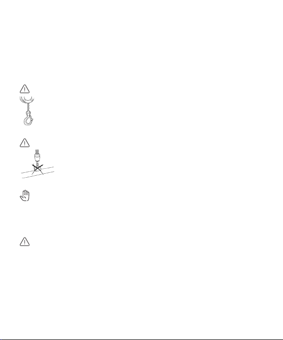
Warning
For safety reasons it is recommend to use lifting eq uipment for
lifting damped boring adaptors heavier than 18kg/40lb.
(BD x L > Ø60x800mm/Ø2,5”x31”). Lifting slings are
recommended.
Warning
Do not use a magnet when lif ting carbide reinforced
boring adaptors.
Caution
The front of the dampened boring ada ptor may be heavier because
of the integrated damped system. Check the center of gravity before
lifting.
Warning
Keep the packaging for safe storage of tools.
12

2 Product description
Example: TA61D-CY50C865W4RB (kit), includes
- adapter TB61D-CY50C865W4RB (tested adapter type 160782)
- electronic u nit: ST+:BT A 2PP (160953) / ST+:BT A 1PP (157434)
- battery: ST+ A Bat9.6Wh (157432)
The adapter is delivered in ma ny design variants based on the family,
see naming description.
Product description
Product name See marking on turn ing adaptor
Product family TA TA... Kit structure with accessor y
TB... Turning adaptor
Product type 6 5… 4C dampened bars
(sensor embedded)
6… 3C dampened bars
(sensor embedded)
Product material group 1 0... Steel
1... Carbide reinforced
Design versions
Adaptor type D D… Damped
() … Not damped
Machine side coupling CY CY… Cylindrical
13

Bar diameter 50 40, 50, 60 … and other diameter
sizes in millimeter
A... Inch descript ion, bar diameter
given in 1/16 inch
Sensor type/
signal connection C A... Unsensored
B... 1 sensor, con nector type PP x1
C... 2 sensors, connector type PP x2
D... 2 sensors, connector ty pe PP x1
Funct ional length 865 400, 500, 865...1500 and ot her, in
mm (equ al to body length for CY)
Work side
coupling interface W W... Wedge lock
S... Serration Lock
Work side
coupling interface size 4 1... 16mm, 2... 25mm, 3... 32mm, 4... 40mm
6... 60mm, 8... 80mm, 0... 100mm
Work side
coupling position R R... Right
L... Left
N... Neutral
2... 2 couplings
Area code electronics B A... G lobal
B... CE and FCC/IC (Europe, Nor th America)
C... CCC (China)
D... PSE (Japan)
E... KC (Korea)
14
F... NOM (Mexico)

3 Description
of the system
3.1 System components adaptor
Main components
Component Description
1 Turning adaptor • A turning adaptor that can mount a cutting
head with an insert and per form metal
cutting
• Consists of various models with a range of
sizes in diameter and length
• Integrated w ith sensor(s)
• Electronic unit (2), a connecting cable
(3) and a batter y (4) to form a system*
for remote monitoring of the machining
process
2 Elect ronic unit • Provide a link to the tool, through the
connecting cable (3), type PP (Push-Pull)
• Provide communication to/from t he sensor
in the tool (1)
• Provide power to the sensor and the
transmitter
• Transmit the signal to the tablet (7)
15
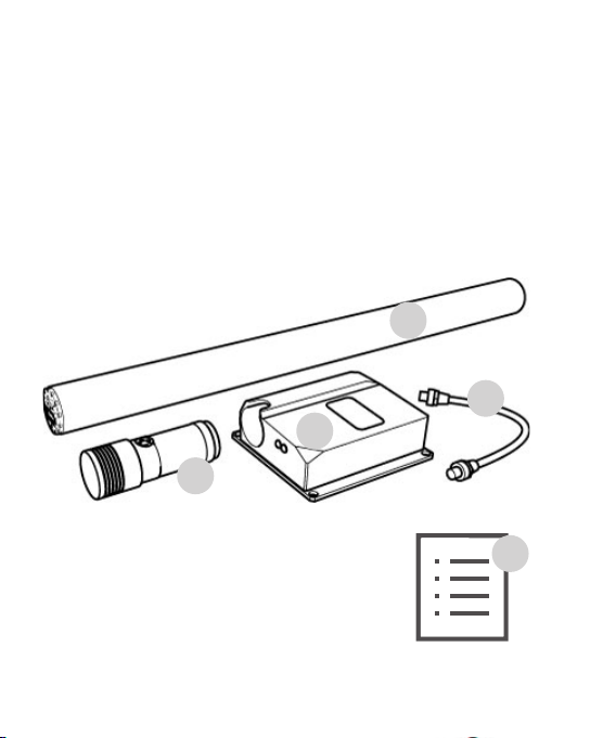
3 Connecting cable • Connecting the turning adaptor (1) to the
• Cable with PP type connectors (push-pull)
• Length 300 mm or 500mm
4 Battery • Type-A Li-ion
5 User Manuals • Silent Tools™ Plus Turning adaptor
• Silent Tools™ Elect ronic unit
• Silent Tools™ Battery
electronic u nit (2)
1
3
2
4
5
16

3.2 System components charger kit
(if ordered together)
Component Description
6 Charger • Provide charging of Type-A Li-ion battery
7 AC power adaptor • Wall adaptor
8 AC socket • Socket for EU/UK /USA
9 User Manuals • Silent Tools™ Plus Charger
• AC power
6
7
9
8
17

4 Operation
Notice
If the equipm ent is used in a manner not specif ied, the protection
provided by the equipment may be impaired.
4.1 Setting up dampened turning
adaptor
Before use
Make sure that the machine side, coupling surfaces of the tool and
tool holder are free from dust or chips. If necessar y, clean with a wet /
dry cloth.
18

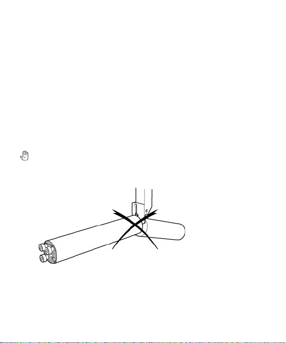
Setting up dampened adaptors
Two important factors for achieving the right dimensional tolerances
and surface finish of the component are clamping stability and
correct center height for the i nser t.
- Ensure that the length of the t urning adaptor allows for the
recommended clamping lengths. The clamping length is
recommended to be 4 times the diameter of the bar, minimum 3xd.
- Clamp in a split sleeve holder to achieve maximum contact area.
Recommended clamping tolerance is ISO H7. Recommended
bushing material w ith a minimum 45 HRC to avoid permanent
deformation.
- Never use screw s in direct contact with the bar shank as they may
damage the bar.
19

Orient tool
The tool must be rotated to the correct position (around center a xis),
for cor rect placement of the insert. This is done most easily with the
Silent Tools™ Plus sof tware. We recommend doing this when the
Silent Tools™ Plus sof tware is up and running.
A manu al lever can be used on slant bed machines.
Overhang (OHX)
The Silent Tools™ Plus Cylindrical Turning adaptor with Load Sensor
has a fixed overhang position. The sensor is placed at a specific
position inside the tool to ensure it functions as intended. Refer to t he
cata log drawing for the adaptor.
The Silent Tools™ Plus Cylindrical Turning adaptor with only Vi bration
Sensor can be used wit h overh ang bet ween OHN and OHX, as
specified in the catalog drawing for the adaptor.
20

4.2 Mounting of the electronic unit
to tool post
Mounting to tool post
4
Follow instruction in the user manual for
the electronic unit.
- Make threading holes on the machine tool holder (4).
- Fasten the electronic unit to the machine tool holder (4).
- Connect the dampened turning adaptor to the electronic unit using
connecting wire (1).
- Antenna lid (3) should be in front when fastening the electronic unit
to the tool holder.
- Risk for breakage: Make sure th at the connecting cable is not in
contact wit h machine or other par ts that may c ause damages by
running over, pinching, dragging or the like.
1
3
2
21

4.3 Connect coolant
Coolant flow
Make su re that t he coupling surfaces and threads of the fitting are
free from dust or particles. If necessary, clean with a cloth.
Thread type: G1/8 (1/8 BSP), Sealing is provided by an O-ring gasket
or a sealing washer. Torque according to fitting instructions.
Maximum pressure
The tool is design for a maximum coolant pressure of 150 PN (ba r).
Caution
Use fi ttings and tubing towards t he tool according to the maximum
coolant pressure used.
22

4.4 Connecting cables
Connect cable(s)
The adaptor sensor is connected to the radio module through a cable.
The adaptor may be equipped with one or two connector(s). The
connector is of a type PP (push -pull). Orient the cable as indicated by
the groove in the connector or N-mark. Push it in. Do not twist.
Removing cable(s)
Grasp the cable by the plug and pull out. Do not t wist.
Do not pull from the cable.
Caution
X
23

4.5 Starting up
Updating adaptor
See Use r Manual Silent Tools™ Plus Electronic Unit.
4.6 Updating the firmware
Firmware upload
Caution
Uploading f irmware can take some time. Ensure that the battery is at
least 75% charged before you star t the upload. Do not remove the
battery during t he upload process. Software is downloaded to the
tablet/PC.
When new application software is connected to the tools electronic
unit:
1) It will check if new firmware has been downloaded, compared to the
version used .
2) User will be prompted to update f irmware or postpone update.
3) When the update is complete, a message appears.
24

5 The sensors
Sensors
The Silent Tools™ Plus Cylindrical Turning adaptor can be equipped
with one or two senso r units.
Sensor 1, vibration
The vibration sensor is located just behind the cutting head interface.
It is positioned as close to the insert as possible, ensuring that the
vibr ation s that affect the sur face qualit y are monitored. The sensor
monitors vibration in three axes. The sensor monitors vibration values
from very small vibrations up to crash sit uations.
The algorithms in t he Silent Tools™ Plus softw are prov ide you w ith
analysis of the sensor information registrated during the machinging
process. The main functionsare in cut-, roughness- and vibration
monitoring. In the Silent Tools™ Plus software the algorithms are
anal yzed in more detail.
The temperature probe monitors the internal temperature in the
adaptor. Operating the adaptor within the specified temperature
range ensures optimal performance of the damping system.
The vibration sensor is calibrated from the factory.
25

Sensor 2, Load
The load sensor monitors the cutting forces and the bending of the
tool. It monitors the adaptors bending in two axes ( X and Y).
The sensor provides i nput to t he load and deflecton f unctions. It also
provides enhanced functions of the in cut and roughness functions.
More information about these funcions can be found in the Silent
Tools Plus software.
Caution
The sensor must be calibrated for best performance:
• Load function is factory calibrated, and can be f urther improved
• Deflection calibration must be done in the turning machine where
the tool is to be used
Calibration is done by a Sandvik Coromant technician or through a
specific test cut procedure. This w ill also enhance the tolerance of
the load function.
26

6 Care and transport
6.1 Transport
Shipment
When t ransport ing the product by rail, air or sea, always use the
complete original Silent Tools™ Plus packaging, transport container
and cardboard box, or equivalent , to protect against shock and
vibration.
6.2 Storage
Product
When t he adaptor is stored in a wet e nvironment, i.e. in the machine,
keep the adaptor connected to the cable to protect the con nectors.
Caution
Respect the temperature limits when storing the product, particularly
in summer if the product is inside a vehicle. Refer to sect ion “7
Technical Data” for information about temperature limits.
Keep the packaging for safe storage of the tool.
27
6.3 Cleaning and drying
Product
Use a cle an, sof t, lint-free cloth for cleaning. Electrical contact
cleaner can be used in small amounts on cable connector(s).
Cables and plugs
Keep plugs clean and dr y. Blow away any dirt lodged in the plugs of
the connecting cables.
6.4 Modify tool
Modifying of damped boring adaptor
Caution
• Shortening the adaptors with integrated electronic data collecting
system is not allowed
28

6.5 Conformity
EU
Sand vik Coromant AB declares that the product Silent Tools™ Plus
Cylindrical Turning adaptor complies to the:
Safety:
• EN 61010-1
Electromagnetic Compability (EMC):
• EN 61000-6-2
• EN 61000-6-4
Following the provisions of EU-directives:
• 2014/35/EU (low voltage)
• 2014/30/EU (EMC)
• 2011/65/EU (Rohs2)
USA/Canada
Safety:
• UL 61010-1
• CS A-C2 2.2 #61010-1
29

6.6 FCC statement, applicable in U.S.
This product has been tested and found to comply with the limits for a
Class B digit al device, pursuant to part 15 of the FCC rules.
These limits are designed to provide reasonable protection against
harmful interference in a residential installation.
This equipment generates, uses and can radiate frequency energy
and, if not installed and used in accordance with the instructions, may
cause harmful interference to radio communications.
However, there is no guarantee that interference will not occur in a
particular installation.
If this equip ment does cause harmful interference to radio or
telev ision reception, which can be determined by turning the
equipment off and on, the user is encouraged to tr y to eliminate the
interference by one or more of the following measures:
- Reorient or relocate the receiving antenna.
- Increase the separation between the equipment and the receiver.
- Connect the equipment to an outlet on a circui t different from that
to which the receiver is connected.
- Consult the dealer or an experienced radio/T V technician for help.
30

Labels
TB61D-XXXXXXXXXXX
TB61D-XXXXXXXXXXX
31

7 Warranty
Product
Sand vik Coromant AB warrants its equipment for a limited period of
two ye ars, from purchase date, provided that it is installed exactly as
defined in associated Sandvik Coromant documentation.
Failure to comply with this w ill inv alidate the Sa ndvik Coromant
warranty. Claims under warranty must be made from authorized
service/ sales personnel from Sandvik Coromant only.
For more information about Silent Tools damped adaptors please visit
www.sandvik.coromant.com (Application guide).
32

8 Technical data
Sensors
Sensor 1, Vibration Monitor vibrations from 0 -50 G
Monitor vibrations in 3 axes
(X-, Y- and Z-axis)
Temperature 0 – 120°
Sensor 2, Load Load, up to tools maximum load
(see label on tool)
Deflection in two directions
(X- and Y-axis)
Input / Output Signal
Vibration signal Signal cable, shielded 10 pin push-pull,
maximum 500 mm
Deflection signal Signal cable, shielded 10 pin push-pull,
maximum 500 mm
Input voltage 3.3v and 5.0\v
Power maximum 0.18W (3.3v) and 0.25W (5.0\v)
Operating environment IP56 according to IEC 60529
Indoor use in lathe/CNC machine,
closed or open , dry or wet machining
33

Temperature range Storage : - 40°C to +85°C
Operating: 0°C to +70°C
Relative humidity Use 10%-95%,
Storage recommended 10%- 50%
Maximum altitude 2000 m
Weight See adaptor catalog d rawing
(packaging not included).
Dimensions See adaptor catalog drawing.
34

35

Get started
To get star ted using Silent Tools™ Plus, please go to
the Sa ndvik Coromant website and activate the software using
the serial number.
www.sandvik.coromant.com/silentTools™ Plus/activate
Serial number:
Manufacturer:
Sandvik Teeness AS
Ranheimsveien 127
7053 Ranheim
Norway
92056
© AB Sandvik Coromant 2018.01
 Loading...