

Page 1

Important information to read before starting the assembly.
Keep this information for future reference.
IMPORTANT WARNINGS
Risk of serious injuries if the wall bed tips over.
!
To prevent wall bed from tipping over, mount it permanently to the wall.
Only a qualied person* must carry out the installation and any possible adjustment of the wall bed
(including disassembly). If the wall bed is not rmly mounted (anchored) to the wall, it might tip over
and cause serious injuries to the installer, users of the bed as well as the people near the bed.
The choice of wall anchoring depends on the type of wall. Use wall anchors suitable for the wall material.
* Qualied person: it is necessary to have a good understanding of the wall structure where the bed is anchored, including the positioning of the wall studs
and structural components in the case of a wood or metal structure. If you do not have the necessary skills, make sure that the installation is done by
someone who has the qualications and required knowledge. When you choose the installer, make sure to comply with all applicable regulations in the
province, state or country where the furniture is installed.
Every time the bed is used, the owner should make sure that the anchors are strong and show no signs of weakening (for example if you feel that the
anchor screws are moving when pulling on the cabinet of the bed). Do not use the wall bed if the cabinet moves and do not open the bed if you are not
sure that it is rmly attached to the wall, because it could tip over causing serious injuries. When in doubt about the anchoring, please stop using the
bed immediately and have it inspected by a professional* or contact us at 1-888-823-7827.
is released from any responsibility and will void the warranty if the installation or the anchoring is not done according to the
recommendations included in this instruction manual. and its distributors (and their respective ocers, directors, agents and servants)
shall not be liable or obligated in any manner for any direct, punitive, exemplary, special, indirect, incidental or consequential damages of any
kind, regardless of the form of action, whether in contract, tort, negligence, strict product liability or otherwise, arising out of or in connection
with improper anchoring of the bed or non-compliance to the anchoring procedure of this document.
IMPORTANT: BEFORE STARTING ASSEMBLY
Be sure to conrm the following information:
1. The installer has the qualications * and required knowledge.
2. Only wall anchor screws for wood-frame walls are provided with this bed. See anchor requirements and installation notes provided
in the instruction manual, according to the type of wall, and use the appropriate anchors such as described in this manual.
3. Your bed can hold a maximum distributed weight of 1000 lb (455 kg), including the weight of the mattress.
4. Maximum thickness of mattress: 12 in (30.5 cm), and must stand in vertical position without sagging.
5. The bed will not stay open without the weight of the mattress which must be between: 60 lb (27 kg) and 90 lb (41 kg).
6. Minimum ceiling height requirements for installation: 88.75 in (2.25 m).
7. It is recommended to assess the structural integrity of the oor and wall and to make sure that the wall anchoring devices can withstand the
forces generated. More specically, before installing the wall bed, it is necessary to verify that the oor and the wall on which you want to install
the bed are at and have no structural damage that could aect the installation of the wall bed or its anchoring to the wall. Do not install the bed
on weakened or rotten structures.
8. It is necessary to ensure that wall anchors of the bed can withstand forces generated. The value of the holding power (Fh) of each anchor should
be 630 Newtons (142 lbf).
If the wall bed is not installed properly, the latter might close unexpectedly or could open involuntarily.
In addition, if the wall bed is installed incorrectly, one of its structural components may break and fall o.
Page 2

FOR ANY
PROBLEM
OR
INFORMATION
THANK YOU FOR CHOOSING A PRODUCT.
YOUR TOTAL SATISFACTION IS OUR #1 PRIORITY.
Customer Service and warranty information
Please have your assembly instruction manual on hand when you call. products are warranted to the original purchaser against defects in material or
workmanship in the furniture. Defects as mentioned in this warranty refer to any imperfections which may impair the use of the product. Our warranty is expressly
limited to the replacement of furniture parts and components for ten years following the date of purchase. will replace any part that is defective. This warranty
applies under conditions of normal use. Our furniture products are not intended for outdoor use. The warranty does not cover defects caused by improper assembly
or disassembly, defects occurring after purchase due to product modications, intentional damage, accident, misuse, exposure to the elements and labor or assembly
costs. reserves the right to request proof of purchase to document a warranty claim. In no event shall be liable for incidental or consequent damages
resulting from the misuse of the product.
This warranty is not transferable and is valid only in Canada and the United States excluding Alaska, Hawaii and Puerto Rico.
Page 3

PAR TS
CODE QTY CODE QTY CODE QTY CODE QT Y
30 1
60 2
81 1
87 1
31 1
40 1
41 1
61 1
63 1
70 2
PROBLEMS OR INFORMATION
41
63
60
61
60
87
31
00
82 1
83 1
84 1
82
MO-7493
MO-7493 2
Part number on the top or on edge
87
41
30
84
82
83
70
31
83
3
Page 4

HARDWARE IN BOX 1
CODE QT É CODE QTÉ CODE QTÉ COD E QTÉ
1
2 lights
Power supply
Switch
2 Extensions
4
2
3/8” (10 mm)
5/8” (15 mm)
12
1
8
3
16
4
4
16
3/4” (18 mm)
2
4
1” (25 mm)
2
4
Outside diameter
3/4” (19 mm)
1
2
4
1
1
LEG WARNING STICKER
1
Do not use the
screws included
HARDWARE IN BOX 3
CODE QT É CODE QTÉ CODE QT É CODE QTÉ
1
1
2
1
12
4
5/8”
(16 mm)
14
2
1
1
1
2
MODEL
INSTALLATION BY A QUALIFIED PERSON*
Only a qualied person* must carry out the installation and any possible adjustment of the wall bed (including disassembly).
BESTAR is released from any responsibility if bed is not secured to the wall according to the recommendations included in this instruction leaet.
Keep proof of professional service use for the installation of your bed. These may be required for the application of the product warranty.
IMPORTANT WARNINGS:
RISK RESULTING FROM AN INCORRECT INSTALLATION
Only a qualied person * must carry out the installation and
!
any possible adjustment of the wall bed (including disassembly).
IMPROPER INSTALLATION OF THE WALL BED (RETRACTABLE BED) MAY CAUSE SERIOUS INJURIES TO THE INSTALLER, USERS OF THE BED AS WELL
AS THE PEOPLE NEAR THE BED. MORE SPECIFICALLY, IF THE WALL BED IS INSTALLED INCORRECTLY, IT COULD TIP, CLOSE UNEXPECTEDLY or
UNINTENTIONALLY WHEN IT IS OPEN, or OPEN UNEXPECTEDLY or UNINTENTIONALLY WHEN IT IS CLOSED, or ONE OF ITS STRUCTURAL
COMPONENTS MAY BREAK AND FALL OFF.
If you do not have the necessary skills*, make sure that the installation is done by a professional*. A good understanding of the wall structure
where the bed is anchored is necessary, including the positioning of the wall studs and structural components in the case of a wood or metal
structure. When you choose a professional for the installation, ensure to observe all applicable laws.
BESTAR IS RELEASED FROM ANY RESPONSIBILITY IF THE INSTALLATION OR THE ANCHORING IS NOT DONE ACCORDING TO THE
RECOMMENDATIONS INCLUDED IN THIS INSTRUCTION MANUAL.
BESTAR AND ITS DISTRIBUTORS (AND THEIR RESPECTIVE OFFICERS, DIRECTORS, AGENTS AND SERVANTS) SHALL NOT BE LIABLE OR
OBLIGATED IN ANY MANNER FOR ANY DIRECT, PUNITIVE, EXEMPLARY, SPECIAL, INDIRECT, INCIDENTAL OR CONSEQUENTIAL DAMAGES
OF ANY KIND, REGARDLESS OF THE FORM OF ACTION, WHETHER IN CONTRACT, TORT, NEGLIGENCE, STRICT PRODUCT LIABILITY OR
OTHERWISE, ARISING OUT OF OR IN CONNECTION WITH IMPROPER ANCHORING OF THE BED OR NON-COMPLIANCE TO THE ANCHORING
PROCEDURE OF THIS DOCUMENT.
DETERMINE THE FINAL LOCATION OF YOUR WALL BED (ON THE WALL AND ON THE FLOOR).
It is recommended to assess the structural integrity of the oor and wall and to make sure that the wall anchoring devices can withstand the forces
generated. More specically, before installing the wall bed, it is necessary to verify that the oor and the wall on which you want to install the bed
are at and have no structural damage that could aect the installation of the wall bed or its anchoring to the wall. Do not install the bed on weakened
or rotten structures.
HOLDING POWER
The value of the holding power (Fh) of each anchor should be 400 Newtons (90 Lb) if the wall bed is properly installed. At each use, the owner of the
wall bed should make sure that the anchors are strong and show no signs of weakening (for example if you feel that the anchor screws are moving
when pulling on the cabinet of the bed). Do not use the wall bed if the cabinet moves and do not open the bed if you are not sure that it is rmly
attached to the wall, because it could tip over causing serious injuries. When in doubt about the anchoring, please stop using the bed immediately
and have it inspected by a professional* or contact us at 1-888-823-7827.
IMPORTANT: BEFORE STARTING ASSEMBLY
Be sure to conrm the following information:
1. The installer has the qualications * and required knowledge.
2. Only wall anchor screws for wood-frame walls are provided with this bed. See anchor requirements and installation notes provided
in the instruction manual, according to the type of wall, and use the appropriate anchors such as described in this manual.
3. Your bed can hold a maximum distributed weight of 1000 lb (455 Kg), including the weight of the mattress.
4. Maximum thickness of mattress: 10 in (25.4 cm), and must stand in vertical position without sagging.
5. The bed will not stay open without the weight of the mattress which must be between: 45Lb (20 Kg) and 90 Lb (41 Kg).
6. Minimum ceiling height requirements for installation: 91.5 in (2.32 m).
* A CERTIFIED CONSTRUCTION PROFESSIONAL, IN COMPLIANCE WITH APPLICABLE REGULATIONS IN THE PROVINCE, STATE,
OR COUNTRY WHERE THE FURNITURE IS INSTALLED.
00000-0000
1
1
2
PRODUCTION 0000
12
8
1 3/4” (44 mm)
3
2 3/4” (70 mm)
To better serve you!
Pour mieux vous servir!
Model / Modèle:
Production Number
Numéro de production:
Customer Service
Service à la clientèle
For future reference and to better serve you,
please complete and apply the self-adhesive
sticker in an accessible space such as the
back of part 60.
PRODUCTION 0000
5/8”
(16 mm)
4
8
4
Page 5

ACTUAL SIZE
CODE
QTÉ
CODE
QTÉ
16
4
12
8
12
5/8” (16 mm)
5/8” (16 mm)
5/8” (16 mm)
1 3/4” (44 mm)
2” (51 mm)
10
2
4
48
8
1/2” (13 mm)
3/4” (19 mm)
1/2” (13 mm)
2” (51 mm)
5
6
2
1” (25 mm)
3/4” (19 mm)
4
3/8” (10 mm)
6
2 3/4” (70 mm)
6
3 1/2” (89 mm)
5
Page 6

Pull out
B
Turn
A
IMPORTANT NOTICE
Main hardware system. Installation steps.
1
H-36
Push down
Proper position
Main hardware system. Assembly steps.
1
2
Insert
REQUIRED TOOLS
A
3
Tighten
Arrow
2
H-03
Insert the cam with the arrow pointing
toward the hole in the edge.
B
Make sure to properly tighten each cam to ensure
furniture solidity. Otherwise, parts could be damaged
or the user could be injured.
Important
How to remove a misplaced assembly bolt (H-36).
Three people are required to
assemble and move this furniture.
When you have completed the assembly
of your new furniture, install plastic caps
CA-99
23/32”
18mm
CA-100
3/32”
2,5mm
H-03
When you have completed
the assembly of your new
furniture, install self-adhesive
caps on unused holes.
VC-204
CA-77
3/8”
10mm
Unused holes
CA-1014
REQUIRED TOOLS
#3
1/4” (7 mm)
6
Page 7

KI-932-H
Hardware installation & assembly
1
Sequence of assembly
Parts:
+
41
EQ-1035
IMPORTANT
Place boxes under parts during
the assembly to avoid damages.
EQ-1035
IMPORTANT
The EQ-1035 bracket is designed
to allow the bed structure to adjust
up to 5/8 in. (15 mm) for the compaction
+
87
of a carpet for example. (See the wall
anchoring step)
Tag visible
on this side
5/8 po (15 mm)
5/8 po (15 mm)
87
GO-796
41
UNDERSIDE
H-36
Use a screwdriver for these screws
87
KI-932-I
41
TOP
1
Code
Qty
EQ-1035
x 3
GO-796
x 4
H-03
x 4
H-36
x 4
KI-932-H
x 12
3/4” (18 mm)
KI-932-I
x 6
5/8” (15 mm)
VF-1013
x 6
Use a screwdriver for these screws
1” (25 mm)
VF-1013
7
Page 8

Hardware installation
PA-844
KI-932-H
KI-932-H
2
Assembling sequence
Parts:
30
+
KI-985-D+KI-985-M
31
+
KI-985-C+KI-985-M
KI-985-M
KI-932-I
RO-994
KI-985-D
30
KI-932-H
2
Code
Qty
8
KI-985-Q
KI-985-M
KI-985-C
KI-985-C
x 1
KI-932-I
RO-994
KI-932-H
KI-985-D
x 1
KI-985-M
x 12
5/8” (16 mm)
KI-985-Q
x 1
31
PA-844
x 4
1” (25 mm)
RO-994
x 4
KI-932-I
x 4
5/8” (16 mm)
KI-932-H
3/4” (18 mm)
x 4
Page 9

Hardware installation & assembly
3
Assembling sequence
Parts:
7030 31 41 8440
GO-796
VC-204
H-03
31
84
70
40
30
3
Code
Qty
GO-796
x 10
VC-204
x 8
2” (50 mm)
H-03
x 4
9
Page 10

Hardware installation & assembly
4
Adhere the RU-420 into the groove
and glue the wires of the switch on it.
AC-1009-D
AC-1009-D
AC-1009-A
Switch can be installed
on left side or on right
side.
4
Code
Qty
10
AC-1009-A
x 2
AC-1009-B
x 1
AC-1009-C
x 1
AC-1009-D
x 2
AC-1009-C
AC-1009-B
RU-420
x 1
Page 11

Hardware installation & assembly
5
Assembling sequence
Parts:
MO-7943
+ Wire + RU-420
SU-1007
MO-7493
5
Code
Qty
VR-211
x 4
VR-211
3/4” (19 mm)
SU-1007
x 2
11
Page 12
WALL ANCHORING REQUIREMENTS
& INSTALLATION RECOMMENDATIONS
Important information to read before starting the assembly.
Keep this information for future reference.
IMPORTANT WARNINGS
Risk of serious injuries if the wall bed tips over.
To prevent wall bed from tipping over, mount it permanently to the wall.
Only a qualied person* must carry out the installation and any possible adjustment of the wall bed
(including disassembly). If the wall bed is not rmly mounted (anchored) to the wall, it might tip over
and cause serious injuries to the installer, users of the bed as well as the people near the bed.
The choice of wall anchoring depends on the type of wall. Use wall anchors suitable for the wall material.
* Qualied person: it is necessary to have a good understanding of the wall structure where the bed is anchored, including the positioning of the
wall studs and structural components in the case of a wood or metal structure. If you do not have the necessary skills, make sure that the wall
anchoring is done by someone who has the qualications and required knowledge. When you choose the installer, make sure to comply with
all applicable regulations in the province, state or country where the furniture is installed.
!
OTHER TYPES OF WALLS
If the structure of the wall is not wood, metal or masonry: The service of
a professional ** would be required for the wall anchoring. BESTAR is released from
any responsibility if wall anchoring of this furniture is not done by a professional.
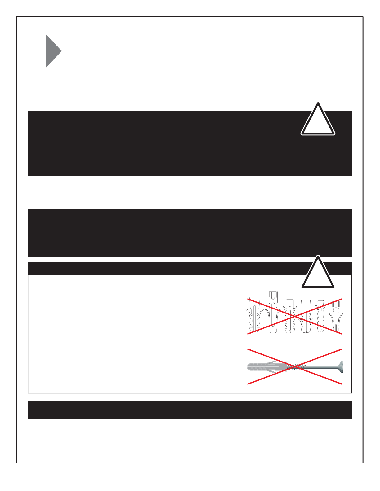
IMPORTANT WARNINGS
INSTALLATION AND APPROPRIATE HARDWARE
Using appropriate hardware, all the anchor screws of the wall bed must be rmly
secured to the wood or metal studs, the structural components, or a masonry wall.
Only wall anchor screws for wood-frame walls are provided with this bed.
NEVER USE DRYWALL ANCHOR SCREWS OR SECURE THE BED TO DRYWALL
See wall anchoring requirements and installation notes provided in the
instruction manual, according to the type of wall, and use the appropriate
anchors such as described in this manual.
NUMBER OF SCREWS NEEDED
Two (2) screws are required for each anchor point. Three (3) wall anchor points
are necessary for the proper installation of the wall bed. So you need a total
of six (6) wall anchor screws.
THE SCREWS MUST BE VERY WELL ANCHORED TO THE STRUCTURAL
COMPONENTS OF THE WALL.
!
** A CERTIFIED CONSTRUCTION PROFESSIONAL, IN COMPLIANCE WITH APPLICABLE REGULATIONS IN THE PROVINCE, STATE,
OR COUNTRY WHERE THE FURNITURE IS INSTALLED.
12
Page 13

WALL ANCHORING INSTRUCTIONS
INSTALLATION RECOMMENDATIONS — WOOD STUDS
WALL COMPOSITION
Wood studs
(50 mm)
2”
87
ACCORDING TO YOUR WALL TYPE AND COMPOSITION, YOUR PROFESSIONAL INSTALLER SHOULD APPROVE
THE CHOICE OF ANCHOR SCREWS AND SELECT, IF REQUIRED, MORE APPROPRIATE ANCHORING DEVICES.
HARDWARE
“COARSE THREAD SCREWS No #10”
VR-1047 BT-1048
6 screws included Robertson (square-tip) bit included
REQUIRED TOOLS
3 1/2“ (89 mm)
Wood drill
bit 1/4” (6 mm)
6
Stud
nder
13
Page 14

WALL ANCHORING INSTRUCTIONS
INSTALLATION RECOMMENDATIONS - WOOD STUDS
Determine the position of the bed in the room.
Locate and mark the positioning
21
of 3 studs using a stud nder.
Put the bed back in its place. Level by adjusting
3
Move the bed if necessary, then cut and
remove the oor trim.
5
Line up plywood part #87 on the wall and mark the middle of the studs on the plywood, then pre-drill
part #87 with 2 pilot holes of 1/4” (6 mm) diameter per stud, 2” (50 mm) apart vertically (6 holes in total).
DO NOT DRILL HOLES INTO THE WOOD STUDS.
4
the legs PA-844 previously installed. If you install
the bed on a carpet, you must raise the bed by
an extra 3/8“ (10 mm).
87
PA-844
14
87
87
2” (50 mm)
1/4”
(6 mm)
2” (50 mm)
1/4”
(6 mm)
Page 15

WALL ANCHORING INSTRUCTIONS
INSTALLATION RECOMMENDATIONS - WOOD STUDS
IMPORTANT WARNINGS
INSTALLATION AND APPROPRIATE HARDWARE
Using appropriate hardware, all the anchor screws of the wall bed must be rmly
secured to the wood or metal studs, the structural components, or a masonry wall.
Only wall anchor screws for wood-frame walls are provided with this bed.
NEVER USE DRYWALL ANCHOR SCREWS OR SECURE THE BED TO DRYWALL
See wall anchoring requirements and installation notes provided in the
instruction manual, according to the type of wall, and use the appropriate
anchors such as described in this manual.
NUMBER OF SCREWS NEEDED
Two (2) screws are required for each anchor point. Three (3) wall anchor points
are necessary for the proper installation of the wall bed. So you need a total
of six (6) wall anchor screws.
THE SCREWS MUST BE VERY WELL ANCHORED TO THE STRUCTURAL
COMPONENTS OF THE WALL.
6
Put the wood screws #10 x 3 1/2” (89 mm) through the holes of part #87 and screw into the center of the studs
until the plywood is tight against the wall. USE AN ELECTRIC SCREWDRIVER WITH AN ADJUSTABLE TENSION
CLUTCH THAT HELPS PREVENT OVER-TIGHTENING AND STRIPPING.
!
87
Drywall
2” (50 mm) minimum
Wood stud
15
Page 16

WALL ANCHORING INSTRUCTIONS
INSTALLATION RECOMMENDATIONS — MASONRY
WALL COMPOSITION
Masonry
87
ACCORDING TO YOUR WALL TYPE AND COMPOSITION, YOUR PROFESSIONAL INSTALLER SHOULD APPROVE
THE CHOICE OF ANCHOR SCREWS AND SELECT, IF REQUIRED, MORE APPROPRIATE ANCHORING DEVICES.
HARDWARE
“CONCRETE SCREWS 3/16” (5 mm) diameter X APPROPRIATE LENGTH”
NOT included
REQUIRED TOOLS
16
Hammer drill
Masonry drill bit
5/32” (4 mm)
Diameter
6
Wood drill bit
1/4” (6 mm)
Diameter
Page 17

WALL ANCHORING INSTRUCTIONS
INSTALLATION RECOMMENDATIONS — MASONRY
1
Determine and mark the position
of the bed in the room.
Put the bed back in its place. Level by adjusting
2
Move the bed if necessary, then cut
and remove the oor trim.
4
Pre-drill the piece of plywood #87 with 6 pilot holes of 1/4” (6mm) diameter distributed horizontally in order to cover
the width of the anchoring section. With the bed in position, mark the position of the 6 holes on the masonry wall.
3
the legs PA-844 previously installed. If you install
the bed on a carpet, you must raise the bed by
an extra 3/8” (10 mm).
PA-844
87
1/4”
(6 mm)
87
1/4” (6 mm)
87
Locate and mark
the positioning
of the 6 anchor
points.
17
Page 18

WALL ANCHORING INSTRUCTIONS
INSTALLATION RECOMMENDATIONS — MASONRY
5
Move the bed again.
6
Using a 5/32” (4 mm) diameter masonry bit, drill into the drywall
and masonry (a hammer drill is required).
Masonry
IMPORTANT WARNINGS
INSTALLATION AND APPROPRIATE HARDWARE
Using appropriate hardware, all the anchor screws of the wall bed must be rmly
secured to the wood or metal studs, the structural components, or a masonry wall.
Only wall anchor screws for wood-frame walls are provided with this bed.
Drywall
Wood
!
NEVER USE DRYWALL ANCHOR SCREWS OR SECURE THE BED TO DRYWALL
See wall anchoring requirements and installation notes provided in the
instruction manual, according to the type of wall, and use the appropriate
anchors such as described in this manual.
NUMBER OF SCREWS NEEDED
Two (2) screws are required for each anchor point. Three (3) wall anchor points
are necessary for the proper installation of the wall bed. So you need a total
of six (6) wall anchor screws.
THE SCREWS MUST BE VERY WELL ANCHORED TO THE STRUCTURAL
COMPONENTS OF THE WALL.
7
Put the bed back in its place.
Put the CONCRETE SCREWS 3/16"
(5mm) diameter X APPROPRIATE
LENGTH into the holes of part #87
and screw the bed onto the masonry
wall until tight against the wall.
Screw must be at least 1 1/4” (32mm)
deep into masonry.
USE AN ELECTRIC SCREWDRIVER
WITH AN ADJUSTABLE TENSION
CLUTCH THAT HELPS PREVENT
OVER-TIGHTENING AND STRIPPING.
87
Wood
Drywall
Minimum 1 1/4” (32mm)
Maximum 1 3/4” (44 mm)
Masonry
18
Page 19

WALL ANCHORING INSTRUCTIONS
INSTALLATION RECOMMENDATIONS — METAL STUDS
WALL COMPOSITION
Metal studs
(50 mm)
2 po
ACCORDING TO YOUR WALL TYPE AND COMPOSITION, YOUR PROFESSIONAL INSTALLER SHOULD APPROVE
THE CHOICE OF ANCHOR SCREWS AND SELECT, IF REQUIRED, MORE APPROPRIATE ANCHORING DEVICES.
HARDWARE
“Adjustable wall anchor” Snaptoggle® *
SCREW (10-24) X APPROPRIATE LENGTH
NOT includedWall anchoring NOT included
REQUIRED TOOLS
87
6
Drill bit for metal
Hammer drill
*Patented under one or more of the following U. S. Patent Nos. : 5,938,385; 6,161,999; 7,144,212; 7,320,569; and foreign counterparts thereof. Others patents pending.
TOGGLER and t ypeface, symbol, TA, TB, TC, TH, SP, ALLIGATOR, ALLIGATOR design, SNAPTOGGLE, SnapSkru, and High-Performance Anchors
are worldwide registered trademarks of Mechanical Plastics Corp.
1/2” (13 mm)
diameter
Wood drill bit
1/4” (6 mm)
diameter
Stud
nder
19
Page 20

WALL ANCHORING INSTRUCTIONS
INSTALLATION RECOMMENDATIONS — METAL STUDS
1
Determine the position of the bed in the room.
Locate and mark the positioning of 3 studs
2
by using a stud nder.
Put the bed back in its place. Level by adjusting
3
Move the bed if necessary, then cut
and remove the oor trim.
5
Line up plywood part #87 on the wall and mark the middle of the studs on the plywood, then pre-drill
part #87 with 2 pilot holes of 1/4” (6 mm) diameter per stud, 2” (50 mm) apart vertically (6 holes in total).
With the bed in position, mark the positioning of the 6 holes on the drywall.
4
the legs PA-844 previously installed. If you install
the bed on a carpet, you must raise the bed by
an extra 3/8” (10 mm).
87
PA-844
20
87
87
2” (50 mm)
1/4”
(6 mm)
2” (50 mm)
1/4” (6 mm)
Page 21

WALL ANCHORING INSTRUCTIONS
INSTALLATION RECOMMENDATIONS — METAL STUDS
6
Move the bed again.
7
Using a 1/2” (13 mm) diameter metal bit, drill into the drywall
and the metal studs.
Metal
studs
Drywall
IMPORTANT WARNINGS
INSTALLATION AND APPROPRIATE HARDWARE
Using appropriate hardware, all the anchor screws of the wall bed must be rmly
secured to the wood or metal studs, the structural components, or a masonry wall.
Only wall anchor screws for wood-frame walls are provided with this bed.
!
NEVER USE DRYWALL ANCHOR SCREWS OR SECURE THE BED TO DRYWALL
See wall anchoring requirements and installation notes provided in the
instruction manual, according to the type of wall, and use the appropriate
anchors such as described in this manual.
NUMBER OF SCREWS NEEDED
Two (2) screws are required for each anchor point. Three (3) wall anchor points
are necessary for the proper installation of the wall bed. So you need a total
of six (6) wall anchor screws.
THE SCREWS MUST BE VERY WELL ANCHORED TO THE STRUCTURAL
COMPONENTS OF THE WALL.
21
Page 22

WALL ANCHORING INSTRUCTIONS
INSTALLATION RECOMMENDATIONS — METAL STUDS
Slide the metal channel of the anchor through the hole in the wall, hold the straps together and pull toward you
8
until the channel rests behind the wall. Slide the cap along the straps until it is ush with the wall. Snap o the straps.
Put the bed back in its place.
9
Insert the screw (10-24) X APPROPRIATE LENGTH
into the hole of part #87 and screw the bed until
snug against the wall.
87
Metal
studs
Drywall
OTHER TYPES OF WALLS
If the structure of the wall is not wood, metal or masonry: The service of
a professional ** would be required for the wall anchoring. BESTAR is released from
any responsibility if wall anchoring of this furniture is not done by a professional.
** A CERTIFIED CONSTRUCTION PROFESSIONAL, IN COMPLIANCE WITH APPLICABLE REGULATIONS IN THE PROVINCE, STATE,
OR COUNTRY WHERE THE FURNITURE IS INSTALLED.
22
Page 23

Hardware installation & assembly
7
Assembling sequence
Parts:
+
83 82
CH-838
PO-1036
VF-1065
7
Code
Qty
CH-838
x 8
PO-1036
x 2
3/8 " (10 mm)
VF-1065
x 4
23
Page 24

Hardware installation & assembly
8
VC-204
70
Choose the side according to your color preference
8
24
Code
Qty
2” (50 mm)
VC-204
x 4
Page 25

Hardware installation & assembly
9
KI-985-N
KI-985-N
KI-985-O
KI-985-F
KI-985-B
KI-985-N
KI-985-B
KI-985-A
KI-985-F
9
Code
Qty
KI-985-A
x 1
KI-985-B
x 1
KI-985-F
x 2
KI-985-N
x 8
1 3/4” (44 mm)
KI-985-F
2 3/4” (70 mm)
KI-985-O
x 3
25
Page 26
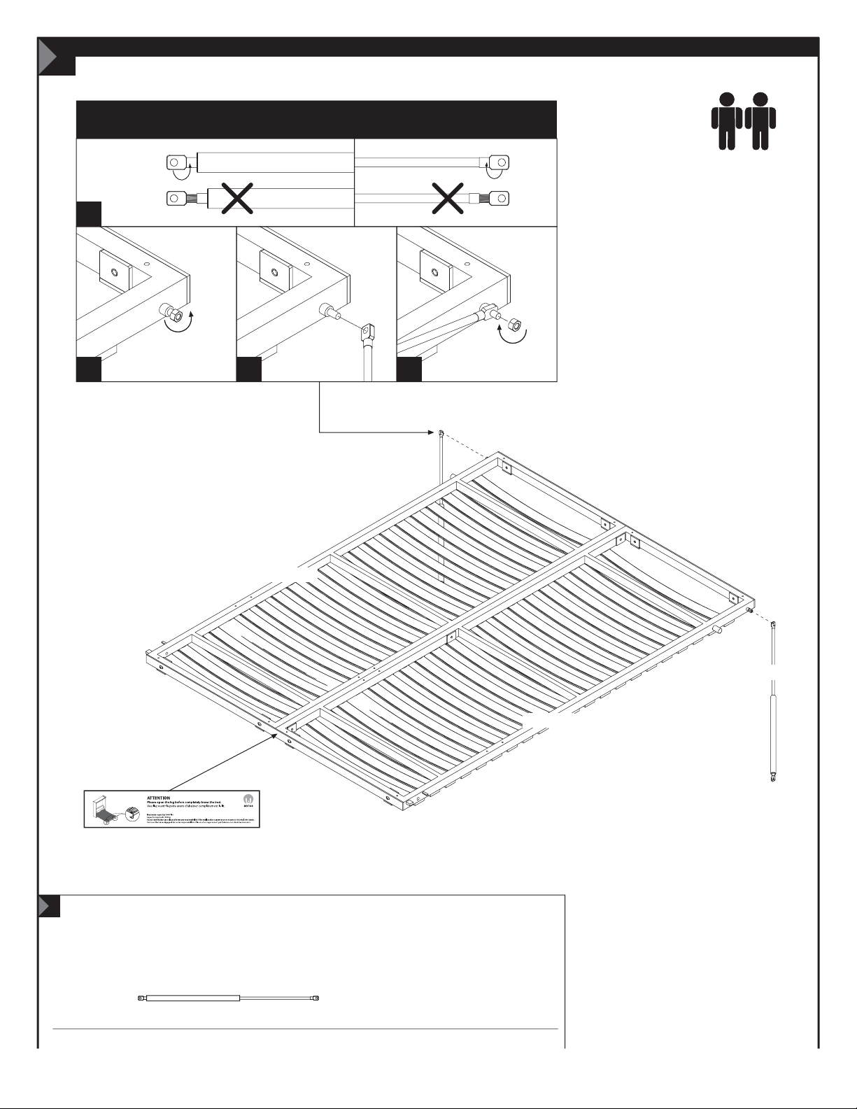
Hardware installation and assembly
10
SCREW PROPERLY BOTH ENDS OF THE CYLINDER
KI-985-J
1
2
3 4
KI-985-J
KI-985-B
KI-985-J
KI-985-A
10
26
Code
Qty
LEG WARNING STICKER
KI-985-J
x 2 x 1
Page 27

Hardware installation & assembly
IMPORTANT
1. Place the bearings equally on each side before attaching them.
2. Position the bearing support in such a way as to lock. (Image 1)
3. Firmly tighten the bearing support.
11
KI-985-L
INSERT MATTRESS SUPPORT
KI-985-E
VIS
Image 1
KI-985-P
BOULON
KI-985-L
KI-985-A
KI-985-B
KI-985-A
KI-985-B
FRONT VIEW
KI-985-P
11
Code
Qty
5/8” (16 mm)
KI-985-L
x 4
KI-985-P
x 2
KI-985-E
x 2
27
Page 28
Hardware installation & assembly
IMPORTANT
Take note that after the installation of the pistons, it will be very
dicult to open the bed. Follow the steps until the end, put the
mattress on, and the bed will open without eort.
12
INSERT CYLINDER ON ITS SUPPORT ROD
KI-985 must be completely tightened
KI-985-J
KI-985-J
KI-985-C
KI-985-D
Page 29

Hardware installation & assembly
13
IMPORTANT
Use one of the cardboard corner pieces from
packaging or similar object to keep the bed
in semi-closed position for the following steps.
29
Page 30

Hardware installation & assembly
14
Assembling sequence
Parts:
+
41
81
1
GO-796
41
81
VR-462
14
30
Code
Qty
VR-462
x 5
GO-796
x 2
Page 31

Hardware installation & assembly
15
KI-985-H
KI-985-I
15
Code
Qty
KI-985-H
KI-985-I
1
KI-985-G
x 1
2
KI-985-H
x 1
KI-985-H
KI-985-I
KI-985-I
x 1
KI-985-H
KI-985-I
3
Front
view
Washer
31
Page 32

Hardware installation & assembly
3500-400350
16
Assembling sequence
Parts:
60 60 61 63
KI-985-K
63
61
2x
60
VM-601
16
Code
Qty
32
1/2” (13 mm)
3500-400350
x 40
EQ-143
x 4
KI-985-K
x 16
Do not use the
screws included
PO-1040
x 1
63
P0-1040
3/4 ” (20 mm)
VM-601
x 2
Page 33

Hardware installation & assembly
IMPORTANT
Rotate the leg toward the interior.
17
33
Page 34

Hardware installation & assembly
KI-985-A
18
Assembling sequence
Parts:
KI-985-A
Use one of the cardboard corner pieces from
packaging or similar object to keep the bed
in semi-closed position for the installation
of the facades.
KI-985-B
IMPORTANT
60
+
60 61
KI-985-A
61
KI-985-B
34
60
61
60
Page 35

Hardware installation & assembly
19
Assembling sequence
Parts:
KI-985-A
KI-985-B
63
+
63
60
63
61
60
63
60
61
60
35
Page 36

20
ATTENTION
Please ip down the leg before
completely lowering the bed.
IMPORTANT
Adjust and centre facades before
screwing them to the metal bed frame
Hardware installation & assembly
IMPORTANT
20
1-
KI-985-R
2-
VR-215
KI-985-S
VR-215
3500-400350
OTHER IMPORTANT
WARNINGS
!
• After you have nished assembling your wall
bed, close it. If the gap around the bed is
uneven, push or gently kick the base of the
CABINET on the side with the NARROWEST
gap until desired gap is obtained.
• After you have nished assembling your wall
bed, please keep the assembly book by placing
it under the mattress, in the frame of the mobile
part of the bed.
• Avoid placing the furniture in the sunlight
or near a source of heat. Use a soft dry cloth
for dusting. To clean heavy dirt, use a cloth
dipped in a solution of mild detergent and
water. Avoid leaving wet objects on the
surface or using commercial chemical
cleaning products.
2” (51 mm)
Code
Qty
36
VR-215
x 8
KI-985-R
x 4
KI-985-S
x 8
1/2” (13 mm)
3500-400350
x 8
Page 37

IMPORTANT NOTICE
IMPORTANT
MINIMUM AND MAXIMUM WEIGHT OF THE MATTRESS
The weight of the mattress must be between: 45 Lb (20 Kg) and 90 Lb (41 Kg).
Please make sure that the size of your mattress is suitable for
your wall bed (60 x 80” (1524 x 2032 mm) / Queen or 54 x 75”
(1371 x 1905 mm) / Double). Whether foam or spring, the mattress
must have a maximum thickness of 12” (305 mm) / Queen,
10” (254 mm) / Double, and must stand in vertical position
without sagging.
OTHER IMPORTANT WARNINGS
!
• Never close the bed with a person on the mattress,
this could cause serious injuries and damage the
bed mechanism.
• Never jump on the bed or leave a young child playing
alone in the bed. This could cause the person to fall
and could also damage the bed mechanism.
• Never close the bed with the lights on. Do not leave
an electric blanket or any other sources of heat inside
the closed cabinet. This could cause a re.
• Do not leave anything on the bed which could prevent
to close it properly (pillows, decorative cushion, plush
toys, etc.). This can cause an unexpected or unintended
opening of the bed that can cause serious injuries
to people in the vicinity.
• Your bed can hold a maximum weight (static and
uniformly distributed) of 1000 lb (455 Kg), including
the weight of the mattress.
AND ITS DISTRIBUTORS (AND THEIR RESPECTIVE OFFICERS, DIRECTORS, AGENTS AND SERVANTS) SHALL NOT BE LIABLE OR
OBLIGATED IN ANY MANNER FOR ANY DIRECT, PUNITIVE, EXEMPLARY, SPECIAL, INDIRECT, INCIDENTAL OR CONSEQUENTIAL DAMAGES
OF ANY KIND, REGARDLESS OF THE FORM OF ACTION, WHETHER IN CONTRACT, TORT, NEGLIGENCE, STRICT PRODUCT LIABILITY
OR OTHERWISE, ARISING OUT OF OR IN CONNECTION WITH IMPROPER ANCHORING OF THE BED OR NON-COMPLIANCE TO THE
ANCHORING PROCEDURE OF THIS DOCUMENT.
• Do not apply any weight on the facades, such as frames,
shelves, hooks.
• The wall bed must always rest on its legs when it is
open. If this is not the case, you could damage the bed
mechanism and/or the door of the bed and/or the oor.
Before closing the bed, always ip the leg inward to
not damage the furniture.
• If the bed mechanism or a panel is damaged for any
reason, please stop using the bed and contact us at
1-888-823-7827 to get the instructions and the parts
required for the repair (if possible). Do not continue to
use a damaged bed and don't try to x it yourself without
instructions from Bestar. This could cause a malfunction,
an unexpected or involuntary opening or closing or a
collapse of its structure, which can cause serious injuries
to people in the vicinity.
37
Page 38

DISASSEMBLY
Important information to read before starting the disassembly.
Keep this information for future reference.
IMPORTANT WARNINGS
Bed may tip over and you may be seriously injured if you don't follow these instructions.
• Only a qualied person * must proceed with the disassembly of the wall bed, as well as the
reinstallation and any possible adjustment.
• Improper disassembly of the wall bed may cause serious injuries to the installer as well
as the people near the bed.
THE BED SHOULD REMAIN ANCHORED TO THE WALL FOR THE FOLLOWING STEPS (1 TO 9).
* Qualied person: It is necessary to have a good understanding of the wall anchors that were used during the original installation on your wall
structure of wood, metal, masonry or any other type of wall. If you don't have the necessary skills, make sure that the disassembly is done by
someone who has the qualications and required knowledge, and that he or she follows the required steps. When you choose the installer, make
sure to comply with all applicable regulations in the province, state or country where the furniture is installed.
is released from any responsibility and will void the warranty if the disassembly is not performed according to the instructions
in this manual. and its distributors (and their respective ocers, directors, agents and servants) shall not be liable or obligated
in any manner for any direct, punitive, exemplary, special, indirect, incidental or consequential damages of any kind, regardless of the
form of action, whether in contract, tort, negligence, strict product liability or otherwise, arising out of or in connection with improper
anchoring of the bed or non-compliance to the anchoring procedure of this document.
IMPORTANT: THE BED SHOULD REMAIN ANCHORED TO THE WALL FOR THE FOLLOWING STEPS (1 TO 9).
1
Remove the mattress.
!
2
Remove the slats.
4x
By removing the mattress,
!
the bed frame will rise quickly.
3
Unscrew the facades
(screws VR-215).
VR-215
38
Page 39

DISASSEMBLY
41
81
4
Rotate the leg towards the interior.
5
Use an object of about 2” (50 mm)
thick to keep the bed in a semi-closed
position, then lift and pull to remove
the facades.
6
Take o the top molding (#81) by removing the 5 screws VR-462 on top.
39
Page 40

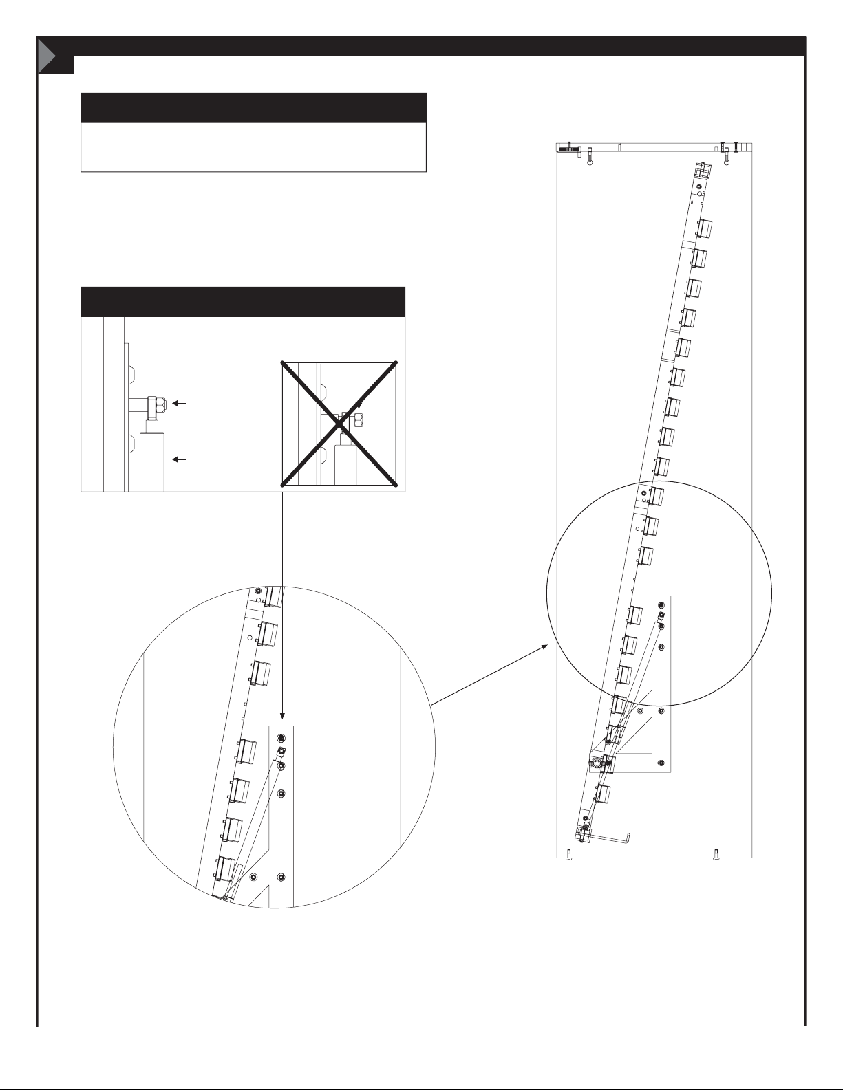
DISASSEMBLY
7
Let the bed frame sink back into the cabinet and remove the cylinders.
UNSCREW THE CYLINDERS OF THE L BRACKETS.
40
Page 41

DISASSEMBLY
8
Unscrew and remove the bearing supports.
KI-985-P
FRONT VIEW
Image 1
9
Now you can unscrew the bed from the wall and continue the disassembly.
KI-985-P
41
Page 42

YOU
andUS
LONG
TIME
for
 Loading...