

Sandia 12-Gallon, 1200 PSI Hard Surface Extractor User Manual

1200 PSI Hard Surface Extractor
By Sandia Products
Safety, Operation and Maintenance
Manual with Parts List
Please read before use!
Please ll out the following information:
Model No:
Serial No:
Distributor Name:
Distributor Phone No:
Date of Purchase:
1200 Psi
REGISTER
YOUR
MACHINE
ONLINE!
1200 psi Hard Surface Extractor
Model No. 80-5000
15571 Container Lane, Huntington Beach, CA 92649
Phone: 714-901-8400 | Toll Free: 800-983-5834 | Fax: 714-901-8404
info@sandiaplastics.com | www.sandiaplastics.com
© 2012 Copy Rights Reserved Sandia Products, Inc.
Important Information and Safety Instructions
Register your Machine at www.sandiaplastics.com/registration.aspx
Serial No:
© 2012 Copy Rights Reserved Sandia Products, Inc.
Reliable Power
Exceptional Vacuum
Safe & Easy to Use
Versatile
Easy Transport
Patented Features

Dear Valued Customer,
Congratulations on the purchase of your 12-Gallon, 1200 PSI Hard Surface Extractor!
The world of carpet cleaning is becoming more high-tech and competitive and we strive
to provide you with the most innovative products. Our Hard Surface Extractor is yet
another example of this, bringing a new dimension to tile, grout and carpet extracting
with its cutting-edge features, quality and value.
Please review this manual, paying careful attention to the Safety Instructions section.
Keep in mind that any unnecessary damage, neglect or abuse of this machine will void
your warranty. You can be condent that simple maintenance will ensure that your Hard
Surface Extractor provides quality performance for many years to come.
If warranty questions arise, please consult this manual or contact your distributor. Should
you have any questions regarding maintenance, replacing parts or ordering parts, please
call an authorized distributor.
Before you begin using your Hard Surface Extractor, please thoroughly review the
Owner’s Manual.
Again, congratulations on the purchase of your 12-Gallon, 1200 PSI Hard Surface
Extractor!
(2) 1200 PSI Hard Surface Extractor 1200 PSI Hard Surface Extractor (39)

Notes:
Operating Manual Table of Contents
Warranty Policy ............................................................................................................4
RMA Procedure .............................................................................................................5
1.0 Safety Instructions .................................................................................................5
2.0 Grounding Instructions .........................................................................................6
3.0 Prepare Unit for Use ..............................................................................................7
3.1 Automatic Chemical Feed ................................................................................7
3.2 Pressure Pump System ......................................................................................9
3.3 Vacuum System ................................................................................................. 9
4.0 Set-Up and Operating ..........................................................................................10
4.1 Water and Chemical Dilution - Auto Fill .......................................................10
4.2 Connection of Solution Hose ..........................................................................12
4.3 Power Priming the High Pressure Pump .........................................................13
4.4 Connection of Vacuum Hoses .........................................................................13
4.5 Connection of Auto-Dump Hose ....................................................................14
4.6 Adjusting the Pressure.....................................................................................15
4.7 Switch Panel ....................................................................................................17
5.0 Shutdown Procedures ..........................................................................................18
6.0 Maintenance .........................................................................................................19
6.1 Clean Chemical Feed Filter ...........................................................................19
6.2 Clean Chemical Feed Foot Valve ....................................................................19
6.3 Clean Fresh Water Tank Filter ........................................................................19
6.4 Clean Vacuum Shut-Off Float Assembly Screen ............................................19
6.5 Clean Clear View In-Line Filter......................................................................20
6.6 Clean Auto-Dump Pump-Out ........................................................................21
6.7 Rinse Out Recovery Tank ............................................................................... 21
6.8 Clean Auto-Dump Pump-Out .........................................................................21
6.9 Flush Solution Tank Pump .............................................................................. 22
6.10 Clean Pump Inlet Filter .................................................................................23
6.11 Flush Chemical System .................................................................................24
6.12 WD-40 Vacuum Motors ................................................................................ 25
7.0 Storage and Freeze Protection ............................................................................25
8.0 Trouble Shooting Guide ....................................................................................... 27
9.0 Wiring Diagram ...................................................................................................29
10.0 Solution Tank Schematic Drawing and Parts List .......................................... 30
11.0 Recovery Tank Schematic Drawing and Parts List ........................................32
12.0 Base with Vac Components Schematic Drawing and Parts List.................... 34
13.0 Base with Vac and Pump Components Drawing and Parts List ................... 36
(38) 1200 PSI Hard Surface Extractor 1200 PSI Hard Surface Extractor (3)

New Equipment Warranty
Lifetime warranty on molded body parts, 1-year on vacuum motors, pumps, tools and all
electrical components.
Warranty Policy
All equipment is inspected and tested before shipping from the manufacturer. All parts are
warranted to be new and free from defects in workmanship and material, under normal use to the
original retail purchaser. This warranty limits manufacturer’s liability for defects in workmanship
or materials for replacement of defective parts only. The manufacturer accepts no liability for
incidental or consequential damages arisen from the use of any equipment, defective or not. This
warranty is in lieu of all expressed or implied warranties and is extended only to the original retail
purchaser. Manufacturer sales and service representatives are not authorized to waive or alter the
terms of this warranty, or to increase the obligations of the manufacturer under the warranty. Parts
replaced or repaired under this warrant are warranted for the remainder of the original warranty
period.
Freight charges and travel charges to and from the service provider shall be covered for ninety (90)
days from the purchase date. After the ninety (90) day period, these freight charges shall be paid
by the equipment owner, subject to manufacturer discretion. Certain circumstances may require
additional consideration. No travel charges shall be covered after ninety (90) days.
The manufacturer covers up to one (1) year (365 days) of service labor at the manufacturer’s
calculated hourly labor rate/repair time when performed by a manufacturer’s authorized service
provider. Ultimately, labor reimbursement costs are at the discretion of the manufacturer. After
one (1) year, the original retail purchaser is responsible for all labor costs with no manufacturer
reimbursement.
The original purchaser must contact the manufacturer to follow correct RMA/warranty procedures.
They must have a copy of the RMA Sheet enclosed in the box with the returned item. No returns
shall be authorized unless the proper RMA procedures are followed. It is the responsibility of the
distributor to repair the customer’s equipment as soon as possible. If the distributor does not have
the facilities to repair the equipment, it may be shipped or taken to an authorized service center for
repair.
The manufacturer charges a 15% restocking fee for any items that are being returned to stock. Items
must be new, unused, free of damage and are only good for up to one (1) year. After one (1) year,
the manufacturer does not accept the return of any item(s) for a reimbursed price.
Authorized warranty replacement parts need to come directly from the manufacturer. Any use of
any other parts will void warranty. Sandia Products does not reimburse for parts used by customer
that were not supplied directly for the machine under warranty.
The customer must contact the manufacturer prior to working on or changing out of any parts, etc.
The manufacturer must issue an RMA Sheet containing approved labor time and replacement parts.
Do not send parts or equipment back to the manufacturer without an RMA Number and approval.
No labor will be paid for, nor parts cost paid for or reimbursed, that have not previously been
approved by the manufacturer. All warranty work must be approved and authorized to qualify, and
appropriate warranty procedures must be followed.
The warranty starts on the purchase date by the original purchaser from an authorized Sandia
Products distributor, subject to proof of purchase. The Machine Registration Form must be
completed online at the time of purchase. If proof of purchase cannot be identied, the warranty
start date is ninety (90) days after the date of sale to an authorized Sandia Products distributor.
13.0 Base with Vacuum and Pump Components
Parts List
Drawing No. Item No. Item Description Quantity
A 10-0832 S/R Strap Bolts 1
B 10-0834 Pump Flat Washer 16
C 10-0831 S/R Bracket for Extractor 1
D 80-0059-4 1200 psi Extractor Gauge 1
E 80-0112-UN 1200 psi Unloader Valve/Regulator 1
F 10-0838 Pigtail for Extractor (Pigtail Cord only) 2
G 10-0850 Strain Relief for Extractor Pigtail 2
H 10-0851 Strain Relief Nut for Extractor 2
I 10-0379 8-32 x 3/8 Screw 2
J 10-0400-D Keeper for Extractor Latch 1
K N/A Plastic Insert 1
L 10-0834 Flat Washer 4
M 10-0835-N Nut for Pump Bolt on Extractor 4
N 10-0835-B Pump Bolt 100 psi Extractor 4
O 80-0112 1200 psi Pump Kit 1
Q 10-0826 3/4” Hose Clamp for Extractor 2
S N/A Part of Pump
T N/A Part of Pump
U 10-0822 Exhaust Grate for Extractor 1
X N/A Part of Pump
(4) 1200 PSI Hard Surface Extractor 1200 PSI Hard Surface Extractor (37)
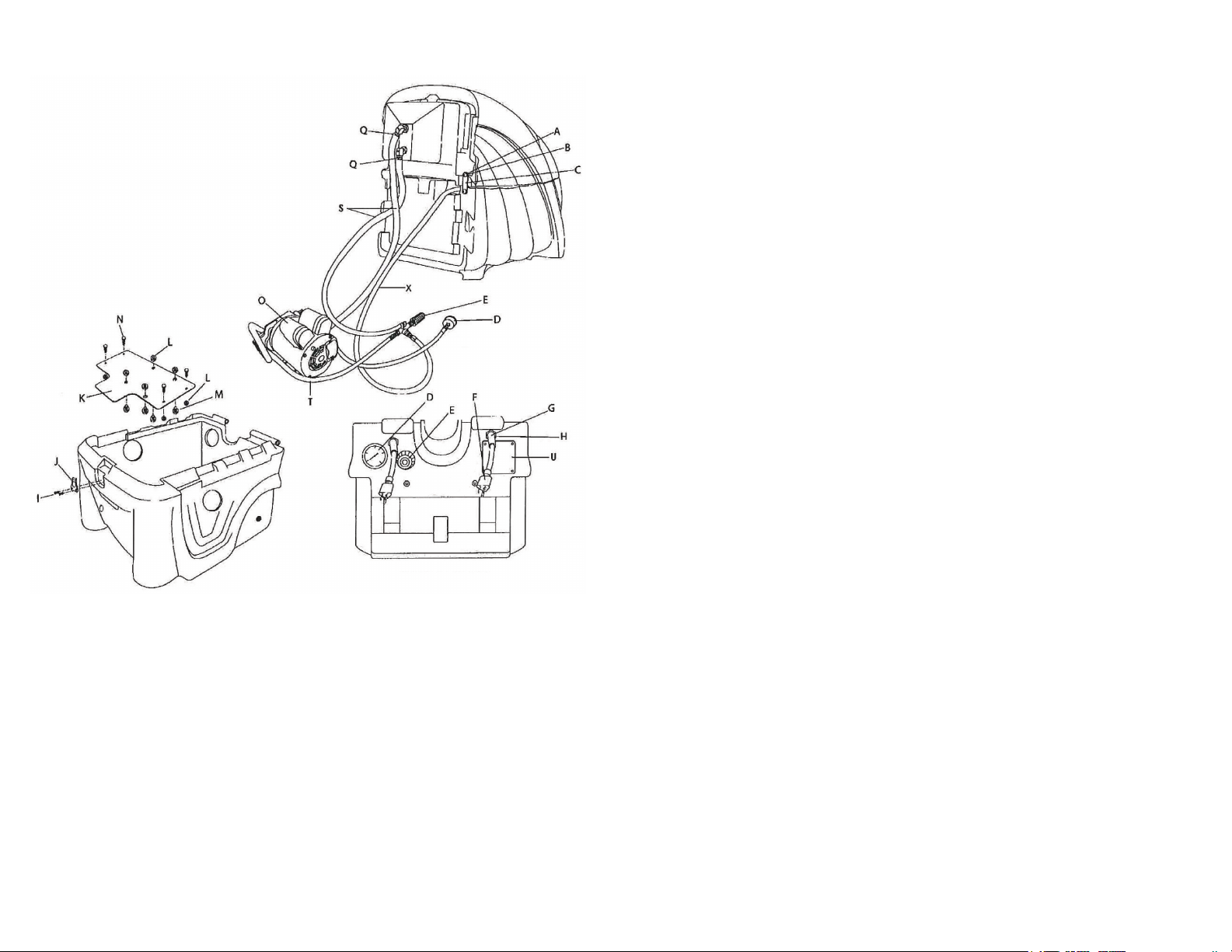
13.0 Base with Vacuum and Pump Components
Schematic Drawing
Returned Material Authorization (RMA) Procedure
Original purchaser must contact the manufacturer to follow correct RMA/warranty
procedures and must include a copy of RMA Sheet enclosed in the box with the returned
item. No returns shall be authorized unless the proper RMA procedures are followed.
It is the responsibility of the distributor to repair the customer’s equipment as soon as
possible. If the distributor does not have the facilities to repair the equipment, it may be
shipped or taken to an authorized service center for repair.
Customer must contact the manufacturer prior to working on or changing out any
parts, etc. Manufacturer must issue an RMA Sheet containing approved labor time and
replacement parts. Do not send parts or equipment back to manufacturer without an RMA
Number and approval. No labor will be paid for, nor part costs paid for or reimbursed that
have not been previously approved by manufacturer. All warranty work must be approved
and authorized to qualify and appropriate warranty procedures must be followed.
1.0 Safety Instructions
READ THIS MANUAL BEFORE USING YOUR HARD SURFACE EXTRACTOR.
KNOW THE PROPER OPERATION, CORRECT APPLICATIONS AND THE
LIMITATIONS OF THIS EQUIPMENT BEFORE USE.
Reduce the Risk of Fire, Electric Shock or Injury:
• Use only as described in this manual. Use only the attachments recommended by the
manufacturer.
• Test all outlets with an outlet tester before plugging machine into any outlet. Plug cord
into the nearest grounded outlet.
• Overloaded circuit may not always trip circuit breaker. Reduced voltage to machine
on overloaded circuit will prevent components from operating properly.
• The two (2) power cords must be plugged into separate circuits during operation.
Power Cord 1 (left side) must be on a 20 Amp circuit to use both vacuums. Power
Cord 2 (right side) must be on a 15 Amp circuit if the Auto Pump-Out is not used or a
20 Amp circuit if it is used.
• DO NOT unplug by pulling on the cord, grasp the plug. DO NOT pull unit by the
cord.
• Keep cord away from heated surfaces.
• DO NOT use if cord or plug are damaged.
• Never attempt adjustments or repairs while the machine is plugged in.
• DO NOT use outdoors, in standing water on wet surfaces.
• Pay close attention when using machine near children.
• DO NOT pick up ammable or combustible materials or use machine where they may
be present.
• DO NOT clean with solutions that are at temperatures above 140 degrees Fahrenheit.
• DO NOT allow pump to run dry. Always maintain an adequate solution level to supply
solution pump.
(36) 1200 PSI Hard Surface Extractor
1200 PSI Hard Surface Extractor (5)

1.0 Safety Instructions Continued
• DO NOT leave machine outdoors, in extreme heat or cold. Harsh weather elements
will damage components and void warranty.
• Lift using only the appropriate handles.
• Always wear the appropriate clothing and safety equipment when operating the
machine.
• Keep all body parts, hair and loose clothing away from openings and moving parts.
• Use extra care when cleaning stairs. DO NOT move unit up or down stairs when tanks
are full of water. Drain solution and recovery tanks before moving unit up or down
stairs.
• Water may spill, drip or be exhausted from vacuums during operation. Place unit in an
area where water will not cause damage or use a drop cloth to protect surfaces.
• DO NOT use Citrus Acid, Buterol or harsh degreasers inside the machine.
• Use common sense to protect yourself and others from injury when using the machine.
2.0 Grounding Instructions
DANGER: IMPROPER GROUNDING METHOD CAN RESULT IN A RISK OF
ELECTRIC SHOCK.
Electrical equipment must be grounded. If the machine should malfunction or breakdown,
grounding provides a path of least resistance for electrical current to reduce the risk of
electric shock. The machine is equipped with a cord containing a grounding conductor
and grounding plug. The plug must be inserted into an appropriate outlet that is properly
installed and grounded in accordance with all local codes and ordinances.
If repair or replacement of the cord or plug is necessary, DO NOT connect the grounded
wire to a at bed terminal. The grounding wire is the wire with insulation and an outer
green surface, with or without yellow stripes.
12.0 Base with Vacuum Components
Parts List
Drawing No. Item No. Item Description Quantity
A 10-0848-B 1-1/2” 90 Degree ABS Street Elbow 3
B SN-12-MFLD Extractor Motor Manifold 2
C 80-0003-A 1-1/2” Black Lined Gray Hose 2
D 10-0419-A Screw for Extractor Hatch 12
E 10-0822 Exhaust Grate for Extractor 3
F 10-0836 19” Axle for Extractor 1
G 10-0807 Wheels for Extractor 2
H 10-0820 End Cap for Rod on Extractor 4
I 10-0808 Caster for Extractor 2
J 10-0816 Caster Bolt 1/4-20 x 1/2 Hex Bolt 8
K 10-0816 Part of Caster Bolt
L 10-0155 Hose Cuff Straight 1
N T-A001 Cooling Duct 2
O 10-0811 2-Stage Extractor Motor 1
P 10-0833-L Manifold Bolt 10-32 x
1/4” Hex Socket Head Cap Screw 6
Q 10-0204 Motor Mount Back-Up Washer 6
R 80-0116 Spacer for 3-Stage Extractor Motor 6
S 10-0810 3-Stage Extractor Motor 1
T 10-1030-S3 3-Stage Extractor Motor Gasket 1
U 10-1030-S2 2-Stage Extractor Motor Gasket 1
Grounding Method
The Hard Surface Extractor is designed to run on a 20 Amp circuit (use Cord 1, the righthand cord, found by standing behind the machine). 20 Amp circuits are normally found in
kitchens and bathrooms. If a circuit breaker trips during operation, reset the breaker and
move the electrical cord to a different outlet to resume operation.
The equipment is for use on a normal 120 Volt circuit. It includes a grounded plug
(shown in Figure A). A temporary adapter (Figure B and C) may be used to connect this
plug into a 2-pole receptacle (Figure B) if a properly grounded outlet is not available.
The temporary adapter should be used only until a properly grounded outlet
(Figure A) can be installed by a qualied electrician. The green colored rigid ear lug or
the like extending from the adapter must be connected to a permanent ground, such as a
properly grounded outlet box cover. Whenever an adapter is used, it must be held in place
by a metal screw.
WARNING:
Improper connection of the equipment grounding conductor can result in a risk of electric
shock. Check with a qualied electrician or service person if you are in doubt as to
whether the outlet is properly grounded. DO NOT modify the plug provided with
(6) 1200 PSI Hard Surface Extractor 1200 PSI Hard Surface Extractor (35)
 Loading...