

Page 1
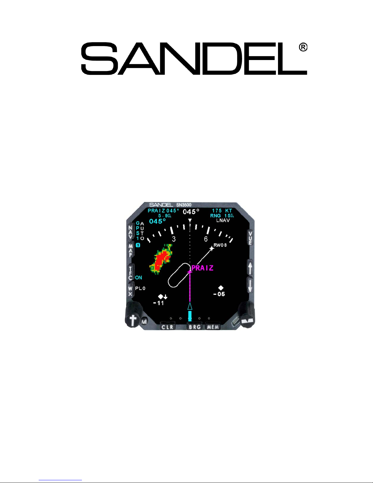
SN3500
Primary Navigation Display
with
Reversionary At titude M ode
And
LNAV Roll Steering
Installation Manual
Sandel Avionics, Inc.
2401 Dogwood Way
Vista, CA 92081
Phone (760) 727- 4900
FAX (760) 727- 4899
Website: www.sandel.com
Email: [email protected]
82005-IM-R
Page 2

[This page intentionally left blank]
82005-IM-R Sandel SN3500 Installation Manual Page ii
Page 3

Table of Contents
1 General Information ....................................................................................................... 1-1
1.1 Introduction .................................................................................................................................................. 1-1
1.1.1 EXPORT CONTROL NOTICE ............................................................................................................. 1-1
1.2 Equipment Description ............................................................................................................................... 1-1
1.2.1 Features ................................................................................................................................................. 1-1
1.3 Installation Planning ................................................................................................................................... 1-2
1.3.1 Installation Planning Cycle .................................................................................................................... 1-2
1.3.2 Post Installation Summary ..................................................................................................................... 1-3
1.4 Interface Planning ........................................................................................................................................ 1-3
1.4.1 Compass System................................................................................................................................... 1-3
1.4.2 Autopilot Switching ................................................................................................................................. 1-4
1.4.3 Autopilot Course and Heading Datum .................................................................................................. 1-5
1.4.4 GPS Annunciators ................................................................................................................................. 1-5
1.4.5 VLOC Navigation – Internal NAV Converter ........................................................................................ 1-5
1.4.6 VLOC Navigation – External NAV Converter ....................................................................................... 1-5
1.4.7 Marker Beacon ....................................................................................................................................... 1-6
1.4.8 Bearing Pointers (VOR, ADF, and TACAN) ......................................................................................... 1-6
1.4.9 ARINC Channels ................................................................................................................................... 1-7
1.4.10 DME Interface ........................................................................................................................................ 1-7
1.4.11 Special Considerations for GARMIN GNS430/530/GTN6XX/7XX ..................................................... 1-7
1.4.12 Special Considerations for UPS GXXX ................................................................................................ 1-9
1.4.13 Brightness Control ................................................................................................................................. 1-9
1.4.14 Traffic Option .......................................................................................................................................... 1-9
1.4.15 Data Link Weather Option ..................................................................................................................... 1-9
1.4.16 TACAN Option .....................................................................................................................................1-10
1.4.17 Night Vision Support Option ................................................................................................................1-10
1.4.18 Reversionary Attitude Option ..............................................................................................................1-10
1.4.19 Roll Steering Option .............................................................................................................................1-10
1.5 Disclaimer ...................................................................................................................................................1-10
2 Technical Information ................................................................................................... 2-1
2.1 General .......................................................................................................................................................... 2-1
2.2 Part Numbers ............................................................................................................................................... 2-1
2.2.1 Installation Kit and Accessories ............................................................................................................ 2-2
2.2.2 Bill of Materials – SN3500 Install Kit ..................................................................................................... 2-2
2.3 Approval Summary ..................................................................................................................................... 2-2
2.3.1 License Requirements ........................................................................................................................... 2-2
2.3.2 Approval Data ........................................................................................................................................ 2-2
2.3.3 Technical Standard Order Stipulation ................................................................................................... 2-3
2.3.4 Installation and Operational Approval Procedures............................................................................... 2-3
2.4 Physical, and Electrical Properties ........................................................................................................... 2-5
2.4.1 Physical Dimensions.............................................................................................................................. 2-5
2.4.2 Summary Operational Characteristics .................................................................................................. 2-5
82005-IM-R Sandel SN3500 Installation Manual Page iii
Page 4

2.5 Connector Summary ................................................................................................................................... 2-5
2.5.1 Connector P1 ......................................................................................................................................... 2-6
2.5.2 Connector P2 ......................................................................................................................................... 2-9
2.5.3 Connector P3 .......................................................................................................................................2-12
2.5.4 Signal Characteristics Table ................................................................................................................2-13
2.6 ARINC 429 ...................................................................................................................................................2-15
2.6.1 ARINC 419/429 Serial Data Receivers Interfaces .............................................................................2-15
2.6.2 ARINC 419/429 Serial Transmitter Interfaces ....................................................................................2-17
3 Installation ...................................................................................................................... 3-1
3.1 General .......................................................................................................................................................... 3-1
3.1.1 Unpacking and Inspecting Equipment .................................................................................................. 3-1
3.2 Installation Consider ations ........................................................................................................................ 3-1
3.2.1 General Considerations ......................................................................................................................... 3-1
3.2.2 Cooling Considerations ......................................................................................................................... 3-1
3.2.3 Mechanical Installation Considerations ................................................................................................ 3-1
3.2.4 Electrical Installation Considerations .................................................................................................... 3-2
3.3 Signal Details ................................................................................................................................................ 3-4
3.3.1 Connector P-1 Pinout Description......................................................................................................... 3-4
3.3.2 Connector P-2 Pinout Descriptions ....................................................................................................... 3-7
3.3.3 Connector P-3 Pinout Descriptions .....................................................................................................3-10
4 Setup Procedu res .......................................................................................................... 4-1
4.1 General .......................................................................................................................................................... 4-1
4.2 Accessing the Maintenance Menus .......................................................................................................... 4-1
4.3 Equipment/Configuration S elections ....................................................................................................... 4-1
5 Operating Details ........................................................................................................... 5-1
6 Instructions For Continued Airworthiness ................................................................. 6-1
6.1 General .......................................................................................................................................................... 6-1
7 Appendix A: Post-Inst allatio n Pro cedur es ................................................................ 7-1
7.1.1 Page 1: INDEX ...................................................................................................................................... 7-2
7.1.2 Page 2: SYSTEM.................................................................................................................................. 7-3
7.1.3 Page 3: COMPASS SYSTEM ............................................................................................................. 7-4
7.1.4 Page 4: ADF/TACAN/ MKR ................................................................................................................. 7-7
7.1.5 Page 5: NAV/ILS/DME 1 ...................................................................................................................... 7-9
7.1.6 Page 6: NAV/ILS/DME 2 ....................................................................................................................7-12
7.1.7 Page 7: GPS1 .....................................................................................................................................7-14
7.1.8 Page 8: GPS2 .....................................................................................................................................7-16
7.1.9 Page 9: FCS EMULATION ................................................................................................................7-18
7.1.10 Page 10: OBS / RELAY / CDI ............................................................................................................7-20
7.1.11 Page 11: WX-500 ...............................................................................................................................7-22
7.1.12 Page 12: Traffic ...................................................................................................................................7-23
7.1.13 Page 13: STATUS ..............................................................................................................................7-24
82005-IM-R Sandel SN3500 Installation Manual Page iv
Page 5

7.1.14 Page 14: BRT/DATA BLK ..................................................................................................................7-25
7.1.15 Page 15: Power ..................................................................................................................................7-27
7.1.16 Page 16: Software CRC .....................................................................................................................7-28
8 Appendix B: Environmental Qualification Form ....................................................... 8-1
9 Appendix C: Sample FAA Form 337 ........................................................................... 9-1
10 Appendix D: Sample Airplane Flight Manual Supplement .................................... 10-1
11 Appendix E: Checkout Procedures .......................................................................... 11-1
11.1 Functional Ground Test Proc edures /Repor t .........................................................................................11-1
11.1.1 Introduction ...........................................................................................................................................11-3
11.1.2 Test Procedures and Results ..............................................................................................................11-3
11.1.3 Physical Installation .............................................................................................................................11-3
11.1.4 Wiring Verification and Initial Power-Up .............................................................................................11-3
11.1.5 System Configuration ..........................................................................................................................11-4
11.1.6 System Functions ................................................................................................................................11-4
11.1.7 Compass System Interface .................................................................................................................11-4
11.1.8 NAV Source Selection .........................................................................................................................11-5
11.1.9 LOC/GS Deviation ...............................................................................................................................11-6
11.1.10 BRG Source Selection .....................................................................................................................11-6
11.1.11 DME Selection .................................................................................................................................11-6
11.1.12 GPS Interface and Control ..............................................................................................................11-7
11.1.13 Marker Beacon Interface .................................................................................................................11-8
11.1.14 Flight Control System Interface .......................................................................................................11-9
11.1.15 Stormscope ® Interface ...................................................................................................................11-9
11.1.16 Traffic ................................................................................................................................................11-9
11.1.17 NVIS Control ................................................................................................................................. 11-10
11.1.18 Reversionary Display Control ....................................................................................................... 11-10
11.1.19 Additional Testing.......................................................................................................................... 11-10
11.2 EMI/RFI Test Procedures ....................................................................................................................... 11-10
11.2.1 Nav/Com Testing .............................................................................................................................. 11-10
11.2.2 General Testing ................................................................................................................................ 11-11
11.2.3 Additional Testing ............................................................................................................................. 11-12
11.3 Operational Flight Test P rocedur es/Repor t ....................................................................................... 11-13
11.4 Introduction ............................................................................................................................................. 11-15
11.5 Test Procedures ...................................................................................................................................... 11-15
11.5.1 Pre-Departure Operations ................................................................................................................ 11-15
11.5.2 Enroute Operations ........................................................................................................................... 11-16
11.5.3 GPS Approach Operations............................................................................................................... 11-17
11.5.4 TACAN Approach Operations .......................................................................................................... 11-17
11.5.5 ILS Approach Operations ................................................................................................................. 11-17
11.5.6 Additional Testing ............................................................................................................................. 11-18
12 Appendix F: Li st of Ef f ectiv e D rawing s and A ttach ments .................................... 12-1
82005-IM-R Sandel SN3500 Installation Manual Page v
Page 6

Revision History
Revision Date Comments
Updated for AR1617
R 01/27/2015
P 10/30/2013
N 08/21/2013
M 03/02/2012
L 11/09/2011
K 11/30/2010
Section 1.1.1: Updated ITAR Note
Section 1.2.1: Updated ITAR note for TACAN display o ption.
Section 7.1.3.1: Added PTCH CAL field to table.
Updated for AR 1378
Section 1.4.4: GTN series added.
Section 1.4.6: GTN6XX/7XX added. Series re sistor note remov ed from
second paragraph.
Section 1.4.11: Table added for GTN6XX/7XX.
Section 2.2.2: Removed USB cable from Inst allation Kit BOM
Section 2.5.1 Connector P-1 description: Removed th e word “series” fro m Pins
6 and 37. Removed Superflag note.
Section 3.3.1: P1-6, P1-36, P1-37, and P1-23: remov ed the word “se ries”.
Section 7.1.3.1: Typo corrected “HSI”
Section 12: Updated Effective Drawing list due t o revision of 82006-10 sheet
27 to show new equipment selection for GTN6XX/7XX.
Section 12: Update to DWG 82005-10 sheet 28 to show new equipment
selection for GTN6XX/GTN7XX.
Section 42: Sheet 42 Added for NAV/GS Superflags.
Updated for AR 1357 Section 3.3.1:
Corrected ARINC 429 designations for P1-39 from 429B to 429A and P1-25
from 429A to 429B.
Corrected Environmental Test Credit Analysis docum ent number in
Environmental Qual Form for LED Models from 82009-01 44 to 82005-0091.
Section 7.1.15: Maintenance page screenshot u pdated to reflect ne w internal
power supply voltage requirements.
Section 12: Updated Effective Drawing list due t o revision of 82005-10 sheet
19.
Section 12: Correction to DWG 82005-10 sheet 19 – Pi n number P1-7 was
incorrectly shown as P1-22 and pin number P1-2 2 was incorre ctly shown as
P1-7.
Updated for software version 4.05 AR1221
Section 1.4.13: Added external brightness co ntrol.
Section 7.1.10: Added LED backlight requi rement for Rol l Steering.
Updated for software version 4.04 AR1207
Section 1.3.1: Correction to positioner and extraction to ol part number s.
Section 1.4.19: New Roll Steering
Section 2.2: SN3500 part numbers added.
Section 2.6.1: Added label 121 to table.
Section 7.1.2: Added Loc/GS pointer selection option.
Section 7.1.10: Added instructions for roll steering key entry.
Section 10.0: Added Sample AFMS LNAV/Roll Steering text.
Updated for software version 4.03 AR1154
Section 1.1.1: Added TACAN ITAR Export Notice. Removed NVIS notice.
Section 1.3.1: Added list of recommended crimp tool s.
Section 2.2.2: Positronics P/Ns added for co nnectors
Section 2.6.1: Updated 429 Label Description table.
Section 2.6.2: Table formatting updated.
Section 7.1.14: Changes to maintenance pag e 14: added procedu re for
calibrating the minimum brightness when an external brightness control is
used.
82005-IM-R Sandel SN3500 Installation Manual Page vi
Page 7

Revision
Date
Comments
J 05/27/10
Updated for software version 4.02 AR1110.
Section 12: DWG 82005-10 sheet 41
I
N/A
Intentionally skipped.
Updated for software version 4.01 AR1087.
Section 7.1.1 corrected reference from ST3400 to SN3500.
Updated for software version 4.00 AR1055.
Section 12: Added 82005-41 to drawing list.
Updated for software version 3.05, AR1032.
Page 12-2: Added 82005-10 pp 40, updated revisions.
Corrected TOC
Section 3.3.2: Updated P2-3/35 pin description and added note for composite
LOC DEV calibration procedure.
Section 7.1.2: New TACAN Relay out pin configuration.
Section 7.1.3: New Reversionary Attitude Enable pin configuration.
Section 7.1.5: Added composite LOC DEV calibration procedure. Added
reference to cal procedure and added GAIN selection to table. Updated figure.
Section 7.1.6: Added reference to cal procedure and added GAIN selection to
table. Updated figure.
Section 7.1.14: New Dimmer Control configuration.
Section 11.1.9: Added LOC/GS deviation test. Following sections
renumbered.
H 8/24/09
G 3/2/09
F 8/26/08
Section 3.3.1 change inverter range from 360 - 440Hz. to 240 - 560 Hz.
Section 3.3.2 change inverter range from 360 - 440Hz. to 240 - 560 Hz.
Page vi: Updated revision history.
Section 1.2.1: Added Optional Reversionary Display.
Section 1.4.17: Added NVIS paragraph
Section 1.4.18: New Reversionary Display paragraph.
Section 2.3.2: added TSO-C3d, and –C4c.
Section 2.5.3: Added REV CNTRL Label to connector pin 6.
Section 2.6.1: Added ARINC labels for Roll, Pitch, and Lateral Acceleration.
Section 3.3.3: Added Reversionary Control signal to connector P3 pin 6.
Section 7.1.3: Updated compass maintenance page for Reversionary Attitude.
Section 7.1.4: Added TACAN 1 & 2 Multi-Channel selection.
Section 7.1.5: Added DME1 Multi-Channel selection.
Section 7.1.6: Added DME2 Multi-Channel selection.
Section 11.1.17: Added ground test procedure.
Page 2-12: Assigned P3-13 to NVIS Control
Page 3-12: Added NVIS P3-13 description
Page 7-20: Modified Maint. Page 14. (NVIS control monitor)
Page 11-10: Added NVIS ground test step
82005-IM-R Sandel SN3500 Installation Manual Page vii
Page 8

Revision
Date
Comments
E 6/16/08
Updated for software version 3.04 and TACAN support
Page 11-16: TACAN approach operations added.
A/R 958
Added 82005-10 sheet 38
A/R 924
Page 8-2: RTCA/DO-160E Environmental Qualification Form added.
A/R 824 Updated following pages: Page iv, revision; Page 2-4, weight in kg;
updates. Pages 1, 33 & 36 of installation drawings updated.
A/R 806 & A/R 820 Updated for software version 2.01, version 3.00, and minor
corrections. Sample AFMS updated including FIS-B weather.
B
N/A
Skipped
A3
06/06/2005
A/R 782 Minor doc changes for production release
A2
05/06/2005
A/R 782 Minor doc changes and pin-out corrections
Page 1-1: Added export control notice.
Page 1-2: TACAN added.
Page 1-6: TACAN added to bearing pointer inputs.
Page 1-8: NVIS Display Brightness / [M] button LED operation note added.
Page 1-8: TACAN added
Page 2-1: Low voltage operation support note added
Page 2-1: Update part number definition
Page 2-2: USB cable added to Bill of Materials
Page 2-5: Low voltage operation note added
Page 2-6: TACAN added
Page 2-9: TACAN added
Page 2-15: TACAN label added
Page 3-4: TACAN added to pinout description
Page 3-7: TACAN added to pinout description
Page 7-1: Index page updated for TACAN capability
Page 7-20: Page updated for NVIS brightness/ M button LED status
Page 11-5: TACAN added to NAV source selection
Page 11-6: TACAN added to bearing source selection
Page 11-15: TACAN added to enroute operations checks
D1 01/31/08
D 11/15/07
C1 12/16/05
Updated Effective drawing list.
Modified 82005-10 sheet 28.
Page 1-1: Updated applicable TSOs and ETSO.
Page 2-1: Lamp kit added.
Page 2-2: Updated applicable TSOs and ETSO
Pages 3-9 & 3-10: Clarify pin description P2-28, P2-13.
Clarify composite input connection with analog NAVs.
Page 3-9: Clarify P2-10 HDG/CRS Excitation connection when not connected.
Page 5-1: Added reference to 82005-PG (SN3500 Pilot’s Guide) for light
source identification and data color coding details.
Page 7-1: Updated INDEX maintenance page image.
Page 7-10: Updated GPS-1 maintenance page image.
Pages 7-10 & 7-12: Added selections for ARINC 429 on GPS 1 and GPS 2
maintenance pages.
Page 7-11: Updated GPS-2 maintenance page image.
Pages 7-11 & 7-12: Added selections for GPS Approach Mode Active Status
on GPS1 and GPS2 maintenance pages.
Page 7-15: Added definition for lateral and vertical deviation output calibration
in maintenance pages.
Page 7-18: KTA-810 configuration note added.
Page 7-19: Updated BRT/DATA BLK maintenance page image.
Pages 2-6 and 3-5, deviation left/right; Pages 3-9 and 7-13, FCS selection;
Page 3-12, P3-10 NAV menu typo; Pages 12-1 and 12-2, drawing rev
C 11/17/2005
82005-IM-R Sandel SN3500 Installation Manual Page viii
Page 9

Revision
Date
Comments
A1
04/21/2005
A/R 780 minor doc and dwg changes
A
03/31/2005
Initial release
82005-IM-R Sandel SN3500 Installation Manual Page ix
Page 10

1 General Information
1.1 Introduction
The information contained within this Installation Manual describes the features,
functions, technical characteristics, components, approval procedures, installation
considerations, setup procedures, checkout procedures, and instructions for
continued airw or thiness for the S andel Av i onics SN35 00 Primary Navigation Display.
The SN3500 is the industry’s most capable electronic HSI. It can be used to directly
replace a mechanical DG or HSI as a primary displ ay , or t he SN3500 can be used as
a replacement or upgrade for an existing Sandel SN3308 navigation display. It is
signal (but not plug) compatible with the SN3308, and is an upgrade in performance
with both an i mprov ed d is play and a dded fe atur es.
1.1.1 EXPORT CONTROL NOTICE
Prior to 20 January, 2015 - The TACAN display option software key (p/n 90143-TCN)
is subject to the licensing jurisdiction of the Department of State in accordance with
the International Traffic in Arms Regulations (ITAR) (22 CFR 120 – 130). It may not
be exported (sent, transferred, disclosed or otherwise released to a foreign person)
without a license issued by DDTC.
General Information
1.2 Equipment Descr iption
1.2.1 Features
The Sandel SN3500 Primary Navigation Display is an advanced microprocessor
controlled airborne multipurpose electronic display which is FAA approved under
technical standard order TSO C6d, C34e, C35d, C36e, C40c, C41d, C113, C118,
and C119b. The SN3500 is also EASA approved under ETSO C113. T he SN3500
employs a patented active matrix liquid crystal (AMLCD) projection display. It is
designed to c ombin e th e functi ons of:
• Basic Horizontal Situation Indicator (HSI)
• Long-Range Navigation (GPS or FMS) Map Displ ay
• WX-500 Stormscope ® Display
• DME Readout
• Marker Beacon Indicator
• NAV Converter
• Autopilot Switching
• GPS Annunciators and External Mode S witches
• Optional Traffic Display
• Optional FIS-B Da ta Link weather display (software v ersion 3.00 and later)
• Optional Clas s B Night Vision (NV IS ) Co m pat ib l e (S o ft wa re 3 .04 a nd later)
• Optional Reversionary Attitude Display (Software 4.00 and later)
• Optional TACAN Display (Prior to 20 Janu ary , 2015 - ITAR Export Controlled)
• Optional Roll Steering Command output to A utopilot (Soft ware 4.04 and later)
82005-IM-R Sandel SN3500 Installation Manual Page 1-1
Page 11

Outputs of heading and course datum and bootstrap heading output are provided, as
well as L/R and U/D deviation output and flags. The versatile digital and analog
interface properties of the unit provide for compatibility with most VHF navigation
receivers, ADF’s, TACAN’s, DME’s, GPS’s, remote gyr os and flux gat es.
The SN3500 is designed to display the flight plan data from a connected GPS
receiver. The moving ma p database for the SN3500 as well as the internal op er at ing
system software are field loadable through the use of a portable computer equipped
with a USB port and a U SB ca pabl e ver sio n of Mi cros oft Wind ows .
Although simple, retrofit replacement of most existing three-inch PNI’s or HSI’s is
possible without additional features, we strongly encourage complete installation of
the unit with all compatible peripheral equipment interconnected to maximize its
functional capa bil ity .
1.3 Installati on Planning
General Information
Sandel Avionics has taken many equipment interface possibilities into consideration
during the design of the SN3500 to ensure maximum interoperability with other
avionics. Contact the factory with any questions about interfacing to specific avionics
equipment not cov ered in t he i nstal l atio n draw i ngs.
To simplify installation and installation planning, signals are wired to the SN3500 pins
per the installation diagrams and software setups are used in a post-installation
procedure to assign protocols/gradients to each pin based on the equipment
connected. There are separate maintenance menu pages for each equipment
function and i n mos t ca ses the s electi ons are ma de by equip ment ma ke/model .
1.3.1 Install ation Plan ning Cycl e
1) Compile an equipme nt list for th e aircra ft.
2) Study the feature list below, and determine the desired functional
characteristic s for the in stallati on.
3) Study the installation drawings to determine a basic interconnect scheme
and check for c on flicts .
4) Develop the speci fic wiring diagra ms unique to t he aircra ft.
5) Assemble required tools. Recommended crimp tools are given in the
following table .
82005-IM-R Sandel SN3500 Installation Manual Page 1-2
Page 12

General Information
Recommended Crimp Tools
22-28 AWG
20-24 AWG
Tool
Positioner
Extraction Tool
Positioner
Extraction Tool
Military P/N
M22520/2-01
M22520/2-09
M81969/1-04
M22520/2-08
M81969/1-02
Positronic
9507
9502-3
M81969/1-04
9502-5
M81969/1-02
ITT Cannon
995-0001-584
995-0001-739
N/A
995-0001-604
980-2000-426
AMP
601966-1
601966-6
91067-1
601966-5
91067-2
Daniels
AFM8
K41
M81969/1-04
K13-1
M24308/1-02
Astro
615717
615725
M81969/1-02
615724
M81969/1-02
High Density
Manufacturer
Hand Crimping
1.3.2 Post Ins tallatio n Summary
1) Prior to power-up review correct wiring by using standard ohmmeter and
voltage checks. Insure the correct orientation and positioning of the three
SN3500 ‘D’ connectors. The connector numbers are printed on the back
of the SN3500 for r efer enc e.
2) Review special items such as connection of the NAV receiver resolver
wiring.
Insertion/
Standard Density
Insertion/
3) Apply power to the SN3500, bring up in maintenance mode and
sequentially access each SN3500 maintenance page to correctly select
the installed equip ment .
4) Perform Ground Test proced ures
5) Perform Flight Test proc edur es.
1.4 Interface Planning
1.4.1 Compass System
Determine whether the SN3500 is to be used internally slaved or unslaved.
Unslaved operation would be appropriate when the SN3500 is bootstrapped to an
already slaved compass system or is being slaved to a panel mounted DG with
bootstrap outpu t.
Plan for:
High Resolution Digital Output from a Mid-Continent 4305 series DG with
gyro valid output, flux gate 10 Vac Fluxgate Excitation and Internal 26Vac
Inverter (int ern al slav i ng)
82005-IM-R Sandel SN3500 Installation Manual Page 1-3
Page 13

General Information
Quadrature stepper motor drive input from a Bendix/King KG 102 series
DG with compass valid output and flux gate connected directly to SN3500
(internal slav ing ).
3-wire ARINC 407 synchro DG with or without gyro valid output and
fluxgate. (int ern al sl avi ng )
3-wire ARINC 407 synchro remote or panel mounted DG self-slaved with
or without gy r o val id out put. ( SN 3500 unsl av ed)
ARINC 429 Heading Input from AHRS. Sandel monitors for Label 320,
Magnetic Headi ng D ata and L ab el 270 Sy ste m Stat us ( SN 3500 unsl av ed)
Internal slav i ng r eq ui r es c on nec tion of the flux gate exci tati o n to the SN3500 flux gate
reference input P2-24. This i nput is us ed only t o demod ulat e the flux g ate sig nals.
DG’s with XYZ bootstrap outputs require the master 400Hz inverter to be connected
to the SN3500 400Hz reference input on P1-16. This input is used to lock all 400Hz
inputs on P1 and 40 0Hz out puts i n th e SN3 500. This in put pres ents no l oading to th e
source.
Follow the information on the installation drawings, and plan to set up the appropriate
compass selectio ns on the co mpass sy stem mai ntenance pag e.
Internal slaving does not require the use of an external slaving accessory. Compass
calibration is performed using the SN3500 Compass maintenance page. The
SN3500 will provide standby heading operation from the flux gate alone in the event
of directional g y ro (D G) fail ure.
The SN3500 has a 3-wire ARINC 407 synchro bootstrap compass output if required
which is capabl e o f driv i ng elec tr onic l oa ds.
1.4.2 Autopi lot Switchi ng
The SN3500 has low level deviation and flag outputs intended to drive an autopilot.
These outputs feed from the pilot selected navigation source. These outputs may
eliminate the need for an ex ter nal aut opilo t sw i tching rel ay.
However if an external switching relay is used (for instance for compatibility with an
existing installation) the SN3500 has protected Open Drain relay output discretes
intended to drive external switching relays. These outputs have 250ma maximum
current and pul l t o wi thi n 1 oh m o f gr ound.
NAV1 selection i s the default selection and no r elay driv er output di scr ete i s av ailabl e.
The NAV2, GPS-1, o r GPS-2 outputs can be used to operate a switching relay for
each source, allowing the pilot to control the NAV source selection from the front
panel of the SN3500. This is referred to as “master” mode and it is the preferred
mode of installation. In this configuration an additional remote switch/annunciator
panel for a GP S rec eiv er i s not req uire d.
In the event the aircraft has an existing GPS switch/annunciator panel or it is desired
that one be installed, the “GPS SELECTED-” input on the SN3500 is used to remote
82005-IM-R Sandel SN3500 Installation Manual Page 1-4
Page 14

sense the selection of the GPS1 and annunciate the selection. This is referred to as
“slave” mode. It al low s ann unci atio n of the s el ecti on on th e SN3 500 but does not use
the front panel NA V switch to select the GPS receiv er . This mo de i s o nl y av ai labl e fo r
use with a single GPS.
Master/Slave m ode s el ecti on i s do ne i n the N A V mai nten anc e pag e.
When any relay is used, the SN3500 uses a wraparound RELAY SENSE input,
which provides feed back of failure of the switching rel ay . A pole on th e ex t er nal r el ay
is used to ground an SN3500 input pin when the relay is in the energized position. If
the low signal is not detected, the SN3500 annunciates the relay failure by redlining
the NAV source display .
1.4.3 Autopi lot Course a nd Heading Datum
Course and heading dat um out puts are prov ide d. Thes e can be s elec ted to b e AC or
DC in the Flight Cont r ol System (FCS) maintenance page and depending on whether
Datum Excitation is co n nec t ed . The di r ec ti o n sense of these signals can be reversed
as required.
General Information
A Back-course discrete output is provided for annunciation or AFCS reverse-course
control when required. This operates during LOC operation when the aircraft is flying
with the tai l of the Cour se P oint er u p.
For older Century autopilots a Datum Excitation (5Khz) input is provided. However,
an external transfor mer coupl er must be fabrica ted. See installati on dra wing s.
1.4.4 GPS Annu nciators
For receivers without serial communication capability, discrete annunciator inputs are
provided for ARM, ACT, WPT or HLD, MSG, OBS/LEG Mode, and Parallel Track.
Connect the pins appropriate to the installed receiver and select the receiver type on
the LNAV maintenance page. See GPS/SWITCH/ANNUNCIATORS Installation
drawing for the compl ete matrix of outputs and annunci ators .
Discrete control outputs are provided for APPR ARM, OBS Mode (King KLN90) and
HOLD (II Morr ow) . Thes e are ope n-drain outputs.
The Garmin GNS/GTN receivers use ARINC 429 for the annunciator functions so no
discrete conn ectio ns ar e used .
1.4.5 VLOC Navi gation – Internal N AV Conver ter
For new installations that do not already have an external NAV converter, the
SN3500 supports internal demodulation of composite NAV and Localizer to supply
the display and autopilot outputs with L/R deviation and course selection. See the
appropriate instal lati on draw ings.
1.4.6 VLOC Navi gation – External NA V Convert er
82005-IM-R Sandel SN3500 Installation Manual Page 1-5
Page 15

General Information
The SN3500 has a single, conventional set of low level analog inputs for deviation,
flags, etc. from a primary NAV receiver. See the installation diagram for details.
These inputs are not used when the Garmin GNS430/530/GTN6XX/7XX ARINC
NAV receiver, which uses ARINC 429 only, is being used. If more than one receiver
is used which has analog s ignaling, this will require sw i tc hing relays to feed the single
set of SN3500 inputs. Deviation only NAV converters not providing bearing
information ar e su ppor t ed.
There are only l ow level flag inputs. If it is des ir e d t o use a Superflag instead of a lowlevel flag fro m the NAV rec eiv er, see the installation dr aw ings .
Optional ILS lockout of the GPS selection is provided by an ILS Energize 1/2 input
pins. This feature can be disabled on the NAV maintenance page. In the Master
mode this will cause the SN3500 to revert to and annunciate NAV1 when an ILS is
tuned on NAV1, or N AV 2 when an ILS is tuned on NAV2. Disa bli ng of ILS l oc k ou t i s
called for when the customer does not want ILS lockout operation, or when a GPS
receiver with vertical guidance is used to drive the ILS Energize pin during GPS
operation. In this situation NAV1/GPS1 use ILS Energize 1, and NAV2/GPS 2 use
ILS Energiz e 2 to di spl ay ver tic al gui danc e.
For analog rec eiv ers, tw o types o f resol v ers ar e suppor te d.
a) An electronic OBS resolver with rotor input and SIN/COS outputs is
provided. An asso ciat ed D C ref erenc e pin mus t be co nnect ed to t he s tator
low-side connection of the NAV receiver. This may be ground but may
also be a DC reference voltage of approximately 4.5vdc. WARNING: You
must check the NAV r eceiver wiring before install ati o n pl a nning and before
applying power to the system to prevent NAV receiver damage from
inadvertent mis w iri ng. R efer t o the S andel i ns tal latio n dr aw ing .
This resolver will operate from 30Hz to 500Hz and is calibrated in the NAV
maintenance pag e.
b) An electronic 400Hz differential resolver is provided for use with 400Hz
receivers such as Collins VIR-30A. This interconnect uses SIN/COS
inputs (Z-ground refere nced) an d SIN /CO S out puts (Z -ground referenced).
1.4.7 Marker Beacon
Three inputs are provided for a Marker Beacon repeater. These are DC level-
sensitive inputs. The thresholds and logic levels are adjusted by selection of the
appropriate equipment type on the MKR maintenance page. Lamp load resistors are
internal.
The SN3500 can also monitor label 222 when marker beacon data is provided f rom
an ARINC 429 source.
1.4.8 Bearin g Pointers (VOR, ADF, and TACAN)
82005-IM-R Sandel SN3500 Installation Manual Page 1-6
Page 16

The bearing pointers can derive their information from any of the connected
Maintenance
Page Items
Study the Sandel Maintenance Page Items on the appropriate GNS430
installation drawings, and set as indicated.
Relay Mode
MASTER
ILS Lockout
OFF
Software
Main 1.00 or later
Main ARINC 429
IN 1: Low, Sandel SN3500
OUT: Low, GAMA 429 Grph w/Int
Note: NOT ARINC 429!
SDI: LNAV1
SDI1
VOR/LOC/GS
Speed RX: Low
Speed TX: Low
SDI: VOR/ILS 1
SDI1
navigation receivers, including two composite NAV inputs, ADF’s, TACAN’s, and the
long range nav igat ion r ec eiv ers thr oug h t he ser i al p orts.
ADF’s can be connected as ARINC 407 synchro or DC SIN/COS inputs. See the
installation drawings for interconnection data and select the appropriate format from
the ADF mainte nance p age.
The composite NAV inputs accept standard 0.5v ARINC inputs. For 3v inputs a
series resistor is required, please see the appropriate installation drawing. Selection
of 0/180 phase is made by the appropri ate main ten ance p age c al ibrati o n.
1.4.9 ARINC Cha nnels
The SN3500 contains universal inputs capable of communicating with ARINC 429,
ARINC 419, RS 232 and Analog. All equipme nt c apa bl e o f AR IN C compatibility (such
as GPS/FMS, Navigation, Traffic, etc) can be directly connected to the appropriate
signal input. Ther e ar e a t otal of 17 co mpati bl e AR INC i nputs .
General Information
1.4.10 DME Interface
DME inputs support ARINC 429, ARINC 568, King serial, or analog (40mV/mile)
inputs. Analog DM E is suppor te d only i n so ftwar e v ersi ons 2. 01 or higher.
1.4.11 Special Consid erations for GARMIN GNS430 /530/GTN6XX/7XX
Required SN350 0 S etu p It ems
Required GA RMIN GNS43 0 Set up It ems, Re c eiv er 1
Configuration
ARINC 429
Configuration
82005-IM-R Sandel SN3500 Installation Manual Page 1-7
Page 17

General Information
Software
Main 1.00 or later
Main ARINC 429
IN 1: Low, Sandel SN3500
OUT: Low, GAMA 429 Grph w/Int
Note: NOT ARINC 429!
SDI: LNAV2
SDI2
VOR/LOC/GS
Speed RX: Low
Speed TX: Low
SDI: VOR/ILS 2
SDI2
Required Garmi n GT N 6x x/7xx Set up I tem s, R eceiv er 1
Software
SDI1
VOR/LOC/GS
SDI1
Required Garmi n GT N 6x x/7xx Set up I tem s, Rece iver 2
Software
Main 5.0 or later
IN 1: EFIS Format 4
OUT: GAMA Format 3
SDI LNAV1
SDI2
VOR/LOC/GS
Speed RX: Low or High as needed
Speed TX: Low or High as needed
SDI: VOR/ILS2
SDI2
Required GA RMIN GNS43 0 Set up It ems, Re c eiv er 2
Configuration
ARINC 429
Configuration
Main ARINC 429
Configuration
ARINC 429
Configuration
Main 5.0 or later
IN 1: EFIS Format 4
OUT: GAMA Format 3
SDI LNAV1
Speed RX: Low or High as needed
Speed TX: Low or High as needed
Main ARINC 429
Configuration
ARINC 429
Configuration
SDI: VOR/ILS1
82005-IM-R Sandel SN3500 Installation Manual Page 1-8
Page 18

1.4.12 Special Consid erations for UPS GXXX
GX Series Notes:
In Setup, enable Extended MovMap Data Format
SN3500 Unit:
Set LNAV selection to IIMorrow GX (RS-232 ENH)
Vertical deviation (if desired) requires the ILS ENG input pin pulled low.
Testing
The GX unit will not output RS-232 data in manual test mode
Annunciators
Configuration Notes:
Upon power on, the GX will go through IFR Output Test Mode and the
following test can be observed:
CDI & Flags
VDI & Flags (if enabled on Sandel)
1.4.13 Brightness Cont rol
Brightness control is internal through a pilot’s menu or external through a remote
dimming contr ol. Co n figurat ion i s on th e BR T/DAT A BLK mai nten anc e pag e.
General Information
External brightness control is referenced to th e 14V or 28V DC aircraft power input. A
broken connecti on between the dimmer bus and the SN3500 will result in reverting to
internal bright ness co ntr ol.
See the SN3500 Pilot’s Guide for a complete description of the operation of the
display and button br ig htnes s c ontr ol.
1.4.14 Traffic Option
The SN3500 supports Traffic input via single ARINC 429 High Speed Input on
software version 2.01 and above. Purchase of a key code to enable the Traffic
display is req uire d.
Some remote traffic processors may require remote switches, see the Traffic
interface draw ing s in t his man ual f or t hese r equi r ements .
When interfaced to a TCAS II remote processor, the SN3500 can only be used as a
secondary display as it will not display vertical guidance for the purpose of resolution
advisories.
1.4.15 Data Link Weather Option
The SN3500 supports Flight Information Services-Broadcast (FIS-B) data link
weather (precipitation and lightening), input via a single RS-232 Input from a WSI
Data Link receiver in software version 3.00 and above. Purchase of a key code to
enable the weather display is required. See the WSI Data Link Receiver interface
drawings in thi s m anual for int er face w ir ing r equi reme nts.
The SN3500 can be configured to operate as the sole weather display or a listener
when another display is installed and configured to command the WSI receiver.
82005-IM-R Sandel SN3500 Installation Manual Page 1-9
Page 19

When the SN3500 is the sole display, the WSI receiver RS-232 interface must be
configured as “NO FLOW CONTROL”, see the WSI receiver manual for details
regarding recei ver co nfi guration.
1.4.16 TACAN Option
The SN3500 supports TACAN input via ARINC 419, ARINC 429, and Arinc 407
Synchro (XYZ). A TACAN key code is not required for maintenance page setup
however, purchase of a key code to enable the TACAN display is required. When
configured, TCN will not appear as a NAV source selection or on the bearing pointer
source list if the TACAN key is not valid. See the TACAN interface drawings in this
manual for int er face w ir ing req uir emen ts.
1.4.17 Night Vision Supp ort Opti on
For NVIS capable units NVIS mode is enabled by a closure to ground through an
external toggle switch or maintained pushbutton switch. NVIS mode is annunciated
onscreen so an ext ern al an nu nciat or is not req ui red.
The input wil l alw ay s pul l up to th e de-activated state when disconn ecte d .
General Information
1.4.18 Reversionary Att itude Option
The SN3500 supports a Reversionary Attitude Display when interfaced to a Attitude
Heading Reference System supplying Roll, Pitch, Heading , and lateral acceleration
data via Arinc 429. An optional key code is required to enable this feature. See the
Reversionary Control interface drawing in this manual for interface wiring
requirements. This option is not avail abl e w hen the SN 45 00 is i nter fac ed to an a nalog
DME.
1.4.19 Roll Steering Opt ion
An optional Roll Steering option has been added with software version 4.04 or later
which adds the capability for the GPS navigator to precisely fly a GPS flight plan
including high angle course intercepts and holding patterns. The GPS must support
sending Arinc 429 label 121. There are no additional installati on considerations to the
autopilot other than previously mentioned. An optional key code is required to enable
this feature.
1.5 Disclaimer
Sandel Avionics does not assume any risk for nor accept any responsibility for the
interface descriptions contained within this Installation Manual. It is the responsibility
of the installer to ensure that such equipment is compatible with the SN3500 as
described, and to ensure that the installation of the SN3500 is accomplished with
such equipment using the specific equipment manufacturer’s installation and
technical instr uc tion s. N o other r epres en tati ons ar e ex pr esse d herei n.
82005-IM-R Sandel SN3500 Installation Manual Page 1-10
Page 20

2 Tech nical Inf ormation
2.1 General
The SN3500 is enclosed in an ARINC 408, 3ATI form factor enclosure and is
mounted to an instrume nt pan el usi ng a standard ATI clamp. A black or g r ey bezel is
provided.
The SN3500 operates on an input voltage from 22 to 33 Volts DC (11 to 33 volts DC
on units with serial number 5-2500 or higher), nominal 35 watts. One or two 26 Volts
AC, 400 Hertz reference excitation inputs with a current requirement of less than 1
milliampere is required when the functions of AC synchro inputs or outputs are
required for use with peripheral equipment. This reference excitation signals must be
obtained from the aircraft inverter source. A third inverter input (‘Datum Excitation’ is
available specifically used in situations where the autopilot uses an additional inverter
or the autopilo t inv er ter fr equency i s hig her than 400H z.
Technical Information
The following section describes the technical characteristics that include the
appliance approval basis, physical and electrical properties, electrical connector pin
allocation whi ch details function and gradi ent or equipment protocol, and AR IN C label
support. Also included is the description of the SN3500 installation components,
other equipment and installation requirements. A review of the installation approval
procedures is prov ided for filing w ith author ities.
2.2 Part Numbers
The part number for the standard Sandel SN3500 is:
SN3500 - XXX
Major Minor
Variation Variation
The part number for the Sandel SN35 00 w i th N VIS su ppor t is:
The current version of software is displayed on the power-up screen.
82005-IM-R Sandel SN3500 Installation Manual Page 2-1
SN3500 - XXXN
Major Minor
Variation Variation
Page 21

Part Number Description
SN3500-002
Black
SN3500-010N
Black, High Vibration NVIS, Class B
SPN
Description
90143-IK
SN3500 install atio n kit
90124
Bezel Adapter Kit K I-525 Flush (Used to fill
replacing a KI-525 indicator.)
SPN
Description
Qty
32062
Conn., D- 15 with pins (Positronics P/N SD15F10JVLO)
1
32063
Conn., D-44 w ith pi ns ( Positronics P /N DD44F10JVLO)
2
60144
Shim Flush Mo unti ng
1
61062
3ATI Mounting C la mp
1
82005-IM
Installation Manual, SN3500
1
SN3500-000 Black, Military, High Vibration
SN3500-001 Gray, Military, High Vibration
SN3500-003 Gray
SN3500-004 Black, High Vibration
SN3500-005 Gray, High Vibr ati on
SN3500-011N Gray, High Vibration NVIS, Class B
2.2.1 Installation Kit and Acc essories
Technical Information
non-standar d si zed hole in i nstal la tions
2.2.2 Bill of Materials – SN3500 Install Kit
2.3 Approv al Summary
2.3.1 Licens e Requirem ents
None.
2.3.2 Approv al Data
Technical Sta ndar d Or der : TSO-C113, “Airborn e M ulti pur pose El ec tro nic D is play s”
TSO-C3d, “Turn and Sli p Ins tru ment”
TSO-C4c, “Ba nk and Pi tch I nstr umen ts”
TSO-C6d, “Direction Instrument, Magnetic
(Gyroscopicall y Stabi lized)
82005-IM-R Sandel SN3500 Installation Manual Page 2-2
Page 22

Technical Information
TSO-C34e, “ILS Glide Slope Receiving Equipment
Operating Within The Radio Frequency Range of 328.6-
335.4 Megaher tz”
TSO-C35d, “Airborne Radio Marker Receiving
Equipment”
TSO-C36e, “Airbor ne ILS Localizer Receiving Eq uipment
Operating Within The Radio Frequency Range of 108112 Megahertz ”
TSO-C40c, “VOR Receiving Equipment Operating within
the Radio Frequency Range of 108-117.95 Megahertz
(MHz)”
TSO-C41d, “Airborne Automatic Direction Finding (ADF)
equipment”
TSO-C118, “Traffic Alert and Collision Avoidance
System (TCAS) A irb orn e Equi pm ent, TCA S I”
TSO-C119b, “Traffic Alert and Collision Avoidance
system (TCAS) Airbor n e equi pm ent, TCA S II ”
Software Certi fica tion : RTCA/DO-178, Level C
Environmental C ateg ori es: RTCA/DO-160D/E
2.3.3 Techni cal Standar d Order St ipulation
The following stipulation as presented is required by the Federal Aviation Administration
for articles approved under Technical Standard Or der . This statement does not preclude
multiple installation and operational approvals in regard to specific aircraft make, model,
or type:
The conditions and tests required for TSO approval of this article
are minimum performance standards. It is the responsibility of
those installing this article either on or within a specific type or
class of aircraft to determine that the aircraft installation
conditions are within the TSO standard. TSO articles must have
separate approval for installation in an aircraft. The article ma y
be installed only if performed under 14 CFR part 43 or the
applicable air worth in ess r equ irem ent s.
2.3.4 Install ation and O perational Approval P rocedures
82005-IM-R Sandel SN3500 Installation Manual Page 2-3
Page 23

Technical Information
For the purpose of seeking installation approval, declarations should be made in the
“Description of Work Accom pl is h ed” sec tion of a Federal Aviation Administration (FAA)
Form 337 or other field approval, or other limited supplemented type certification form.
A sample Form 337 is included in the Appendix. The basis of approval is for use as a
primary navigation display for the functions of basic directional and navigational
information. M oving map operations of t he SN 3 500 i s t o be approved as supplemental
means for VFR or IFR navigation, consistent with the approval of the long-range
navigation system. See appropriate FAA Advisory Circular (AC) or other guidance on
Loran-C, GPS, FMS, or INS for approval methods of such equipment. Applicable
Federal Aviati on Reg ul at ions ( FAR ) m ust be a dhere d t o.
Flight Standards Information Bulletin, FSAW 95-09( )(Amended), titled: “Electronic
Horizontal Situation Indicator (EHSI) Approvals” was originally published for the
purpose of assisti ng Aviation Safety Inspectors with approval authority and methods for
conducting a fi eld approval for electro nic H S I’ s. T his FSIB describes the qualific ation of
displays intended for use as essential, not critical, to preclude the need to conducting
additional testing to substantiate immunity to high intensity radiated fields (HIRF)
requirements.
The Environmental Qualification Form for the SN3500 is included in the Appendix, and
should be referenced to the categories appropriate to the aircraft type and environment
into which the SN3500 is to be installed. The environmental category for the SN3500
should be stipulat ed on the FAA Form 337, or o ther appr oval for m.
A “Functional Ground Test Procedures/Report” and an “Operational Flight Check
Procedures/Report” is also included in the appendix, and should be used as a basis for
validating the SN3500 equipment configuration and for verifying proper installation and
functional performance. A copy of this form should be submitted along with the FAA
Form 337, or other approval or certification form. A permanent copy must be filed and
maintained by the installing agency. Another copy must be presented to the aircraft
owner for entry into the aircraft maintenance records, as well as a copy forwarded to
Sandel Avionics along with the Warranty Registration Form, Part Number 10129, to be
filed after completion and installation acceptance. If any difficulty is experienced with
the functionali ty or operational performance of the SN 3 50 0, con t ac t Sa ndel Avionics for
assistance.
82005-IM-R Sandel SN3500 Installation Manual Page 2-4
Page 24

2.4 Physical, and Ele ctrical Properties
2.4.1 Physical Dimensi ons
Form Factor: 3ATI (ARINC 408)
Width: 3.175 i n. ( 8. 04 c m.)
Height: 3.175 in. ( 8.04 cm.)
Length: 10.17 i n. ( 25. 83 cm.) over all flus h to bez el;
9.82 in (24.94 cm) measured from rear of bezel.
Weight: 2.88lbs (1.31 Kg.) LED models / (3.0 lbs. (1.36 Kg.)
Lamp models
CG: 5.1” from re ar o f bez el .
ATI Clamp: Sandel Avionics P/N 61 062
Cool ing R equi re ments: Internal fan requiring a mbient air at fan inp ut.
2.4.2 Summary Operation al Character istics
Temperature/Altitude: -20° C to +70° C - up to 55,000 feet
Power Inputs: 22 to 33 Vdc (40 watts maximum at startup for Lamp
units / 33 watts maximu m at start up for LED uni ts)
11 to 33 volts DC on units with serial number 5-2500 or
higher.
27.5 Vdc @ 1.4A n o minal (38 .5 w atts) Lamp Units
27.5 Vdc @ 1.2A nominal (33 watts) LED Units
14.0 Vdc @ 2.4 A no min al (33 w atts) LED U nits
Technical Information
2.5 Connector Summ ary
The SN3500 was designed to interface and operate with several generations of
avionics equipm ent. It is compatible with DC analog and/or ARINC standard synchro
and serial digital signals, as well as industry standard and adopted AC and DC sine,
cosine, and discrete input and output voltages. The SN3500 design and operation is
optimized for efficient adaptability to both new and existing avionics equipment and
systems.
The lists on the following pages ref lect the configurable input and output signal types
for various equipment types. See “SETUP PROCEDURES” on page 4-1 for more
information on maintenance setup pages.
IMPORTANT: Connectors P1 and P2 are not interchangeable. Damage to the
SN3500 may resu lt if t he conn ect or s are r ev ersed .
82005-IM-R Sandel SN3500 Installation Manual Page 2-5
Page 25

2.5.1 Conne ctor P1
In Note: May be same or different than P2-16 inverter source.
Inverter 26Vac Excitation for items on connector P1
In
(RS232) Ground side
In
(RS232) Rx
In
A429 A side 429
In
A429 B side (429)
In
Stepper A Bendix/King stepper Phase A
In
Stepper C Bendix/King stepper phase C
In
Discrete Valid Hdg Analog, Note: Not used when 429 is data source.
In
A407 Synchro X [Z grounded]
In
A407 Synchro Y [Z grounded]
In
ADF Ref ADF DC, Note: Not used when 429 or XYZ is data source.
In
Discrete Valid ADF Discrete, Note: Not used when 429 is data source
In
(RS232) Ground side
In
(RS232) Rx
Pin # Name Signal Type (dependent on maintenance page selection)
Technical Information
16
1
31
17
2
32
18
3
33
Inverter Exc.
Shield Gnd
TCAS 1A
TCAS 1B
Data link 1A
Data link 1B
N/C
Hdg1A
Hdg1B
A429 A side 429
(RS422) + side 422
A429 B side 429
(RS422) - side 422
A429 A side 429
A407 Synchro X [Z grounded]
A429 B side 429
A407 Synchro Y [Z grounded]
19
4
34
20
5
35
21
Hdg1 Valid
ADF1A
TACAN 2A
ADF1B
TACAN 2 B
ADF1 DC Ref
ADF1 Valid
WX500 1A
WX500 1B
A429 A side 429
A419 A side 419 (TACAN only)
DC Sin DC Sine (ADF Only)
A429 B side 429
A419 B side 419 (TACAN only)
DC Cos DC Cosine (ADF Only)
A429 A side 429
(RS422) + side 422
A429 B side 429
(RS422) - side 422
82005-IM-R Sandel SN3500 Installation Manual Page 2-6
Page 26

Technical Information
In Differential pair to pin 36
drawing for resistor required.
In Differential pair to pin 6.
Flag
GS1 LL Dev In
+FLY DOWN
In Differential pair to pin 7.
Polarity: + indicates above glideslope, fly-down indication
GS1 LL Dev In
+FLY UP
In Differential pair to pin 22.
Polarity: + indicates below glideslope, fly-up indication.
In Differential pair to pin 23
drawing for resistor required.
In Differential pair to pin 37.
Flag
LAT1 LL Dev In
+FLY RIGHT
In Differential pair to pin 8.
Polarity: + indicates left of course, fly-right indication
LAT1 LL Dev In
+FLY LEFT
In Differential pair to pin 38.
Polarity: + indicates right of course, fly-left indication.
In Differential pair to pin 9
Flag
In Differential pair to pin 24.
Flag
In
A568
In
A568
In
A568
In
Discrete Valid
(In) n/c
(A407) Synchro X
(In) n/c
(A407) Synchro Y
P1 Connector (continued fro m previous pa ge)
Pin # Name Signal Type (dependent on maintenance page selection)
6
36
22
7
37
23
8
38
24
9
39
GS1 LL Flag In+
GS1 LL Flag In-
LAT1 LL Flag In+
LAT1 LL Flag In-
To/From In+
To/From In-
DME 2 CLK
Flag Note: For use with external SUPERFLAG see installation
Flag Note: For use with external SUPERFLAG see installation
25
10
40
26
11
DME 2 DATA
DME 2 SYNC
DME 2 Hold
External
Brightness
Control
Spare 1
(A429) A side 429
(R422) + side 422
(R232) Ground side
(A429) B side 429
(R422) - side 422
(R232) Rx
82005-IM-R Sandel SN3500 Installation Manual Page 2-7
Page 27
Technical Information
Marker In
Marker In
Marker In
Out (Spare for future use)
A429 A Side
Out (Spare for futu re use)
A429 B Side
(Out
(R232)
In
Discrete
In
Discrete
In
Discrete
In
Discrete
Out
(future provision not currently supported)
In
Discrete
15
30
44
14
29
43
13
28
42
12
27
41
11
26
40
10
25
39
9
24
38
8
23
37
7
22
36
1
16
6
21
35
5
20
34
4
19
33
3
18
32
2
17
31
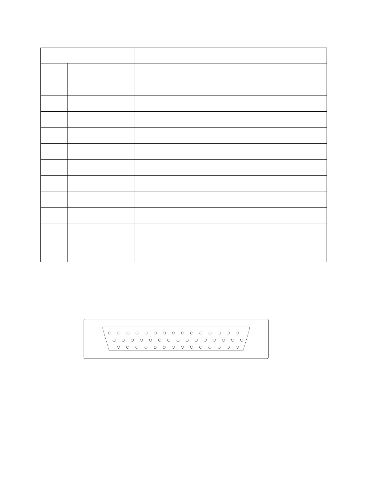
P1 Connector (continued from previous pa ge)
Pin # Name Signal Type (dependent on maintenance page selection)
41
27
12
42
28
13
43
29
14
44
30
IM
MM
OM
429 Out A
429 Out B
RS232TxD
WPT
MSG
ACT
ARM
Audio LL Out
Audio LL Low Level Audio output, requires external amplifier.
15
OBS/LEG
Note 1: 3 volt co mposi te i npu ts req uire t he use o f a s eri es resi st or. See i nst all ati on
drawings.
Note 2: For XYZ input s Z is si gn al g roun d P1-1.
Outside View
(Mating Connector )
82005-IM-R Sandel SN3500 Installation Manual Page 2-8
Page 28

2.5.2 Connect or P2
In Note: May be same or different than P1-16 inverter source.
Inverter 26Vac Excitation for items on connector P2
In
(RS232) Ground side
In
(RS232) Rx
In
(RS232) Ground Side
In
(RS232) Rx
ILS Energize1
Discrete In
In
Discrete Valid Discrete Open/Gnd or Open/+28Vdc
In
A710 Composite Video
In
A407 Synchro Y [Z grounded]
ILS Energize2
Discrete In
In
Discrete Valid Discrete Open/Gnd or Open/+28Vdc
In
A407 Synchro X [Z grounded]
In
A407 Synchro Y [Z grounded]
In
ADF Ref ADF DC, Note: Not used when 429 or XYZ is data source.
In
Discrete Valid ADF Discrete, Note: Not used when 429 is data source
In A429 A side 429
A710 Composite Video
In Note: For composite inputs see P2-42
(RS232) Rx
Pin # Name Signal Type (dependent on maintenance page selection)
Technical Information
16
1
31
17
2
32
18
3
Inverter Exc.
Shield Gnd
FMS 1A
FMS 1B
FMS 2A
FMS 2B
NAV1A
A429 A side 429
(RS422) + side 422
A429 B side 429
(RS422) - side 422
A429 A side 429
A429 B side 429
A429 A side 429
A407 Synchro X [Z grounded]
33
19
4
34
20
5
35
21
NAV1B
ADF 2A
TACAN 1A
ADF 2B
TACAN 1 B
ADF 2 DC Ref
ADF 2 Valid
NAV2A
NAV2B
A429 B side 429
A429 A side 429
A419 A side 419 (TACAN only)
DC Sin DC Sine (ADF only)
A429 B side 429
A419 B side 419 (TACAN only)
DC Cos DC Cosine (ADF only)
(RS422) + side 422
(RS232) Ground side
A429 B side 429
(RS422) - side 422
82005-IM-R Sandel SN3500 Installation Manual Page 2-9
Page 29

Technical Information
In
Analog DC+
In
Analog DC-
In
A568
In
Discrete Valid
OBS Resolver
DC Ref
In
Resolver DC
In
Resolver H
OBS Resolver
X/Sin out
Out
Resolver Out
OBS Resolver
Y/Cos out
Out
Resolver Out
Fluxgate
Excitation
In
Fluxgate Excitation
In
In
In
In 3rd inverter input used specifically if autopilot inverter is not
Out Locked to P1-16 or P2-10
Out Locked to P1-16 or P2-10
Out Bootstrap, locked to inverter on P1
P2 Connector (continued fro m previous pa ge)
Pin # Name Signal Type (dependent on maintenance page selection)
6
36
22
7
37
23
8
38
24
9
39
DME 1 DATA
DME 1 CLK
DME 1 SYNC
DME 1 Hold
OBS Resolver H
Fluxgate X
Fluxgate Y
A568
A568
25
10
40
26
11
Fluxgate Z (Gnd)
Hdg Crs/Datum
Excitation
Course Datum
Hdg Datum
Hdg X Out
inverter connected to P1-16 or is not 400Hz
82005-IM-R Sandel SN3500 Installation Manual Page 2-10
Page 30
Technical Information
Out Bootstrap, locked to inverter on P1
FCS ILS
Energize Out
Out Active Low
Out LL Out (gnd ref)
Out LL Out (gnd ref)
FCS Lat Dev
+RIGHT
Out LL Out (gnd ref)
FCS Vert Dev
+UP
Out LL Out (gnd ref)
FCS Lat
Superflag Out
Out Superflag Out
FCS Vert
Superflag Out
Out Superflag Out
Out RS232
Out
A429 A side 429
Out
A429 B side 429
15
30
44
14
29
43
13
28
42
12
27
41
11
26
40
10
25
39
9
24
38
8
23
37
7
22
36
1
16
6
21
35
5
20
34
4
19
33
3
18
32
2
17
31
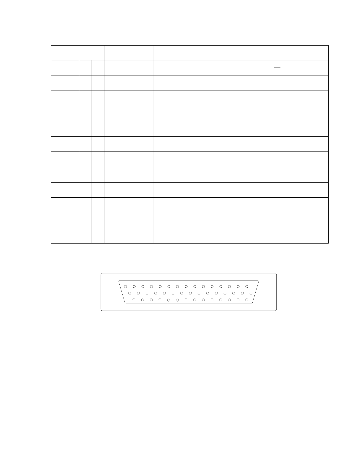
P2 Connector (continued fro m previous pa ge)
Pin # Name Signal Type (dependent on maintenance page selection)
41
27
12
42
28
13
43
29
14
44
30
15
Hdg Y Out
FCS Lat Flag+
FCS Vert Flag+
RS232-2 Out
Spare
429-2A
429-2B
Note 1: For XY Z input s Z is si gn al g roun d P1-1. For XYZ Outputs Z is pow er g roun d.
Outside View
(Mating Connector )
82005-IM-R Sandel SN3500 Installation Manual Page 2-11
Page 31

2.5.3 Conne ctor P3
In +22 to +33Vdc
Power
In
Power
GPS OBS/HOLD
TACAN Relay Out
(Out)
GPS APPR ARM
TACAN Relay Out
(Out)
In System Ground
In System Ground
GPS1 Relay
Sense / Selected
In
Discrete Valid
GPS2 Relay
Sense
In
Discrete Valid
NAV2 Relay
Sense
In
Discrete Valid
NVIS Ctrl
REV Control
In – Active Low
Analog DME Valid
REV Control
In
FCS BACK
COURSE
Out
(Open Drain)
Out
Open Drain
Out
Open Drain
Out
Open Drain
8
15714
1
6135124
11
3102
9
Pin # Name Signal Type (dependent on maintenance page selection)
Technical Information
1
9
2
10
3
11
4
12
5
13
Aircraft Pwr
Aircraft Pwr
or
or
Aircraft Ground
Aircraft Ground
or
(Open Drain)
(Open Drain)
Discrete
6
or
Discrete Valid
14
7
15
8
GPS1 Relay
GPS2 Relay
NAV2 Relay
Outside View
(Mating Connector )
82005-IM-R Sandel SN3500 Installation Manual Page 2-12
Page 32
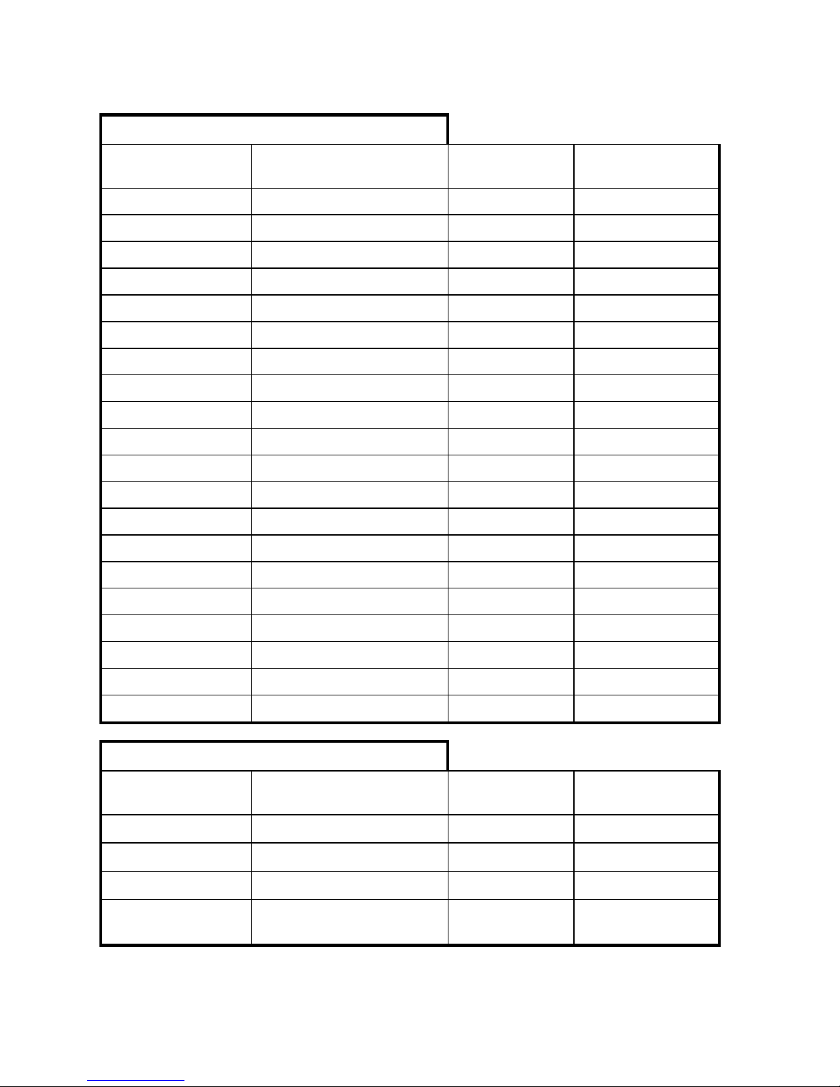
2.5.4 Signal C haracteri stics Tabl e
A429
+/- 5Vdc
100Vdc
>100K
A568
0 / +10Vdc
100Vdc
>100K
RS232
+/- 10Vdc
100Vdc
>100K
RS422
+/- 5Vdc
100Vdc
>100K
A710 (ILS)
.5Vac rms +/- 20%
70Vac
>100K
A711 (VOR)
.5Vac rms +/- 20%
70Vac
>100K
A407
0 to 11.8Vac
70Vac
>100K
DC SIN/COS
+/- 20Vdc
100Vdc
>100K
A407 (AC Synchro)
11.8Vac rms +/- 20%
100Vdc
>100K
ADF_REF
10Vdc +/- 50%
60Vdc
>100K
Alt DC Coarse
0 to 15Vdc
100Vdc
>100K
Analog DME
0 to 8Vdc
75Vdc
Note 5
180K
Discrete Valid (High)
>14.0Vdc
Note 4
60Vdc
>500K
Discrete Valid (Low)
<3.5Vdc
Note 4
40Vdc
>500K
Discrete (High)
>1.2Vdc
32Vdc
50K
Discrete (Low)
<8Vdc
32Vdc
50K
GS
+/- 225mv FS
60Vdc
>300K
Note 2
GS Flag
Unflagged > 225mv
60Vdc
>300K
Note 2
Inverter
26Vac rms
200Vac
>50K
Power
+22 to +33Vdc
Note 1
7Adc
NA
Inputs
Technical Information
Signal Type Nom Range Absolute Max
Note 3
Z (Ω – Power Off)
Outputs
Signal Type Nom Range Absolute Max
A429 +/- 5Vdc 70mAdc 2K (Minimum)
RS232
+/- 5Vdc
A575 3.54 mA +/-1% 25mA 500
Open Drain
1Ω or High Impedance (over
current protected)
82005-IM-R Sandel SN3500 Installation Manual Page 2-13
Note 3
70mAdc
Z (Ω – Power Off)
500 (Minimum)
250mAdc >350K
Page 33

Technical Information
Notes:
1. At +28Vdc, nominal curr ent i s 1.4Adc for lamp equipped unit s an d 1.2Ad c for LED equip ped un its, 1 minute after start u p.
2. Power On Load = 60 .4K. For G lide slope there may n eed to be a 1K l oad s omew here e lse i n the syste m to meet t he
receiver load requiremen ts. Check installation instructions for the interfaced receiver.
3. Outputs are protec ted ag ain st shor ts to ground . S hort s to p ower supply may c ause damag e to c ompo nents .
4. Discrete inputs ac tively pul led to 27.5v t hrough 30k ohms w hen s electe d ‘ac tive low ’ or act ively pu lled to 0v th rou gh 30 k
ohms when selecte d ‘act ive high ’ in th e mai ntenan ce pa ges. T his e nsure s th e inp ut is in the ‘ina ctiv e’ sta te if an ex ternal
connection fails. If i nter facin g to discre te si gnals which do not s upply a “ha rd” 0v/27. 5 vol t t ran siti on, any inpu t n etwor k
may be used that ensure s that the discre te input pin i s not w ith in 1.0v fr om it s nomin al t hresh old shown i n th e tab le eit her
in the active or i nactiv e st ate.
5. Value is for max imum n on-sustained input voltage, maximum sustained voltage is 10.8vdc.
82005-IM-R Sandel SN3500 Installation Manual Page 2-14
Page 34

2.6 ARINC 429
ADF
162
ADF Bearing
Gyro/ AHRS
155
Maintenance Words (Sandel SG102 Only)
270
AHRS Status Information (when available)
320
Magnetic Heading
324
Pitch
325
Roll
332
Lateral Acceleration
350
Maintenance Words (Sandel SG102 Only)
351
Maintenance Words (Sandel SG102 Only)
352
Maintenance Words (Sandel SG102 Only)
353
Maintenance Words (Sandel SG102 Only)
354
Maintenance Words (Sandel SG102 Only)
TCAS
013
Control Word for TCAS/Mode S
015
Altitude Select Limits for TCAS / Mode S
016
Control Word for TCAS/Mode S
130
Intruder Range
131
Intruder Altitude
132
Intruder Bearing
203
Altitude (1013.25 mB)
204
Baro Corrected Altitude
320
Magnetic Heading
371
General Aviation Equipment Identifier
377
Equipment Identification
357
Request To Send (RTS) / End Transmission (ETX)
NAV
034
VOR/ILS Frequency
173
Localizer Deviation
174
Glideslope Deviation
222
VOR Omnibearing
371
General Aviation Equipment Identifier
TACAN
201
TACAN Distance
202
TACAN Distance
222
TACAN Bearing
246
TACAN Station ID (Characters 1-2)
247
TACAN Station ID (Characters 3-4)
362
TACAN Range Rate
2.6.1 ARINC 419/429 Seri al Data Recei vers Int erfaces
The ARINC 419/429 serial data bus interface provides an information link between
the SN3500 and peripheral avionics equipment. The bus conforms to 419/429
specifications for electr i cal ch aract er isti cs, r ecei v ing , and tr ans missi on i nter val .
The SN3500 is capable of receiving the following ARINC 419/429 long-range NAV,
ADF, TCAS, or DME inputs for processing and displ ay as follow s:
LABEL DESCRIPTION
Technical Information
82005-IM-R Sandel SN3500 Installation Manual Page 2-15
Page 35

LABEL DESCRIPTION
DME
035
DME Frequency
202
DME Distance
GPS/FMS
076
GNSSS Altitude
100
Selected Course #1
114
Desired Track
115
Waypoint Bearing
116
Cross Track Distance
117
Vertical Deviation
121
Horizontal Command (Roll Steering Commands)
125
Universal Time Coordinated (UTC)
147
Magnetic Variation
150
Time
251
Distance To Go
260
Date
261
GPS Discrete Word (GAMA)
266
FMC Nav Mode
275
Status Word (GAMA)
310
Present Position – Latitude
311
Present Position – Longitude
312
Ground Speed
313
Track Angle – True
326
Lateral Scale-Factor
327
Vertical Scale-Factor
377
Equipment Identification
303
Message Length / Type / Num
075
Active Waypoint From / To Data
074
Flight Plan Header
275
Status Word (GAMA)
113
Message Checksum
300
Station Type, Class
304
Message Characters 1-3
305
Message Characters 4-6
306
Waypoint Latitude
307
Waypoint Longitude
340
L/R Procedure Turn Azimuth
335
L/R Holding Pattern Azimuth
330
Arc Inbound Course
331
Arc Radius
332
Arc Change Angle
Technical Information
82005-IM-R Sandel SN3500 Installation Manual Page 2-16
Page 36
Selected Course
(Using extended SDI)
320
Magnetic Heading
2.6.2 ARINC 419/429 Seri al Transmit ter Interf aces
The SN3500 is capable of transmitting the following low or high speed ARINC 429
data:
LABEL DESCRIPTION
100G
Technical Information
82005-IM-R Sandel SN3500 Installation Manual Page 2-17
Page 37

3 Installation
3.1 General
This section provides general suggestions and information to consider before
installing the SN3500 including interconnect diagrams, mounting dimensions and
information pertaining to installation. Close adherence to these suggestions will
assure optimum performance.
3.1.1 Unpacki ng and Insp ecting Equi pment
Exercise extrem e care when unpacking the equipment. Make a visual inspection of
the unit for evidence of damage incurred during shipment. If a claim for damage is to
be made, save the shipping container to substantiate the claim. The claim should be
promptly filed with the carrier. It would be advisable to retain the container and
packaging materi al a fter all eq uipme nt has be en remov ed in t he event t hat eq ui pme nt
storage or res hip ment s houl d bec om e necessary.
Installation
3.2 Installation Co nsiderations
3.2.1 General C onsiderations
The SN3500 should be installed in accordance with standards established by the
customer’s installing agency, and existing conditions as to unit location and type of
installation. However, the following consi der ati ons sho uld be heed ed be fore ins talli ng
the SN3500. Close adherence to these considerations will assure a more
satisfactory performance from the equipment. The installing agency will supply and
fabricate all external cables. The required connectors and associated hardware are
supplied by Sa ndel Av ionics .
3.2.2 Coolin g Considerat ions
The SN3500 Navigation Display contains its own ventilation fan for internal
component cooling and therefore, does not require a forced air cooling system. Any
questions concerning cooling can be verified in the post-installation checkout by
monitoring the SN3 500 Inter nal temp erature on the Sys tem mainte nanc e page.
3.2.3 Mechani cal Instal lation Co nsiderations
The SN3500 installation should conform to customer requirements and airworthiness
standards affecting the location and type of installation. §25.1321(a) stipulates that:
“Each flight, navigation, and power plant instrument for use by any pilot must be
plainly visible to him from his station with the minimum practicable deviation f rom his
normal positi on an d lin e of vi sion w he n he i s l ook ing f orw ard al ong the fli ght pa th.”
§ 25.1321(b) stipulates: “The flight instruments required by §25.1303 must be
grouped on the instrument panel and centered as nearly as practicable about the
vertical plane of the pilot’s forward vision.” In addition - §25.1321(b)(4) states: “The
instrument that most effectively indicates direction of flight must be adjacent to and
82005-IM-R Sandel SN3500 Installation Manual Page 3-1
Page 38

directly below the instrument in the top center position.” Similar regulations apply to
FAR Part 29 Tra nsp ort Categ ory Rotor cra ft and to Part 23 S mall Air pla nes.
Refer to Sandel Avionics, Drawing No. 82005 titled, “Layout - SN3500 Installation” for
specific assembl y and mounti ng instr uctio ns.
3.2.4 Electr ical Instal lation Considerations
Connections and functions of the SN3500 are described in this section. Refer to the
SN3500 Interconnect Wiring Diagrams for detailed wiring information and appropriate
notes. Refer t o t he F uncti onal Pinout Descr iptio ns for explan ations of pin functions.
A. The installing agency will supply and fabricate all wiring harnesses. The
length and routing of wires must be carefully measured and planned before
the actual installation is attempted. Avoid sharp bends in the harness or
locating the harness near aircraft controls. Observe all recommended wire
sizes and types a nd su bscr ibe t o appr opr iat e FAR Par ts 2 3, 25, 2 7, a nd 29 , as
well as AC 43.13-1( ) and -2( ).
Installation
B. The use of MIL-C-27500 shielded wire and MIL-W-22759 single conductor
wire is recommended. The use of ferrules or grounding blocks for signal
ground and digital ground returns is satisfactory, however, each ground return
must be electri cal ly sep arate d.
C. When an existing installation of a navigation source selection relay unit is
installed to provide mode control switching and annunciation for a GPS or
other long-range navigation system, the SN3500 may not perform these
functions simultaneously. This does not preclude the SN3500 from
annunciating s uch mod e contr ol func tio ns.
D. In order to ensure optimum performance the SN3500 and associated wiring
must be kept at leas t a minimum of three feet from high n oi s e s our c es and not
routed with c ables fro m hig h pow er s ourc es.
E. Prior to installing the SN3500, a point-to-point continuity check of the wiring
harness should be accomplished to verify proper wiring. See FUNCTIONAL
GROUND TEST PROCEDURES/REPORT in the appendix for verification of
this step and other chec ks .
F. The Functional Pinout Descriptions on the following pages will assist you in
determining installation requirements. Adhere to all notes within these
descriptions and on installation wiring diagrams.
G. Special caution must be taken to observe 30 Hz OBS r esolv er connec t ions i n
order to prevent possible damage to the installed V OR/l ocal iz er conv erter .
See Installation Wiring Diagrams and the MAINTENANCE MENU,
Configuration Ins tructi o ns for n otes per tai ning t o t hes e cons ider ati ons.
82005-IM-R Sandel SN3500 Installation Manual Page 3-2
Page 39

Installation
H. Ground Bonding. In order to assure installation characteristics match the
DO-160 RF and Lightning test conditions, ensure that two ground wires of at
least the recommended size are installed in accordance with the installation
drawings and these wires are connected to a bonded aircraft ground. Ensure
that shielded w ir i ng i s used to t he F l ux Gate (if installed), Gyro Re fere nce, and
Gyro XYZ ( if install ed) .
I. Power Wiring. To assure that the SN3500 will operate properly down to its
rated minimum input voltage of 22Vdc, ensure that two power wires of at least
the recommended size are connected from the SN3500 circuit breaker to the
SN3500 in accor danc e wi th the i nstal lat ion dra w ing s.
82005-IM-R Sandel SN3500 Installation Manual Page 3-3
Page 40

3.3 Signal Details
The following information is in the same order as the summary pin description list
in the prior sec ti on.
3.3.1 Conne ctor P-1 Pinout Description
P1-1: Signal Ground Return Input
This common Signal Ground Return is used for P1 analog signal grounds
such as the Z lead of synchros, and analog signal shield grounds. See the
installation wiring diagrams for details. Do not use this pin to connect digital
signal ground return shields or use t his for pow er g roun d ret urn.
P1-16: Primary AC Excitation Input for P1 inputs
Connection to this pin is required only if functions of ARINC 407 synchro or
400Hz AC sine and cosine inputs are used on P1. NOTE: This is also the
reference for synchro referenced outputs on the opposite connector P2.
The input requirements are 26Vac nominal 400Hz. Input frequency is 560
Hz. maximum and 240 Hz. minimum. Input impedance is 220KΩ. 24 AWG
shielded wire is rec ommend ed for this f unction.
Installation
P1-31: TCA S 429 A
P1-17: TCAS 429 B
Optional ARINC 429 in put for traffi c.
P1-2: Data l ink A
P1-32: Data link B
Optional input for F IS-B data link (Softwar e Rev . 3. 0 and abov e).
P1-3: Hdg X; Hdg 429A; DG Stepper A Input
P1-33: Hdg Y; Hdg 429B; DG Stepper C Input
Master HDG inp uts.
For XYZ type directional gyro, ground the Z leg to signal ground P1-1. This
input is referenced to the 26Vac/400Hz reference on P1-16. This function is
selected on th e C ompas s mai nten anc e pag e.
Stepper connections are used exclusively for connections to the Bendix/King
KG-102 or Mid-Continent series Directional Gyro when selected in the
Compass maintenance page. For slaved operation see fluxgate descriptions.
24 AWG twisted shiel de d pai r w ir e is r ecomm ended for this co nnec tio n.
P1-19: Hdg Valid Input
Connect to the (DG) valid output if available. Not used for 429 sources.
Selection of th e l ogi c le v el of t his pi n is in the C om pass maint enanc e pag e.
P1-4: ADF-1 AC-X or DC-SIN Input / TA CA N 2 429 /419 A
P1-34: ADF-1 AC-Y or DC-COS Input / TACAN 2 429419 B
82005-IM-R Sandel SN3500 Installation Manual Page 3-4
Page 41

Inputs from ADF-1 Receiver. Selection of AC/DC operation is on the ADF
maintenanc e page. For DC use P1-20 as the DC reference input. For AC
inputs Z is grounded. 24 AWG twisted shielded pair wire is recommended for
these functions.
P1-20 ADF-1 DC Ref
Used when DC SIN /C OS i nputs are us ed
P1-5 ADF-1 V alid
Discrete ADF V ali d inpu t us ed i f av ailabl e.
P1-35: WX500 Ground
P1-21: WX500 RS232
Connection to WX-500 Stor msc ope . Us e 2 4AWG tw i sted p air .
P1-6: Glideslope +FLAG
P1-36: Glideslope -FLAG
Low level GS receiver flag inputs. Superflags can be supported with a
resistor, see the i nstal l ati on dr awi ngs .
Installation
P1-7: Glideslope +UP Deviation Input
P1-22: Glideslope +DOWN Deviation Input
GS deviation input. Two-dot deflection is ±150 mVdc. 24 AWG twisted
shielded pair wir e is recommend ed for th ese functi ons.
P1-37: VOR-LOC +FLAG
P1-23: VOR-LOC -FLAG
Used when an external NAV converter or analog output GPS is used.
Differential Low level NAV Flag inputs. Superflags are supported with a
resistor, see the installation drawings. Flag out of view requires greater than
215 m
Vdc on +FLAG with respect to -FLAG input. 24 AWG twisted shielded
pair wire is r ecom mend ed for t hese func tio ns.
P1-8: VOR-LOC +RIGHT Dev iation Input
P1-38: VOR-LOC +LEFT Deviation Input
Used when an external NAV converter or analog output GPS is used. Analog
lateral deviation from the VHF navigation receiver or long-range navigation
receiver +LEFT and +RIGHT deviation outputs. Two-dot deflection is ±150
m
Vdc. 24 AWG twisted s hi elded pair w ire i s rec o mmende d f or t hese fun ctions .
P1-24: VOR +TO Pointer Input
P1-9: VOR +FROM Pointer Input
Used when an external NAV converter or analog output GPS is used.
Differential input supports VHF NAV or long-range navigation +TO pointer and
+FROM pointer outputs. In-view is greater than 40 mVdc (to) and –40mVdc
(from). 24 A WG tw ist ed shi el ded pair w i re is reco mmen ded func tio ns.
82005-IM-R Sandel SN3500 Installation Manual Page 3-5
Page 42

P1-39: DME 2 CLK/429A
P1-25: DME 2 Data/429B
P1-10: DME 2 Sync
ARINC 568 Sync or King Clk/Data/Sync (DME REQ) signal input. NOTE:
This is DME 2.
P1-26: External Brightness Control
Broken Wire Detection
0 to 0.5VDC, revert to internal contr ol.
Full Dim
1.5VDC
Full Bright
14V Aircraft: A/C p ow er min us 2 VDC
28V Aircraft: A/Ct power minus 4VDC
P1-40: DME 2 Hold
Discrete HOLD i npu t si g nal for on-screen annunciator
P1-41: Inner Marker Beacon Input
P1-27: Middle Marker Beacon Input
P1-12: Outer Marker Beacon I nput
Marker beacon receiver inputs. Normally connected to the external lamp
drivers on the marker beacon receiver, see the installation drawings. Most
marker beacon receivers use “DC” ground referenced outputs driven by
transistor drivers. All such receivers are compatible as shown on the
installation drawings. Some very old designs may use transformer outputs
which are AC co uple d. Thes e may no t b e com pati ble.
Installation
P1-42: ARINC1 429-A Output
P1-28: ARINC1 429-B Output
Low or high spe ed A RI NC 429 outp ut, sp are. ( Future us e.)
P1-13: Ch1 RS-232 TX Output
RS-232 serial data outputs. TXD-2 is used to support W X-500 Stormscope® .
24 AWG shield ed wi re i s req uired for eac h of t h ese f uncti ons .
P1-43: WPT A nnunciator input
P1-29: MSG A nnunciator input
P1-14: ACT (Approach Active) Annunciator Input
P1-44: ARM (Approach Arm) Annunciator Input
Active-low inputs for GPS/LRN on-screen an nunci ators.
P1-15: OBS-/LEG, HLD-/AUTO or PAR TRK- Annunciator Input
For selected GPS-1 receiver with OBS/LEG mo de (or HO LD/AU TO), thi s inpu t
when low senses and annunciates OBS or HOLD on the SN3500 display and
changes the mode of the course pointer from auto-slew to manual control.
Otherwise, thi s is us ed as a PAR TRK i nput for other types of recei v ers, base d
on the selection in the L NAV maint enance pag e.
82005-IM-R Sandel SN3500 Installation Manual Page 3-6
Page 43

P1-30: Audio Out
LL audio output to the audio panel for optional cal lout s al er ts . ( Future use, not
currently supp orte d.)
3.3.2 Conne ctor P-2 Pinout Descriptions
P2-1: Signal Ground Return Input
This common Signal Ground Return is used for P2 analog signal grounds
such as the Z lead of synchros, and analog signal shield grounds. See the
installation wiring diagrams for details. Do not use this pin to connect digital
signal ground r etur n s hiel ds or us e thi s for p ower gr ound r etur n.
P2-16: AC Excitation Input for P2 inputs
Connection to this pin is required only if functions of ARINC 407 synchro or
400Hz AC sine and cosine inputs on P2. It does NOT apply to outputs on
P2. The input requirements are 26Vac nominal 400Hz. Input frequency is
560 Hz. maximum and 240 Hz. minimum. Input impedance is 220KΩ. 24
AWG shielded w ir e is r ecom mend ed for thi s fun ction.
Installation
P2-31: GPS1/FMS 1 429A/422+ /232 Gn d
P2-17: GPS1/FMS 1 429B/422-/ 232 Sig nal
Main input from GPS/F MS 1.
P2-2: GPS2/FMS 2 429A/422+/232 Gnd
P2-32: GPS2/FMS 2 429B/422-/ 232 Sig nal
Main input from GPS/F MS 2.
P2-18: VHF Nav-1 ILS Energize Input
This pin controls the Vertical Deviation Bar when selected to NAV1. These
signals also control the ILS Lockout logic so the SN3500 can sense when a
GPS receiver is inappropriately selected as the primary NAV source when ILS
Lockout is not disabled on the NAV maintenance page. Connec ti ons t o th e se
pins are from the respective VHF navigation receiver and optionally by the
GPS receiver. The logic level of these inputs is selected on the NAV
maintenance pag e, a nd i s nor mally active-low.
P2-3: VHF NAV1 429A/Composite
P2-33: VHF NAV1 429B
Primary 429 input from VHF NAV1, or composite input from analog receiver
for VOR bearing pointer. Composite is normally .5v VOR / .33v LOC. For 3V
inputs a series resistor is required, see the installation drawings. W hen using
the composite input for LOC deviation, the calibration procedure found in
section 7.1.5 must be followed for each specific LOC input. 24 AWG shielded
wire is recommended for these connections. Note: When using the composite
signal for the localizer deviation input, the calibration procedure found in
section 7.1.5 must be p erfor med after th e instal lation prior to rel ease for flight.
82005-IM-R Sandel SN3500 Installation Manual Page 3-7
Page 44

P2-4: ADF-2 AC-X or AC/DC-SIN Input / TA CA N 1 429 /419 A
P2-34: ADF-2 AC-Y or AC/DC-COS Input / TACAN 1 429/419 B
Inputs from ADF2 Receiver. Selection of AC/DC operation is on the ADF
maintenanc e page. For DC use P2-20 as the DC reference input. For AC
inputs Z is grounded. 24 AWG twisted shielded pair wire is recommended for
these functions.
P2-20: ADF2 DC Ref
Used when DC Sin /Cos i nputs are use d.
P2-5: ADF2 Valid
Discrete ADF V ali d inpu t us ed i f av ailabl e.
P2-19: VHF Nav2 ILS Energize Input
Control the ena bli ng o f the Vert ic al Dev iat ion B a r w hen NAV 2 s elect ed
P2-35: VHF NAV2 429A/Composite
P2-21: VHF NAV2 429B
Primary 429 input from VHF NAV2, or composite input from analog receiver
for VOR bearing pointer. Composite is normally .5v VOR / .33v LOC. For 3V
inputs a series resistor is required, see the installation drawings. W hen using
the composite input for LOC deviation, the calibration procedure found in
section 7.1.5 must be followed for each specific LOC input. 24 AWG shielded
wire is recommended for these connections. Note: When using the composite
signal for the localizer deviation input, the calibration procedure found in
section 7.1.5 must be p erfor med after th e instal lation prior to rel ease for flight.
Installation
P2-6: DME1 Data, Analog DME DC+/429A
P2-36: DME1 CLK, Analog DME DC-/429B
P2-22: DME1 Sync
P2-7: DME1 Hold
Serial data inputs for either ARINC 429 / 568 serial protocols to support
ARINC DME’s as selected within the DME Maintenance page (Low speed
only), Bendix/King DME’s using King Serial Digital protocol. See the
installation dr aw ings . 24 A WG twi sted s hiel ded tripl e co nductor is r equi r ed for
these functions. Note: This is DME1.
Analog DME in put ( 40m V/mil e) may al so be us ed.
P2-37: OBS Resolver DC ref Input
P2-23: OBS Resolver H Input
P2-8: OBS Resolver SIN Output
P2-38: OBS Resolver COS Output
OBS resolver connections for NAV or GPS receivers. The input frequency
range is 20Hz to 500Hz, and calibration is done on the NAV maintenance
page. The resolver is electrically zeroed at zero degrees plus the calibration
value in the NAV maint ena nc e pag e. For normal use this calibration value will
be –60 degrees (equaling 300 degrees electrical zero). This is the factory
82005-IM-R Sandel SN3500 Installation Manual Page 3-8
Page 45

default. A different calibration value setting is used for each possible NAV
source selectable on the SN3500. 24 AWG twisted shielded pair conductor is
recommended f or th es e functions. Please see the w ar ni ng s on the installation
drawings concer ni ng DC REF, whi ch must n ot be i nadv er tentl y g roun ded. .
P2-24: Flux Gate Excitation Input
This connectio n is mad e t o the 400 H z AC flux gate ex ci tati on so urc e vol tage.
A 24 AWG shiel ded w ire i s rec o mmende d f or t his functi on. No te: t he phas e
of this exci tation v oltag e is not req uire d t o be the s ame as th at suppl ie d to the
Primary AC Exc itati on inpu t on P1 or P2.
P2-9: Flux Gate X Input
P2-39 Flux Gate Y Input
P2-25: Flux Gate Z Input
Referenced to P2-24 Excitation input. Connections to these pins are made
directly from the heading system flux gate if internal slaving is selected on the
compass maintenance page. If a Bendix/King KI-525 PNI or Rockwell/Collins
331A-3( ) HSI is being removed, the respective slaving accessory, should be
bypassed. See the installation drawings for details. 24 AWG twisted shielded
triple conduct or i s rec om mende d for t hese s ignal s.
Installation
P2-10: HDG/CRS Datum Excitation
This is a ground referenced 400-5Khz excitation input for the HDG Datum and
CRS Datum outputs only. This input is only used if referenced on the
applicable inst all ati on dr aw ing . If u nus ed, Connect P2-10 to 28v dc P 3-1.
P2-40: Course Datum Output
P2-26: Heading Datum Output
These function ar e ei th er AC or DC Cours e D atu m and He ading Da tum for the
flight control system. If AC signals, the excitation reference is P2-10.
Selection of AC/DC, gain, and direction of rotation are accomplished on the
FCS maintenance page. 24 AWG single conductor shielded wire is
recommended for eac h of thes e functio ns.
P2-11: HDG Bootstrap X out
P2-41: HDG Bootstrap Y out
Z Ground. NOTE: Referenced to P1-16. This function may be used to
provide “bootstrap” output to an RMI or other directional instrument in the form
of ARINC 407 s y nc hr o 24 AWG twisted shielded p ai r wire is recommended for
these functions. Drive only electronic loads with this output – limited to 60ma
max.
P2-27: FCS ILS Energize Out
Active-low open drain output to FCS when selected navigation source vertical
deviation is e nabl ed.
P2-12: FCS Lateral Flag Output+
Low Level flag output derived from selected NAV source, referenced to
Ground. Conn ect c orre spon ding ‘-‘ input to P2-1 (Gnd)
82005-IM-R Sandel SN3500 Installation Manual Page 3-9
Page 46

P2-42: FCS Vertical Flag Output+
Low Level flag output derived from selected NAV source, referenced to
Ground. Conn ect c orr espo ndi ng ‘ -‘ input to P2-1 (Gnd)
P2-28: FCS Lateral Deviation Output +Right
LL lateral +deviation from selected NAV source. Connect corresponding ‘-‘
deviation input to P2-1 ( Gnd)
P2-13: FCS Vertical Deviation Output +UP
LL vertical +deviation from selected NAV source. Connect corresponding ‘-‘
deviation input to P2-1 (Gnd)
P2-43: FCS Lateral Superflag Output
Superflag out put d eri ved from s elec te d NAV so urce.
P2-29: FCS Vertical Superflag Output
Superflag out put d eri ved from s elec te d NAV so urce.
P2-14: RS-232 TX Output2
RS-232 serial FIS-B data link output (S oftw are Rev 3.0 and a bov e).
Installation
P2-30: ARINC2 429-A Output
P2-15: ARINC2 429-B Output
Low or high speed ARINC 429 output which transmits selected course and
selected heading for ARINC 429 Long Range NAV receivers. 24 AWG
twisted shiel ded pair w i re is req uir ed for t hes e func ti ons.
3.3.3 Conne ctor P-3 Pinout Descriptions
P3-1 &
P3-9: Display Primary Power Input
(22-33Vdc). Connectio n to b ot h pi ns is r equi r ed usi ng tw o 20AWG w ires a nd
a 5 ampere circ uit br eak er . Max im um p ower req uired i s 35 wat ts. Conn ecti on
to the avionics bus is rec ommend ed to r educe vol tage fluct uati ons d uri ng
engine start.
P3-3 &
P3-11: Display Power Return Input
Pins 3 and 11 ar e t he ai r craft grou nd i nput con nec tio ns. Connec ti on t o bot h
pins is requir ed us ing t wo 2 0 AWG wi res. Eit her pin s ho uld al so be us ed for
the digital sig nal gr ound (shi elds) r etur n, as req uir ed. The n umber o f sh ields
will vary depending up o n the func tio ns w ir ed to Conn ect or P3 .
P3-2: GPS OBS- or HOLD- Command Discrete Output or TACAN Relay Out
Open Drain activ e-low output used to operate th e OBS func tio n of Be ndi x/ King
KLN-90 GPS receivers or the HOLD function of the II Morrow and Garmin
GPS receivers. Accessible during normal use from the pilots GPS MODE soft
key.
82005-IM-R Sandel SN3500 Installation Manual Page 3-10
Page 47

Can also be used to operate a switching relay, or external annunciator
whenever a TACAN is selected by the NAV pushbutton. The TACAN
receiver(s) are co nfig ur ed on th e NAV maint enance pages.
P3-4: GPS1 Relay Sense / GPS SELECTED In put
This input is used when the SN3500 is set up for slave mode so an external
GPS switch can be used to switch to an external GPS receiver. Causes
proper mode switching and annunciation on the SN3500 display. This input is
active only w hen en able d in the O BS / RE LAY / CD I mai nten anc e pag e 10.
P3-5: NAV2 Relay Sen se
Feedback from NAV2 relay, if used. When replacing a SN3308 with the
SN3500, see configur ati on page 7-14.
P3-6: Analog DME Valid or REV Control
Discrete input for Anal o g D ME v alid or Rev ers ionary Di splay On /OFF contr ol .
For Reversionary Attitude Display units the Reversionary Display is enabled
by a closure to ground through an external toggle switch or maintained
pushbutton switch.
Installation
P3-7: GPS1 Switching Relay Discrete Output
Can be used to operate a switching relay whenever GPS1 (or Loran1) is
selected by the NAV pushbutton. The receiver type is selected on the LNAV1
maintenance pag e.
P3-8: VHF NA V2 S witching Rel ay D iscrete Output
Can be used to operate a switching relay whenever VHF NAV2 is selected by
the NAV pushbut ton . V HF NAV2 is e nabl ed o n th e NAV 2 maint enanc e pag e.
P3-10: GPS APPR ARM Discrete Output or TACAN Relay Out
Open Drain active-low output used to select APPR ARM mode of the external
GPS receiver. Accessible during normal use from the pilots NAV menu
operation.
Can also be used to operate a switching relay, or external annunciator
whenever a TACAN is selected by the NAV pushbutton. The TACAN
receiver(s) are configured on the NAV mainte nance pag es.
P3-12: GPS2 Relay Sense
Feedback from GPS2 r el ay , i f used.
P3-13: NVIS Ctrl or REV Control
For NVIS capable units NVIS mode is enabled by a closure to ground through
an external toggle switch or maintained pushbutton switch. NVIS mode is
annunciated ons cr een s o a n exter nal an nunc iat or is not r eq uired.
82005-IM-R Sandel SN3500 Installation Manual Page 3-11
Page 48

For Reversionary Attitude Display units the Reversionary Display is enabled
by a closure to ground through an external toggle switch or maintained
pushbutton sw itch.
The input wil l alw ay s pul l up to th e de-activated state when disco nnect ed.
P3-14: AFCS Back Course Discret e Outp ut
Open Drain. Used to feed the back course sensing input of an AFCS. When
the Course Select rotates either direction passing 90º clockwise or
counterclockwise from the lubber line of the SN3500 will generate an opendrain closure. An external relay may be required to make this signal activehigh.
P3-15: GPS2 Switching Relay Discrete Output
Can be used to operate a switching relay whenever GPS2 (or Loran2) is
selected by the N AV pu shbu tton. The r ec eiv er ty pe is s elect ed on t he LNAV-2
maintenance pag e.
Installation
82005-IM-R Sandel SN3500 Installation Manual Page 3-12
Page 49

4 Setup Procedures
4.1 General
Setup procedures for the SN3500 are described along with the Maintenance Menu
below. The Maintenance Menu is accessed and addressed through the use of
pushbuttons and the Selected Heading knob. No external connector pin
programming is r eq uir ed.
4.2 Accessing the M aintenance Menu s
To access the M ain tena nce M enu s per for m the f ollow ing oper atio ns:
A. Prior to applying power to the SN3500, depress and hold the [BRG] and the
[MEM] pushbuttons, then apply power to the unit. Continue to hold until the
first maintenance menu appears. This protocol insures that maintenance
menus cannot be cal le d up accid en tally dur ing fli ght.
Setup Procedures
B. Once the Maintenance Menu is entered, press the [NEXT] or [PREV] softkeys
to cycle the MAINTENANCE MENU pages. Use the UP/DOWN arrow keys
for selections, and rotate the right knob to adjust and select. On some menus
additional so ft key l egen ds w ill appear as pr om pts .
C. Escape the maintenance menus by pressing and holding the course pointer
knob (left knob). This will allow normal operation of the unit to test the effects
of settings. Re-enter the maintenance pages pressing and holding the course
pointer knob ( lef t knob) .
D. To disable maintenance menu operation, power down and restart normally.
All configured ite ms are store d in non-volatile memory.
4.3 Equipment/Config uration Selection s
The choices of compatible equipment contained in the SN3500 menus are listed in
the Appendix. F or ty pes no t li ste d, co nsul t th e f actory .
82005-IM-R Sandel SN3500 Installation Manual Page 4-1
Page 50

5 Operating Details
For an explanation of the operating details of the SN3500, r efer to the Pilo t’s Guide
for the SN3500, Sandel Avionics P/N 82005-PG, and to the Airplane Flight Manual
Supplement.
The SN3500 may utilize either an LED li ght s our ce or a l am p lig ht s ourc e. T he pi lots
guide (P/N 8200 5-PG, revision F or later ) sho ul d be r efer enc ed for l ight sour c e
identification an d ap plic able da ta color co ding in forma tion .
Operating Details
82005-IM-R Sandel SN3500 Installation Manual Page 5-1
Page 51

6 Instructio ns F or Continued A irworthiness
6.1 General
The following is a summary of the Instructions for Continued Airworthiness prepared
under the guidelines of FAA Advisory Circulars 23.1309-1( ) and 25.1309-1( ) which
identifies potential failure modes of the Sandel Avionics Model SN3500 Navigation
Display. The assumption made is that all functions of the SN3500 will be used in an
essential (pr imary ) nav ig ation fu nctio n.
Replace the SN3500 backlight lamp, when necessary, utilizing instructions in
the SN3500 Component Maintenance Manual, document number 82005-
0133.
Instructions For Continued Air worthiness
82005-IM-R Sandel SN3500 Installation Manual Page 6-1
Page 52

Appendix A: Post-Ins talla tion Proc edures
7 Appendix A: P ost-Installation Procedures
After all wiring has been verified and the SN3500 has been installed into the panel,
the maintenance pages must be accessed to properly configure the SN3500 for the
installed equipment. Prior to applying power to the SN3500, depress and hold the
[BRG] and the [MEM] keys, and then apply power to the unit. Continue to hold until
the first maintenance menu appears. This protocol insures than maintenance menus
cannot be called up acci dental ly during flight .
Once the Maintena nce Menu is enter ed, pres s the [ NEX T] or [LA ST] s oftk ey s to cy cle
the MAINTENANCE MENU pages. Use the UP/DOWN arrow keys for selections,
and rotate the right knob to adjust and select. On some menus additional soft key
legends wil l appe ar as pr ompts.
Escape the maintenance menus by pressing and holding the CRS knob. This will
allow normal operation of the unit to test the effects of settings. Re-enter the
maintenance pag es pr e ssi ng an d hol di ng th e C RS kn ob.
To disable maintenance menu operation, power down and restart normally. All
configured it ems w il l be store d in non-volatile memory.
NOTE: When conf iguring ARINC 429 inputs, select ‘429’ for low-speed and ‘429H’
for high-speed.
Each maintenance page, the options for each, and a brief description of each option
are detailed b elow :
82005-IM-R Sandel SN3500 Installation Manual Page 7-1
Page 53
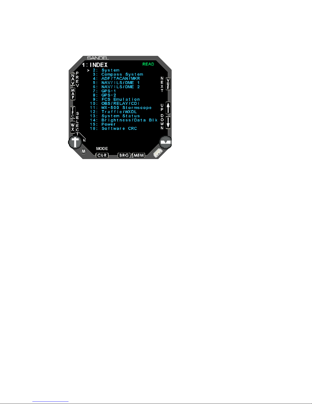
7.1.1 Page 1: INDEX
Appendix A: Post-Ins talla tion Proc edures
The Maintenance Index page is a multiple-choice list that provides an index of all
other maintenance pages and allows the operator to jump to a particular page. First
scroll the Cursor to point to the desired maintenance page listing using the [UP] Soft
key or [DOWN] Soft key. The [SELECT] Soft key is then pressed to jump to this
page. Once in the maintenance pages, press the [OPER] Soft key to return to the
Maintenance Index page. The [PREV] or [NEXT] Soft keys may also be used to
reach a partic ular mai ntena nce pag e seq uen tial ly .
The [MODE] Soft key is used to toggle the SN3500 between READ and EDIT mode.
Note: The SN3500 must be in EDIT mode to make configuration changes on the
following main tena nce pages.
82005-IM-R Sandel SN3500 Installation Manual Page 7-2
Page 54
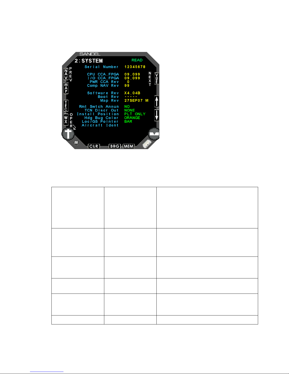
Rmt Switch Annun
NO
Set to yes to allow SN3500 to control
GPS switch inputs (LEG/OBS
switching, APPR ARM etc.) through
Pilot’s Menu. Available options will
depend on the model of GPS selected
on the GPS maintenanc e page.
TCN Discr Out
None
Selects which pin connector pin is
Install Position
PLT ONLY
COP DUAL
Set to adjust color of on-side/cross-side
Hdg Bug Color
Orange
White
Heading bug c olor s ele cti on.
Loc/GS Pointer
Bar
Selects style of Loc/GS pointer. With
Triangle Loc/GS pointers selected,
inner VDI wil l not be di spl ay ed.
Aircraft Ident
7 characters
Enter aircraf t id enti ficati on for r efer ence .
7.1.2 Page 2: SYSTEM
Appendix A: Post-Ins talla tion Proc edures
The System page provides information that identifies the unit and the unit’s hardware
and software.
Configuration Fiel d Options Comment
YES
P3-2
assigned to TACAN R el ay Out Si gnal .
P3-10
PLT DUAL
NAV informati on.
82005-IM-R Sandel SN3500 Installation Manual Page 7-3
Triangle
Page 55
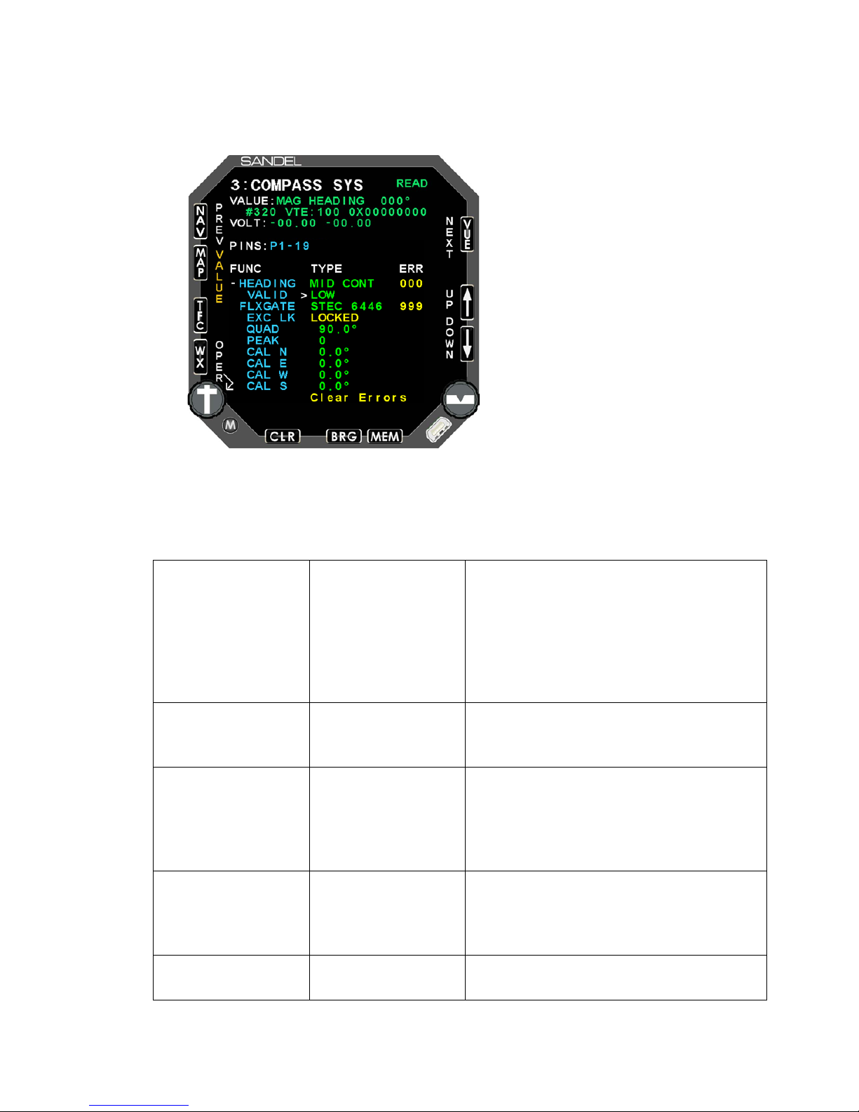
HEADING
NONE
KG102
Selects the gy ro i nput to the SN 350 0.
VALID
NONE
LOW
Not shown if 42 9 or 4 29 H i s s elected for
FLXGATE
NONE
STEC 6446
Selects model of fluxgate input when
QUAD
0.0°
270.0°
Set automatically when fluxgate is
PEAK
0 - 7
Set automatically when fluxgate is
selected
7.1.3 Page 3: COMPASS SYSTEM
Appendix A: Post-Ins talla tion Proc edures
The Compass System page configures the gyro and fluxgate (if applicable) to the
SN3500.
Configuration Fiel d Options Comment
429
429H
XYZ
XYZMID CONT
HIGH
KMT112
heading.
slaving is per for med in t ernall y.
COLLINS
HONEYWELL
82005-IM-R Sandel SN3500 Installation Manual Page 7-4
90.0°
180.0°
selected.
Page 56

Appendix A: Post-Ins talla tion Proc edures
CAL N
CAL S
-25.0° - 25.0°
Calibration settings for fluxgate input.
CAL E
See below.
CAL W
7.1.3.1 Compass Calibration (Applies to installations using a fluxgate input)
When a flux gate is first selected the quadrant and peaking adjustments will be
automatically set.
The magnetic heading shown in the value field at t he t o p o f the page should be within
+/-20° of the aircraft’s wet compass reading. The magnetic heading reading should
also increase and decrease as appropriate when the aircraft is turned. If this is not
the case, the following troubleshooting procedure can be used to diagnose fluxgate
problems:
a) Align the aircraft to north. Set the CAL settings to 0.0°. Adjust the
quadrant setting until the magnetic heading is +/-20° of nort h. If it is not
possible to come within +/-20° of north then the XYZ connections the
fluxgate may actually be ‘YZX’ or ‘ZXY’. Take all three wires off the
fluxgate and move them one terminal ‘clockwise’ and retest as above. It
may be necessary to repeat this step. Once the magnetic heading reads
within +/-20° of north then the correct Z leg has been identified and should
not be change d
Note: When inst al l ing to existing wiring, ens ure t h at the fluxgate center tap
that exists on some Honeywell/Sperry and Collins fluxgates is not
connected.
b) Ensure that the compass card rotation is correct by observing that the
magnetic heading reading increases/decreases properly as the aircraft is
turned. Reverse the XY inputs from the fluxgate to correct for reverse
rotation if nec ess ary .
Compass calibration is completed by aligning the aircraft at each cardinal heading
and adjusting the corresponding calibration value until the magnetic heading reading
observed on the compass maintenance page, matches the actual aircraft heading.
After the four cardinal points have been adjusted and verified, a final check of the
systems should be done by power cycling the SN3500 into normal mode and
ensuring the co mpas s r ose is cor rect f or e ach c ardin al h eadi ng.
NOTE: Changes to the compass calibration settings may take up to two m inutes to
take effect when observing the compass card in normal operational mode. Therefore
It is recommended to make these calibration adjustments on the compass
maintenance page where the compass readings are instantaneous and not affected
by the slaving logi c in t he SN3500 .
82005-IM-R Sandel SN3500 Installation Manual Page 7-5
Page 57
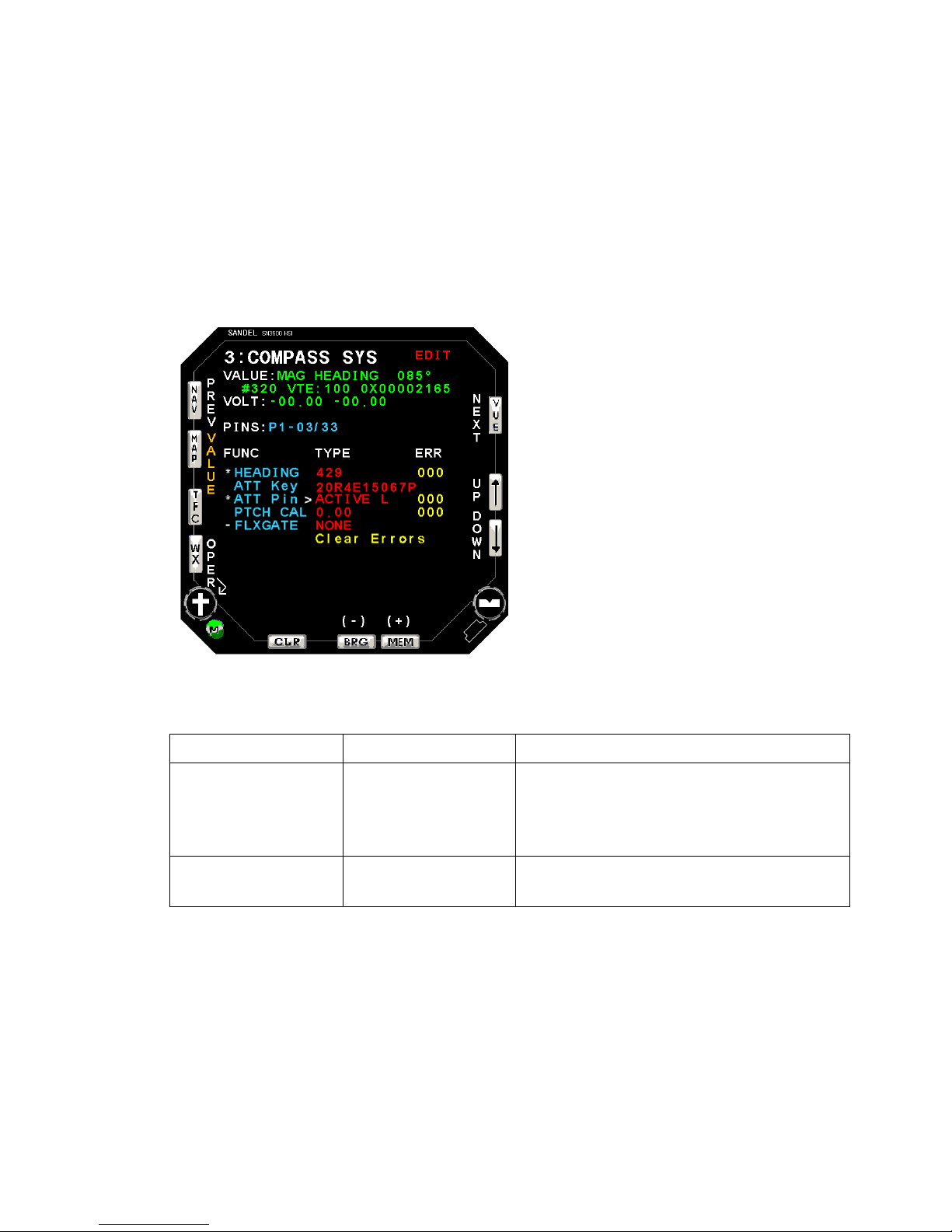
Appendix A: Post-Ins talla tion Proc edures
ATT Key
Enter the Rev ersi onary atti tud e key .
ATT Pin
None
Connector pin values do not appear in
the ATT Pin selection field. The appear
above in the PINS fiel d.
PTCH CAL
d.dd
Pitch Adjustment of Reversionary
Attitude displ ay + /- 5.00
Reversionary Attitude Configuration (ARINC 429 Low/High speed only)
When the HEADING source is configured as ARINC 429, an optional Reversionary
Attitude Mode is available for activation via a valid key entry. Once configured and
valid, The assigned input discrete connected to an external switch controls the
switching betw een HSI Mode and Reversionary Attit ud e Mode .
Configuration Fiel d Options Comment
Active L (P3-6)
Active L (P3-13)
82005-IM-R Sandel SN3500 Installation Manual Page 7-6
Page 58
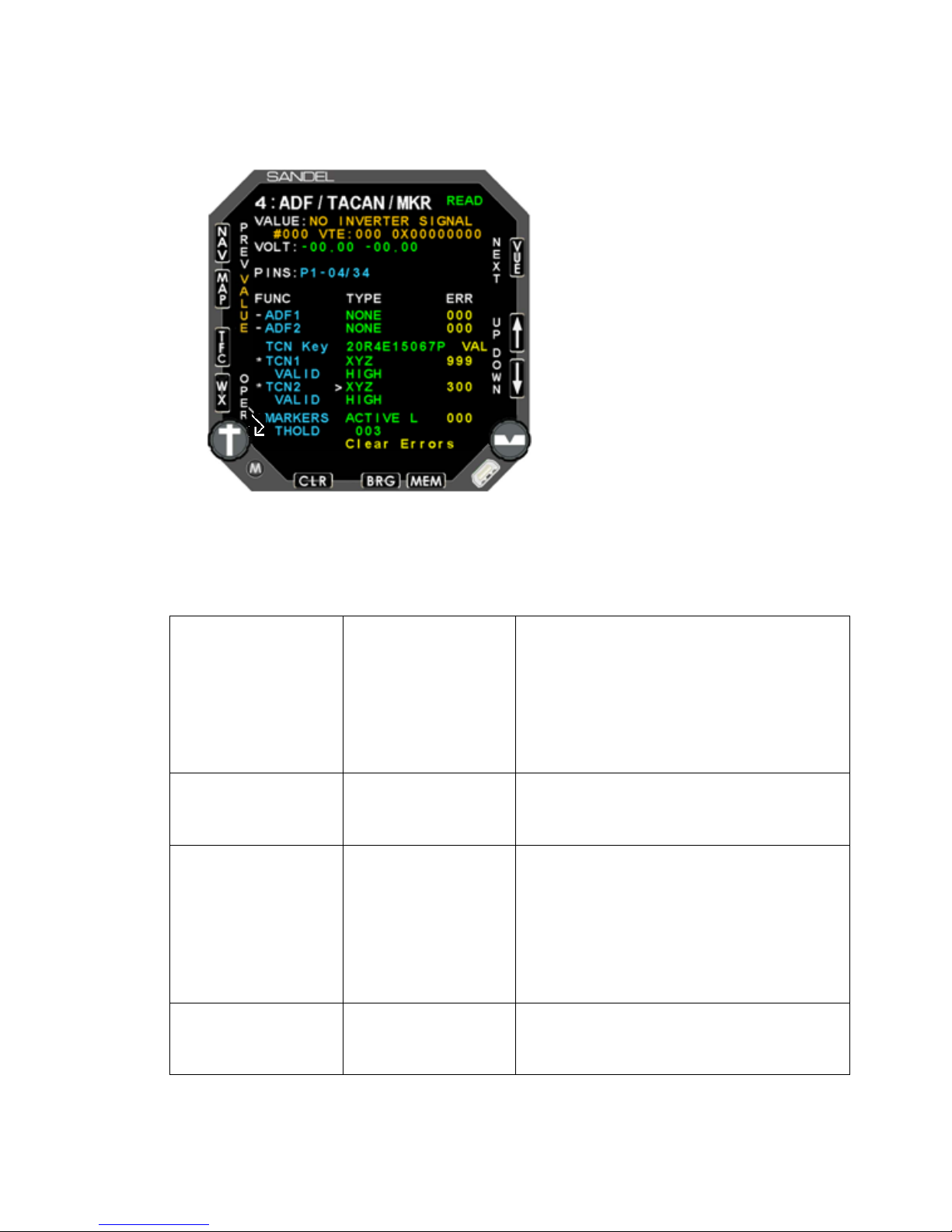
ADF1
NONE
S/C DC-
Selects type of ADF signal input. If
VALID
NONE
HIGH
Not shown if 42 9 or 4 29 H i s s elected for
ADF2
NONE
S/C DC-
Selects type of ADF signal input. If
VALID
NONE
HIGH
Not shown if 42 9 or 4 29 H i s s elected for
7.1.4 Page 4: ADF/TACAN/ MKR
Appendix A: Post-Ins talla tion Proc edures
The ADF page allows the selection for ADF1, ADF2, TACAN 1, TACAN 2, and
Marker sources.
Configuration Fiel d Options Comment
429
429H
bearing indica ti on i s off by 180°, change
selection to opposit e polarity.
XYZ
XYZS/C DC
LOW
429
429H
ADF source.
bearing indica ti on i s off by 180°, change
selection to opposit e polar ity.
XYZ
XYZS/C DC
82005-IM-R Sandel SN3500 Installation Manual Page 7-7
LOW
ADF source
Page 59

Appendix A: Post-Ins talla tion Proc edures
TCN Key
Blank by defa ult
Enter the purchased 11 character key
code to enable TACAN. Use the BRG
and MEM keys to select the character
and the MAP and TFC keys to move
the cursor.
TCN1
NONE
419
Selects type of TACAN signal input. If
VALID
NONE
HIGH
Not shown unless XYZ or XYZ- is
selected for TACAN s ource.
TCN2
NONE
Selects type of TACAN signal input. If
VALID
NONE
HIGH
Not shown unless XYZ or XYZ- is
selected for TACAN s ource.
MARKERS
NONE
429H
Selects type of input from the marker
THOLD
Default 003
Used to adjust the signal voltage
threshold when ACTIVE L or ACTIVE H
is selected for th e mark er beaco n i nput .
429
429H
429-MC
429H-MC
XYZ
XYZ-
429
429H
429-MC
429H-MC
XYZ
XYZ419
bearing indica ti on i s off by 180°, change
selection to opposit e polar ity.
bearing indica ti on i s off by 180°, change
selection to opposit e polar ity.
82005-IM-R Sandel SN3500 Installation Manual Page 7-8
ACTIVE L
ACTIVE H
429
beacon receiver.
Page 60
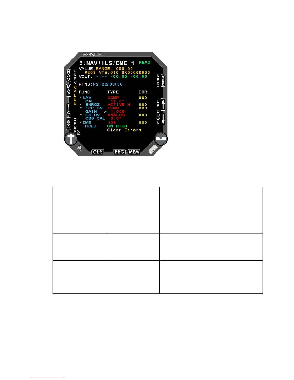
NAV
NONE
NO BRG
Selects NAV sig nal i np ut.
For 429 interfaces, the standard setting
is ‘TO’. Change to ‘FR’ if the received
CAL
Default 17.0°
Only used when COMP is selected for
the NAV signal input. A VOR test set
should be used to accurately calibrate
the displayed b eari ng poi nter rea ding.
ENRGZ
NONE
ACTIVE L
Selects ILS En erg iz e input .
7.1.5 Page 5: NAV/ILS/D ME 1
Appendix A: Post-Ins talla tion Proc edures
The NAV/ILS/D ME1 pag e allow s t he sel ect ion o f the N AV1 a nd D ME1 sourc es.
Configuration Fiel d Options Comment
429 TO
429H TO
429 FR
429H FR
bearing information is ‘from’ the VOR
station.
COMP
429
429H
ACTIVE H
82005-IM-R Sandel SN3500 Installation Manual Page 7-9
Page 61

Appendix A: Post-Ins talla tion Proc edures
LOC DV
NONE
Selects localizer signal input. The
in NAV converter to
decode localizer validity and deviation
If COMP is selected see following
“Composite LOC Calibration
procedure”.
GAIN
Used to calibra te LOC DV CO MP
GS DV
NONE
ANALOG
Selects glidesl ope sig nal inpu t.
OBS CAL
DEFAULT 0.0°
Calibrates NAV1 OBS .
DME
NONE
ANALOG
Selects DME signal input.
HOLD
NONE
ON LOW
Selects DME HOLD discrete input to
ZERO
DEFAULT 000
Present only if Analog DME is selected.
Use to set zero point of DME input if
necessary.
SCALE
DEFAULT 1.00
Present only if Analog DME is selected.
Use to calibrat e DM E i f nec ess ary .
429
429H
ANALOG
COMP
429
429H
429
429-MC
568
KSD
ON HIGH
SN3500 has a built-
from a composi te si gnal i nput.
active high or low .
7.1.5.1 OBS Calib ration ( Does not apply to 429 or 400HZ Differential Resolvers)
Note: Maintenance mode and operational mode can be toggled by pressing and
holding the CR S kno b.
a) In operational mode set the SN3500 course pointer (OBS) to zero degrees. Set
the NAV test set to z ero deg rees .
b) In Maintena nce Mod e, adj ust the OB S CA L set ting to cent er t he d evi ation needl e.
c) Set the test set to 45 degrees. Turn the course pointer to re-center the deviation
needle. If it is with a few degrees of 45 degrees, then proceed. Otherwise if it is
about 90 degrees out, change the OBS ROT setting on Maintenance Page 10 to
REVERSED and r etur n to s tep a.
82005-IM-R Sandel SN3500 Installation Manual Page 7-10
d) Check the to/from flag on the SN3500 display. If to/from is reversed (and correct
wiring has been verified) adjust the OBS CAL 180 degrees from the current
setting.
Page 62

e) Check the c our se poi nt er at 30 d eg ree i ncre ment s an d v erify cali br atio n.
7.1.5.2 Composite LOC Calibration Procedure
The following proce dur e ap pli es to SN3500 installations that h ave b een
configured to use th e SN3500 internal localizer converter.
LOC DV COMP
This procedure does not apply for any other LO C DV setting such as
Arinc 429 or Analog fro m an external LOC conv erter.
Ramp or Bench Test:
Perform the follow i ng proc edur e usi ng t he resp ectiv e air cra ft r ecei ver . This te st may
be perform ed w ith a ra mp tes t s et, or may b e per for med o n the benc h w ith a si gnal
generator at n ominal R F s ig nal lev el ( 25uV or gr eater) .
Appendix A: Post-Ins talla tion Proc edures
1. On the SN3500 NAV mai ntena nce pag e, s elect LOC D V a nd
change to COMP to selec t Composit e Local izer .
2. Select GAIN.
3. Set 0 DDM (STD) on the test set, and tune the r eceiv er to match
the LOC freq uenc y on t he test se t.
4. Adjust the SN4500 GAI N v al ue so th e aver age v alue o f LOC
AMPL reads 100 .0 +/- 2.5.
5. Exit the SN3500 maintenance pag e to the norm al pilot’ s LOC
display.
6. On the test set remov e bot h 90H z an d 1 50Hz simult an eousl y and
verify the SN3500 display flags within 2 sec ond s.
7. On the test set select .1 55 DDM Le ft a nd v eri fy tha t re movi ng
either tone individually will flag the SN3500 display w ithin 5
seconds.
8. On the test set select .155 DD M Ri ght an d ver ify that r em ovi ng
either tone individually will flag the SN3500 display w ithin 5
seconds.
Perform any other LOC per forma nce tests desir ed.
82005-IM-R Sandel SN3500 Installation Manual Page 7-11
Page 63
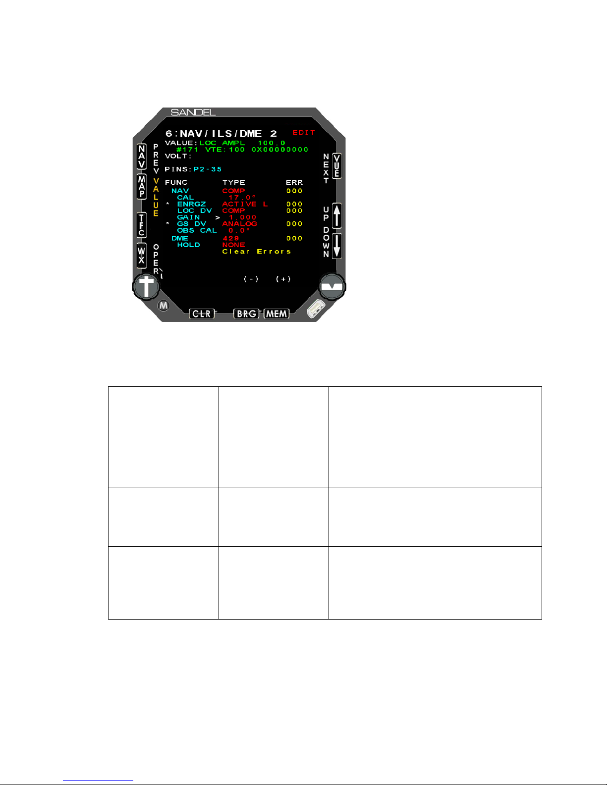
NAV
NONE
NO BRG
Selects NAV sig nal i np ut.
For 429 interfaces, the standard setting
bearing information is ‘from’ the VOR
CAL
Default 17.0°
Only used when COMP is selected for
the NAV signal input. A VOR test set
should be used to accurately calibrate
the displayed b eari ng poi nter rea ding.
ENRGZ
NONE
ACTIVE L
Selects ILS En erg iz e input .
7.1.6 Page 6: NAV/ILS/D ME 2
Appendix A: Post-Ins talla tion Proc edures
The NAV/ILS/D ME2 pag e allow s t he sel ect ion o f the N AV2 a nd D ME2 sourc es.
Configuration Fiel d Options Comment
429 FR
429H FR
is ‘TO’. Change to ‘FR’ if the received
429 TO
429H TO
station.
COMP
429
429H
ACTIVE H
82005-IM-R Sandel SN3500 Installation Manual Page 7-12
Page 64

Appendix A: Post-Ins talla tion Proc edures
LOC DV
NONE
Selects localizer signal input. The
decode localizer validity and deviation
If COMP is selected see “Composite
in the
previous sect ion.
GAIN
Used to calibra te LOC DV CO MP
GS DV
NONE
ANALOG
Selects glidesl ope sig nal inpu t.
OBS CAL
DEFAULT 0.0°
Calibrates NAV2 OBS. See OBS
calibration instructions for NAV1 in
section 7.1.5. 1.
DME
NONE
HI FR DME1
Selects DME signal input.
For installations with a single DME
receiver used by NAV1 and NAV2,
select LO FR DME1 (if low on DME2
40 indicates NAV2 selection)
or HI FR DME1 (if high on DME2 Hold
P1-40 indic ates NAV 2 s elect ion) .
HOLD
NONE
Selects DME HOLD discrete input to
active high or low. Not shown if above
DME selection is LO FR DME1 or HI
FR DME1.
429
429H
ANALOG
COMP
429
429H
429
429-MC
568
KSD
LO FR DME1
SN3500 has a built-in NAV converter to
from a composi te si gnal i nput.
LOC Calibration procedure”
Hold P1-
82005-IM-R Sandel SN3500 Installation Manual Page 7-13
ON HIGH
ON LOW
Page 65
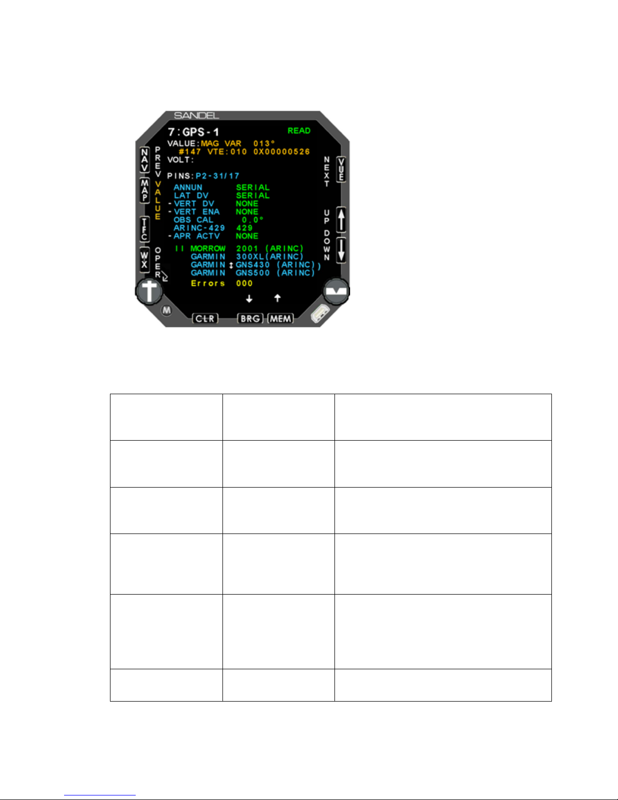
ANNUN
NONE
SERIAL
Automatically configured when GPS is
LAT DV
NONE
SERIAL
Automatically configured when GPS is
VERT DV
NONE
SERIAL
Automatically configured when GPS is
VERT ENA
NONE
SERIAL
Automatically configured when GPS is
OBS CAL
DEFAULT 0.0°
Automatically configured when GPS is
selected from list below. May require
232 interface and has a resolver
connected.
ARINC - 429
429
429H
Not shown when selected GPS does
not have ARINC 429 outpu t.
7.1.7 Page 7: GPS1
Appendix A: Post-Ins talla tion Proc edures
The GPS1 page allow s t he sel ect ion a nd con figur atio n o f the GPS1 i np ut.
Configuration Fiel d Options Comment
ACTIVE L
ANALOG
ANALOG
ACTIVE H
selected from list bel ow.
selected from list bel ow.
selected from list bel ow.
selected from list bel ow.
ACTIVE L
82005-IM-R Sandel SN3500 Installation Manual Page 7-14
adjustment if the GPS receiver uses an
RS-
Page 66

Appendix A: Post-Ins talla tion Proc edures
APR ACTV
NONE
ACTIVE H
GPS approach active source select.
GPS
Select from list
Select the appropriate model of GPS
from the list. Press the SET soft key
(CLR button) t o pr ogr am.
ANNUN IN
ACTIVE L
82005-IM-R Sandel SN3500 Installation Manual Page 7-15
Page 67
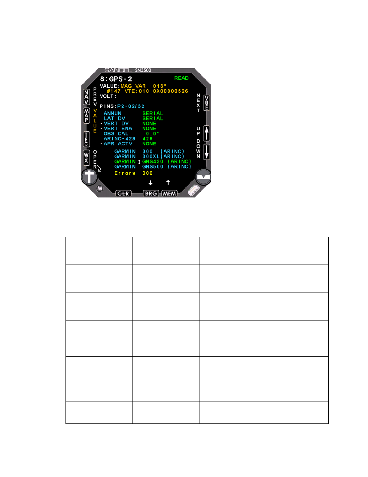
ANNUN
NONE
SERIAL
Automatically configured when GPS is
LAT DV
NONE
SERIAL
Automatically configured when GPS is
VERT DV
NONE
SERIAL
Automatically configured when GPS is
VERT ENA
NONE
SERIAL
Automatically configured when GPS is
OBS CAL
DEFAULT 0.0°
Automatically configured when GPS is
selected from list below. May require
adjustment if the GPS receiver uses an
232 interface and has a resolver
connected.
ARINC – 429
429
Not shown when selected GPS does
7.1.8 Page 8: GPS2
Appendix A: Post-Ins talla tion Proc edures
The GPS2 page allow s t he sel ect ion a nd con figur atio n o f the GPS2 i np ut.
Configuration Fiel d Options Comment
ACTIVE L
ANALOG
ANALOG
ACTIVE H
selected from list bel ow.
selected from list bel ow.
selected from list bel ow.
selected from list bel ow.
ACTIVE L
82005-IM-R Sandel SN3500 Installation Manual Page 7-16
429H
RS-
not have ARINC 429 outpu t.
Page 68

Appendix A: Post-Ins talla tion Proc edures
APR ACTV
NONE
ACTIVE H
GPS approach activ e source select.
GPS
Select from list
Select the appropriate model of GPS
oft key
(CLR button) t o pr ogr am.
ANNUN IN
ACTIVE L
from the list. Press the SET s
82005-IM-R Sandel SN3500 Installation Manual Page 7-17
Page 69
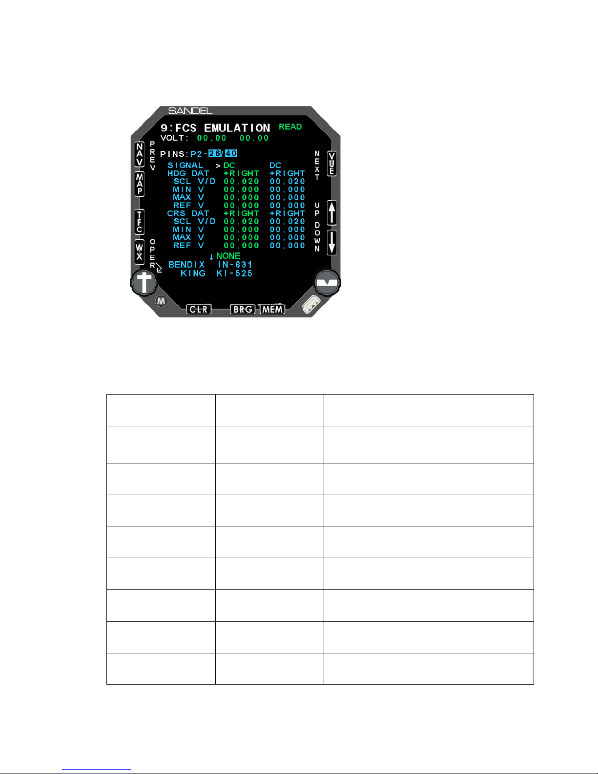
SIGNAL
DC
AC
Automatically configured when FCS is
selected from list bel ow.
HDG DAT
+RIGHT
Automatically configured when FCS is
SCL V/D
Default settings reset when FCS is
selected from list bel ow.
MIN V
Default settings reset when FCS is
selected from list bel ow.
MAX V
Default settings reset when FCS is
selected from list bel ow.
REF V
Default settings reset when FCS is
selected from list bel ow.
CRS DAT
+RIGHT
+LEFT
Automatically configured when FCS is
selected from list bel ow.
SCL V/D
Default settings reset when FCS is
selected fr om list bel ow.
MIN V
Default settings reset when FCS is
selected from list bel ow.
7.1.9 Page 9: FCS EMULATI ON
Appendix A: Post-Ins talla tion Proc edures
The FCS Emulati on allo w s the sel ec tio n and con figur atio n o f the FCS i nter fac e.
Configuration Fiel d Options Comment
+LEFT
selected from list bel ow.
82005-IM-R Sandel SN3500 Installation Manual Page 7-18
Page 70

Appendix A: Post-Ins talla tion Proc edures
MAX V
Default settings reset when FCS is
selected from list bel ow.
REF V
Default settings reset when FCS is
selected from list bel ow.
FCS
Select from list
Select the appropriate emulation from
the list. Press the SET soft key (CLR
button) to prog ra m.
HDG V/D and CRS V/D increase or decrease the gain of the course or heading error
relative to th e lubber line, and normally match the volts/degree i n put of the associated
autopilot computer. These values default when the FCS selection is initially set, but
can be adjust ed in-flight if necessary , in VF R c ondi tio ns, as fol low s:
a) Engage the autopilot in HDG mode. After the aircraft is established on the
desired heading, move the heading bug knob a large amount and ensure that the
aircraft turns to the heading bug and rolls out normally without instability,
overshooting or undershooting to the desired heading. To correct for
overshooting or instability, reduce the HDG V/D setting. To correct for
undershooting , incr eas e th e HDG V/D sett ing.
b) Engage the au topi lot i n NAV mode an d tur n o ff the NA V rec eiv er to pr o vi de a z ero
course error. Repeat the tests and adjustments above using the course pointer
and adjust the C RS V/D setti ng as ap propr i ate.
c) Use the REF V adjustment to center the heading and course rollout if not
precisely on th e l ubber l ine. This w i ll r arely be r eq uired.
HDG DAT and CRS DAT allow the direction sensing to be reversed during
installation. Changing these settings is identical to reversing H/C on a synchro
control trans form er.
The other settings on this page are not for installer adjustment except on advice of
the factory, s erv ice b ull etin, or s erv ic e infor mati on l ett er.
Note that the adjustments are shown in the left column of values. T he right column
shows the default values for reference purposes.
82005-IM-R Sandel SN3500 Installation Manual Page 7-19
Page 71
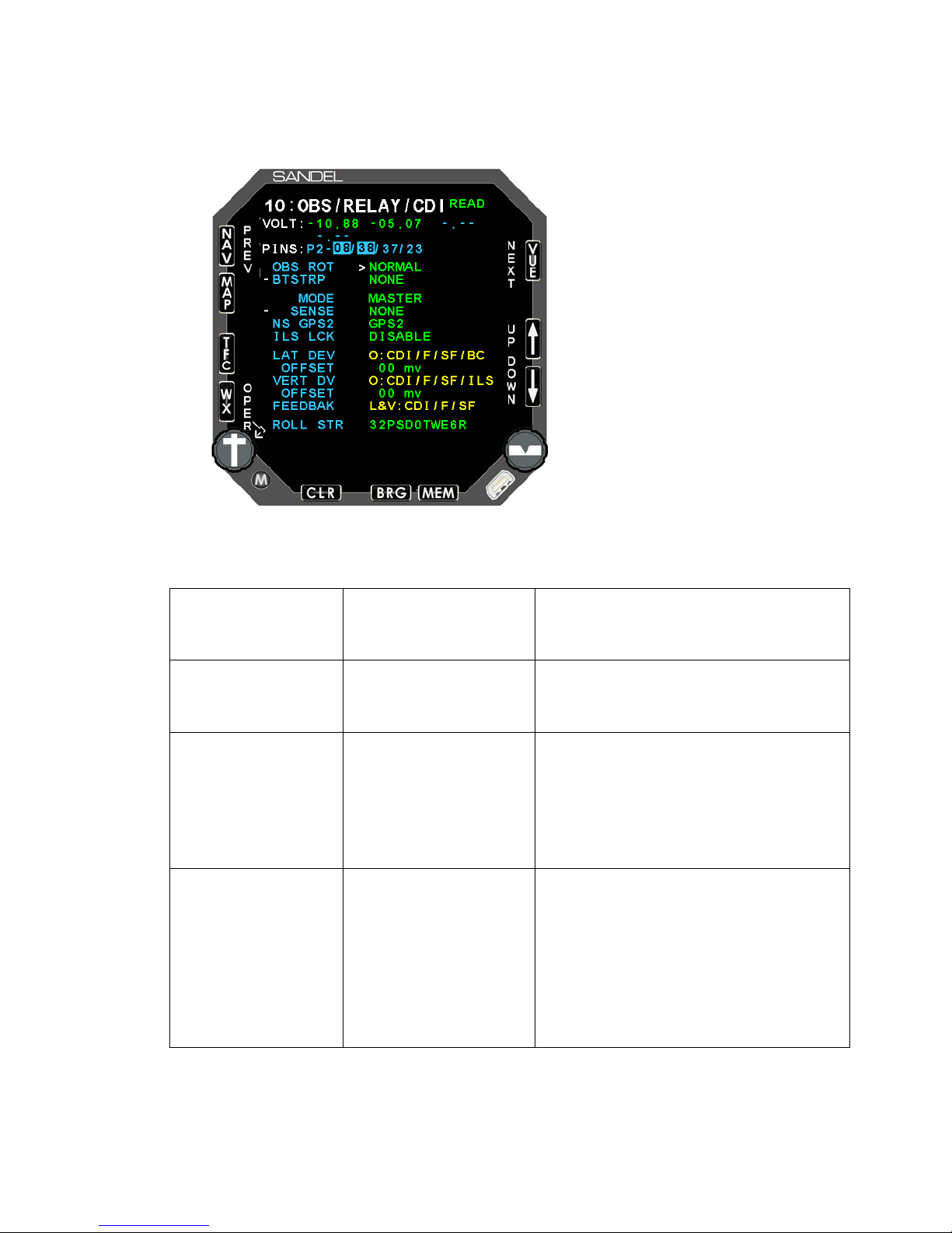
OBS ROT
NORMAL
DIFF A
Adjusts rotation o f OBS.
when interfaced to
400HZ differe ntial r es olv er .
BTSTRP
NONE
REVERSE
Enables bootstrap synchro heading
MODE
MASTER
Selects NAV/GPS switching mode.
In MASTER mode, the SN3500’s
NAV button is used to switch
SLAVE mode a remote switch is
used.
SENSE
NONE
G1/G2/N2
Enables relay sense input to verify
relay switching. If a low is not
corresponding NAV source will be
lined on the pilot’s display when
7.1.10 Page 10: OBS / RELAY / C DI
Appendix A: Post-Ins talla tion Proc edures
Configuration Fiel d Options Comment
REVERSED
NORMAL
Select DIFF A
output.
SLAVE
between NAV and GPS sources. In
GPS1
GPS2
detected on the r elay sens e in put, th e
GPS1/GPS2
NAV2
GPS1/NAV2
red
selected.
GPS2/NAV2
82005-IM-R Sandel SN3500 Installation Manual Page 7-20
Page 72

Appendix A: Post-Ins talla tion Proc edures
NS GPS2
GPS2
Normal operation of sense lines as
When replacing a SN3308 with a
SN3500, use this selection and
Sense selections for
installations with dual Garmin GNS
Receivers where both receivers (All
four NAV sources) are made
available as NAV sources. This is the
5) for a relay which
08 install
install sheet #26.
ILS LCK
DISABLE
ENABLE
Enables/disables ILS Lockout feature
of the ILS input for NAV1/NAV2.
LAT DEV
n/a
Monitors FCS v oltag e o utp uts.
OFFSET
n/a
Adjusts zero o ffs et o f th e lat eral
deviation output. *
VERT DV
n/a
Monitors FCS v oltag e o utp uts.
OFFSET
n/a
Adjusts zero o ffs et o f th e ver tical
deviation outp ut. *
FEEDBAK
n/a
ROLL STR
Blank by defa ult
Enter the purchase d 11 character
(software ver sion
3.00 and abov e)
NAV2 & GPS2
described above in Se nse sel ections .
“NAV2” in
sense input (P3is wired to both the NAV-2 and GPS2 relay outputs. Ref: SN33
manual 90106-IM-G (4), dual Garmin
(Software ver sion
4.04 and later and
requires LED
backlight.)
• * This adjustm en t may be used to fine tune the autopilot localizer or gli de slope tracking if
the SN3500 lat and vertical dev i ation outp uts hav e bee n conn ect ed to th e auto pil ot.
key code to enable roll steering. Use
the BRG and MEM key s to sel ect t he
character and the MAP and TFC
keys to move t he cur s or.
82005-IM-R Sandel SN3500 Installation Manual Page 7-21
Page 73
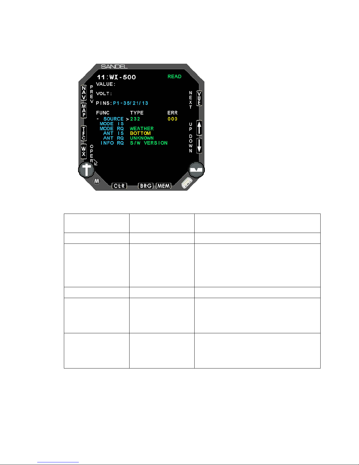
SOURCE
NONE
232
Set to 232 to enable WX-500 interface.
MODE IS
n/a
Displays curr ent m ode of t he WX-500.
MODE RQ
WEATHER
SELF TEST
Selects mode of WX-500. Select
ANT IS
n/a
Displays curr ent a nte nna co nfig urati on.
ANT RQ
TOP
Software selection of antenna location.
Normally not used as the antenna
500.
INFO RQ
FAULT LIST
S/W VERSION
Requests information from WX-500.
Information will be shown at the bottom
7.1.11 Page 11: WX-500
Appendix A: Post-Ins talla tion Proc edures
Configuration Fiel d Options Comment
STRIKE TEST
WEATHER for n ormal oper ati on.
DEMO
NOISE MONITOR
BOTTOM
UNKNOWN
location is set by jumpers on the WX-
CONFIGURATION
ENVIRONMENT
of the display .
82005-IM-R Sandel SN3500 Installation Manual Page 7-22
Page 74
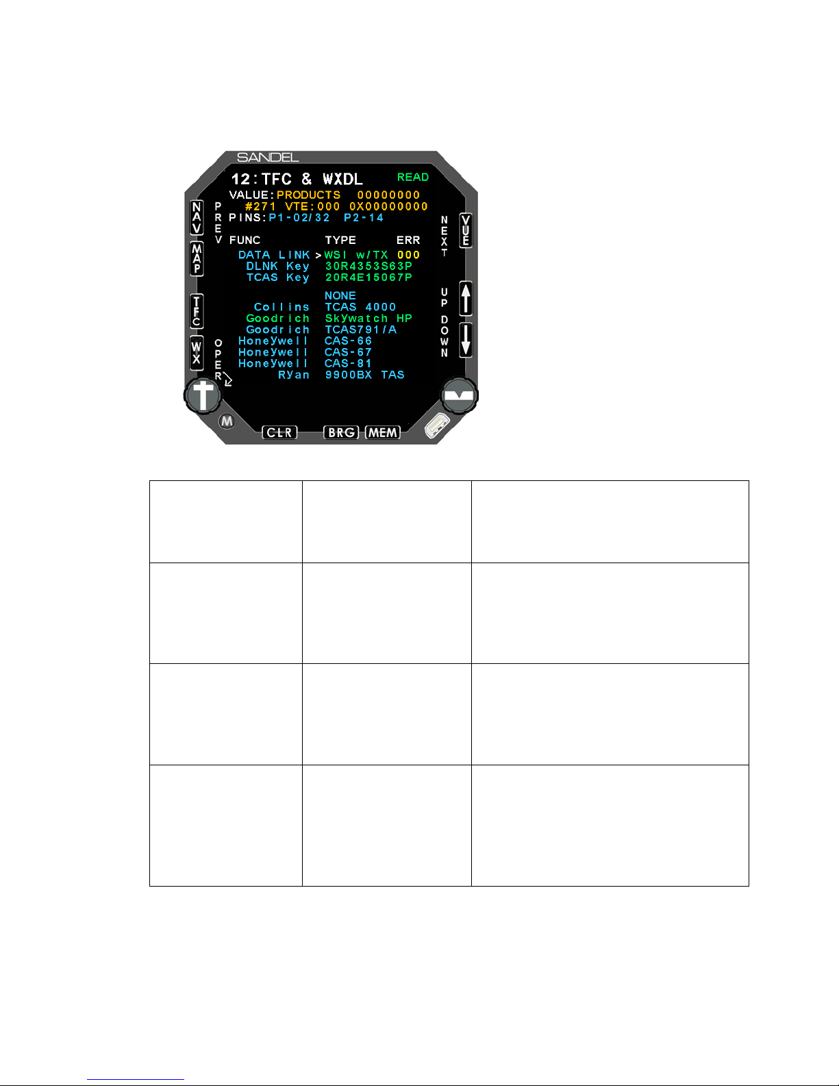
DATA LINK
WSI w / TX
SN3500 is sol e dis play .
SN3500 is wired as receive only,
another display is connected to the
WSI receiver.
DLINK KEY
Blank by defa ult
Enter the purchased 11 character
ey code to enable data link weather.
Use the BRG and MEM keys to
select the character and the MAP
and TFC keys t o mov e t he cur sor.
TCAS KEY
Blank by defa ult
Enter the purchased 11 character
key code to enable traffic. Use the
t the
character and the MAP and TFC
keys to move t he cur s or.
TCAS Model
Collins TCAS 4000
Ryan 9900BX TAS
Select the appropriate model of
66.
7.1.12 Page 12: Traffic
Appendix A: Post-Ins talla tion Proc edures
Configuration Fiel d Options Comment
(Software version
3.00 and abov e)
(Software ver sion
WSI no TX
k
3.00 and abov e)
BRG and MEM keys to selec
Goodrich Skywatch HP
Goodrich TCAS791/A
Honeywell CAS-66
Honeywell CAS-67
Honeywell CAS-81
TCAS from the list. Press the SET
soft key (CLR b utt on) t o pr ogr am.
NOTE: Users of Honeywell KTA-810
systems should configure as CAS-
82005-IM-R Sandel SN3500 Installation Manual Page 7-23
Page 75
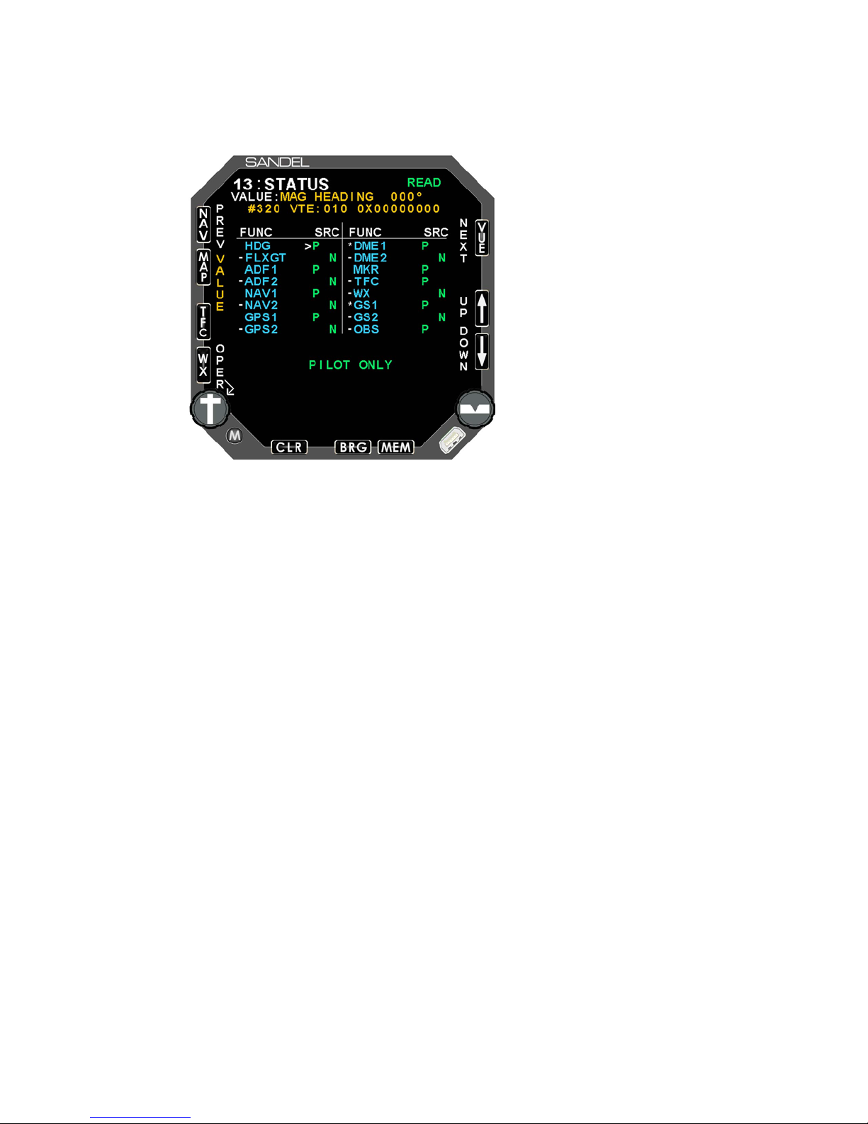
7.1.13 Page 13: STATUS
Appendix A: Post-Ins talla tion Proc edures
Sens or s um mary stat us.
82005-IM-R Sandel SN3500 Installation Manual Page 7-24
Page 76
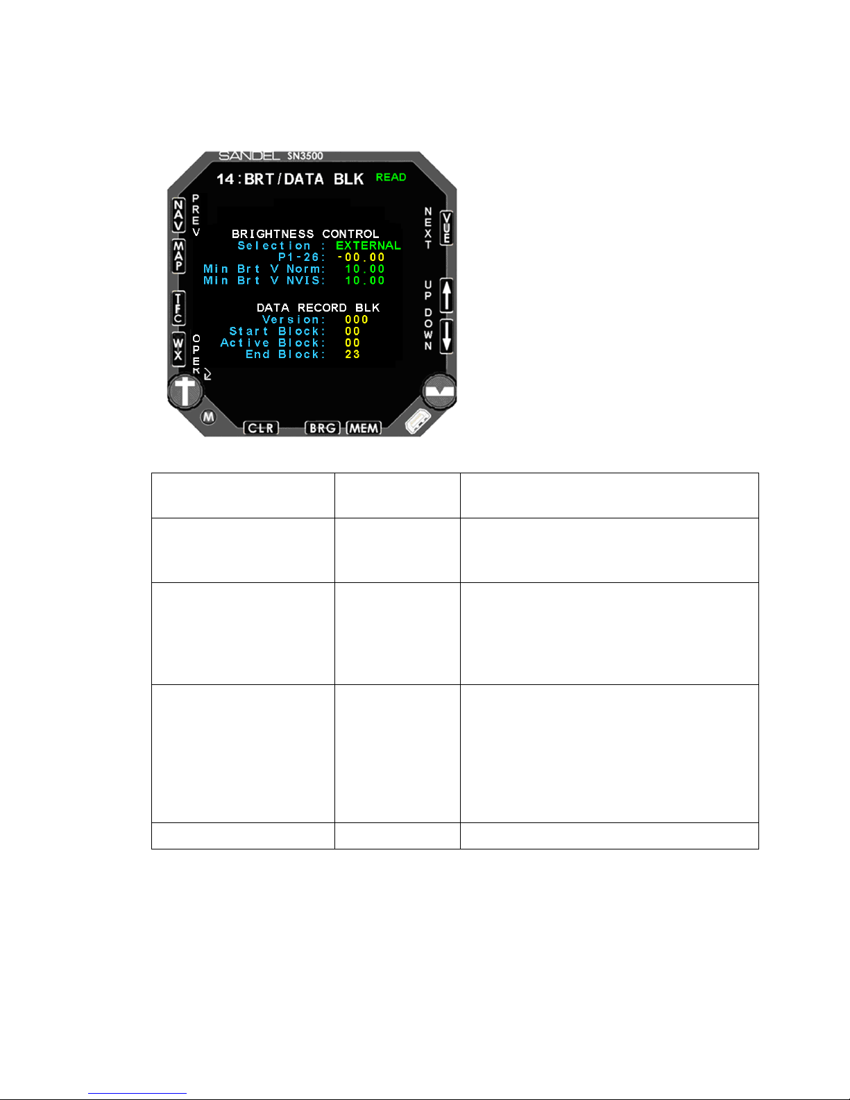
Selection
INTERNAL
EXTERNAL
Selects the brightness control to be
external or intern al.
P1-26
NONE
Monitors external brightness bus
voltage. Not shown when brightness
control selecti on i s s et t o IN TERNA L.
Min Brt V Norm
Adjusts the external brightness bus to
Adjustable from 1.5 volts to 15.0 volts.
Not shown when brightness control
selection is s et to IN TER NAL.
Min Brt V NVIS
Adjusts the external brightness bus to
lts to 15.0 volts.
Not shown when brightness control
DATA RECORD BLK
None
For factory use.
7.1.14 Page 14: BRT/DATA BLK
Appendix A: Post-Ins talla tion Proc edures
Configuration Fiel d Options Comment
Calibrating the external brightness control minimum brightness:
BEFORE performing calibration:
Select the “BRT” m aintenance page, select EXTERNAL for brightness control.
82005-IM-R Sandel SN3500 Installation Manual Page 7-25
the desired night-brightness voltage.
the desired NVIS brightness voltage.
Adjustable from 1.5 vo
selection is set to INTERNAL. Not
applicable to n on-NVIS units.
Page 77
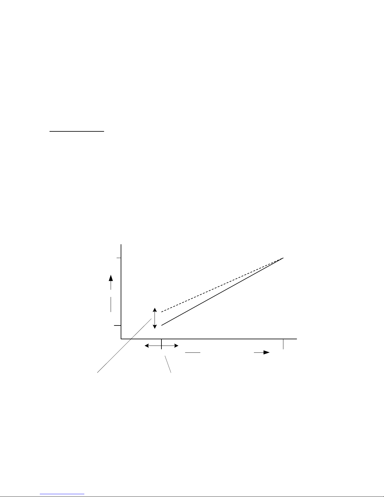
Appendix A: Post-Ins talla tion Proc edures
Vzero
Vmax
(aircraft
pwr –
4v)
Brightness
Extern Brt Bus Volts
100%
0
Pilot
Brightness
Trim
Maintenance
Page
Adjustment
To calibrate minim um brightness, set aircraft to NVIS OFF and do the following from
BRT maintenance page. Please note: The maintenance page always displays at 100%
brightness. You need to exit MAINT by pressing and holding the left knob to see the
resulting brightness adjustment.
1. Select “Min Brt V Norm” with up/down arrow keys
2. Set the aircraft external brightness bus at the desired night-brightness voltage. This
voltage will be displayed on-screen.
3. Press “SET” softkey. This will set Vzero (see graph below) at the current bus voltage
minus 2.00 volts
4. Exit MAINT by pressing and holding the left knob and check the brightness balance
with the rest of the cockpit. If you need further adjustment, re-enter BRT maintenanc e
page by pressing and holding the left knob and trim the “Min Brt V Norm” setting using
“+/- softkeys. A lower voltage setting number will INCREASE the brightness.
Repeat steps 1,2,3,4 with external NVIS selected
NOTE: From this point on the pilot will be able to trim the minimum brightness, if
desired, using the ‘M’ button to enter the pilot’s menu.
82005-IM-R Sandel SN3500 Installation Manual Page 7-26
Page 78
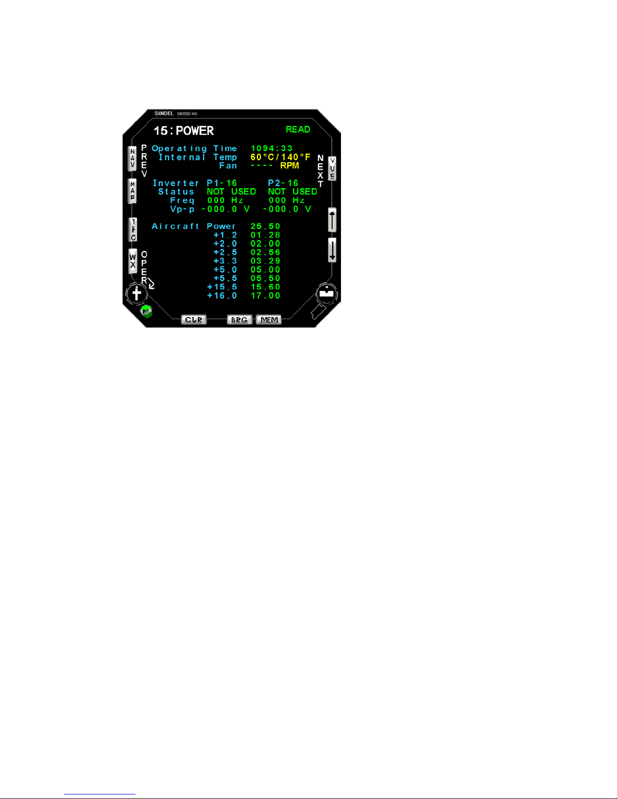
7.1.15 Page 15: Power
Appendix A: Post-Ins talla tion Proc edures
Monitors power input s to the SN3500 including the #1 and #2 i nv erters .
82005-IM-R Sandel SN3500 Installation Manual Page 7-27
Page 79
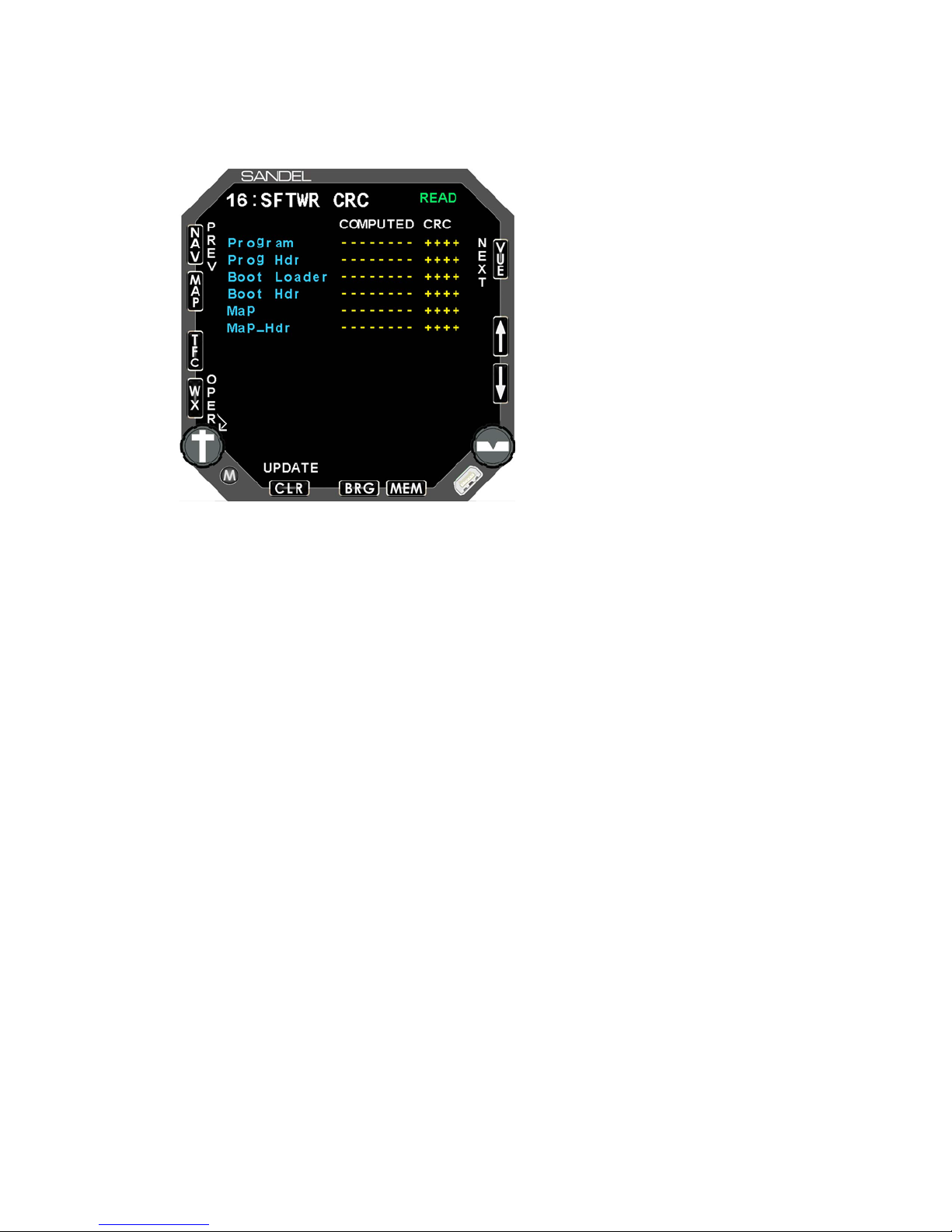
7.1.16 Page 16: Software CRC
Appendix A: Post-Ins talla tion Proc edures
Displays CRC val ues for the sof tw are a nd da tabas e prog ra ms. Pr ess t he [U PDA TE]
soft key to re-calcul ate . C ontac t Sa ndel i f FAI L i s annu nciat ed for any of th e v alue s.
82005-IM-R Sandel SN3500 Installation Manual Page 7-28
Page 80
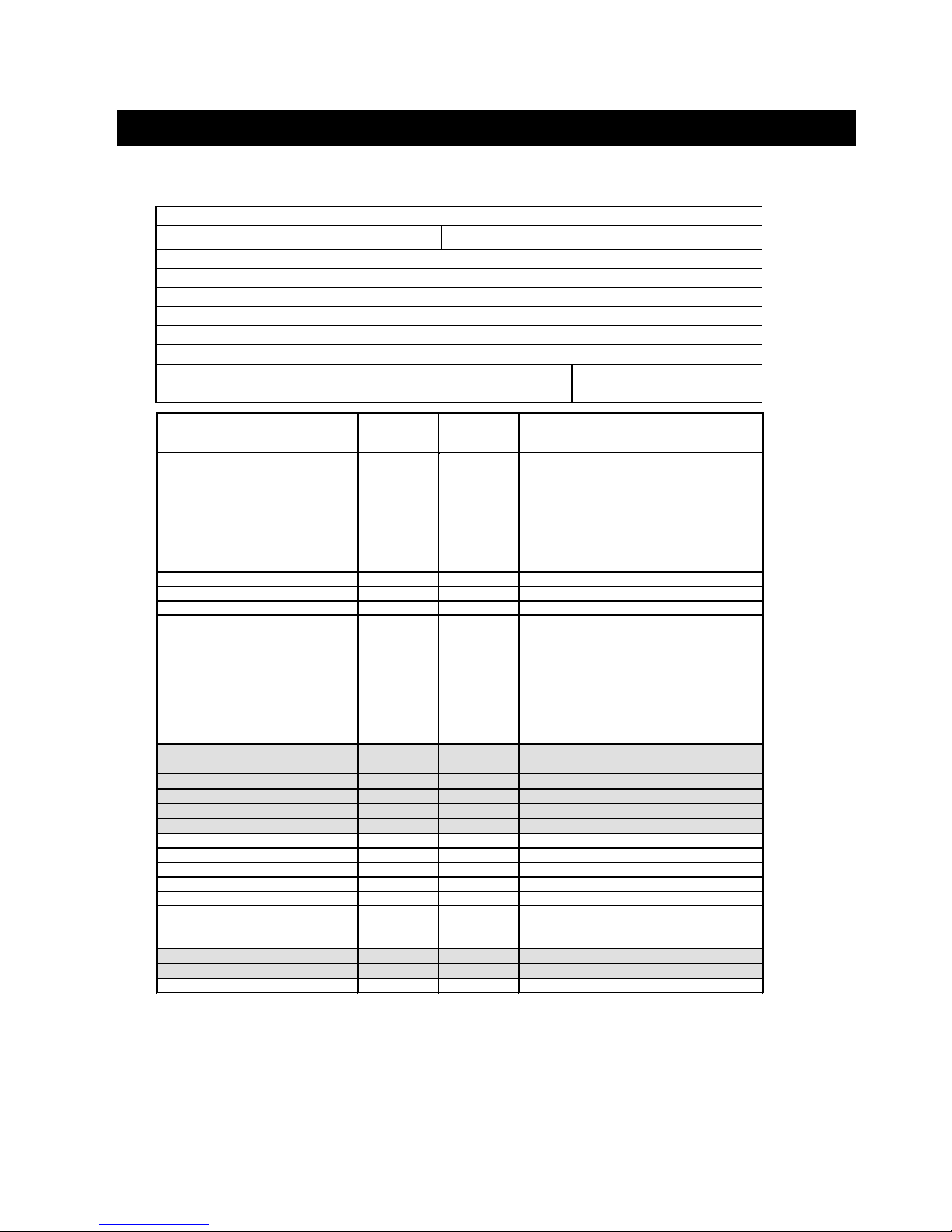
Appendix B: Environmenta l Qualifi cation For m
NAMEPLATE NOMENCLATURE: [(A2)(F1)]ZBAB[(H)(R)]XXXXXXZBABB[WW]M[XXF2]XXA
TYPE/MODEL NO: SN3500
TSO NUMBERS: C113
MANUFACTURER’S SPECIFI C ATION AND/OR OTHER APPLICABLE SPECIFICATION:
a.) Design Requirements & Objectives For SN3500 EHSI, document number 82006-0010
b.) RTCA D0-160D Environmental Plan For Sandel SN3500 EHSIdocument nu mber 82006-0090
MANUFACTURER: Sandel Avionics, Inc.
ADDRESS: 2401 Dogwood Way
Vista, CA 92083
REVISION & CHANGE NOS. OF D0-160: Revision D, Change
Nos. 1 & 2
DATE TESTED:
From: 06/04
ENVIRONMENTAL
TESTS
RTCA/DO-
160D
SECTION
Equipment
Test
Category
Notes
Temperature & Alt itud e
Temperature Variation (combined):
Low Temperature
-Ground Survival
-Operational
High Temperature
-Ground Survival
-Operational
Altitude
-Decompression
-Overpressure
4.0
5.0
4.5.1
4.5.2 & 4.5.3
4.6
4.6.2
4.6.3
[(A2)(F1)B]
PASS
In
-Flight Loss of Cooling
4.5.4 [(A2)Z]
PASS
Humidity
6.0
A
PASS
Operational Shock and Crash Safety
7.0
B
PASS
Vibration 8.0
[(H)(R)]
PASS:
RESONANT FREQUENCIES:
Section 8.7.2, Step a. and d.:
Pre-Scan: X: 195Hz, Y: 500Hz, Z: 160Hz
Post-Scan: X: 195Hz, Y: 450Hz, Z: 150Hz
Section 8.8.1.3, Steps a. and e.:
Pre-Scan: X: 190Hz, Y: 425Hz, Z: 145Hz
Post-Scan: X: 190Hz, Y: 625Hz, Z: 145Hz
Section 8.8.1.3, Steps b. and d.:
Pre-Scan: X: 190Hz, Y: 390Hz, Z: 150Hz
Post-Scan: X: 190Hz, Y: 625Hz, Z: 150Hz
Explosion
9.0
X
Water-proofness
10.0
X
Fluids Susceptibility
11.0
X
Sand and Dust
12.0
X
Fungus
13.0
X
Salt Spray
14.0
X
Magnetic Effect
15.0
Z
PASS
Power Input
16.0
B
PASS
Voltage Spike
17.0
A
PASS
Audio Frequency Susceptibility
18.0
B
PASS
Induced Signal Susceptibility
19.0
B
PASS
Radio Frequency Susceptibility
20.0
[WW]
PASS
Radio Frequency Emission
21.0
M
PASS
Lightning Induced Transient Susceptibility
22.0
[XX(EF)2]
PASS
Lightning Direct Effects
23.0
X
Icing
24.0
X
Electrostatic Discharge
25.0
A
PASS
8 Appendix B: Environmental Qualificat ion Form
RTCA/D0-160D Environmental Qualification Form (Lamp Models)
82005-IM-R Sandel SN3500 Installation Manual Page 8-1
Page 81
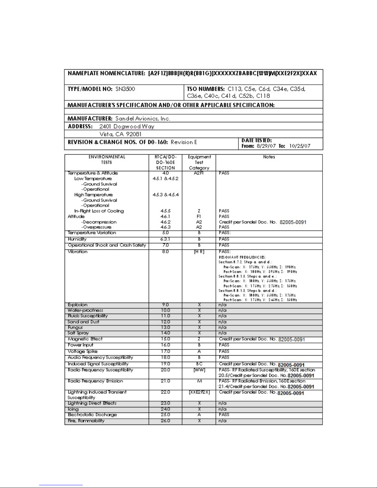
Appendix B: Environmenta l Qualifi cation For m
RTCA/DO-160E Environmental Qual ificati on Form (LED Models)
82005-IM-R Sandel SN3500 Installation Manual Page 8-2
Page 82

Appendix C: Sample FAA Form 337
9 Appendix C: Sample FAA Form 337
NOTICE
Weight and balance or oper atin g lim i tation ch anges sh all b e e nter ed in th e appr opr iat e
aircraft recor d. An al ter atio n m ust b e com pati bl e with all pr evio us al tera tions to ass ure
continued con form ity with t he appl icabl e airwor t hiness req uir em ents.
8. Description of Work Accomplished
(If m ore spa ce is r equir ed, attac h a dditi on al sh eets . Ide ntify with aircr af t nati onal ity
and registrati on m ark and date wor k com plet ed .)
A. Installed the follow ing equi pment and c ompo nents :
1. Sandel Avionics, Inc. , SN 3500 N avi gati on D ispl ay (or as appr opr ia te), Part
Number SN3500-000 (or as appropriate)
2. Sandel Avionics LLC, Cl amp Fixtur e 3ATI, Par t Number 610 62.
B. The Sandel Avionics S N350 0 is int erf aced t o the foll owi ng eq uip ment:
1. Garmin Internat ion al, G PS1 65, G PS N avi gati on Rec ei ver (Appr oved f or En
route, Ter minal, an d Non-precision Approach). ( or as appropri ate)
2. AlliedSignal El ec tronic s and Av i onics, KX 165 C om munica tion s a nd
Navigation Recei v er. (or as appropr iate)
3. AlliedSignal El ec tronic s and Av i onics, KX 155 C om munica tion s a nd
Navigation Receiver. (or as appropriate)
4. AlliedSignal Elec tronic s and Avi onics, KRA 10A Radar Al timet er Syste m. (or
as appropriat e)
5. AlliedSignal El ec tronic s and A vi onics, KR 22 M a rker Receiv er . (or as
appropriate)
6. AlliedSignal El ec tronic s and Av i onics, KG 102A Directional Gyro. (or as
appropriate)
7. AlliedSignal El ec tronic s and Av i onics, KM T 112 M agneti c Azi muth
Transmitter. (or as appropr iate)
(By example sta te the f oll owing fu ncti onal int erf ace proper ties ). ..
C. The SN3500 receives and proce sses GP S navi gati on i nfor mati on for di g ital an d
waypoint display from the GP S1 65. Thes e oper at ions ar e cons ider ed
supplemental nav igatio n.
82005-IM-R Sandel SN3500 Installation Manual Page 9-1
Page 83

Appendix C: Sample FAA Form 337
D. The SN3500 receives and proce sses VOR, locali zer, and gl ideslo pe devi ation and
composite audio for bear ing display from the KX 165. Th ese operat ions ar e
considered primar y means o f navig ation.
E. The SN3500 receives and pr ocesses gl idesl ope devi ation and com pos ite audio f or
bearing display fro m th e KX 15 5.
F. The SN3500 receives a nd proces ses mark er beaco n receiv er infor mation f or
illumination from the KR 22.
G. The SN3500 receives and pr ocesses magnetic headi ng for digi tal and g raphic
display from t he KG 10 2A and KM T 11 2.
H. Inter ference a nd fu nctio nal t ests a nd i nspec tio ns w er e acco mpli shed w i th
reference to Advisory C irc ular 2 3.131 1. ( or as a ppro priat e) .
I. A system design a nd an aly sis w as conduc ted w i th re fere nce to A dv isor y Cir cular
2X.1309-1( ). (or as a pp ropri ate) .
J. Federal Aviation Reg ul ati ons, 2X.1 30 1, 2X .1309 (a) , (b) and (d) , 23. 1311 ,
2X.1321(a), ( b) and (d), 2X.13 22, 2X . 1327( a), 2X.1 331, 2X 1351 , 2X .135 7(a) (d), 23.1365, 2X.13 81, 2X .1529, and 2X .1581 (or as appropri ate), w ere th e bas is
of compliance.
K. Installation appr oval is s oug ht w ith re fer ence t o Fl ig ht Stand ards In form atio n
Bulletin, FSAW 95-09( ) (Amen ded) , titl ed "El ect ronic Hori zont al Si tua tio n I ndica tor
(EHSI) Approv als" .
L. The aircraft equipment li st, a nd w ei ght an d bal ance w er e rev ised a nd re cor ded
within the airc ra ft mai nt enanc e r ecor ds.
M. All pertinent r ecor ds o f t his al ter ati on are on file at (S tat e your re pair s tat ion nam e
and number).
-------------------------------------------------------- End ------------------------------------------------
82005-IM-R Sandel SN3500 Installation Manual Page 9-2
Page 84

Appendix D: Sample Airpla ne Flight Manual Supple ment
10 Appendix D: Sample Ai rplane Flight Manual Suppl ement
The following is bei ng provided for installati ons i n w hich t he l ocal F SDO req uir es
an Airplane Fli ght Man ual Suppl e ment. This Sa mpl e is si mply bei ng pro vi ded for
the convenienc e o f the i nstall er. Not e th at t he c ov er pag e, ta ble of cont ents and
log of revisions h as n ot bee n in clud ed h ere, an d wi ll be s peci fic to y our
installation. The tex t is speci fic to the i nstal le d eq uipm ent, and al s o sp eci fies ILS
LOCKOUT operati on. This text must be m odified by the installa tion f acility to be
compatible w ith th e ins t alled equi pme nt.
SECTION I - GENERAL
The Sandel Avionics SN3500 Primary Navigation Display (PND) is a compact
three-inch instrument that performs the functions of a traditional Horizontal
Situation Indic at or c o m bi ne d with a two-pointer RMI. The SN 35 00 al s o di s plays a
moving map, Stormscope data, FIS-B data link weather, traffic information,
marker beacon a nd GPS annunciators if the air c raft is ap pr opr i a tel y equipped and
configured.
Add following shaded t ext if Dat a Lin k W eat her i s in stal led :
FIS-B Weather Data is intended for the purpose of assisting in long-range
strategic flight planning only. Please note that its delayed updating and lack of
sufficient resolution makes it unsuitable for tactical maneuvering of the aircraft. It
also differs significantly from on-board weather radar (which scans a narrow
vertical angle) since it portrays radar returns from multiple ground stations
extending from the surface up to the highest flight levels. For these reasons it
may not even dir ec tly refl ect t he cur rent fl ight co nditio ns.
SECTION II LIMITATIONS
The system mus t uti liz e so ftwar e v ersi on X .XX or l ater F AA appr ov ed ve rsi on.
The SN3500 Navigation Display Pilots Guide, SPN 82005-PG (or applicable
revision corresponding to the software version) must be immediately available to
the flight crew.
The “CRC Self Test Failed” message must not appear on power-up if flight
operations are predi cat ed on the use of th e SN3500 Primary Navigation Display.
Add following shaded t ext if Dat a Lin k W eat her i s in stal led:
The FIS-B weather display shall not be used for tactical maneuvering of the
aircraft.
SECTION III EMERGENCY PROCEDURES
If the SN3500 fails to op erate, use the magn etic com pass as a headi ng source .
82005-IM-R Sandel SN3500 Installation Manual Page 10-1
Page 85

Appendix D: Sample Airpla ne Flight Manual Supple ment
If the remote di recti onal g yro ( DG) becomes i no perati ve, the magnetic flux gate wi ll
provide the heading, and the resulting heading display will respond much more
slowly than normal. The compass rose changes color from white to amber, and
digital headi ng nu mbers w il l be redl in ed.
If the fluxgate fails, the SN3500 Navigation Display will continue to display
heading based on the directional gyro (DG) input. The compass rose changes
color from w hite t o am ber , hea ding num bers w ill be r edl ined .
Add following shaded text if FCS outputs are Used:
If the “FCS FDBCK ERR” message appears when in autopilot coupled NAV or
APPR mode, immediately monitor the lateral and vertical deviation indicators. If
they are not tracking properly, immediately disable the autopilot and flight director
NAV or APPR mode for the duration of the flight. HDG mode may still be used if
the autopilot track s th e SN35 00 HDG bug pro per ly .
Add following shaded text if FCS outputs are not used:
If the “FCS FDBCK ERR” message appears it has no effect on the autopilot
system and no pilot acti on needs to be taken.
SECTION IV NORMAL PROCEDURES
The SN3500 NAV push but ton selects the primary navigat ion s our ce N A V 1, N AV 2
or GPS1. The selected source will drive the SN3500 deviation indicator and the
autopilot.
ILS override will prevent selection of the GPS as long as an ILS frequency is
tuned on NAV1 or NAV2. This will be annunciated on the SN3500 Navigation
Display.
The SN3500 BRG pushbutton selects the bearing pointer 1 / 2 / both. The ‘M’
pushbutton followed by the BRG pushbutton selects the bearing pointer sources
NAV1, NAV2, GPS1, GPS2, or ADF .
Annunciation of all GPS modes is accomplished by messages on the GPS
receiver as w ell as on-screen annunciation o n the SN35 00 .
Add following shaded t ext if Traff ic is insta lled:
The traffic display mode is annunciated next to the TFC button. There are three
different modes available which control how the traffic targets are displayed.
Press the TFC b utt on r epea tedl y to cy cle t hroug h t he di fferen t mo des .
ON: Enables display of all targets within the selected map range (limited by
the maximum r ange of the i nstal led tra ffic s ys tem) .
M: Manual mode. Traffic will be displayed at the selected map range only
when alerting traffic is present, without auto ranging. Display range can be
changed manually .
82005-IM-R Sandel SN3500 Installation Manual Page 10-2
Page 86

Appendix D: Sample Airpla ne Flight Manual Supple ment
A: Auto mode. Traffic will be displayed at the selected map range only
when alerting traffic is present, except that the map range will auto-scale to an
appropriate r ange to s how the tr a ffic on-screen.
Manual (M) or Aut o (A ) mo des do n ot di spl ay non-alerting traffic.
Add following shaded text if Dat a Lin k We ath er is in st alled :
The SN3500 can display two types of weather information, precipitation and
lightning. Lightning may be displayed from two independent sources, WX-500
Stormscope or a FIS-B data link receiver. Both sources of lightning may be
displayed sim ulta neousl y .
The SN3500 WX push butt on s elec ts t he ty pe w eat her to be dis play ed:
PL: Precipi tati on & Lightni ng
P: Precipitati on only
L: Lightning only
The ‘M’ pushbutton followed by the WX pushbutton selects the lightning display
data source, either WX500, WSI, or both. The number to the right of the WX
annunciation displays the time in minutes since the last FIS-B precipitation data
was received from the d ata link r eceiver.
Weather graphics depicted on the SN3500 data link weather display may differ
significantly from the on-board weather radar or from out of the cockpit
observations for one or more of the fol lowi ng reason s.
− Vertical strata information is not provided by the FIS-B weather service.
The FIS-B weather data originates from NEXRAD ground based weather
radar observations that include weather measurements up to 30,000 feet
above the radar facility. The on-board weather radar is measuring returns
relative to th e cur rent fli g ht lev el.
− The FIS-B weather display is not exactly real time. Under certain
circumstances the time from when the NEXRAD radar observations were
made to when the data is displayed on the SN3500 can be as high as 40
minutes. During this time the position of the weather may have
significantly cha nged or moved relat iv e to t he air cra ft posi ti on.
− The graphic representation of precipitation is predicated on the level of
reflected ener g y from moisture in the air mass (the more moisture in t he ai r
mass, the higher level of energy returned to the radar antenna). This may
result in graphic presentation of precipitation on the SN3500 display when
no visible mois ture ca n be s ee n.
− Virga precipitation: the precipitation may be at a higher flight level and
evaporating be for e re achi ng th e c urr ent ai rcr aft flig ht l evel .
82005-IM-R Sandel SN3500 Installation Manual Page 10-3
Page 87

Appendix D: Sample Airpla ne Flight Manual Supple ment
Add following shaded text if LNAV/Roll Steering is install ed:
The LNAV (GPS roll steering) function is an extension of the of the SN3500
heading bug function. T o operate LNAV, the NAV source must be GPS and the
autopilot is k ept i n th e H DG m ode.
Press and hold the heading bug knob to select LNAV ARM. Leave the autopilot
in HDG mode.
Use the heading bug to turn the aircraft to a track that will intercept of the active
leg of the GPS flight plan. The dotted track line emanates from the airplane
present position on the map display, depicting the current track. Intercept will
occur where th e dot ted tr ack li ne c ross es t he G PS c ours e li ne.
During LNAV ARM the heading bug will remain color-filled and operational, until
leg capture occurs. When capture occurs the heading bug goes to outline form
and mode annunciation changes to LNAV in magenta. The steering commands
are then output on the HDG output of the SN3500, and the heading bug is
disconnected from the HD G output.
Press and hold the heading bug knob to exit from LNAV or LNAV ARM back to
HDG. The heading bug fill color will be restored and the heading bug will be
connected to the HDG output of the SN3500. The GPS Steering command is
disconnected.
The circuit breaker f or the SN3 50 0 Nav ig ation Di splay is located o n the l ow er rig ht
circuit breaker pa nel label ed EH SI 1 .
Refer to the SN3500 Primary Navigation Display Pilot’s Guide for other
procedures, error messages, alerts and more detailed FIS-B data link weather
information.
SECTION V PERFO RMA NCE DA TA
No Change to AF M.
82005-IM-R Sandel SN3500 Installation Manual Page 10-4
Page 88

Appendix E: Checkout Pr ocedures
11 Appendix E : Chec k out Procedures
11.1 Functional Groun d T est Procedures/R eport
The “Function al Gr oun d Tes t Pr oc edur es/Re por t” bel ow is for t he pur po se of
simplifying g round tes ts of the SN3 500. A co py of thi s re port (an d t he “ Opera tio nal
Flight Check Pr oc edur es/ R epor t”) must be retained by the instal ling ag ency an d
a copy must be install ed in t he airc ra ft mai nte nanc e rec ords . A copy must also be
forwarded to Sandel Avionics , Inc. along with the Warranty Reg is trati on For m,
Part Number 10 235, w h ich s houl d b e mail ed aft er op erati onal ac cepta n ce.
Repair Station Na me: _ _____ ____ _____ __ ___ _____ ____ _____ __ ___ _____ ___
Number: ________ _____
Address or Loc ati on: _ ____ ____ __ _____ ____ ________
City ________ _____ _____ ST ____ _ ZI P ___ _ ___
A/C Make: ____ _____ _ _____ ____ _____ A/C M odel: ____ __ ____ ___ _____ ___
A/C Serial No: ___ ____ ___
Work Order No.: _ ____ _____ _ T echni cian : _ _____ ____ ____ _____ __ ____ _
Date Performed: ___ _____ ___
82005-IM-R Sandel SN3500 Installation Manual Page 11-1
Page 89

COMPANY NAME
COMPANY ADDRESS
TELEPHONE/FAX
Ground Test Procedures/Report
Sandel Avionic s S N350 0
Appendix E: Checkout Pr ocedures
For
Installed in
{aircraft make and model}
Registration No. ________
SN3500 Serial No. ____________ __
Document No. ____________
Rev. - , Date
82005-IM-R Sandel SN3500 Installation Manual Page 11-2
Page 90

11.1.1 Introduction
The following gr ound test proc edures ar e to be per formed a fter the SN 3500 has
been properly con figur ed in th e “P ost-Installation Procedures ”, but pri or to
performing flight test proc edures . Success ful compl etion o f both the Groun d Test
and Flight Tes t pr ocedu res is n ecess ary to s up port the cl ai m tha t t he S N350 0, as
installed, per form s its i ntend ed functi on and i s c ompati ble w i th al l air cra ft sy stems .
The ground tes t pr oced ures cont ain ed herei n w ill incl ude t esting of in ter faces to
other sys tems. Ther efor e, t his gr ound tes t mus t be con duc ted i n conj un cti on wi th,
or subsequent to g roun d tes ting of oth er sy ste ms.
The following ex ternal s y stem in ter faces w il l be test ed:
- Heading inp ut fro m dire cti onal g y ro
- Compass input from flu xg ate sensor (if installed)
- Navigati on data inp uts : V OR/I LS/G S, AD F, DM E, GPS and F MS (i f
installed)
- Annunciator i nputs fro m a mark er b eac on r ecei v er (i f instal le d)
- Annunciator inp uts fro m a G PS r ecei ver (i f ins tal led)
- Lightning-strike inputs from a WX-500 Stormscope® sensor ( if i nstal le d)
- Remote NAV so urce sw i tching rel ays and /or in d icator s ( i f instal le d)
- External NVIS control switch (if installed)
11.1.2 Test P rocedures an d Results
Appendix E: Checkout Pr ocedures
11.1.3 Physical Installat ion
Verify that t he SN3 50 0 cl amp tr ay h as been pr operly i nstal led in accor danc e w ith
the manufactur er’ s inst r uctio ns, that any ex tern al sw itc hes a ffect ing S N350 0
operation hav e bee n cle arl y l abele d, an d t hat a tr ip-free resetable circuit break er
labeled “EHSI” is cl ear ly vi sibl e. Ens ur e that co oling air int ake i s not ob structed.
Completed ____ ___ C o mment ___ ____ ____ ___ ____ ____ _____ ___ ___ _
11.1.4 Wiri ng Verificati on and Initi al Power-Up
Perform a 100% conti nui ty check of al l air cra ft w iring to v erify in accord ance w ith
installation wiring diagrams.
Completed ____ ___ C o mment ___ _______________________________
82005-IM-R Sandel SN3500 Installation Manual Page 11-3
Page 91

Appendix E: Checkout Pr ocedures
Power check all w iri ng to e nsure t hat 2 8 Vdc an d 26 V ac ( if appli ca ble) are
applied to th e prop er pi ns and now here el s e.
Completed ____ ___ C o mment ___ ____ ____ ___ ____ ____ _____ ___ ___ _
Install the SN350 0 into t he cla mp tray and v eri fy full conn ector mati ng and that the
unit installs wi thout obst ruc tion .
Completed ____ ___ C o mment ___ ____ ____ ___ ____ ____ _____ ___ ___ _
Activate the aircraft master switch and avionics master switch, if installed. Verify
that the SN3500 dis play il lumin at es w ithin 30 s ec onds.
Switch on all equipment interfaced to the SN3500 such as NAV receivers, gyros,
and marker beac on r ecei v ers.
Completed ____ ___ C o mment ___ ____ ____ ___ ____ ____ _____ ___ ___ _
11.1.5 Syst em Configurat ion
If not previously accomplished, perform the “Post-Installation Procedures”
included in the Appendix of the SN3500 Installation Guide. These procedures
describe how to con figu re t he SN 35 00 for co mpati bili ty w ith ins tall ed sy ste ms.
Completed ____ ___ C o mment ___ ____ ____ ___ ____ ____ _____ ___ ___ _
11.1.6 Syst em Functions
11.1.7 Compass System In terface
Power up the sy ste m a nd v eri fy tha t w ithi n 3 minut es the co mpass car d i s
displayed in w hite and a grees w ith th e hea ding on a mag neti c c ompas s .
Completed ____ ___ C o mment ___ ____ ____ ___ ____ ____ _____ ___ ___ _
Disable the flux gate ex ci tatio n to t he SN3 500. Ver i fy tha t w ithin 10 s ec onds t he
compass digital he adin g i s flag ged. R es tor e th e flux g ate ex ci tatio n an d v erify that
within 10 seco nds t he di splay is fully res tor ed. Note: I f fl ux gate ex ci tati on an d
gyro are interconnected, r emov e b oth si gnal s s imult aneo usl y and lo ok for
simultaneous fai lure indi catio ns.)
Completed ____ ___ C o mment ___ ____ ____ ___ ____ ____ _____ ___ ___ _
82005-IM-R Sandel SN3500 Installation Manual Page 11-4
Page 92

Remove power to (or ot herw is e disa ble) the re mote direc ti onal gy ro. Ver i fy tha t
the compass card is displayed in a mber AN D that a w arni ng m essag e is
displayed on th e SN 350 0 w hich r equi res oper ator ack now ledg emen t.
Completed ____ ___ C o mment ___ ____ ____ ___ ____ ____ _____ ___ ___ _
11.1.8 NAV Sour ce Selecti on
If the SN3500 is configured in “ master” mode (no external NAV/GPS switch):
Press the [NA V] but to n r epeate dly and v er ify th at t he s cree n l egend ne x t to the
button cycles corr ectl y throug h th e co nfig ure d NAV sour ces , i. e. NAV1, NAV2,
GPS1, GPS 2, TACAN 1, TACAN 2 (or as confi gur ed). F or e ach NAV s ource ,
create valid a nd i nval id NAV co ndi tions and v er i fy corr ec t dis play o f the SN35 00
NAV flag for eac h r ecei v er ( the lar ge r ed “ X” thr ough t he C DI) . F or eac h
VOR/LOC source, v eri fy t hat tuni ng an I LS freq uency caus es t he g lide s lope
(vertical devi ation) scal e to di spl ay on t he scr ee n, ev en i f it is flag ged.
Completed ____ ___ C o mment ___ ____ ____ ___ ____ ____ _____ ___ ___ _
Appendix E: Checkout Pr ocedures
[If ILS Locko ut is enabl e d] Pr ess t he [NA V] but to n and selec t a so urce other tha n
NAV1, such as GPS or NAV2 (i f config ured). Tu ne NAV1 to an ILS frequency,
and verify that a fter a one-second delay, the se lecte d NA V so urce aut oma tical ly
reverts to NAV1. Verify that as long as NAV1 is tuned to an I LS freque ncy ,
pressing the [N AV] but ton w i ll not ch ange t he NA V sour ce , but inst ea d w ill display
the message “NAV1 TUNED T O LOC ”. Veri fy t hat upon de-tuning th e ILS
frequency from NAV1, the NAV source sel ecti on r etur ns to i ts ori ginal s tat e.
Completed ____ ___ C o mment ___ ____ ____ ___ ____ ____ _____ ___ ___ _
If NAV2 is configured, tune both NAV1 and NA V2 t o an IL S frequenc y and v erify
that NAV1 remains s ele cted . D etune th e ILS fr eq uency on NAV1 an d veri fy that
the display r ever ts to N AV2 .
Completed ____ ___ C o mment ___ ____ ____ ___ ____ ____ _____ ___ ___ _
If the SN3500 is configured in “s lave” mode (us ing ex ternal NA V/GPS switch):
Verify that pr essi ng NA V d oes no t c hange th e sel ect ed N AV sour c e, b ut ins te ad
displays an adv i sory mes sage.
Completed ____ ___ C o mment ___ ____ ____ ___ ____ ____ _____ ___ ___ _
82005-IM-R Sandel SN3500 Installation Manual Page 11-5
Page 93

Verify that t he ex tern al NAV/G PS sw i tch ar rang em ent c orrec tl y c ontr ols th e
selected NAV s ourc e on t he SN35 00, i ncl udi ng any IL S loc kout sc hem e, i f
implemented.
Completed ____ ___ C o mment ___ ____ ____ ___ ____ ____ _____ ___ ___ _
11.1.9 LOC/GS Deviation
Using a ILS test signal generator verify proper deviation of the LOC/GS deviation
indicators on the SN3500. Tune the NAV1 to match the ILS test signal generator
frequency (usually 108.1 MHz.). Select LOC 1 on the SN3500. Adjust the signal
generator to verify the following indications on the SN3500 LOC deviation
indicator, center, 2 dots fly left, 2 dots fly right, and LOC flagged. Adjust the signal
generator to ver i fy t he fol l owing indications on the SN350 0 GS dev i ati o n i ndi cator,
center, 2 dots fly up, 2 dot s fly dow n, and GS fla gged. Rep eat for NAV 2.
Completed ____ ___ C o mment ___ ____ __________________________
Appendix E: Checkout Pr ocedures
11.1.10 BRG Source Sel ection
Press M and the n pr ess BRG on the SN 35 00 a nd v eri fy tha t all i nstal le d NAV
sources are pre sen ted for each bearing pointer (NAV1, NAV 2, ADF1, ADF2,
TACAN 1, TACAN 2, GPS1 , GP S2 as i nstal led ). In addi ti on, b eari ng p oint er 1 w il l
have “AUTO” lis ted as a choi c e.
Completed ____ ___ C o mment ___ ____ ____ ___ ____ ____ _____ ___ ___ _
Select each av ailabl e N AV s our ce for ea ch poi nter , an d v erify in turn tha t th e
depicted bearing c orr espon ds to th e ac tual bear i ng show n o n t he NAV sour ce.
Completed ____ ___ C o mment ___ ____ ____ ___ ____ ____ _____ ___ ___ _
11.1.11 DME Selectio n
If two DME rec eiv ers ar e i nstal le d and co nfig ured:
Verify that pus hi ng NAV to s elec t b etw een NAV1 and N AV 2 als o sw i tches the
appropriate DME rea do ut on the S N350 0 distance display. Press M a nd then
BRG to configur e be ari ng poin ter 1 to be NAV1 and bearing pointer 2 to b e NA V2.
Press BRG to dis play b oth poi nt ers sim ult aneo usly . Ver ify that th e corr ec t DME
data is displayed in eac h bearing pointer dat a bloc k.
82005-IM-R Sandel SN3500 Installation Manual Page 11-6
Page 94

Appendix E: Checkout Pr ocedures
Completed _______ C o mment ___ ____ ____ ___ ____ ____ _____ ___ ___ _
If a single DME r ec eiv er is inst all ed a nd is not s w it chable betw een NAV1 and
NAV2:
Verify that pus hi ng NAV to s elec t b etw een NAV1 and N AV 2 ca uses the DM E
readout to be di spl ayed w hen NAV1 is selected, and t he DM E re adout t o be
removed when N AV2 i s selec ted . Pr ess M an d the n pr ess BRG t o c onfi gur e
bearing pointer 1 to be NAV1 and bearing pointer 2 to be N AV2. Pres s B RG t o
display both poi nt ers s i multan eo usly . Veri fy th at DM E da ta is dis pl ayed i n the
bearing pointer 1 dat a block , and that no dis tance dat a is display ed in t he bearing
pointer 2 dat a bloc k.
Completed ____ ___ C o mment ___ ____ ____ ___ ____ ____ _____ ___ ___ _
If a single DME r ec eiv er is inst all ed a nd is sw itc hable b etw een NAV1 and NAV2:
Verify that pus hi ng NAV to s elec t b etw een NAV1 and N AV 2 ca uses eit her t he
correct DME readout to be display ed or a “non e” indica tion, dep ending on the
position of th e ex tern al DME s elec t sw itc h (i f ins talled) . Pres s M and t hen pres s
BRG to configure bearing pointer 1 to be NAV1 and bearing pointer 2 to b e NA V2.
Press BRG to dis play b oth poi nt ers sim ult aneo usly . Ver ify that DME dat a is
displayed in t he b earing pointer 1 data block w hen D ME is ex tern all y s witc hed t o
NAV1. Verify that w hen DME is ex tern all y s wi tched to NAV 2, an arr ow (“”)
appears in the DME p or tion o f the p oin ter 1 dat a bl ock, an d tha t DM E d istanc e
data is displayed in th e bearing pointer 2 dat a bloc k. Press BRG to des elect
pointer 1 and onl y dis play point er 2 . Ver i fy th at pr oper DME da ta is now di splay ed
in the bearing poi nter 2 dat a bl ock.
Completed ____ ___ C o mment ___ ____ ____ ___ ____ ____ _____ ___ ___ _
If an external D ME HOL D contr ol is c on figure d:
Verify that ena bli ng D ME HOLD di spl ay s the “ H” sy mbol for eac h ins tal l ed DME
receiver so equipped.
Completed ____ ___ C o mment ___ ____ ____ ___ ____ ____ _____ ___ ___ _
11.1.12 GPS Interface a nd Control
For each GPS r eceiv er i nst alle d an d co nfig ure d:
82005-IM-R Sandel SN3500 Installation Manual Page 11-7
Page 95

Appendix E: Checkout Pr ocedures
Allow the recei ver to ac q uir e a val id positi on fix , an d pres s NA V on th e SN 3500 to
select that r eceiv er as a NAV s ourc e. Enter ei ther a si ngl e des tin ati on way poi nt
or a flight pl an on the G PS r ecei v er and s el ect norm al ( LEG) nav ig atio n mod e.
Verify that t he co urse p oint er a utom atical ly rota tes t o the d esired tr ack , and that
groundspeed an d w aypoi nt I D ar e dis play ed on th e SN 3500.
Completed ____ ___ C o mment ___ ____ ____ ___ ____ ____ _____ ___ ___ _
Press M and the n pr ess BRG an d assig n ei ther bear i ng poi nter to th e sel ect ed
GPS receiver. Veri fy that t he bear ing p oint er c or respo nds t o t he be ari ng-towaypoint, and that t he di stanc e dis play ed m atc hes t he displ ay on t he ac tual
receiver.
Completed ____ ___ C o mment ___ ____ ____ ___ ____ ____ _____ ___ ___ _
If the GPS is eq ui pped w ith an O BS m ode ( Bendi x/ King ) or a HOLD m ode w hic h
enables course r es olv er inp ut ( Gar min) , sel ect the OBS or H OLD mode an d ver ify
that rotating the c our se s elect kn ob tur ns t he c our se poin ter. Ver i fy that the
needle centers on t he c orr ect bear ing t o way poi nt.
Completed ____ ___ C o mment ___ ____ ____ ___ ____ ____ _____ ___ ___ _
Enter the “CDI and A nn uncia tor Test” mode of the GPS i f avai lable. V er ify pr oper
response of th e GPS an nunci ator s, i f con fig ured to di spl ay on the SN3 500. I f
external mode sel ectio n i s en abled on the SN35 00, v er ify th at the GP S
pushbutton so ftkey s ac ces sed i n N AV m enu c ontrol th e proper GPS functi ons.
Completed ____ ___ C o mment ___ ____ ____ ___ ____ ____ _____ ___ ___ _
11.1.13 Marker Beacon I nterface
If a marker be acon r ec ei ver is i nter faced to th e SN 3500:
With a marker b eac on t est s et, gener ate out er, mid dle, and i nner m ark er si gnal s
respectively . Ver i fy tha t th e appr opr iat e ann unc iation a ppear s on th e SN350 0.
Completed ____ ___ C o mment ___ ____ ____ ___ ____ ____ _____ ___ ___ _
Press “TEST” m ode on the mar ker be acon r ece iv er , and ver i fy th at the “M T”
symbol appears on t he SN35 00.
Completed ______ _ Commen t _ ____ _____ ____ ____ __ _____ ____ ____ _
82005-IM-R Sandel SN3500 Installation Manual Page 11-8
Page 96

11.1.14 Flight Control System Int erface
If the SN3500 i s in ter fac ed to a flight co ntrol sy stem (F CS):
Place the FCS m ode s e lector i n hea ding (HD G) m ode. Veri fy that th e air craft
controls respo nd c orr ectl y as the h eadi ng knob is turned and the h ea ding bug
moves around th e SN 3500 dis play .
Completed ____ ___ C o mment ___ ____ ____ ___ ____ ____ _____ ___ ___ _
Place the FCS m ode s e lector i n nav -coupled (NAV) mode. Ver ify that the airc ra ft
controls respo nd c orr ectl y as the c our se s elect k nob is tur ned and t he c our se
pointer moves arou nd the SN35 00 displ ay.
Completed ____ ___ C o mment ___ ____ ____ ___ ____ ____ _____ ___ ___ _
Appendix E: Checkout Pr ocedures
Switch sequenti ally thr oug h all the NAV so urce s and v er i fy that the aut opil ot L/ R
and U/D (if ap plic able) s ig nals res pon ds c orr ectl y to the s elec ted r ec eiv er.
Completed ____ ___ C o mment ___ ____ ____ ___ ____ ____ _____ ___ ___ _
11.1.15 Stormscope ® I nterface
If the SN3500 is inter faced to a WX-500 re mote li ghtni ng se nsor:
Enable the Stor msc ope ® dis play by w ithin the WX men u. Veri fy that “WX” is
annunciated on the SN 3500 displ ay.
Completed ____ ___ C o mment ___ ____ ____ ___ ____ ____ _____ ___ ___ _
Press M and the n WX a nd sel ect “ WX TES T”. Veri fy tha t t he w or d “TE ST” is
annunciated on the SN 3500 displ ay for appr oxima tely 10 sec onds, an d is then
replaced by “ WX”.
Completed ____ ___ C o mment ___ ____ ____ ___ ____ ____ _____ ___ ___ _
11.1.16 Traffic
82005-IM-R Sandel SN3500 Installation Manual Page 11-9
Page 97

If the SN3500 is inter faced to a tr affic proc essor.
Activate the TEST function on the traffic processor and verify that the test pattern
is displayed o n the SN3 500.
Completed ____ ___ C o mment ___ ____ ____ ___ ____ ____ _____ ___ ___ _
11.1.17 NVIS Control
If the SN3500 s upp orts NVIS co mpati bili ty , (SN 350 0-XXXN).
Activate the external NVIS control switch and verify “NVIS” is annunciated on the
lower right o f the scr een .
Completed _______ Com ment _ __ ____ ____ _____ ____ __ _____ ___ ____
Appendix E: Checkout Pr ocedures
11.1.18 Reversionary Di splay Control
If the SN3500 i s c onfig ur ed to s up port the R eve rs ionary Atti tud e Di spl ay .
Activate the external ‘REV’ control switch and verify the SN3500 displays a
representative horizon and compass arc for the attitude of the aircraft. Place the
‘REV’ control switch back in the normal position and verify the SN3500 switches
back to the normal HSI di splay.
Completed ____ ___ C o mment ___ ____ ____ ___ ____ ____ _____ ___ ___ _
11.1.19 Additional Test ing
Perform any ad ditio nal tes ts deemed n ecess ary .
Completed ____ ___ C o mment ___ ____ ____ ___ ____ ____ _____ ___ ___ _
11.2 EMI/RFI T es t Procedures
11.2.1 Nav/C om Testing
82005-IM-R Sandel SN3500 Installation Manual Page 11-10
Page 98

Appendix E: Checkout Pr ocedures
Apply power t o the av ionics bus and ensur e t hat all electr ical eq uip ment , incl udi ng
the SN3500, is oper ati ng norm ally . Op en t he s quel ch on th e pri mary
communicatio ns radio and t une the radi o to each w hole megaher tz freq uency
sequentially . Att emp t to disc ern any inter fer enc e ca use d by the SN3 500. Pull the
SN3500 breaker i f i nter f erenc e is noted , t o v eri fy that the SN3500 is the sourc e.
Completed ____ ___ C o mment ___ ____ ____ ___ ____ ____ _____ ___ ___ _
Repeat for the sec onda ry communi c atio ns ra di o.
Completed ____ ___ C o mment ___ ____ ____ ___ ____ ____ _____ ___ ___ _
Tune the prim ary nav igatio n ra dio t o 11 2 MH z and e nable t he audi o o utput.
Attempt to dis cer n any audi ble i nter fer ence ca us e by th e SN35 00.
Completed ____ ___ C o mment ___ ____ ____ ___ ____ ____ _____ ___ ___ _
Repeat for the sec onda ry nav igati on radi o.
Completed ____ ___ C o mment ___ ____ ____ ___ ____ ____ _____ ___ ___ _
Transmit on the freq u enci es 118. 00 0 MHz , 12 6.975 MH z , and 1 35.97 5 MHz on
the primary c ommuni cat ions ra dio and attem pt t o dis cer n any ch ang es i n the
SN3500 display .
Completed ____ ___ C o mment ___ ____ ____ ___ ____ ____ _____ ___ ___ _
Repeat for the sec onda ry communi c atio ns ra di o.
Completed ____ ___ C o mment ___ ____ ____ ___ ____ ____ _____ ___ ___ _
11.2.2 General T esting
Observe any un usu al in terac ti on be tw een the tr ansp onder , D ME, ADF or M arker
Beacon receiv ers, and t he SN35 00 w hen sw it ching pow er t o any equi pme nt.
Completed _______ C omm ent _ ____ _____ _ _____ ____ _____ ____ _ ____
82005-IM-R Sandel SN3500 Installation Manual Page 11-11
Page 99

11.2.3 Additi onal Testin g
Perform any additio nal EM I/RFI-related tests deemed n eces sary .
Completed _______ Comment __________________________________
Appendix E: Checkout Pr ocedures
82005-IM-R Sandel SN3500 Installation Manual Page 11-12
Page 100

Appendix E: Checkout Pr ocedures
11.3 Operational Flig ht T est Procedures/R eport
The following “Operational Flight Check Procedures/Report” is for the purpose of
simplifying the in-flight operational check of the SN3500. A copy of this report (and
the “Functional Ground Test Procedures/ Report”) must be retained by the installing
agency and a copy must be installed in the aircraft maintenance records. A copy
must also be forwarded to Sandel Avionics along with the Warranty Registration
Form, Part Nu mber 1 0235, w hic h shoul d b e ma iled a fter op erati on al ac cept ance.
82005-IM-R Sandel SN3500 Installation Manual Page 11-13
 Loading...