

Page 1

1
SDF-310
10.4” Standalone Digital Fishfinder (1-3kW)
(Installation & operation manual)
Page 2

2
Contents
1. Cautions for safety ................................................................................................................................................. 6
1. Before operate the equipment (Safety warning) ................................................................................ 7
2. Before handle cables (Safety instruction) ............................................................................................... 8
3. Before handle the vibrator and water temperature sensor ......................................................... 8
4. Precautions ........................................................................................................................................................ 9
2. Specifications ............................................................................................................................................................ 10
1. Tx, Rx Specifications .................................................................................................................................... 11
2. Specification of display unit ....................................................................................................................... 11
3. Display functions .......................................................................................................................................... 12
4. Component ..................................................................................................................................................... 13
3. Discription .................................................................................................................................................................. 14
1. Display discription ........................................................................................................................................ 15
2. Power ON/OFF ................................................................................................................................................. 16
3. Menu .................................................................................................................................................................... 17
4. Display mode ................................................................................................................................................. 19
4. Functions ................................................................................................................................................................... 20
1. SONAR ................................................................................................................................................................ 21
1.1 Tx Power ............................................................................................................................................... 21
1.2 Tx Rate ................................................................................................................................................... 21
1.3 Pulse Edge ........................................................................................................................................... 22
1.4 Pulse Length ......................................................................................................................................... 22
1.5 Frequency Setting ............................................................................................................................... 23
1.6 Frequency Adjust ................................................................................................................................ 23
1.7 Tx Fix ......................................................................................................................................................... 24
1.8 Bottom Search ..................................................................................................................................... 24
1.9 Trigger Sweep ....................................................................................................................................... 25
2. Display ................................................................................................................................................................. 26
2.1 Mode ..................................................................................................................................................... 26
2.2 Range ..................................................................................................................................................... 26
2.3 Auto Range ......................................................................................................................................... 27
2.4 Display Speed .................................................................................................................................... 27
2.5 Interference/Noise Reduction ..................................................................................................... 28
Page 3

3
2.6 Refresh Area ........................................................................................................................................ 28
2.7 TVG ........................................................................................................................................................... 29
2.7.1 TVG level setting ............................................................................................................. 29
2.7.2 TVG distance setting ...................................................................................................... 29
2.8 STC ............................................................................................................................................................ 30
2.9 Gain Offset .......................................................................................................................................... 30
2.10 Auto Gain Offset ............................................................................................................................ 31
3. Color .................................................................................................................................................................... 32
3.1 Day/Night ............................................................................................................................................ 32
3.2 Colors .................................................................................................................................................... 32
3.3 Hue ......................................................................................................................................................... 33
3.4 Background ......................................................................................................................................... 33
3.5 Color Erase .......................................................................................................................................... 34
3.6 Clutter .................................................................................................................................................... 34
3.7 White Line ............................................................................................................................................ 35
3.8 White Line Color ............................................................................................................................... 35
3.9 Temperature Color ........................................................................................................................... 36
4. View ................................................................................................................................................................... 37
4.1 Direction ............................................................................................................................................... 37
4.2 Division ................................................................................................................................................. 37
4.3 A-Scope ................................................................................................................................................ 38
4.4 Depth Size ........................................................................................................................................... 38
4.5 Depth Scale ......................................................................................................................................... 39
4.6 help ......................................................................................................................................................... 39
4.7 Color Table .......................................................................................................................................... 40
4.8 Temperature Graph .......................................................................................................................... 40
4.9 Detection Area ................................................................................................................................... 41
4.10 Header Info ....................................................................................................................................... 41
4.11 Units ..................................................................................................................................................... 42
Page 4

4
5. Alarm ................................................................................................................................................................. 43
5.1 Alarm ..................................................................................................................................................... 43
6. Etc ....................................................................................................................................................................... 44
6.1 Language ............................................................................................................................................. 44
6.2 Key Beep .............................................................................................................................................. 44
6.3 Function Key ....................................................................................................................................... 44
6.4 Push Button ........................................................................................................................................ 45
6.5 Simulation ............................................................................................................................................ 45
7. Zoom ................................................................................................................................................................. 46
7.1 Zoom Mode ........................................................................................................................................ 46
7.2 Zoom Start............................................................................................................................................. 46
7.3 Zoom End .............................................................................................................................................. 46
7.4 Zoom Length ...................................................................................................................................... 46
8. Fish ..................................................................................................................................................................... 47
8.1 View Fish .............................................................................................................................................. 47
8.2 Fish filter ............................................................................................................................................... 47
8.3 Fish Gain ................................................................................................................................................. 47
9. NEMA .................................................................................................................................................................. 48
9.1 NEMA Output ....................................................................................................................................... 48
9.2 UART1 ...................................................................................................................................................... 48
9.3 UART2 ...................................................................................................................................................... 48
9.4 UART Monitor....................................................................................................................................... 48
10. Calibration ....................................................................................................................................................... 49
10.1 Temperature ..................................................................................................................................... 49
10.2 Voltage ............................................................................................................................................... 49
Page 5

5
10.3 Beam Angle ...................................................................................................................................... 49
5. Connecting other devices ................................................................................................................................. 50
1. Installation ......................................................................................................................................................... 51
2. Cable connection............................................................................................................................................ 52
3. Rear Connector Pinout ................................................................................................................................. 53
4. Power Cable Connection .......................................................................................................................... 54
6. Maintenance and Troubleshooting ................................................................................................................ 55
1. Maintenance ................................................................................................................................................... 56
2. Troubleshooting ............................................................................................................................................ 57
Appendix : Product outline drawing............................................................... 5 9
Page 6

6
This chapter explains precautions to prevent incidents may be caused by
user or environmental factor of this equipment.
1
Cautions for safety
Page 7

7
1. Before operate the equipment (Safety warning)
Warning
Install the equipment based on formal install method. Installation by Simple
method may cause accident include personal injury.
The information displayed on this equipment cannot be used as source of sail. It
can be a reason of distress.
★ A formal chart must be used when determine of sailing.
Do not turn on the power in a place with flammable material such as gas. It can
be a reason of fire.
Use of unapproved power can cause fire.
Do not disassemble or reorganize the equipment. It can cause fire, electrical
shock and injury.
Never operate the equipment with wet hand. It can cause electrical shock or
injury.
Turn off the power immediately when equipment is out of order or emit smoke.
Otherwise can cause fire or electrical shock.
Caution
Hazardous voltage exists inside the equipment.
Do not disassemble or reorganize this equipment except of approved technician.
There is risk of electric shock.
Please contact our A/S center for repair.
Warning
Do not install on a place with rain or water spray. It can cause fire or electric
shock.
Do not install in a place of high temperature. Rise of internal temperature of the
equipment can cause fire, injury and electric shock.
The equipment must be grounded after installation. If not grounded properly, can
be interfered by other equipment or affect to other.
Install at the place without direct sunlight to prevent drop of visibility and
heating the equipment.
Page 8

8
2. Before handle cables (Safety instruction)
3. Before handle the vibrator and water temperature sensor
Caution
Use the regular power code to prevent heating and fire.
Do not leave the equipment as unplugged. Wet plug become short circuit and
cause of heating and fire.
Install the cables to not interfere steering. If foot or steering device are caught it
cause incident.
★ Do not put heavy thing on the cable or bend the cable excessively.
Do not disassemble or reorganize the code. It can cause heating, fire and
electrical shock.
Do not use damaged code. It can cause fire or electrical shock.
Warning
Do not pull the cable when unplug.
★ Holding the plug body and pull.
Be careful not to pinch the cables when install.
Danger
Operation on the ocean is very unstable and dangerous. Installation or repair of
the vibrator or water temperature sensor should be done on the land, after fix the
vessel body securely. Otherwise, severe injury can be caused.
Warning
Ventilate enough the cabin when use solvent such as glue. Volatile gas of solvent
can result poisoning.
Do not unplug or insert the code of vibrator while the equipment is turned on. It
can cause electrical shock or disorder.
Do not use electrical tool with wet hand. It can cause electrical shock.
Do enough water proof process after installation of thru-hull equipment. If not, it
can cause water leaking and distress.
Page 9

9
4. Precautions
1. Turn the power off when start engine.
Rapid change of battery voltage is occurred when start engine and it cause bad
effect to equipment.
2. Power supply: 12-35VDC
This equipment should be used in range of power 12~35VDC.
3. Do not use solvent.
The main equipment is made by plastic and coated. Do not use solvents like thinner
or alcohol on it. To remove dirt, wipe with soft fabric soaked in water or neutral
detergent after squeeze enough.
Page 10

10
This chapter explains about specification of this equipment.
TX/RX specification
Specification of display unit
Functional specification
Component
2
Specification
Page 11

11
1. TX/RX specification
2. Specification of display unit
TX frequency and output
Frequency : Select two among 28 / 38 / 50 / 68 / 82 / 88 / 107 / 150 / 200 KHz
TX output : 1 / 2 / 3KW , Transmit by turns
Power reduction : Auto/ 1~10
TX pulse length : Short1 , Short2 , Standard , Long
0.05~5.0 msec when operation manually
Frequency tuning : 5~10% of each TX frequency
Amplifier : High dynamic range
Specification
LCD : 10.4inch
Resolution : 600 x 800
Brightness : 500 cd/㎡
Power supply : 12V to +35V DC Approx. 50W
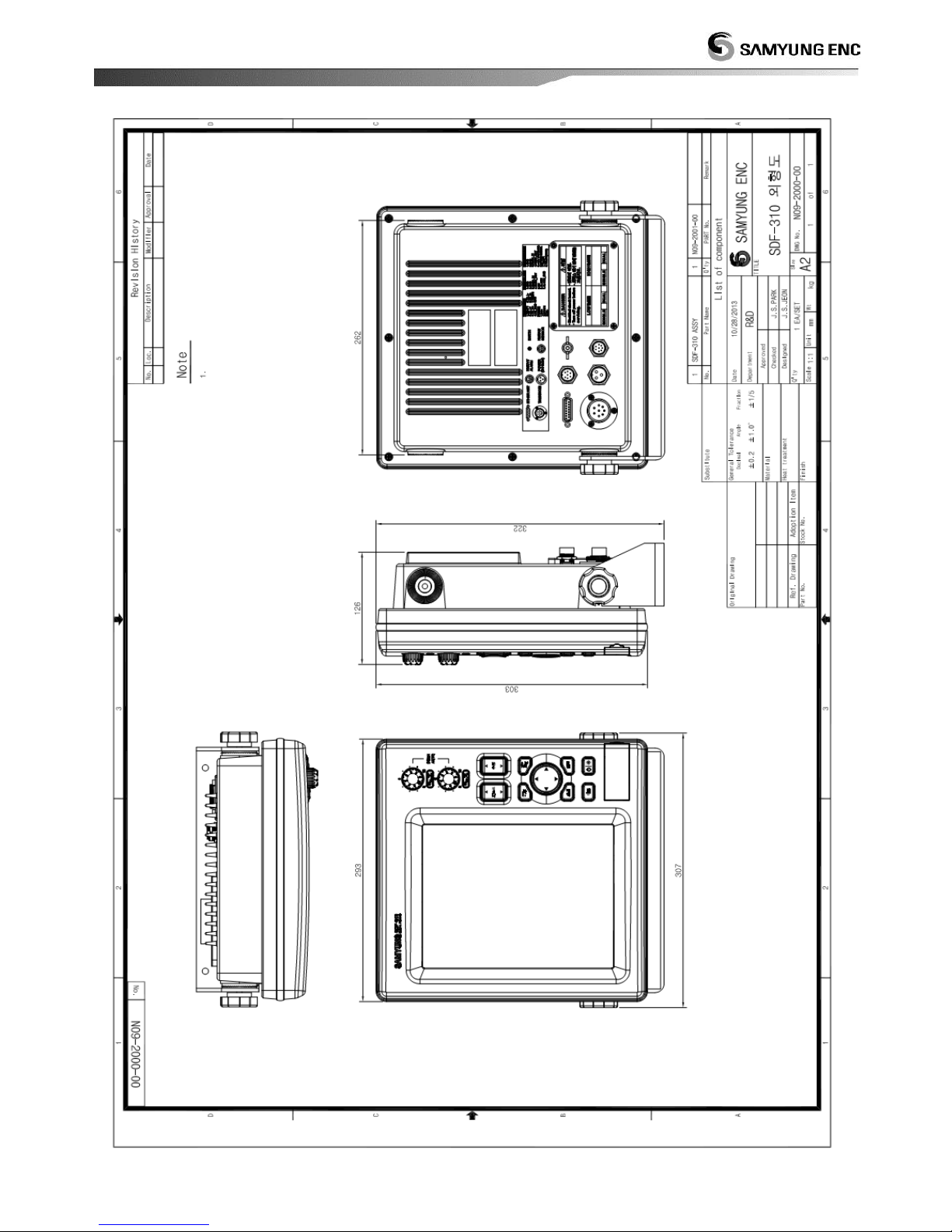
Weight & dimension : 5.2Kg , 307mm X 321.5mm X 135.3mm
(Width X Length X Height)
Operation environment
Temperature : Main equipment = -15℃~+55℃
Humidity : Less than 93% (+30℃~+60℃)
Page 12
12
3. Functional specification
Display
Display color : 8 / 16 / 64 ,
Background: selectable among 5 colors
Range : 5~3000m, Shift : 0~2000m
Extension range : 5~200m of whole range
Display mode : Single, Dual, Extension Dual, A-scope
Zoom mode : Bottom lock, Bottom zoom, Marker zoom
Speed : x4 , x2 , x1 , 1/2 , 1/4 , 1/8 , Stop
Alarm : Water depth, Fish, Water temperature
Noise reduction : Off, Light, Medium, Strong or Frequency adjustment
(Range depends on transducer)
Auto display : Auto gain (fishing/sailing), Auto depth,
Water temp. graph, Battery voltage, Water
temp., Display speed
Interface
Number of port : NMEA0183 Ver1.5/ 2.0 / 3.0 (I/O) -2 port
Input data : Will be updated
Output data : DPT, Will be updated for the rests
Page 13
13
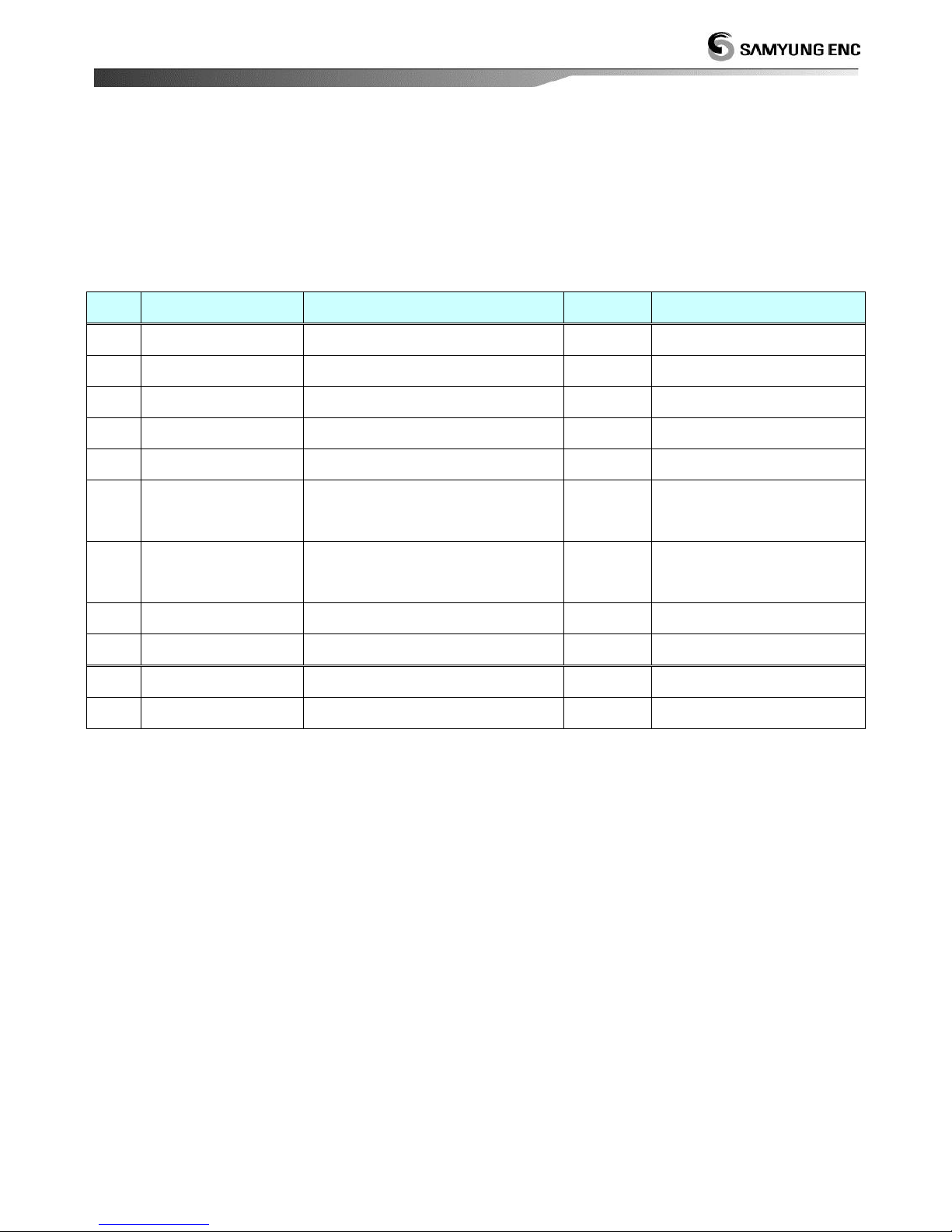
4. Component
SDF-310 Fish finder
No.
Description
Part number
Q/ty
Remark
1
Main unit
SDF-310
1EA
2 DC cable
SCN3-5M-FUSE Cable Ass’y
1EA
3 Fuse
DC+(24V)/5A , DC-(24V)/7A
1EA/1EA
4 Spare fuse
24V/5A , 12V/7A
3EA/3EA
5 DATA connector
SCN-16-7P
1EA
6
Transducer
connector
SCK-25-8P
1EA
When connect with own
transducer of vessel
7
Installation
accessory
1SET
8
Operation manual
1EA
9 Easy manual
1EA
+
Page 14

14
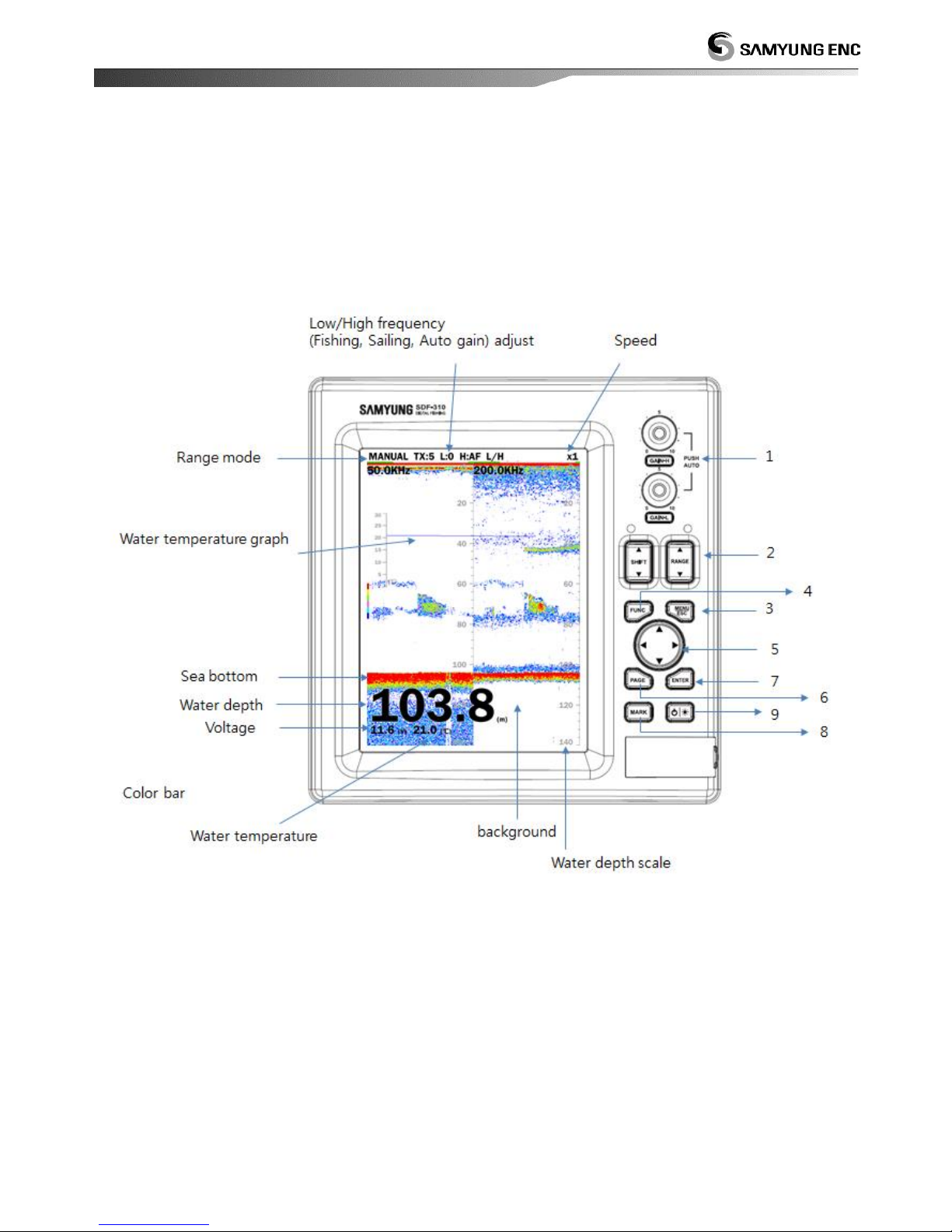
This chapter explains about SDF-310 equipment and display.
Display description
Power ON/OFF
Menu tree
Screen mode
3
Description
Page 15
15
1 Display description
Page 16
16
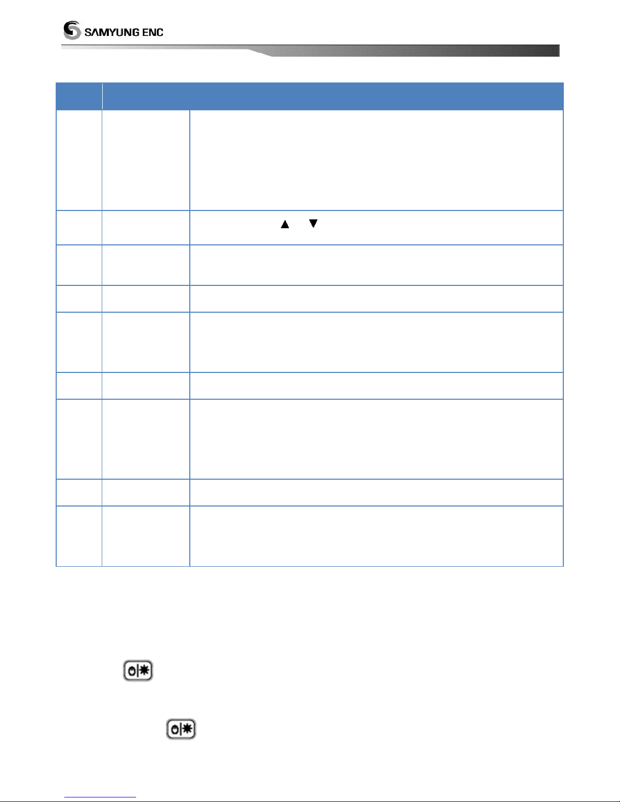
No.
Key/Button
Description
1
Adjust gain
Gain-High : Adjust High frequency.
Gain-low : Adjust low frequency.
Push the button : change the gain mode auto or manual.
In manual mode, rotate the button to left: decrease the level ,
to right: increased the level.
2
Shift/Range
Adjust by using or .
(This function is not available in Auto shift , Auto range mode)
3
Menu/ESC
Open/Close the menu
Escape from current operation.
4
Func
Please read 6.3 Func key.
5
Cursor
Move in the menu list.
Set the level of adjustment
Move VRM marker.
6
Screen
Choose the screen to display.
7
Enter
Choose and apply the menu.
Open the next submenu list.
At Fish finder screen : Show screenshot image (maximum 10
images)
8
Mark
Input waypoint
9
Power
Short press : Turn the power on / Open the Brightness setting
menu.
Long press : Turn the power off.
2 Power ON/OFF
Power ON
Press the button. About 2 seconds later, Samyung company logo is displayed and fish
finder is available.
Power OFF
Press and hold button for 5 seconds.
Page 17
17
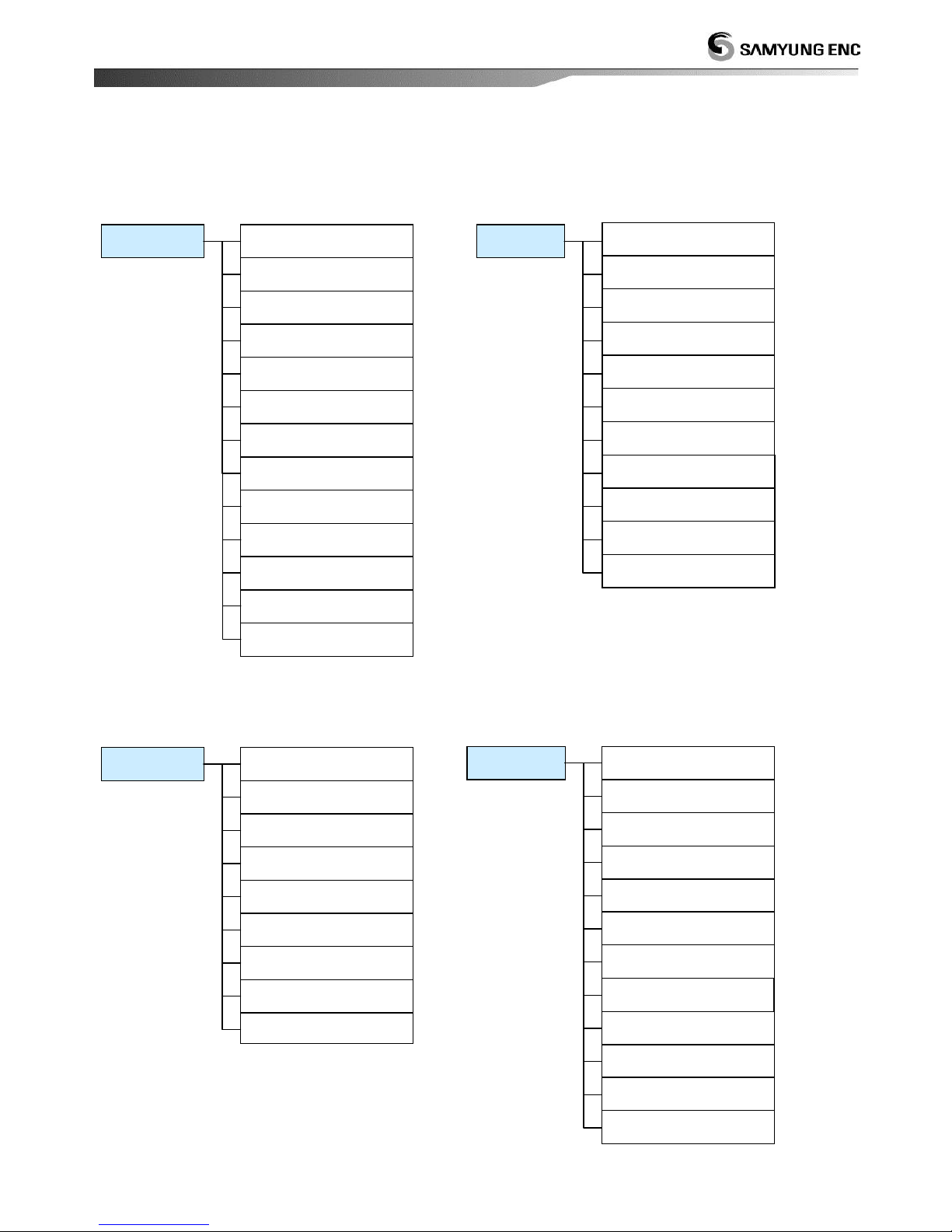
3 Menu tree
2. DISP.
1. Mode
2. Range
3. Auto Range
4. Display Speed
5. Interference
6. Noise Reduction
7. Refresh Area
8. TVG
9. STC
10. Gain Offset
11. Auto Gain Offset
1. Day/Night
2. Color
3. Hue
4. Background
5. Color Erase
6. Clutter
7. White Line
8. White Line Color
9. Temp. Color
3. COLOR
1. TX Power
2. TX Rate
3. Pulse Edge (L)
4. Pulse Edge (H)
5. Pulse Length (L)
6. Pulse Length (H)
7. Freq. Setting (L)
8. Freq. Setting (H)
9. Freq. Adjust (L)
10. Freq. Control (H)
1. SONAR
11. TX Fix
12. Bottom Search
13. Trigger Sweep
1. Direction
2. Division
3. A-scope
4. Depth Size
5. Depth Scale
6. Help
7. Color Table
8. Temp. Graph
4. VIEW
9. Detection Area
10. Header Info
11. Units (Depth)
12. Units (Temp.)
Page 18
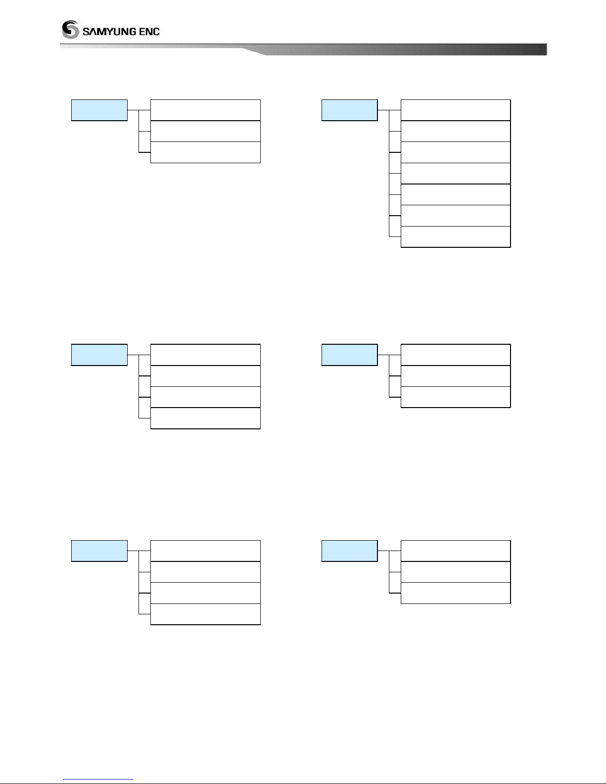
18
1. Magnification Mode
2. Partial Magnification Start
3. Partial Magnification End
4. Bottom Magnification Length
7.
1. Depth
2. Water Temp.
3. Fish School
5. Alarm
1. Fish School Display
2. Fish School Filter
3. Fish School Sensitivity
8. Fish school
1. NMEA Output
2. UART1
3. UART2
4. UART Monitor
9. NMEA
1. Language
2. Key Beep
3. Function Key
4. Push Button
5. Simulation
6.Others
6. Version Info
7. Factory Reset
1. Water temperature
2. Voltage
3. Beam Angle
10. Correction
Page 19
19
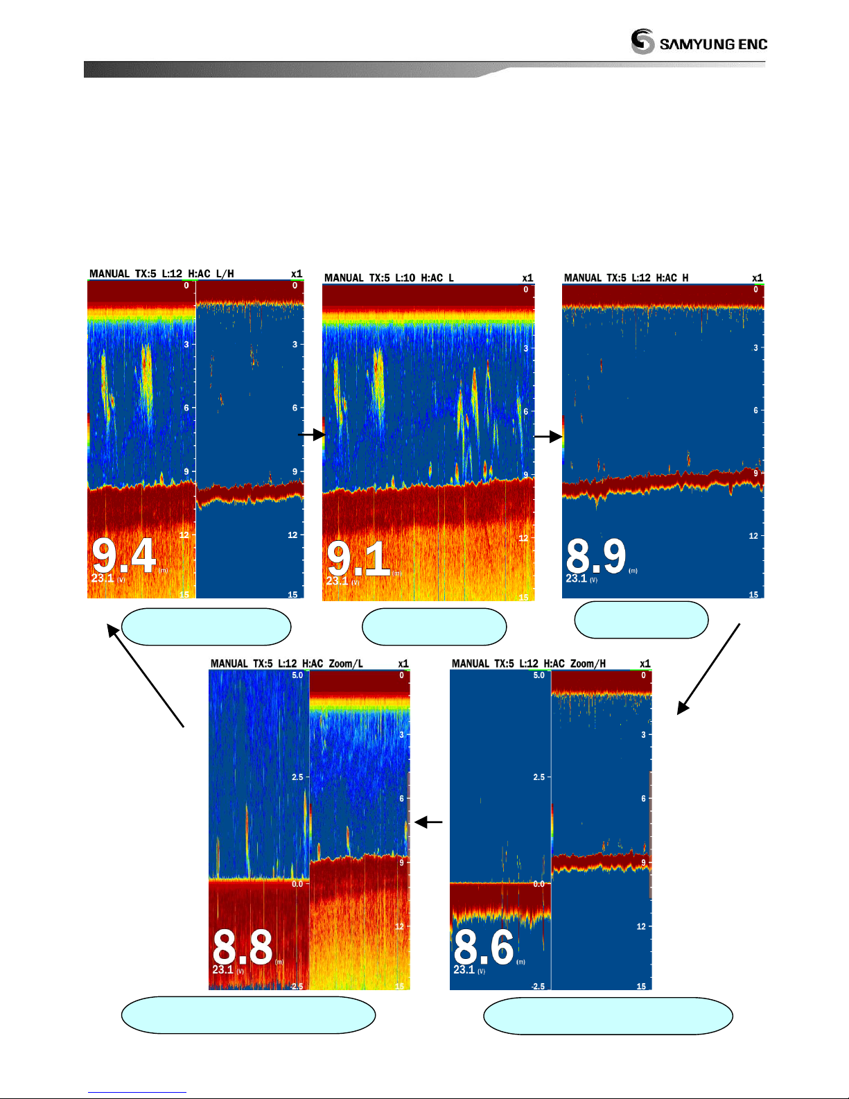
4 Screen Mode
The fish finder provide unique display mode for each mode.
Press Screen button to select a desired screen mode.
Screen mode switch
Low +high frequency
Low Frequency
High Frequency
Magnification Screen + Low Frequency
Magnification Screen + High Frequency
Page 20

20
This chapter explains the functions of SDF-310
Sonar
Image
Color
Display
Alarm
Others
User
4
Functions
Page 21
21
1. Sonar
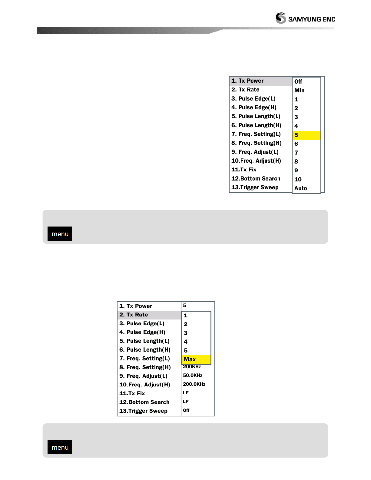
1.1 Transmitting (Tx)Power
If same frequency is used by near vessel’s fish finder,
there could be interference noise in the display. If there is
an anyway to reduce other’s fish finder’s output then the
interference noise can be suppressed. The transmitting
power can be adjusted manually and it can be changed
automatically. If you want to stop the transmitting, select
stop.
1.2 Transmitting (Tx) Speed
You can select transmitting speed. If you select smaller speed, the transmitting interval is
getting longer and the display time is getting long.
Setting for Transmitting (Tx) Speed
Select [Sonar] Select [Tx rate] Select desired speed
Transmitting (Tx) power setup
Select [Sonar] Select [Tx Power Select desired power
Page 22
22
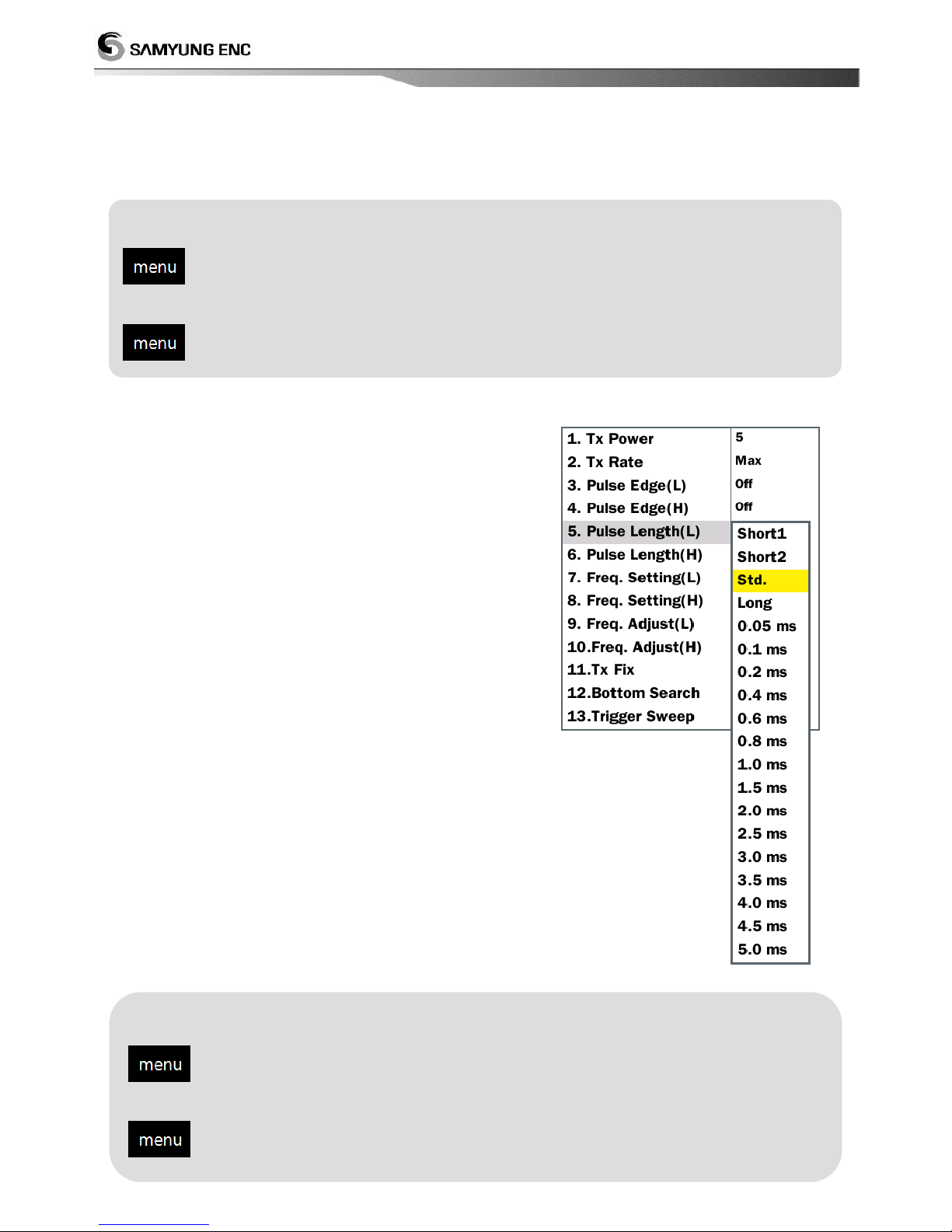
1.3 High resolution pulse
If you set it ON then, you can reduce your interference on other vessel.
1.4 Pulse Width
The pulse width is changing depending on range and
Shift but it could be set by manually. If you set short
pulse range, you can have better image and if you set
long pulse range, you can see deeper
If you want to have better image, set short1, short2.
Short1 : You can have a better Image but less depth
compare to short2.
Short2 : You can have better target image in short
depth.
Standard : In general, this can use used for various
fish search
long : Target image is not clear but search distance is
longer.
Setting for low frequency pulse edge
Select [Sonar] Select [pulse edge(L) (Select 『On or off』)
Setting for high frequency pulse edge
Select [Sonar] Select [pulse edge(H) (Select 『On or off』)
Setting for Low frequency pulse edge
Select [Sonar] Select [Pulse edge(L)] (Select 『On or off)
Setting for high Frequency pulse edge
Select [Sonar] Select [Pulse edge(H)] (Select 『On or off)
Page 23
23
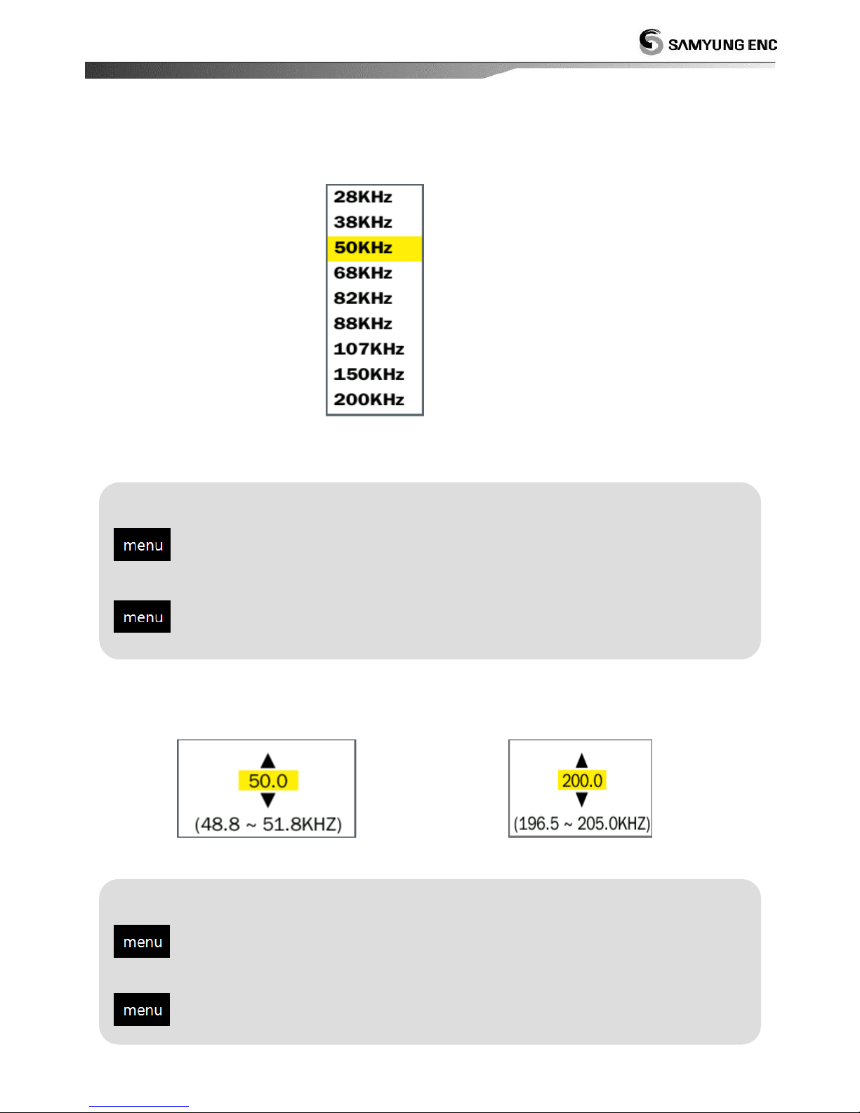
1.5 Frequency setting
Select a frequency to be displayed in high and low frequency screen.
<Frequency selection menu>
1.6 Frequency adjust
1.5 You can do fine tune the selected frequency in the frequency selection
<When select low frequency 88KHz> < When select high frequency 200KHz >
Setting for Low frequency
Select [Sonar]Select [Frequency adjust (L)]Change to a desired value
Setting for High frequency
Select [Sonar]Select [Frequency adjust (H)]Change to a desired value
Setting for Low frequency
Select [Sonar] Select [Freq. Setting(L)] Change to a desired value
Setting for high frequency
Select [Sonar] Select[Freq. Setting(H) Change to a desired value
Page 24
24
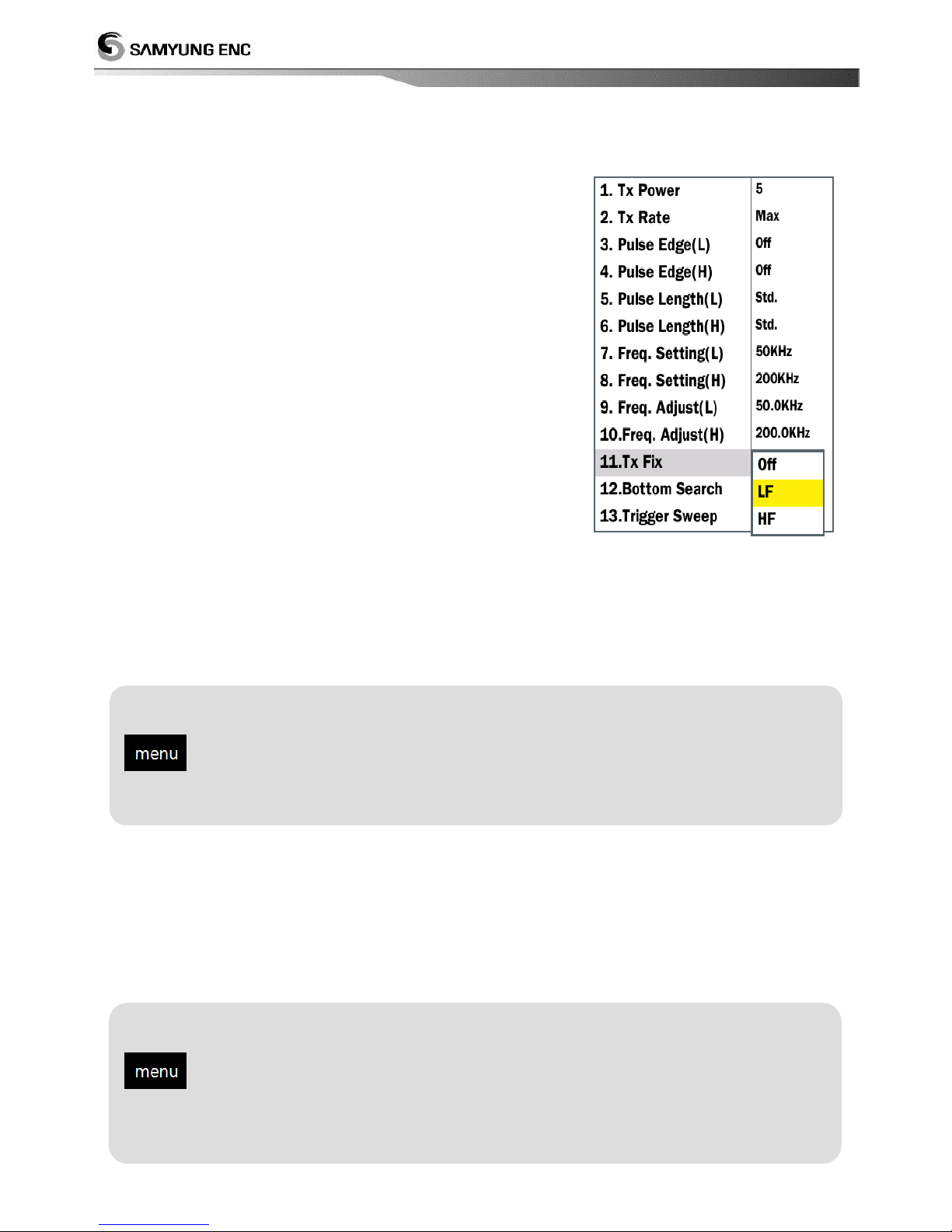
1.7 Fixed Transmission (Tx Fix)
Below is the transmission/receiving fixed type according to
transducers.
- Low frequency: transmit and receive low frequency & high
frequency in order using the low frequency transmitter.
- High frequency: transmit and receive low frequency &
high frequency in order using the hig frequency transmitter.
- OFF : Use all low and high frequency transmitter in order.
Low frequency use low frequency transmitter and
high frequency use high frequency transmitter.
Low frequency or high frequency setup can be set
when a transducer is connected to single line (two
lines, shield)
OFF setup can be set when a transducer is connected to dual line (four lines, shield) or
when low frequency transducer and high frequency transducer is used separately.
Above setup need to be set by authorized distributor.
1.8 Depth Calculation Frequency
Frequency which can display the depth of water in the screen can be selected. If automatic is
selected, low frequency’s depth is display preferentially
Setting for Fixed transmitting
Select [Sonar] Select [Tx Fix] Select a desired fixed transmitting
frequency
Setting for Depth Calculation frequency
Select [Sonar] Select [bottom search] Select a desired frequency
Page 25
25
1.9 Trigger Sweep
This can reduce electrical interference noise of other vessel by transiting signal irregularly
Setting for Trigger Sweep
Select [Sonar] Select [Trigger Sweep] (Select 『ON/OFF)
Page 26
26
2. Display
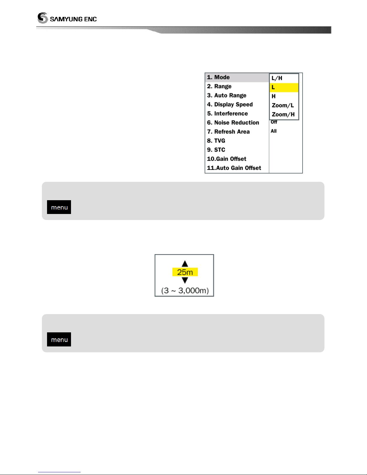
2.1 Mode
It can set a screen display mode.
2.2 Range
Range value can be changed by shift key and range key.
Setting for Mode selection
Select [Display] Select [Mode] Select a desired display mode
Setting for Range setup
Select [Display] Select [Range] Select a desired range value
Page 27
27
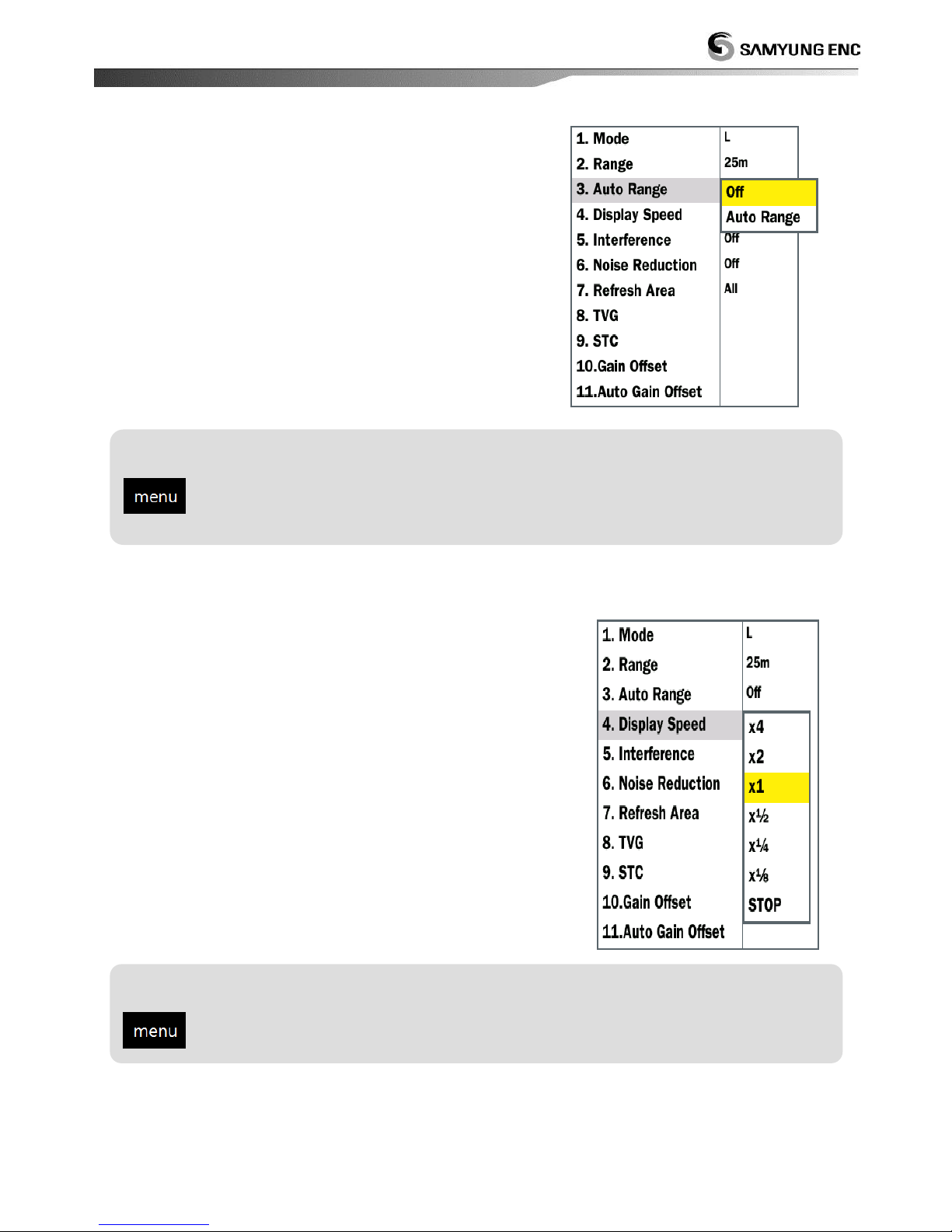
2.3 Auto Range
Range can be adjusted manually or automatically.
Automatic adjustment is useful when you are
preoccupied with other tasks and do not have the time
to adjust the display.
2.4 Display speed
The picture advance speed determines how quickly the
vertical scan lines run across the screen. When choosing a
picture advance speed, keep in mind that a fast advance
speed will expand echoes horizontally on the screen and a
slow advance speed will contract them. A fast advance
speed is useful for observing the rugged bottom closely. A
slow advance speed is useful for observing the smooth
bottom.( Maximum speed X 8 , Minimum Speed X 1/8
Setting range
select [display] select [auto range] (select among 『off/auto range』
Setting for display speed
select [display] select [display speed] select desired speed
Page 28
28
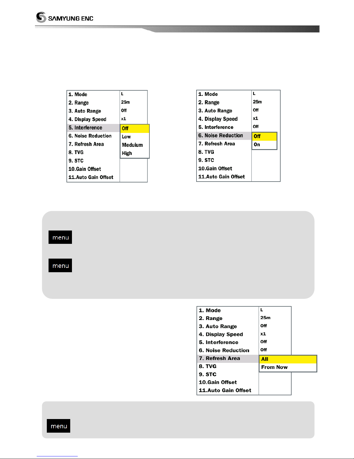
2.5 Interference
Their induced noise from the electric apparatus and the occurrence of periodic interference
from the lineup of a fish finder is the ability to eliminate noise.
< Interference> < noise reduction>
2.6 Refresh area
Change from the current value, whether, as a
whole should choose.
Setting for interference
select [display] select [interference] select desired level
Setting for noise reduction
select [display] select [noise reduction] select among 『off/on』
Setting for refresh area
select [display] select [refresh area] (select among 『all/from now』
Page 29
29
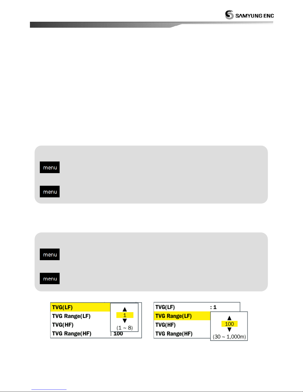
2.7 TVG
A fish school at a deep depth is displayed in weak colors even if it is equal in strength to one
in shallow waters. This is due to propagation attenuation of the ultrasonic wave. To
compensate for this difference, use TVG. TVG automatically adjusts the gain with depth so that
echoes of the same strength and different depths are shown in the same colors regardless of
their depths. Do not set the TVG too high; close-range echoes may not be displayed
2.7.1 Setting for TVG level
Set-up for TVG level. Do not set the TVG too high; close-range echoes may not be displayed
2.7.2 TVG거리 Setting for TVG distance
TVG set up for applied distance.
< TVG level> < TVG distance >
Setting for low frequency TVG
select [display] select [TVG(L)] select desired level
Setting for high frequency TVG
select [display] select [TVG(H)] select desired level
Setting for low frequency TVG distance
select [display] select [TVG distance(low)] select desired distance
Setting for high frequency TVG distance
select [display] select [TVG distance(high)] select desired distance
Page 30
30
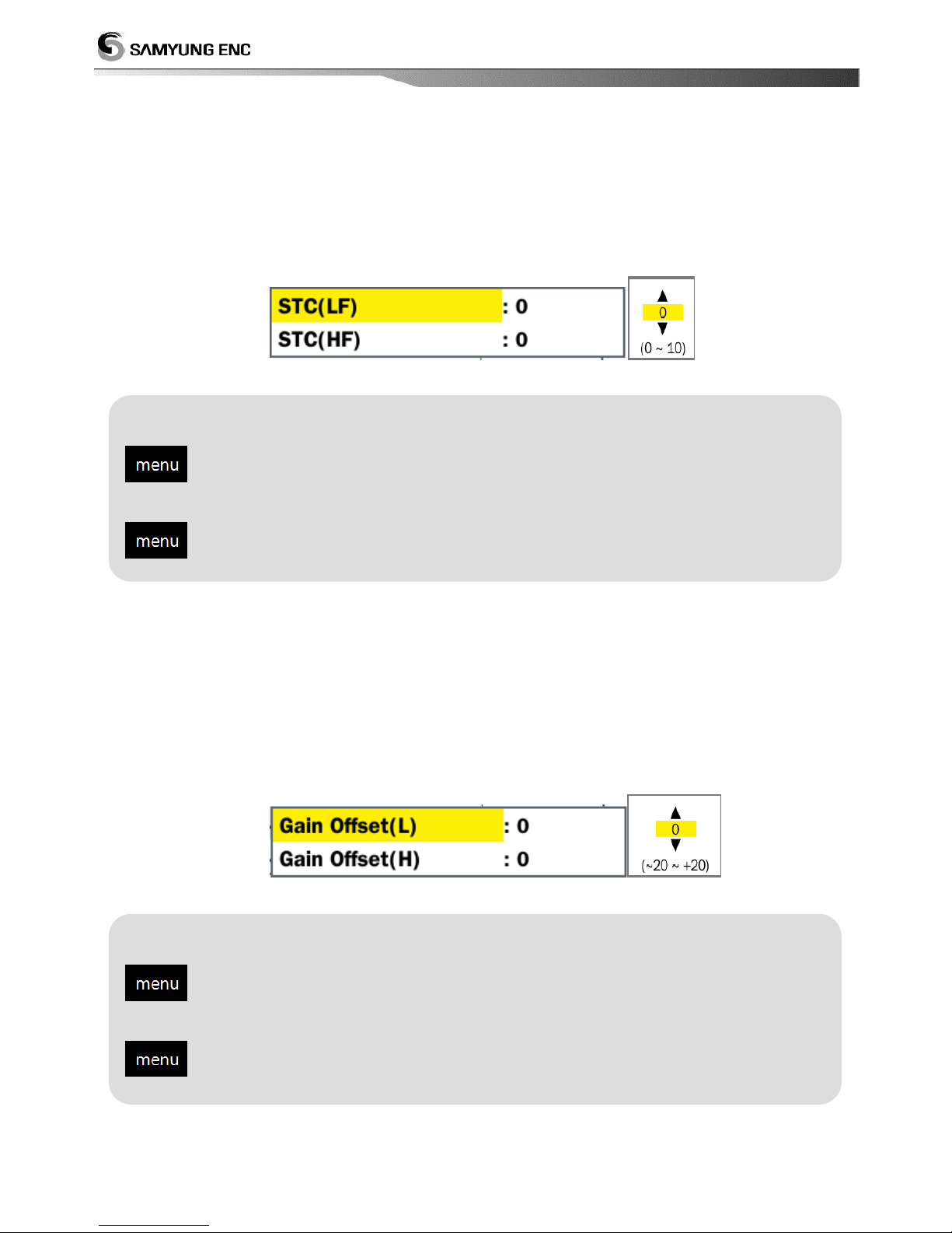
2.8 STC
This is useful to clear the surface of unwanted echoes to look for surface fish. The setting
range is 0-10, and 0 is Off. In setting 10, STC deletes unwanted echoes from the surface to
about 5m. Avoid setting the STC too high; fish echoes near the surface may be erased.
2.9 gain offset
If you want to increase or decrease the sensitivity or to control the sensitivity balance between
low frequency and high frequency, you can set offset value. If sensitivity setting value is so
small, weak signal is suppressed, then there’s no image. If the values is so big, it will be
difficult to identify the images because of noise. So you should control the gain.
Setting for low frequency STC
select [display] select [STC(low)] select desired value
Setting for high frequency STC
select [display] select [STC(high)] select desired value
Setting for low frequency gain offset
select [display] select [gain offset(L)] select desired value
Setting for high frequency gain offset
select [display] select [gain offset(H)] select desired value
Page 31
31
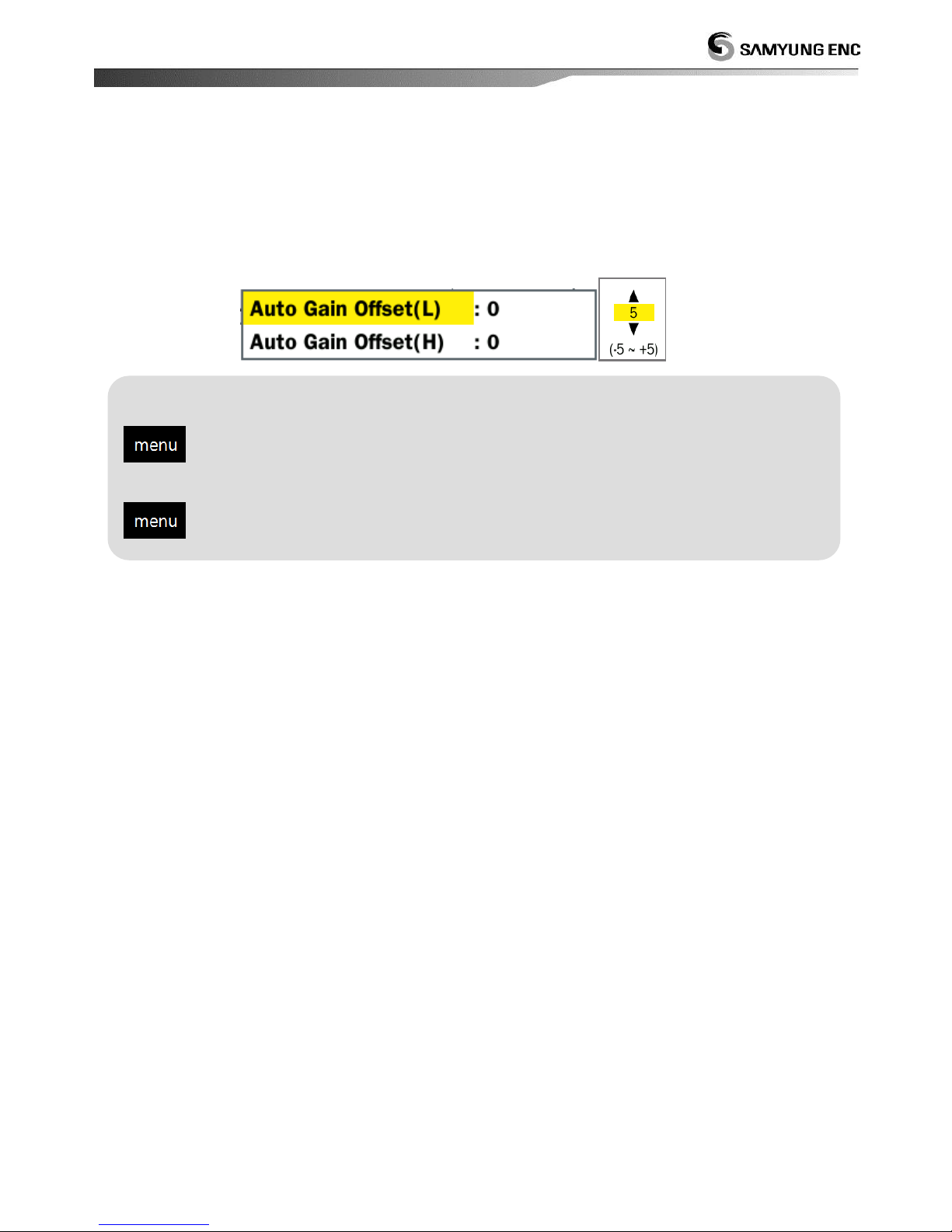
2.10 Automatic gain offset
In automatic operation, seabed is automatically adjusted as reddish-brown color. You can
modify offset value to set the sensitivity up or down in automatic gain. Clutter function
operate automatically to eliminate small echo by dirt seawater and plankton. This allow good
picture to identify.
Setting for auto gain offset of low frequency
select [display] [auto gain offset(L)] select desired value
Setting for auto gain offset of high frequency
select [display] [auto gain offset(H)] select desired value
Page 32
32
3. Color
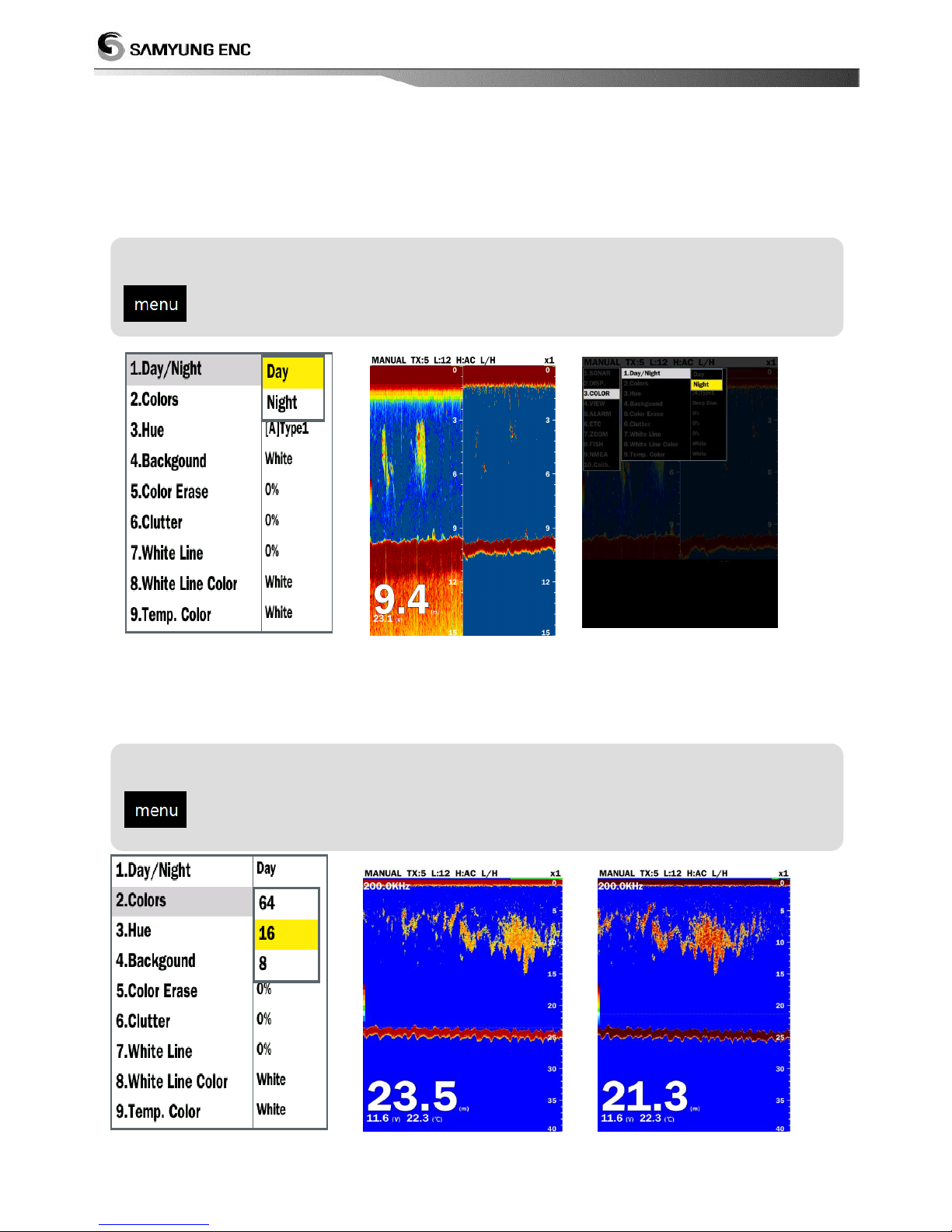
3.1 day/night
It can change the menu and background color of the screen. When you select day, the screen
is bright and menu is white. When you select night, the screen is dark and menu is black.
<day/night > <day> <night>
3.2 number of colors
It can select the number of colors
<number of colors> <screen of 8 colors> <screen of 64 colors>
Setting for day/night
select [color] select [day/night] select among 『day/night』
Setting for number of colors
select [color] select [number of colors] desired number of colors
Page 33
33
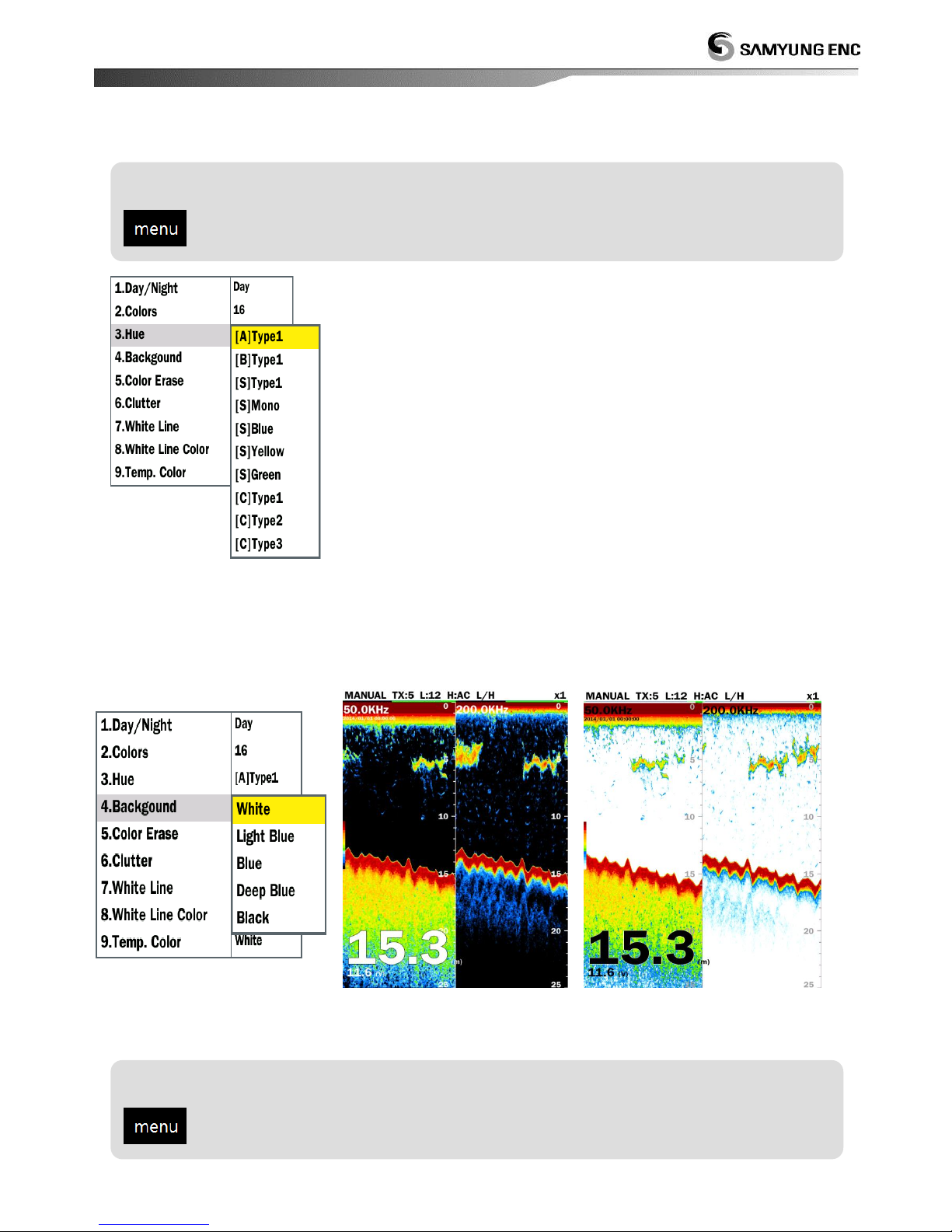
3.3 hue
It can select the hue of pictures according to brightness and taste
<hue>
3.4 background color
It can change background color according to the surrounding environment
<background color> <black> <white>
tone
select [color] select [hue] select desired hue
Setting for background color
select [color] select [background] select desired color
Page 34
34
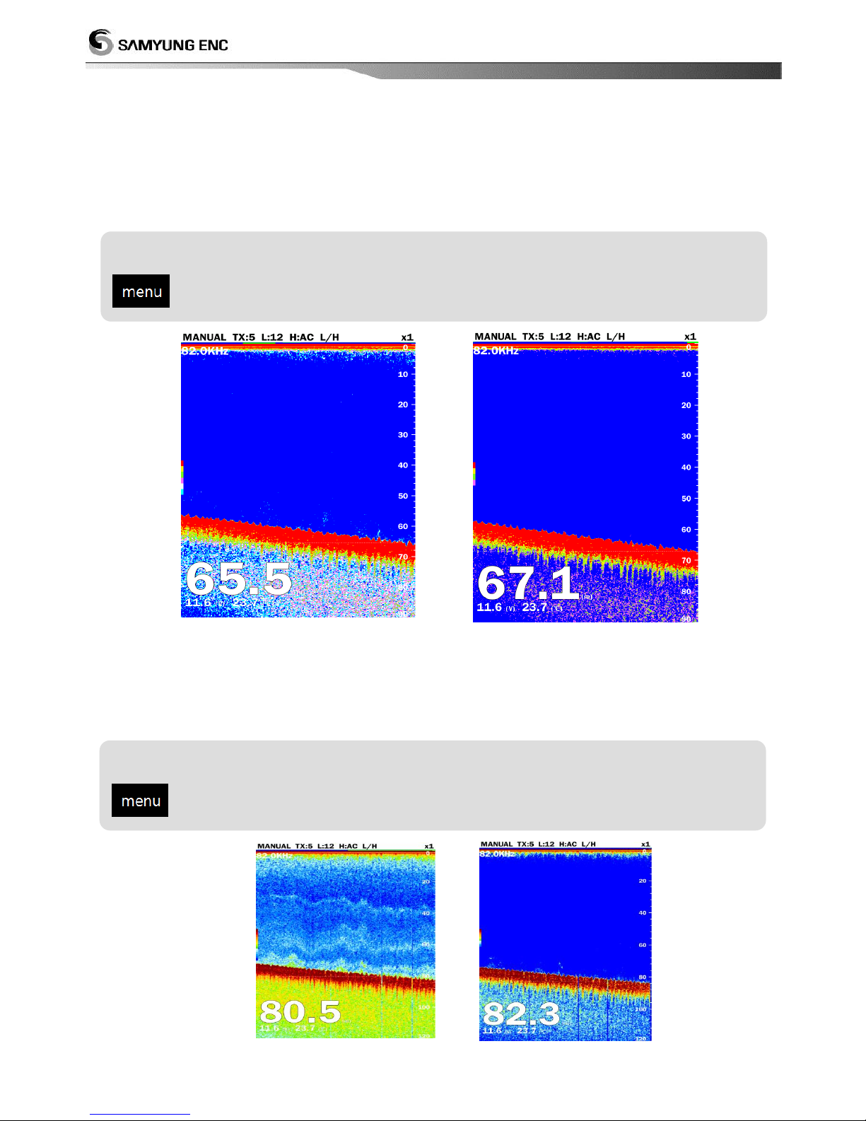
3.5 Color erase
Needless dim noise can be eliminated by color erase
Because this function removes unwanted low level echoes off the screen by cutting them off,
it is effective when the image is difficult to see because of interference or when you want to
see only big fish school
<without color erase> <removal of 50% color>
3.6 clutter
Clutter is used to eliminate low level return echoes because of dirt sea water etc. so one can
see clear fish school.
<without elimination of clutter><elimination of 40% clutter>
Setting for color erase
select [color] select [color erase] select desired values (0 ~ 50 %)
Setting for clutter
select [color] select [clutter] select desired value (0 ~ 80%)
Page 35
35
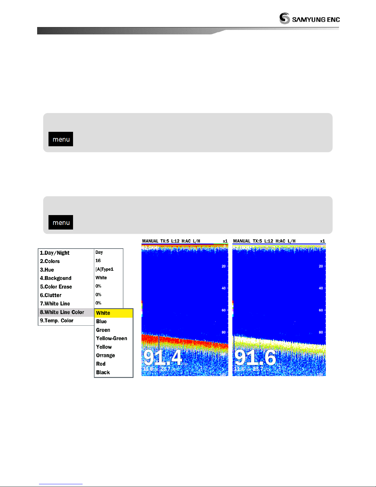
3.7 White line
White line allows you to identify easily between fish school on the bottom and seabed. The
strong colors (seabed, big fish school, high density fish school) are displayed as white band,
so it is not only helpful to identify seabed and fish school on the bottom but also in
determining the density of fish. The setting range is from 0% to 100%.
3.8 Color of white line
It can change the color of white line.
<color of white line > <without white line > <white line 100%>
Setting for white line
select [color] select [white line] select desired color(0 ~ 100%)
Setting for white line
select [color] select [white line] select desired color
Page 36
36
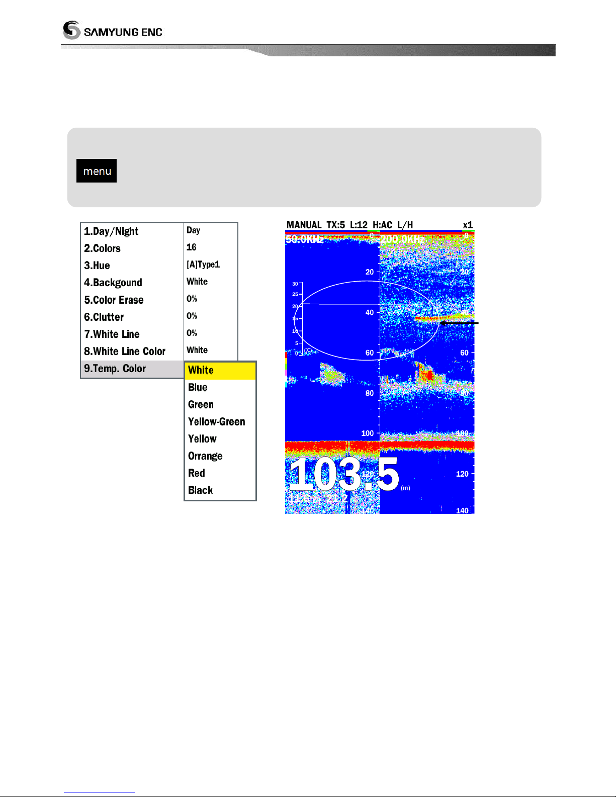
3.9 color of water temperature
Water temperature graph can be modified.
Setting for water temperature
select [color] select [temp. color ] select desired color
temperature
<Setting for color of temperature >
Page 37
37
4. View
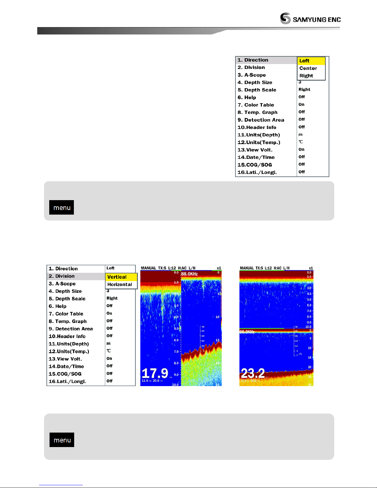
4.1 display direction
Select the display direction.
left : from right to left
right : from left to right
center : from center to two way left-right
4.2 Division
Select the division type for zoom and low/high frequency of screen
<menu of split screen> <vertical> <horizontal>
Setting for direction of display
select [view] select [direction] Select desired direction
Setting for division
select [view] select [division] (select among 『vertical/horizontal』)
Page 38
38
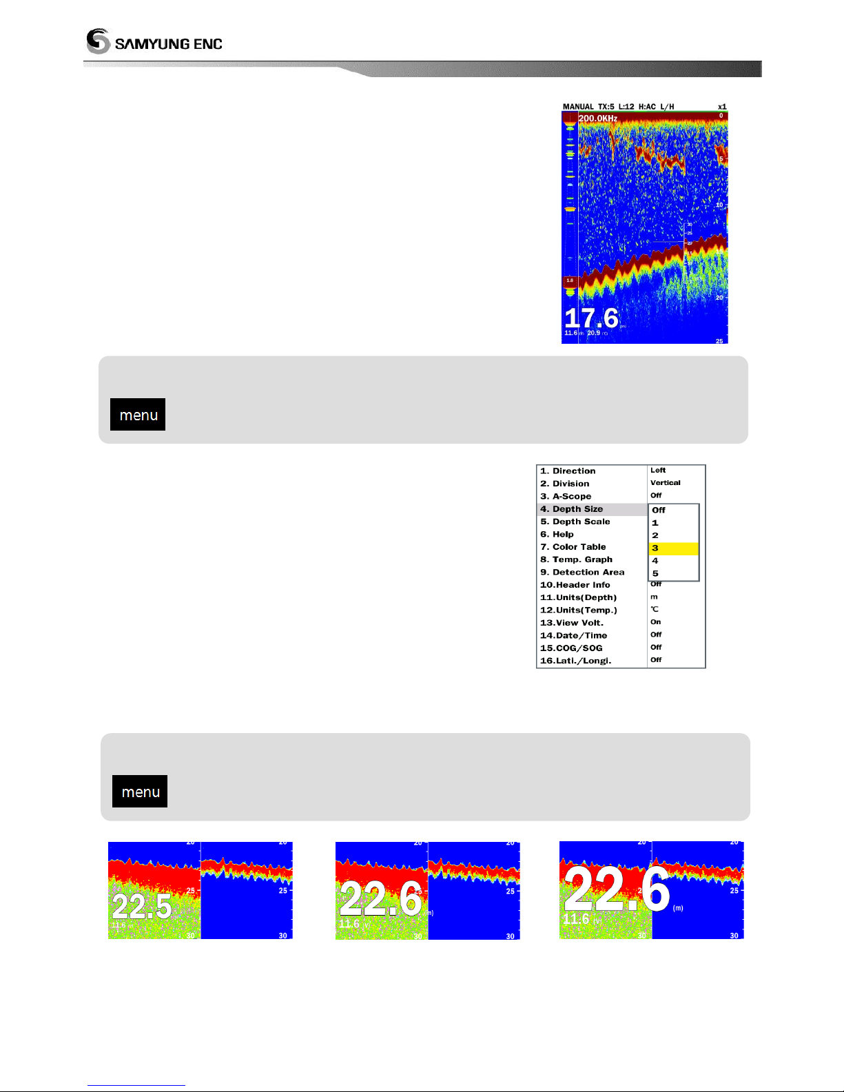
4.3 A-SCOPE
A-scope is the picture to show the strength of echo amplitude
on the right side of the screen. As A-scope display big amplitude
by big echo and small amplitude by small echo, it allows to
identify easily small fish school, sea bottom and geology.
4.4 depth size
Change the font size of water depth at the left bottom of the
screen
<small> <middle> <big>
Setting for A-Scope
select [view] select [A-Scope] (Select among 『Off/on』 )
Setting for depth size
select[view] select [depth size] select desired size
Page 39
39
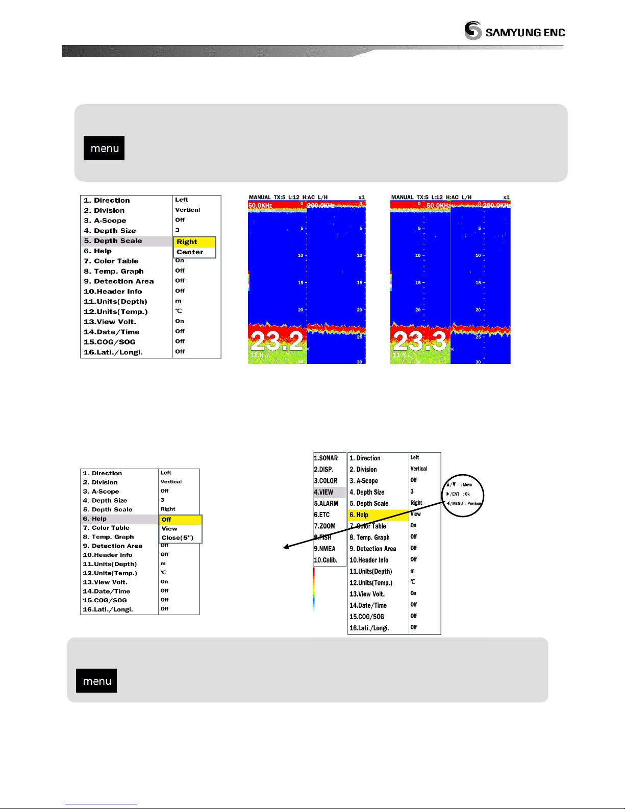
4.5 depth scale
It can modify depth scale
<setting for depth scale> <right> <center>
4.6 help
It can select whether it will explain the selected item or not
help
- Off : Do not show help
- On : Show help
- End(5 seconds) : If there’s no key control for 5 seconds, the help will be turned off automatically.
Setting for depth scale
select [view] select [depth scale] select desired direction
Setting for help
select [view] select [help] (select among『off/on/end(5 seconds)』
Page 40
40
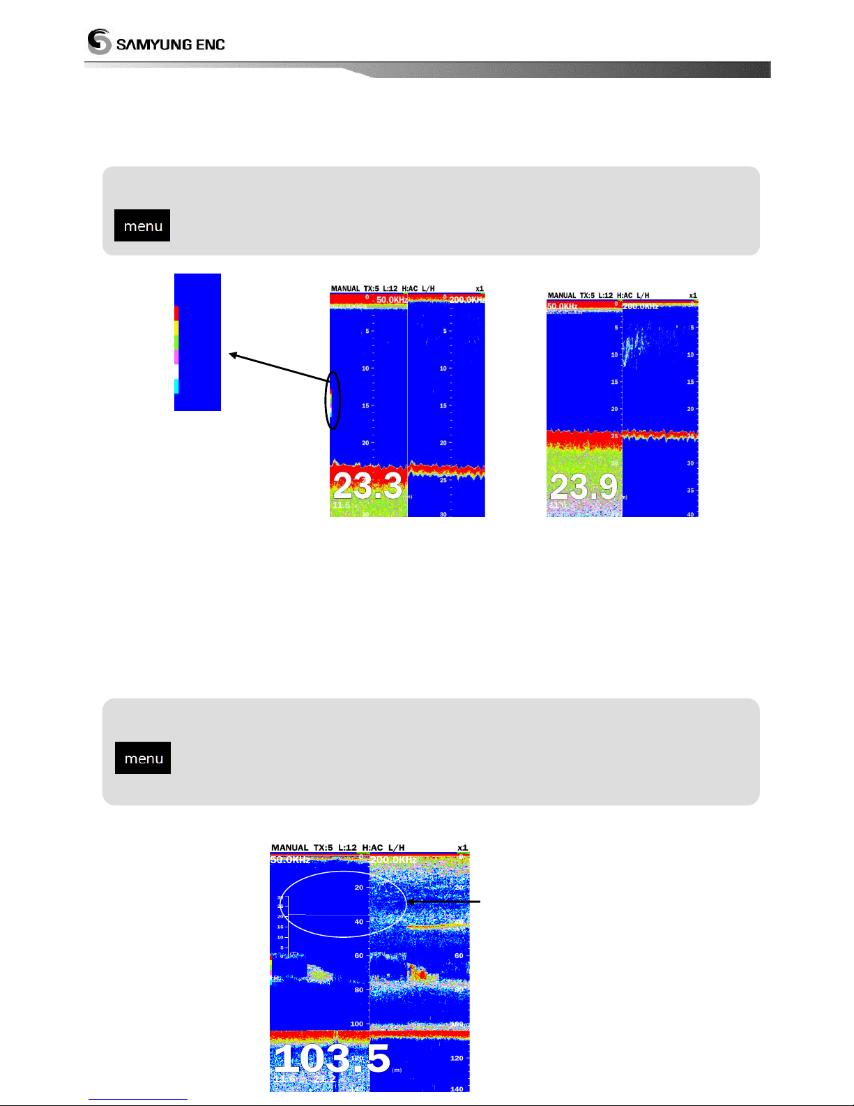
4.7 Color table
It can select whether it will show the color table on the right in the center of screen or not
<on> <off>
4.8 temperatures
It can select whether it will show water temperature or not. When displaying the temperature
graph, choose the width of the scale in step 2. (narrow : 8˚C, wide : 16˚C). And it needs
temperature sensor.
Setting for temperature
select [view] select [temperature] (select among 『off/on』)
Setting for color table
select [view] select [color table] Select among on/off
Water temperature
Page 41
41
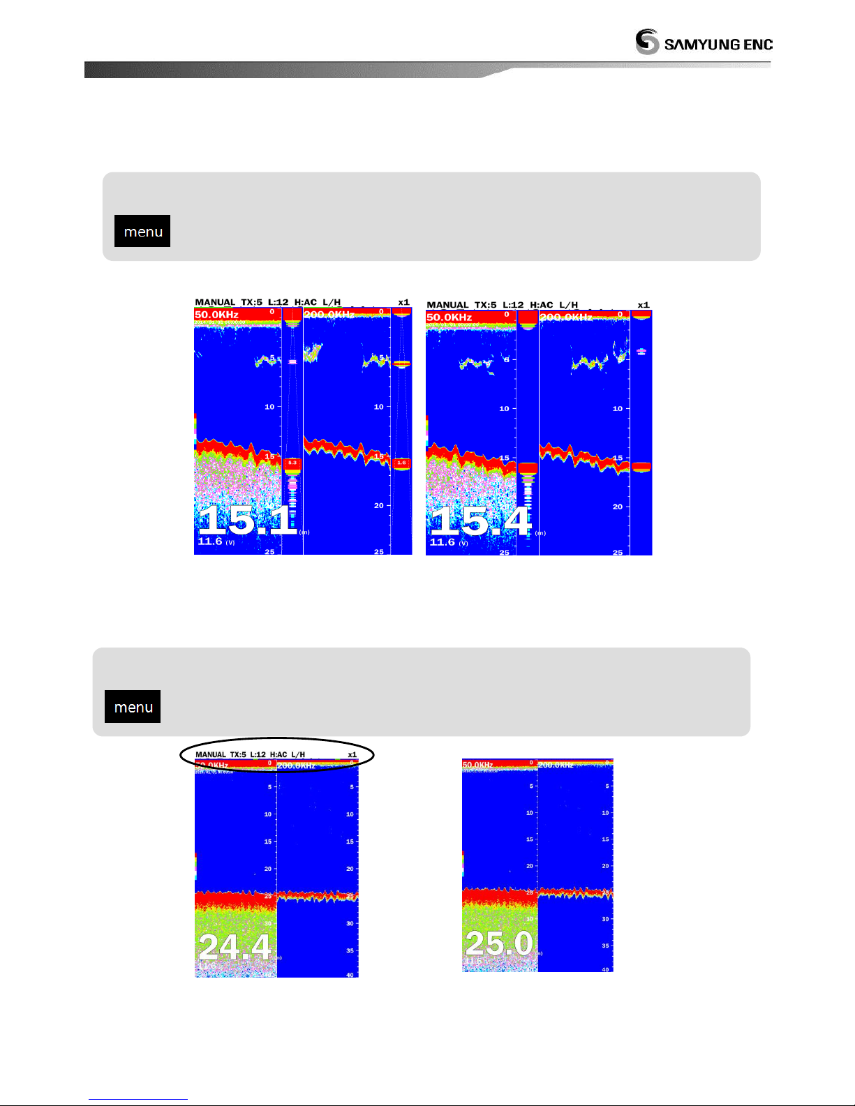
4.9 detection area
It can select whether it will show the detection range or not
<on> <off>
4.10 header info
It can select whether it will show the informations on top of the screen or not
<on> <off>
Setting for detection area
select [view] select [detection area] (Select among on/off)
Setting for information
select [view] select [header info] (Select among [on/off])
Page 42
42
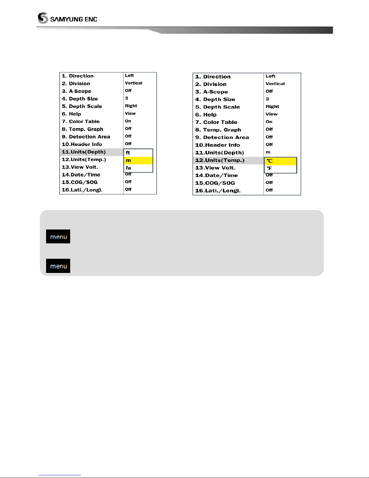
4.11 Setting for unit
Depth : select depth unit temperature : select temperature unit.
Setting for depth unit
select [view] select [unit(depth)] (Select among『ft/m/fa』)
Setting for temperature unit
select [view] select [unit(temp.)]
(Select among 『ºC/ ºF』)
Page 43
43
5. Alarm
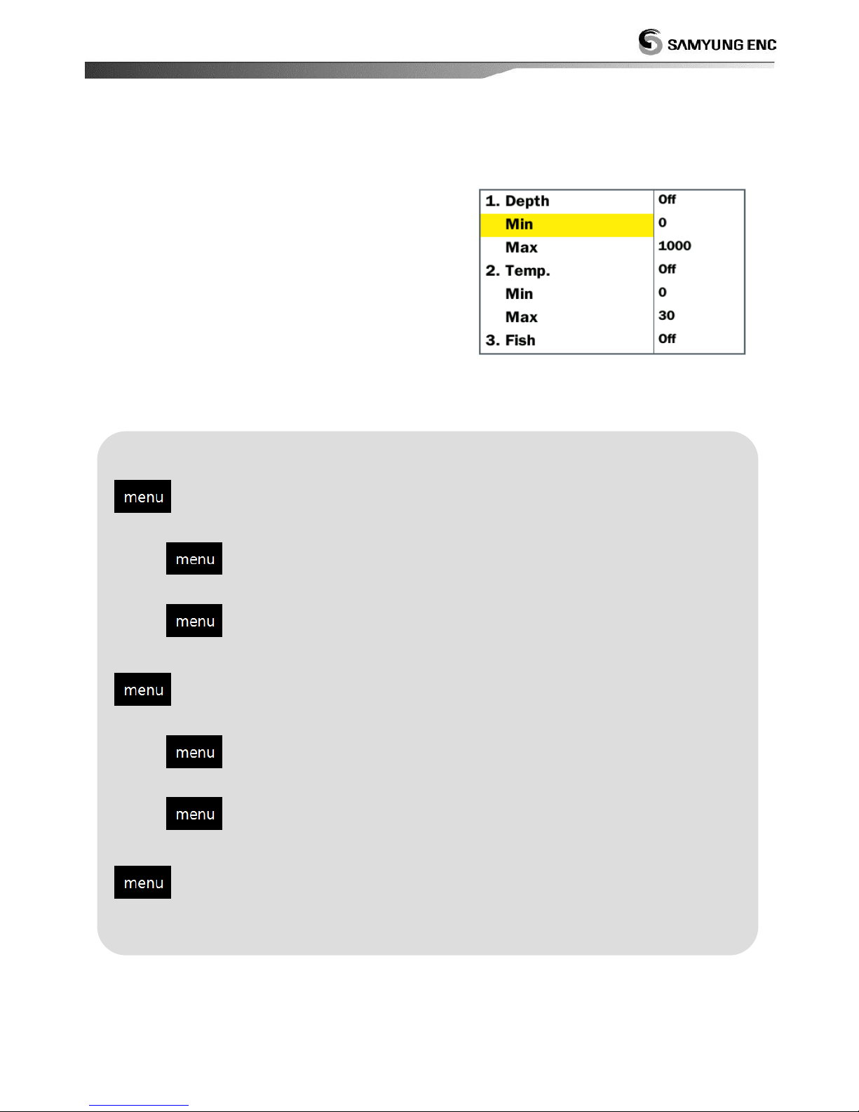
5.1 Setting for alarm
depth : when the depth is out of setting range,
alarm alerts you.
temperature : when the water temperature is out
of setting range, alarm alerts you.
Fish school :
When the fish school appear in setting range or
all range from the surface of transducer to sea
floor, alarm alerts you.
Setting for depth alarm
select [alarm] select [depth] (Select among 『off/on』)
setting for minimum depth
select [alarm] select [minimum] Select among 3~3000
setting for maximum depth
select [alarm] select [maximum] Select among 3~3000
Setting for temperature
select [alarm] select [temperature] (Select among 『off/on』)
setting for minimum temperature
select [alarm] select [minimum] Select among 3~3000
setting for maximum temperature
select [alarm] select [maximum] Select among 3~3000
Setting for fish school
select [alarm] select [fish school] (Select among 『off/on』)
Page 44
44
6. ETC
6.1 Language
The Language menu selects the language to use
6.2 sound of key beep
It can select whether it will ring or not.
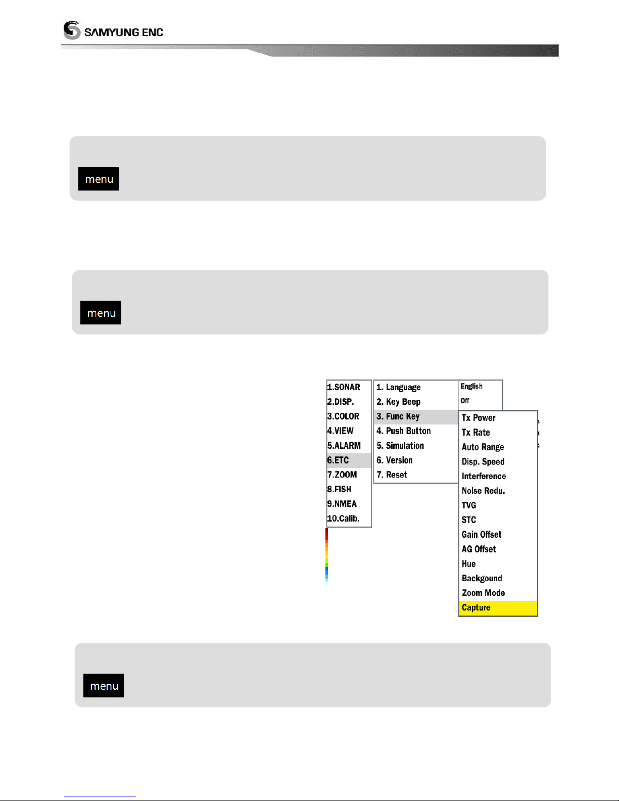
6.3 function key
There are Tx power, Tx Rate, Auto Gain, Display
speed, Interference, Noise reduction, TVG, STC,
Gain offset, Auto Gain offset, Hue, background,
Zoom mode, Capture in the function keys. If
the user register frequently used functions, the
operation is simple. Function key is set to a
TVG.
Setting for language
select [ETC] select [language] (Select among various languages)
Setting for key beep
select [ETC] select [key beep] select among『off/on』
Setting for function key
select [ETC] select [func key] Select desired operation
Page 45
45
6.4 Push Button
When the push button is off, Sensitivity will not be changed to automatic mode or manual
mode regardless the user push the button for sensitivity adjustment.
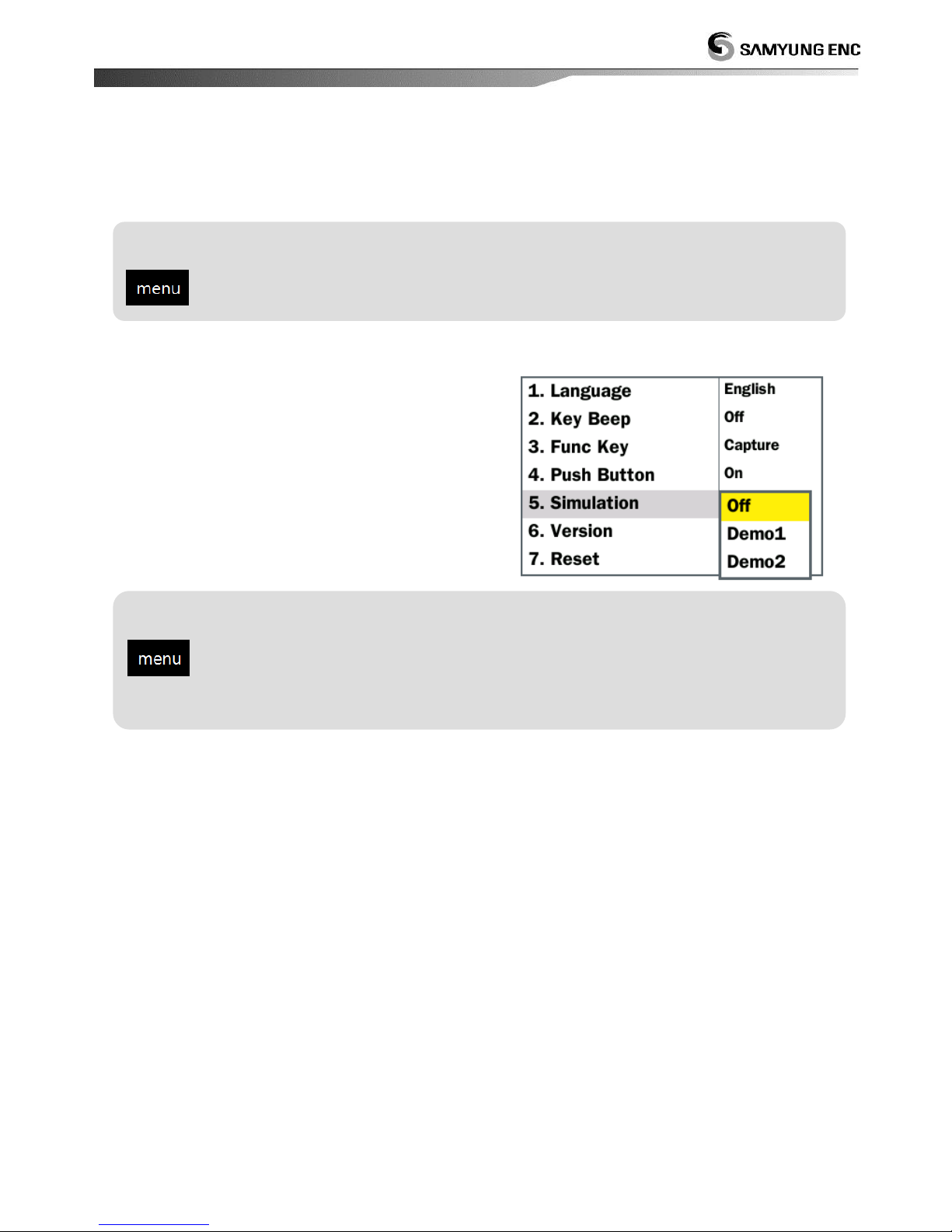
6.5 Simulation
It can select whether it will activate the simulation
mode or not
Setting for simulation
select [ETC] Select [Simulation] (Select among 『Off/Demo1/Demo2』)
Setting for Push button
select [ETC] Select [Push Button] (Select among『on/off』 )
Page 46
46
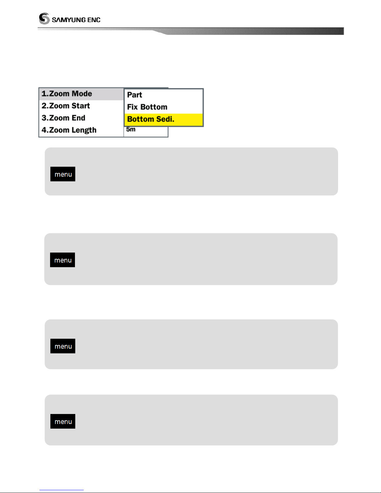
7. Zoom
7.1 Zoom mode
Select your desired zooming mode as belows;
7.2 Setting for zoom start
Select the starting point for partial zoom
7.3 Setting for zoom end
Select the ending point for partial zoom
7.4 Setting for zoom length
Select the size of zoom length
Setting for starting point of partial zoom up
select [user] select [zoom start] select between 3 and 3000m
Setting for ending point of partial zoom up
select [user] Select [zoom end] select between 3 and 3000m
Setting for zoom length
select [User] Select[zoom length] Select between 3 ~ 3000m(『3~
3000m』
Setting for Zoom mode
select [user] Select [Zoom mode] Select your desired mode
Page 47
47
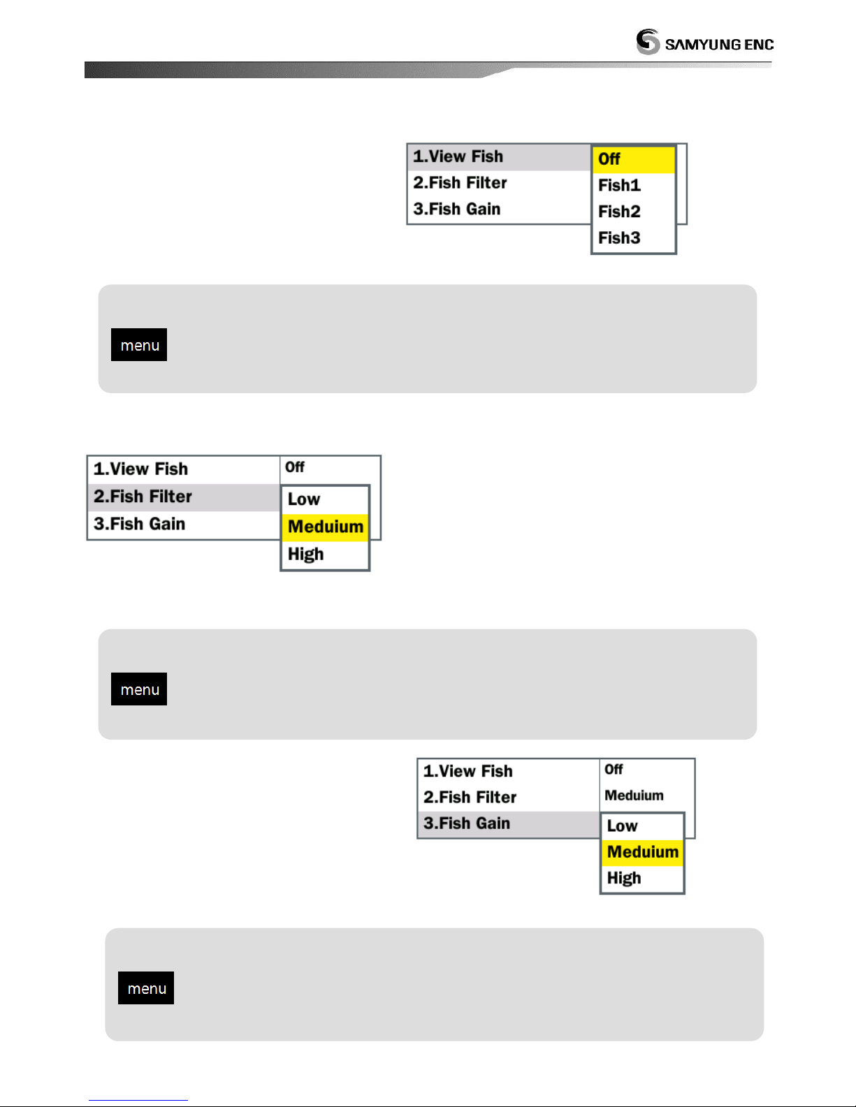
8. Fish Schools
8.1 Display of fish schools
Display fish schools.
8.2 Fish Schools filter
Setting for fish schools filter.
8.3 Fish Schools sensitivity
Setting fish schools sensitivity.
Setting for display of fish schools
select [Fish] Select [view fish] Select your desired display mode
Setting for fish schools filter
select [Fish] Select [fish filter] Select your desired filter level
Setting for fish gain
select [Fish] Select [fish gain] Select desired sensitivity level
Page 48
48
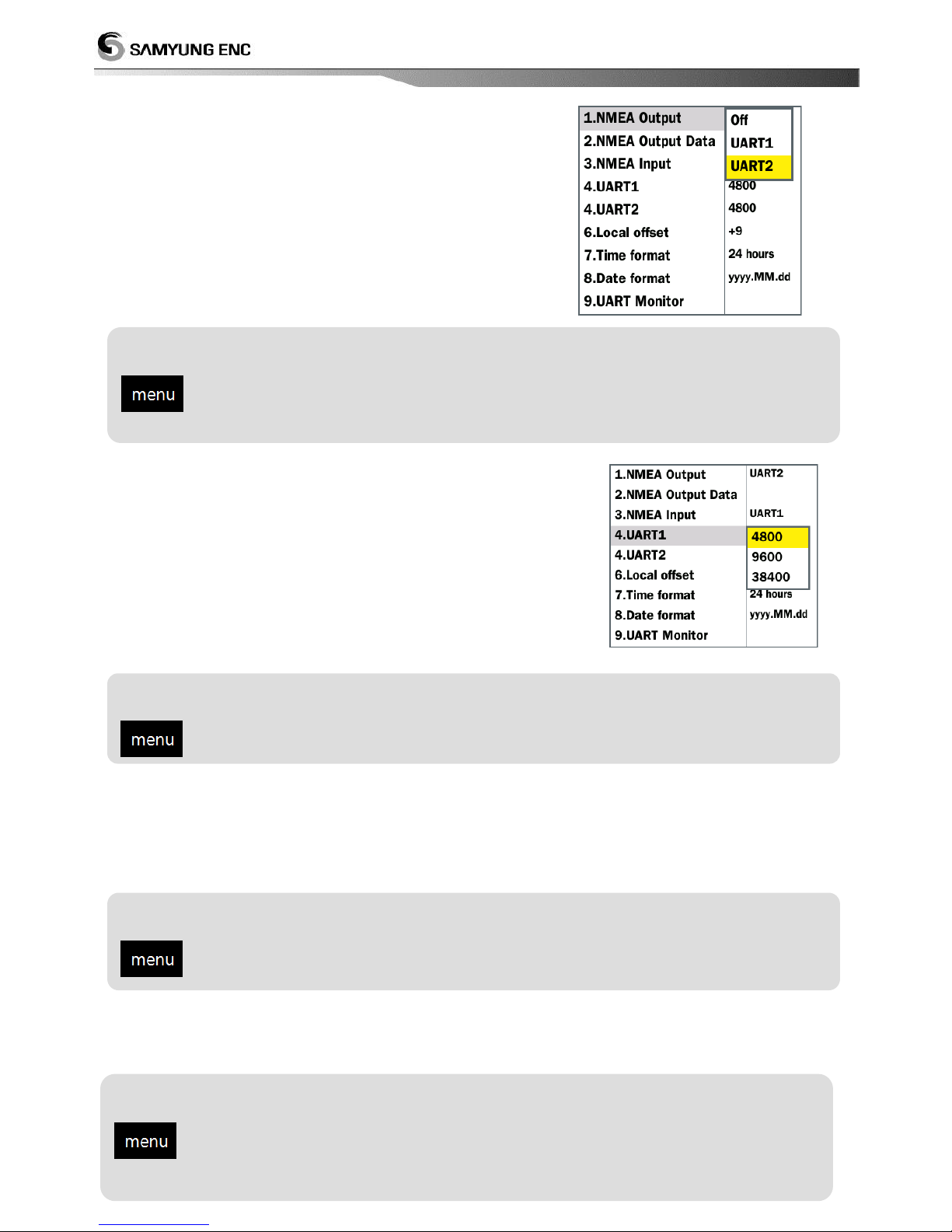
9. NEMA
9.1 NEMA Output
It will transmit DPT etc (ex water depth).among the
standard of NMEA0183 through RS-232C port. It will
transmit RS-232C once it is off.
9.2 UART1
Among RS-232C port from the main unit, it will transmit DPT
to NMEA1 port and receive GPS data. Speed can be set up
with 4800, 9600 or 38400
9.3 UART2
Among RS-232C port from the main unit, it will transmit DPT to NMEA2 port and receive GPS
data. Speed can be set up with 4800, 9600 or 38400
9.4 Monitor UART
Both of RS-232c port can be monitored
Setting for NMEA output
select [NEMA] Select [NMEA output] Select among OFF/UART1/UART2
Setting for UART1
select [NEMA] Select [UART1]
Select among 『4800/9600/38400』
Setting for UART2
select [NEMA] select [UART2] (select among『4800/9600/38400』)
Access UART monitor
select [NEMA] Select [UART monitor] To return press [menu]
Page 49
49
10. Modification
10.1 Temperature
Water temperature can be modified from -3 to +3
10.2 Voltage
Voltage can be modified from -3 to +3
10.3 Beam angle
Bean angle is frequency angle from transducer. Low frequency can detect wide area and
higher frequency can detect lower area. Bean angle can be modified from 4˚ to 26˚
Depending on beam angle, receiving radius of bottom can be displayed on A-Scope and
receiving radius can be changed depending on type of beam angle.
Setting for temp modification
select [calib.] Select [temp.] Select from -3 to +3
Setting for voltage modification
select [calib.] select [voltage] (select among 『-3~ +3』)
Setting for low frequency beam angle
select [calib.] select [beam angle(LF)] select among『4˚~ 26˚』
Setting for high frequency beam angle modification
select [calib.] select [beam angle(HF)] select among 『4˚~ 26˚』
Page 50

50
This chapter will explain the maintenance and defectiveness of SDF-310
Installation
Cable connection by the display
Connector pin arrangement from the back panel
Power supply connection
5
Connecting other devices
Page 51
51
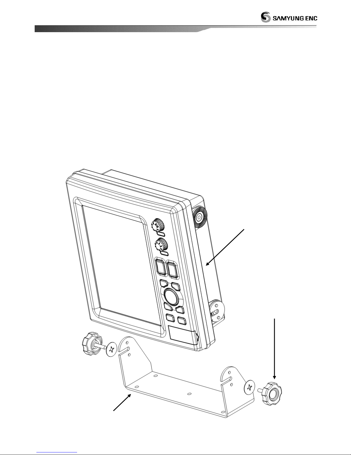
1. Installation
Installation of display bracket
1 Locate the bracket mounting on a proper location.
2 Hold the display unit and fix it with bolts
3 Insert bracket mounting bolts gently.
Separate display from bracket.
1 Switch off the device
2 Unwind bracket mounting bolts.
display
bracket mounting screw
bracket mounting
Page 52
52
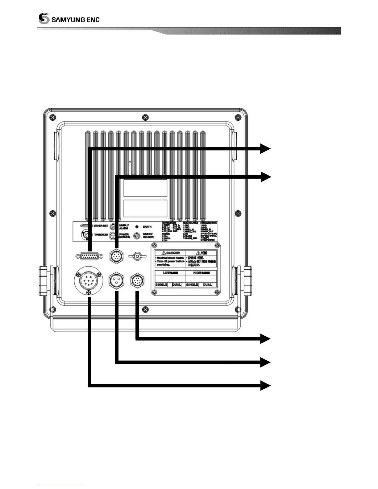
2. Cable connection
Connect power supply and transducer to the proper connector.
ETHER NET
It will be updated
later to use with
SMART SYSTEM via
S-Net
NMEA1 In/Out
(UART1)
External Alarm (It
will be updated
later)
NMEA2 In/Out
(UART2)
Speed sensor input
Temperature sensor
input
Power supply input
10.4 ~ 34VDC
Transducer inpu
Water temperature
sensor input
Page 53
53
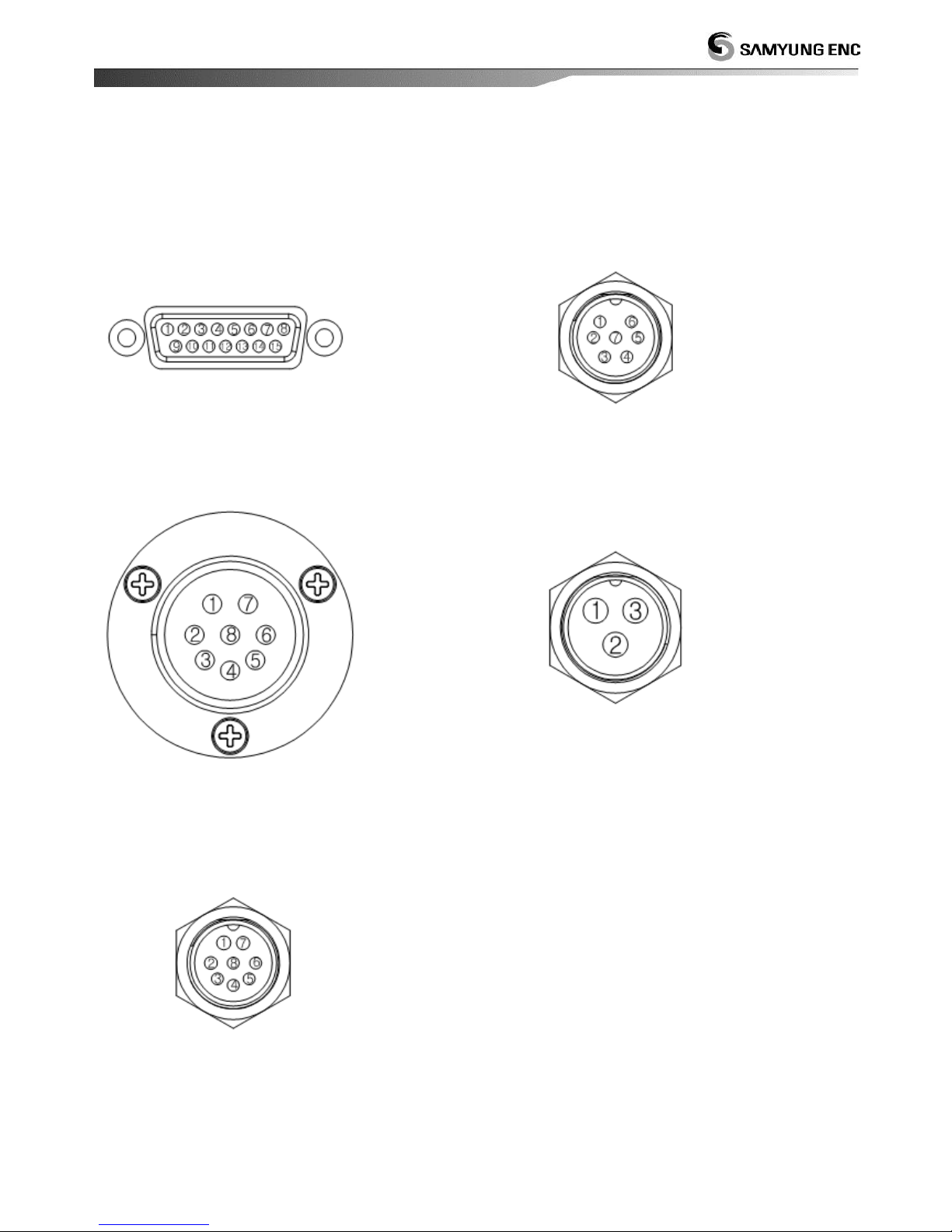
3. Rear connector pinout
Pin position at the back of the transmission indicator.
ETHER NET
NAME1/ALARM
TRANSDUCER
POWER (DC12/24)
NAME2/SENSOR
② COMMON_1
③ TD+
④ GND
⑤ EXT_ON/OFF
⑥ NC
⑦ NC
⑧ NC
⑨ RD-
① GND
② GND
③ NMEA_IN
④ NMEA_OUT
⑤ NC
⑥ ALARM
⑦ ALARM_GND
① TEMP1
② TD_L+
③ TD_H+
④ TD_GND
⑤ TD_L-
⑥ TD_H-
⑦ TEMP2
⑧ NC
① PWR+
② EARTH
③ PWR-
① GND
② GND
③ NMEA_IN
④ NMEA_OUT
⑤ SPEED SUPPLY
⑥ SPEED
⑦ TEMP
⑧ GND
⑩ COMMON_2
⑪ TD-
⑫ GND
⑬ NC
⑭ NC
⑮ NC
Page 54
54
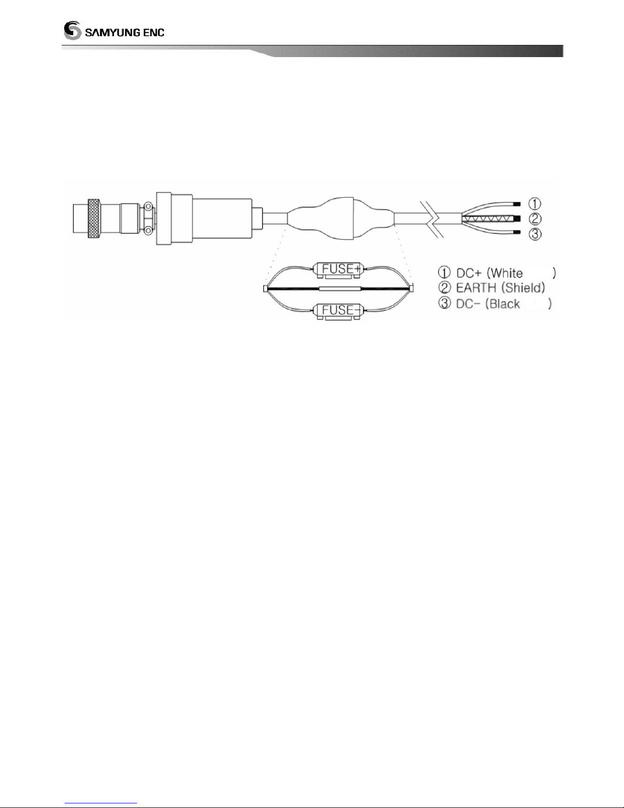
. Connecting power cable
POWER connector on the back of the display is connected to the power cable.
EARTH
① Please use a thick cable of earth
② Please let the ground and earth in a shortest distance
Page 55

55
This section describe the maintenance and trouble-shooting of SDF-310.
System maintenance and repair
Trouble-shooting
6
Maintenance/troubleshooting
Page 56
56
1. System maintenance and repair
Regular maintenance and repair is essential for good performance.
Maintenance of equipment refers to the regular inspection of equipment and the software up-
grade and the following items should be included.
Item
Action
Connector and
terminal
Please check the connector and terminal on the back of the display
for proper connection.
Cable
Check each cable and if the cable is damaged or blown, replace it
immediately.
Earth terminal and
Earth line
Check earth terminal. If the ground terminal is rust of rot, replace or clean state
And check the connection of earth line also.
Maintain cleanliness
Dust or dirt on the LCD can be removed with a tissue or LCD cleaner,
and wipe carefully to prevent scratching. Do not use solvents such as
thinner, acetone or benzene to clean the unit. They can remove paint
and marking.
Page 57
57
2. Troubleshooting
The table describe the symptom of trouble and their trouble-shooting. If the repair isn’t
possible by general remedy, do not attempt to check inside of equipment. If the inspection
and maintenance is wrong, it can degrade the performance of equipment. So all repair works
should be left to AS technician.
A/S Technician ☏ : 1577~0198
Symtom
Remedy
The power does not turnon
Power connector
Power supply and Fuse
Voltage of battery (under DC 12V)
Polarity of the power, + -
Screen is not turned on or
too dark
Screen brightness is 1
Display is night mode
Screen flicker or white lines
Change of screen color
Contact of LCD connector
Cleanness around LCD connector
Fish school isn’t display on
the screen
Poor contact of transducer connector and corrosion
Transducer is under water
Sensitivity is low
If TVG, STC set-up is too high, you can increase the gain
and then decrease TVG, STC.
If the the value of clutter and color erase are too high,
decrease them.
Several seabed
If the depth is too low or sensitivity is too high, you can
control the gain by repeat of sound wave
Low Tx Speed
Record of Fish school and
sea bottom isn’t stable
Because of vessel’s rolling, pitching, bubbles by vessel’s
screw and front vessel can induce them
No oscillation line
Set-up shift ‘0’
Page 58
58
This section describe the appendix related to the equipment operation of SDF-310
Product outline drawing
Appendix
Page 59
59
 Loading...