

Page 1
Page 2

Installation and Operation Manual
2
Page 3

Installation and Operation Manual
3
Industry Canada
Operation is subject to the following two conditions: (1) this device may not cause interference,
and (2) this device must accept any interference, including interference that may cause undesired
operation of the device.
FCC Statement
Note: This equipment has been tested and found to comply with the limits for a Class B digital
device, pursuant to Part 15 of the FCC Rules. These limits are designed to provide reasonable
protection against harmful interference in a normal installation. This equipment generates uses
and can radiate radio frequency energy and, if not installed and used in accordance with the
instructions, may cause harmful interference to radio communications. However, there is no
guarantee that interference will not occur in a particular installation. If this equipment does cause
harmful interference to radio or television reception, which can be determined by turning the
equipment off and on, the user is encouraged to try to correct the interference by one or more of
the following measures:
1- Reorient or relocate the receiving antenna
2- Increase the separation between the equipment and receiver
3- Connect the equipment into an output on a circuit different from that to which the
receiver is connected
4- Consult the dealer or an experienced technician for help
5- A shielded cable must be used when connecting a peripheral to the serial ports
Important
It is the owner‟s sole responsibility to install and use the unit in a manner that will not cause
accidents, personal injury or property damage. The user of this product is solely responsible for
observing safe boating practices.
Global Positioning System: The Global Positioning System (GPS) is operated by the US
government which is solely responsible for its operation, accuracy and maintenance. The GPS
system is subject to changes which could affect the accuracy and performance of all GPS
equipment anywhere in the world.
Installation: If installation is not correct, the unit can not perform at its designed potential. If in
doubt, consult your Samyung ENC dealer. Ensure that any holes made are in a safe position and
will not weaken the boat‟s structure. If in doubt, consult a qualified boat builder.
SAMYUNG ENC DISCLAIMS ALL LIABILITY FOR ANY USE OF THIS PRODUCT IN A WAY THAT MAY
CAUSE ACCIDENTS, DAMAGE OR THAT MAY VIOLATE THE LAW.
Governing language: This statement, any instruction manuals, user guides and other
information relating to the product (documentation) may be translated to, or has been translated
from, another language (translation). In the event of any conflict between any translations of the
documentation, the English language version of the documentation will be the official version of
the documentation. This manual represents the installation procedures as at the time of printing.
Samyung ENC reserves the right to make changes to specifications without notice.
Copyright © 2009 Samyung ENC, Republic of Korea, all rights reserved.
Presentation
Thank you for having purchased a Samyung ENC product. This handbook contains an explanation
of how to install, operate and maintain your unit.
Page 4
Installation and Operation Manual
4
SAFETY INSTRUCTIONS
Electronic charts displayed by the chart plotter are believed to be
accurate and reliable, but they are not intended to replace official
charts which should remain your main reference for all the matters
related to the execution of a safe navigation. For this reason we would like to
remind you that you are required to carry on board and use the officially published
and approved nautical chart.
Please read through this manual before the first operation. If you have any
questions, please contact the customer service or your local dealer or distributor
Extensive exposure to heat may result in damage to the chart plotter.
Connection to the power source with reversed polarity will damage the chart
plotter severely. This damage is not covered by the warranty.
Do not disassemble. The chart plotter contains dangerous high voltage circuits
which only experienced technicians must handle
Exposure of the display to UV rays may shorten the life of the liquid crystals used
in you plotter. This limitation is due to the current technology of the LCD display.
Avoid overheating which may cause loss of contrast and, in extreme case, a
darkening of the screen. Problems which occur from over heating are reversible
when temperature decreases.
Screen Cleaning Precautions
Cleaning your chart plotter screen is a very important operation and must be done
carefully. The following is the cleaning procedure.
You use a tissue or lens tissue and a cleaning spray containing Isopropanol (a
normal spray cleaner sold for PC screens. Fold the tissue or lens tissue into a
triangular shape, moisten the tip and use the index finger behind a corner to
move the tissue across the surface, in overlapping side to side strokes. If the
tissue is too wet, a noticeable wet film will be left in its path and you will need to
repeat the process. If too dry, the tissue won‟t glide easily, and may damage the
surface.
If you require technical advice or assistance, contact your nearest Samyung ENC
office or visit our website, www.samyungenc.com.
Page 5
Installation and Operation Manual
5
1 Introduction
1 Introduction ........................................................................... 5
1-1 General Information ............................................................. 9
1-2 Specification ....................................................................... 9
1-3 Packing List ....................................................................... 12
1-4 Optional Accessories........................................................... 12
2 Getting Started
2-1 Mounting the Unit .............................................................. 13
2-1-1 Bracket Mounting ............................................................................... 13
2-1-2 Flush Mounting .................................................................................. 13
2-2 Keys(Front key , REM-350 Remote) ...................................... 14
2-3 NAVIONICS Secure Digital (SD) Card .................................... 17
2-4 Chart Selection .................................................................. 17
2-5 Simulate Mode .................................................................. 17
2-6 Data Bar ........................................................................... 18
2-7 Compass .......................................................................... 19
2-8 Multi window displays ......................................................... 20
2-9 Man overboard (MOB) ........................................................ 22
3 General Operation
3-1 Manual / Auto Power on and off ........................................... 23
3-2 Brightness, night mode and Background................................ 23
3-3 The page window .............................................................. 24
3-4 Chart .......................................................................... 26
3-4-1 Chart window .................................................................................... 26
3-4-2 Latitude and longitude ........................................................................ 27
3-4-3 Chart scale ........................................................................................ 27
3-4-4 Finding a chart symbol ....................................................................... 27
3-4-5 S-Map search .................................................................................... 28
3-4-6 Chart symbols and information ............................................................ 28
3-4-7 Introduction to navigating ................................................................... 28
3-4-8 Going to a waypoint or to a point on the chart ...................................... 29
3-4-9 Following a route ............................................................................... 29
3-4-10 Goto Key ......................................................................................... 29
3-4-11 Distance and bearing calculator ......................................................... 30
3-4-12 Projected course .............................................................................. 30
3-4-13 Finding a Char Symbol ...................................................................... 30
3-4-14 Tracks Settings in the Chart window ................................................... 31
3-5 Sonar ......................................................................... 32
3-5-1 Interpreting the display ...................................................................... 32
3-5-2 Mode ................................................................................................ 32
3-5-3 Single and Dual frequency fish finding ................................................. 33
3-5-4 Range ............................................................................................... 33
3-5-5 Gain ................................................................................................. 34
Page 6
Installation and Operation Manual
6
3-5-6 Sonar window display ......................................................................... 35
3-5-7 No split ............................................................................................. 35
3-5-8 Split zoom and Full Screen zoom ......................................................... 36
3-5-9 Split bottom ...................................................................................... 36
3-5-10 Split 50/200 ..................................................................................... 37
3-5-11 Split A-Scope ................................................................................... 37
3-6 Highway ..................................................................... 38
3-7 Gauges....................................................................... 38
3-8 Waypoints .................................................................. 39
3-8-1 Creating a new waypoint .................................................................... 39
3-8-2 Moving a waypoint ............................................................................. 39
3-8-3 Editing an existing waypoint ................................................................ 39
3-8-4 Deleting a waypoint ........................................................................... 40
3-8-5 Find a waypoint ................................................................................. 40
3-8-6 Sort Waypoints .................................................................................. 40
3-8-7 Deleting all waypoints ........................................................................ 40
3-9 Routes ....................................................................... 41
3-9-1 Managing a route from the chart window ............................................. 41
3-9-2 Managing a route from the route window ............................................. 42
3-10 Satellites ................................................................... 43
3-10-1 Satellite information ......................................................................... 43
3-11 Tides ........................................................................ 44
3-12 AIS .......................................................................... 45
3-12-1 Viewing AIS Vessels .......................................................................... 45
3-12-2 AIS Windows ................................................................................... 45
3-13 DSC ......................................................................... 47
3-13-1 distress ........................................................................................... 47
3-13-2 Poll ................................................................................................. 48
3-14 NAVTEX .................................................................... 49
3-15 Engine Faults ............................................................. 49
4 Advance Settings
4-1 System Configuration Settings ....................................... 50
4-1-1 Language .......................................................................................... 50
4-1-2 Chart Selection .................................................................................. 50
4-1-3 Beep volume ..................................................................................... 50
4-1-4 Auto power ....................................................................................... 50
4-1-5 Features............................................................................................ 50
4-1-6 Factory reset ..................................................................................... 50
4-1-7 About ............................................................................................... 50
4-2 Chart Settings.............................................................. 51
4-2-1 Rotation ............................................................................................ 51
4-2-2 Palette .............................................................................................. 51
4-2-3-1 General(NAVIONICS) ....................................................................... 51
4-2-3-2 General(S-MAP) .............................................................................. 52
4-2-4-1 Land & Sea (NAVIONICS) ................................................................ 52
4-2-4-2 Land & Sea (S-MAP) ........................................................................ 52
Page 7
Installation and Operation Manual
7
4-2-5 Map datum ........................................................................................ 52
4-2-6 NMEA datum offset ............................................................................ 53
4-2-7 Map shift ........................................................................................... 53
4-2-8 Restore default .................................................................................. 53
4-3 Sonnar Settings ........................................................... 54
4-3-1 Frequency ......................................................................................... 54
4-3-2 Palette .............................................................................................. 54
4-3-3 Scroll speed ....................................................................................... 54
4-3-4 Digit size ........................................................................................... 54
4-3-5 Fish .................................................................................................. 54
4-3-6 Advance Settings ............................................................................... 54
4-3-7 Restore default .................................................................................. 54
4-4 GPS Settings ............................................................... 55
4-4-1 GPS Source ....................................................................................... 55
4-4-2 DGPS Source ..................................................................................... 55
4-4-3 Static Navigation ................................................................................ 55
4-4-4 Speed Filter and Course Filter.............................................................. 55
4-4-5 Lat/Lon d.p‟s ..................................................................................... 55
4-4-6 Ship speed ........................................................................................ 55
4-4-7 Magnetic Variation ............................................................................. 55
4-5 Track & Log Settings .................................................... 56
4-5-1 Track ................................................................................................ 56
4-5-2 Logs ................................................................................................. 56
4-6 Memory Settings .......................................................... 57
4-6-1 Save ................................................................................................. 57
4-6-2 Load ................................................................................................. 57
4-6-3 Delete ............................................................................................... 57
4-6-4 Format .............................................................................................. 58
4-6-5 Screen snap shot ............................................................................... 58
4-7 AIS Settings ................................................................ 58
4-7-1 Display filter ...................................................................................... 59
4-7-2 Alarm option...................................................................................... 59
4-7-3 Display options .................................................................................. 59
4-7-4 Restore default .................................................................................. 59
4-8 Alarms ....................................................................... 60
4-8-1 Fish .................................................................................................. 60
4-8-2 Deep ................................................................................................ 60
4-8-3 Shallow ............................................................................................. 60
4-8-4 Temperature ...................................................................................... 60
4-8-5 Temperature rate ............................................................................... 60
4-8-6 Low battery ....................................................................................... 60
4-8-7 Navigation alarms .............................................................................. 60
4-8-8 AIS ................................................................................................... 60
4-8-9 DGPS ................................................................................................ 60
4-8-10 Restore default ................................................................................ 60
4-9 Others ........................................................................ 61
4-9-2 Waypoint .......................................................................................... 61
4-9-3 GPS .................................................................................................. 61
4-9-4 Units................................................................................................. 61
4-9-5 Comms ............................................................................................. 61
4-9-6 Calibrate ........................................................................................... 61
4-9-7 Time ................................................................................................. 61
Page 8

Installation and Operation Manual
8
4-9-8 Restore default .................................................................................. 61
4-9-9 Calendar ........................................................................................... 61
5 INSTALLATION
5-1 Options and Accessories ..................................................... 62
5-2 Connections ...................................................................... 63
5-3 Power/data cable ............................................................... 63
5-4 GPS antenna ..................................................................... 64
5-4-1 antenna ............................................................................................ 64
5-4-2 The antenna using NMEA .................................................................... 64
5-5 NMEA 0183 ....................................................................... 65
5-6 NMEA 2000 ....................................................................... 66
5-7 Sonar Transducers ............................................................. 67
5-8 Setup and test ................................................................... 68
Page 9

Installation and Operation Manual
9
1-1 General Information
The chart plotter is a precision-crafted GPS
chart Plotter with high-performance receiver
for the Global Positioning System
constellation of satellites, providing precise
location data with a host of navigation
features. Some functions require optional
units and sensors installed on your boat.
The chart plotter can be connected to
external devices with NMEA0183 and
NMEA2000 interface and display information.
Following are the examples.
• NAVTEX
• AIS receiver
• DSC VHF radio
• Transducer & sensors
• Autopilot
1-2 Specification
1 Introduction
Page 10
Installation and Operation Manual
10
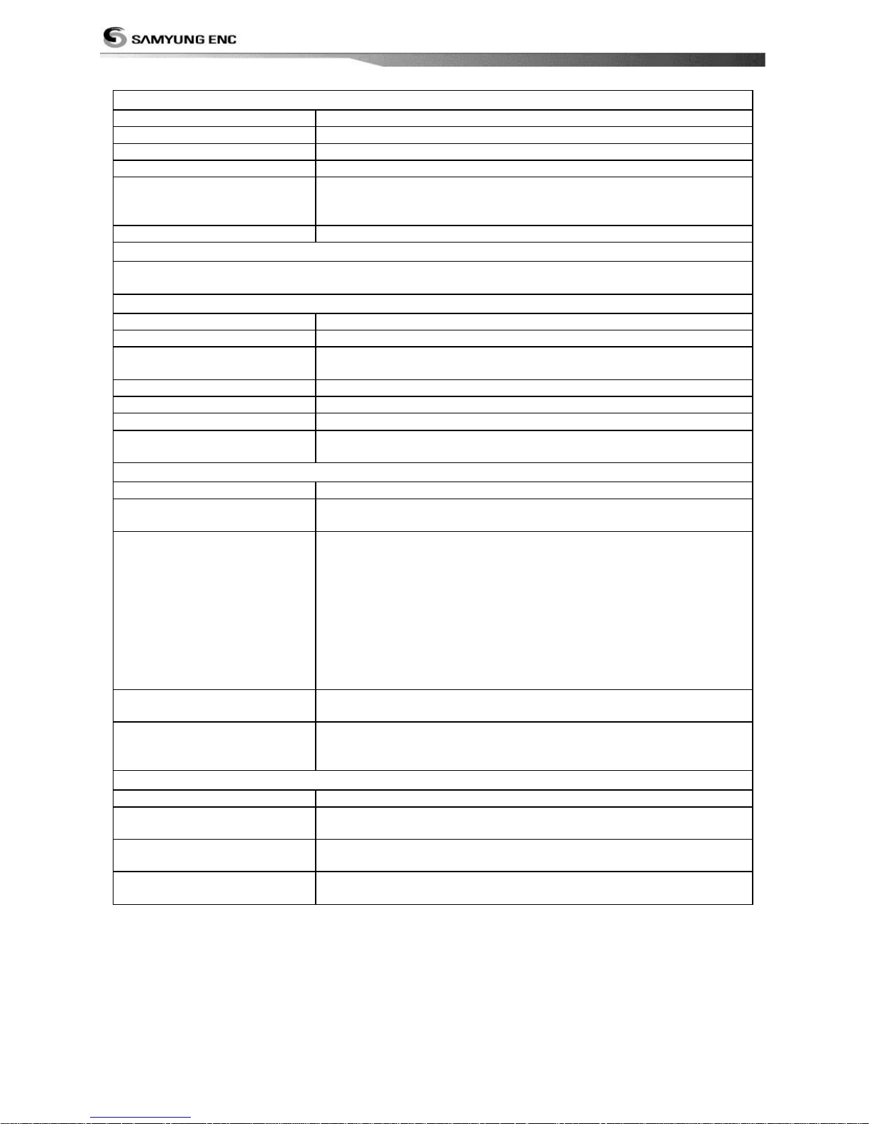
[NF700][N700]
GENERAL
Category
Detail
Size
205 mm(W) x 171 mm(H) x 75 mm(D)
Display
7” diagonal, TFT color, 800 x 480 pixels.
Supply voltage
10 to 32 V DC
Supply current
13.8 V
400 mA min - no backlighting.
600 mA max - full backlighting.
Operating temperature
-10° to 50°C
ALARMS
User set: Arrival radius, anchor, XTE, danger, too shallow, too deep, fish, temperature, temperature rate,
low battery, loss of DGPS fix, dangerous AIS vessels.
GPS NAVIGATION
Chart card
NAVIONICS SD Card
User card
SD Card
Waypoints
Up to 10,000, with default or user defined alphanumeric names up to
eight characters.
Routes
100 Routes, with up to 100 points each
Tracks
By time or distance, 10 track of 15,000 points
Chart datums
216 Chart datums, One user-defined map shift.
Chart scale
0.2 to 500 nm for chart (chart dependent) down to 0.005 nm in plotter
mode.
COMMUNICATIONS
NMEA
NMEA 0183 4800, 9600, 38400 baud, NMEA 2000
NMEA 0183 Inputs from
compatible instruments
DBK, DBS, DBT, DPT, GGA, GLL, GNS, GGA, GSV, HDG, HDT, MDA,
MTA, MTW, MWD, MWV, RMC, RPM, VHW, VTG, VWT, ZDA
NMEA 2000 Inputs from
compatible instruments
System date and time(PGN126992),Vessel
Heading(PGN127250),Engine parameters/Rapid Update(PGN127488),
Engine parameters/Dynamic(PGN127489),Trip
parameters/Engine(PGN127497),Engine
parameters/Static(PGN127498),Fluid level(PGN127505),Water
Speed(PGN128259),Water depth(PGN128267),Position/Rapid
Update(PGN129025),COG & SOG/Rapid Update(PGN129026),GNSS
Position Data(PGN129029),GNSS DOPs(PGN129539),GNSS Sats in
View(PGN129540),Wind Data(PGN130306),Environmental ParameterWater temp(PGN130310),Environmental Parameter(PGN130311)
NMEA 0183 Outputs, for
compatible instruments
APA, APB, BWR, GGA, GLL, GSA, GSV, RMB, RMC, VTG, XTE, DBT,
DPT, MTW, VHW, XDR
NMEA 2000 Outputs, for
compatible instruments
Water Speed(128259), Water depth(128267), XTE(129283), NAV.
data(129284), NAV. data(129285), COG & SOG(129026), GNSS
position(129029), Water temp.(130310)
SONAR FISHFINDING [N700] doesn’t have below function
Depth range
0 m to 600 m
Sonar output
Power: Variable, up to 600 W RMS
Dual frequency: 50 khz and 200 kHz
Temperature
Range 0° to 37.7°C (32°F to 99.9°F)
Resolution of 0.1° unit.
Speed (from paddlewheel
transducer)
1 to 96.6 kph (57.5 mph, 50 kn).
Page 11

Installation and Operation Manual
11
[F700]
GENERAL
Category
Detail
Size
205 mm(W) x 171 mm(H) x 75 mm(D)
Display
7” diagonal, TFT color, 800 x 480 pixels.
Supply voltage
10 to 34 V DC
Supply current
13.8 V
400 mA min - no backlighting.
600 mA max - full backlighting.
Operating temperature
-10° to 50°C
ALARMS
User set: Arrival radius, anchor, XTE, danger, too shallow, too deep, fish, temperature, temperature rate,
low battery, loss of DGPS fix, dangerous AIS vessels.
COMMUNICATIONS
NMEA
NMEA 0183 4800, 9600, 38400 baud, NMEA 2000
NMEA 0183 Inputs from
compatible instruments
DBK, DBS, DBT, DPT, GGA, GLL, GNS, GGA, GSV, HDG, HDT, MDA,
MTA, MTW, MWD, MWV, RMC, RPM, VHW, VTG, VWT, ZDA
NMEA 2000 Inputs from
compatible instruments
System date and time(PGN126992),Vessel
Heading(PGN127250),Engine parameters/Rapid Update(PGN127488),
Engine parameters/Dynamic(PGN127489),Trip
parameters/Engine(PGN127497),Engine
parameters/Static(PGN127498),Fluid level(PGN127505),Water
Speed(PGN128259),Water depth(PGN128267),Position/Rapid
Update(PGN129025),COG & SOG/Rapid Update(PGN129026),GNSS
Position Data(PGN129029),GNSS DOPs(PGN129539),GNSS Sats in
View(PGN129540),Wind Data(PGN130306),Environmental ParameterWater temp(PGN130310),Environmental Parameter(PGN130311)
NMEA 0183 Outputs, for
compatible instruments
DBT, DPT, MTW, VHW, XDR
NMEA 2000 Outputs, for
compatible instruments
Water Speed(128259), Water depth(128267), Water temp.(130310)
SONAR FISHFINDING
Depth range
0 m to 600 m
Sonar output
Power: Variable, up to 600 W RMS
Dual frequency: 50 khz and 200 kHz
Temperature
Range 0° to 37.7°C (32°F to 99.9°F)
Resolution of 0.1° unit.
Speed (from paddlewheel
transducer)
1 to 96.6 kph (57.5 mph, 50 kn).
Page 12
Installation and Operation Manual
12
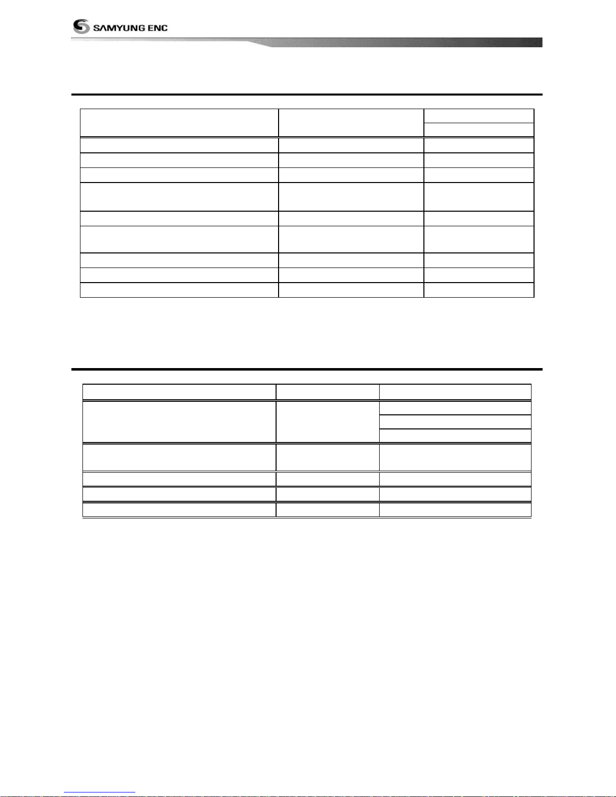
1-3 Packing List
Item List
Part
number
Model
N700,F700, NF700
Display
N700-E
Ο Ο Ο
Bracket
N700-DB
Ο Ο Ο
Display Cover
N700-CC
Ο Ο Ο
Power Cable
LTW-1750-8
LTW-2000-8
Ο Ο Ο
Bracket mounting screw
N700-BP
Ο Ο Ο
GPS Antenna +
GPS Antenna Support
SAN-60-10M
Ο X Ο
Protection Cover
N700-CB
Ο Ο Ο
User’s Manual(Eng)
N700-ME
Ο Ο Ο
B45 Transducer
B45
X Ο Ο
1-4 Optional Accessories
Model
Part number
Item List
GPS Antenna +
GPS Antenna Support
SAN-60-20M
GPS antenna + BNC Plug
GPS antenna support
GPS antenna cable(10m)
GPS Antenna Stand type
Support
57745
GPS Antenna Stand type
Support
Y cable
NF700-YC
Y cable(see section 5-8)
P58 Transducer
P58
Option
P39 Transducer(NMEA 2000)
P39
Option(for only N700)
Page 13
Installation and Operation Manual
13
2-1 Mounting the Unit
The chart plotter is supplied with bracket and flush mounting kit. You can choose a method of
installation according to your preference.
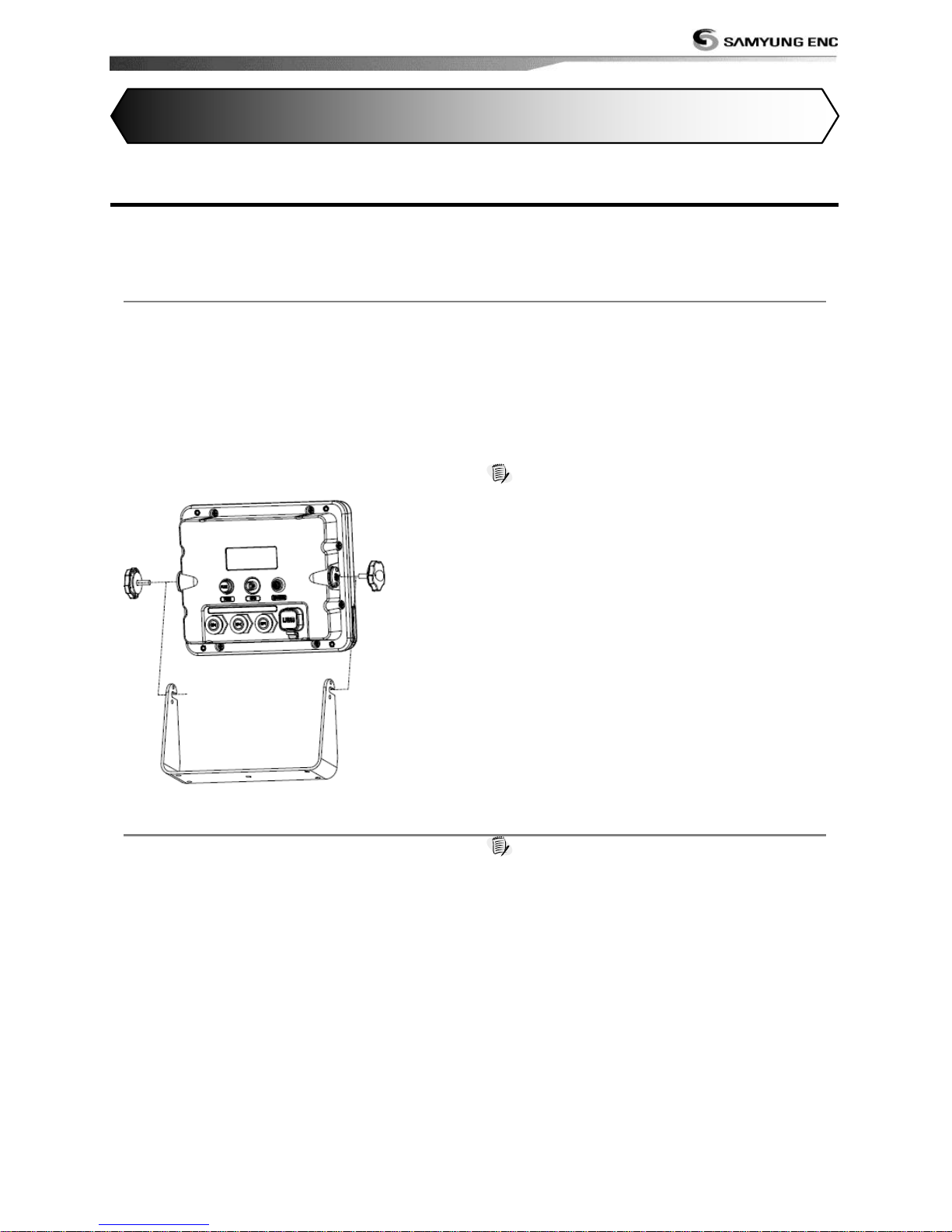
2-1-1 Bracket Mounting
Before installing ensure the area the bracket is mounted to is strong enough to support the
weight of the GPS chart plotter. After the location is found, attach the mounting base to the
area using the supplied hardware.
Mounting the display Unit:
1 Hold the display unit and find a groove
joint between the display unit and bracket.
2 Gently push the display unit into the
groove of bracket and turn the knob to
clockwise to lock
Removing the display unit:
1 Turn the unit off
2 Turn the knob to counter clockwise
3 Pull the display unit out.
Note
The chart plotter with internal GPS antenna is
designed to be bracket mounting and flush mounting.
However, if you flush mount inside of your boat, GPS
performance can be reduced.
2-1-2 Flush Mounting
1 Find a location for flush mounting.
2 Drill a hole in the area of the cutout area
for the blade of jig saw.
3 insert and cut out the area on the panel
using the jig saw
4 Drill four holes for mounting studs.
5 Install the mounting studs on the chart
plotter and insert them into the mounting
hole.
6 Attach the chart plotter to the mounting
location by attaching the supplied
hardware to the mounting studs.
Note
1 If you flush mount, you need the optional external
GPS antenna.
2 Before Drilling holes make sure there is enough
space to mount the chart plotter there is no
obstructions.
2 Getting Started
Page 14
Installation and Operation Manual
14
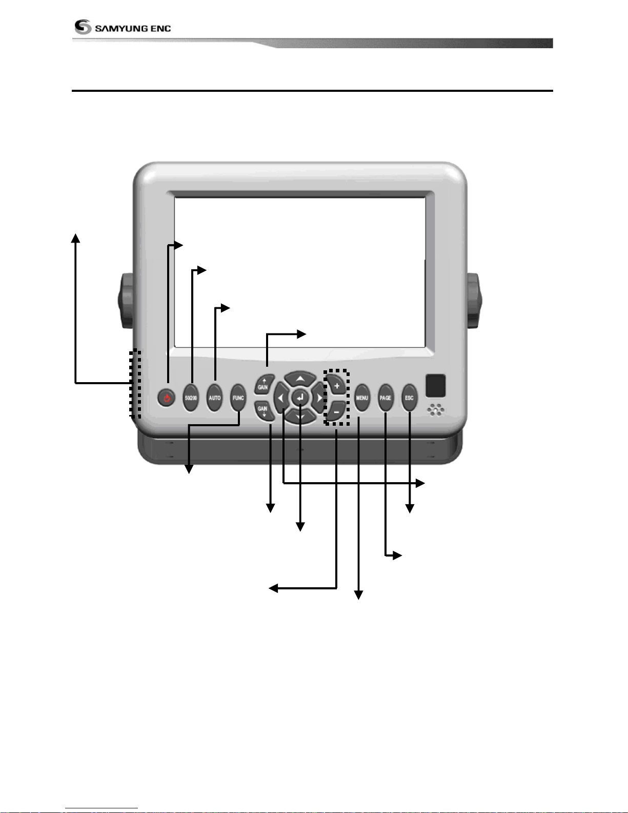
2-2 Keys
[F700]
Power Button
Tunrs Power On/Off
50/200 Button
Set a Freq. At 50, 200 for Sonar
Auto Button
Set an Auto mode during Sonar on
Func. Button
Save a screen
(Menu for tracks will be displayed when push this button long.)
Sensitivity (+) Button
Set a sensitivity for Sonar on(+)
4ways Button
Move Map and cursor in 4
wyas
Move Menu curson
Sensitivity (-) Button
Set a sensitivity for Sonar on (-)
Enter Button
Select Menu, Input Data and confirm data
(Menu for selecting Mark will be displayed when push this button long at the map
screen)
ESC Button
Go back to Plotter from
Menu, cancel Input mode
Display Button
Select a screen what users want
Menu Button
Show/Delete Menu
Go back to Prev. Menu
Zoom in Button
Zoom in a screen
Zoom out Button
Zoom out a screen
SD Card Slot
Save/Load user’s data
Page 15
Installation and Operation Manual
15
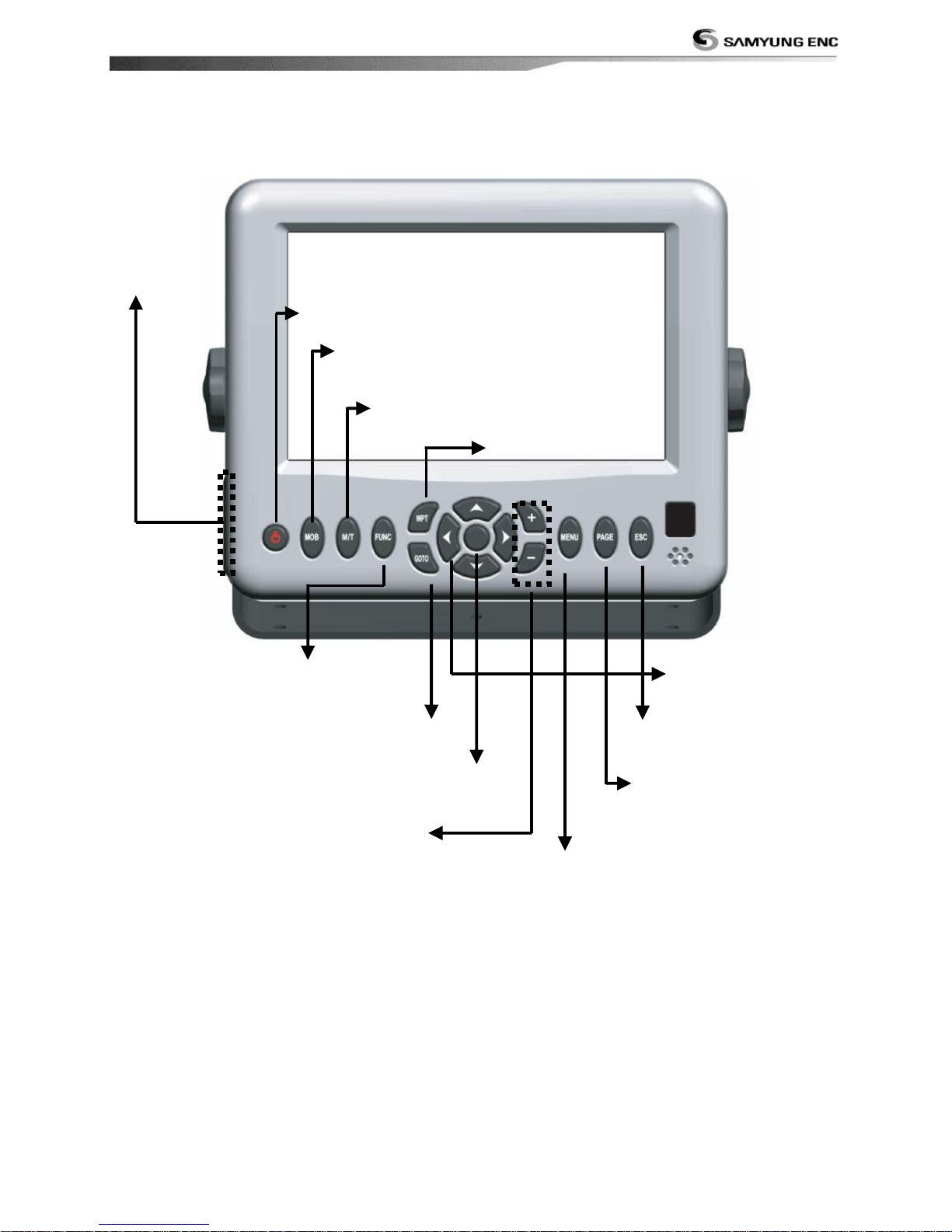
[NF700][N700]
Power Button
Tunrs Power On/Off
MOB Button
Display MOB destination on a location of
the boat
M/T Button
WPT Button
Set a way point on the map
4ways Button
Move Map and cursor in 4
wyas
Move Menu curson
GOTO Button
Start Navigating to MOB destination
ESC Button
Go back to Plotter from
Menu, cancel Input mode
Display Button
Select a screen what users want
Menu Button
Show/Delete Menu
Go back to Prev. Menu
Zoom in Button
Zoom in a screen
Zoom out Button
Zoom out a screen
SD Card Slot
Save/Load user’s data
Func. Button
Save a screen
(Menu for tracks will be displayed when push this button long.)
Enter Button
Select Menu, Input Data and confirm data
(Menu for selecting Mark will be displayed when push this button long at the map screen)
Page 16
Installation and Operation Manual
16
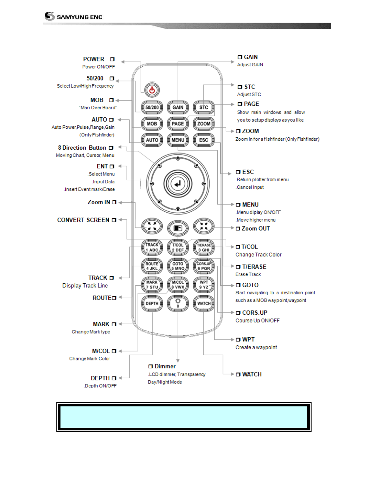
[REM-350]
※ Remote control(REM-350) is Option device
Page 17
Installation and Operation Manual
17
2-3 NAVIONICS Secure Digital (SD) Card
This section provides instructions for inserting and removing NAVIONICS SD card procedure.
Inserting the SD Card
1 Grab a card before inserting as
NAIONICS label heading down
2 Open the door, gently push the SD card
into the slot; push the SD card in as far as
you hear click sound, then close door.
Removing the SD Card
1 Turn off the unit.
2 Open the door and push in on the SD card
until it is released.
3 Close the door.
Insert NAVIONICS SD card
correctly.
(DO NOT FORCE)
Close SD card door firmly all
the times.
Do not remove SD card
during reading and writing.
2-4 Chart Selection
A user can select a map between NAVIONICS
and S-MAP.
Chart Selection
1 Press and hold .
2 Select the system setting icon.
3 Select Chart then a chart you prefer.
S-MAP is a preinstalled chart but
optional NAVIONICS
can be used. Please
contact your nearest
Samyung ENC office
for purchasing the
NAVIONICS.
2-5 Simulate Mode
Simulate Mode is great for practicing the actual use of a product when the satellites signals
and internal alarms are not available. In the simulate mode, the unit turns the GPS receiver off
and ignores data from all optional devices.
Two simulate modes are available as below.
• Normal: Allows a user to practicing the
actual use of a product without satellites
connection.
• Demo: boat travel alone given route at
given speed and show different function of
the unit.
Do not try to navigate in a
simulate mode. While the
simulate mode is turned on,
the GPS receiver is not
active.
Page 18
Installation and Operation Manual
18
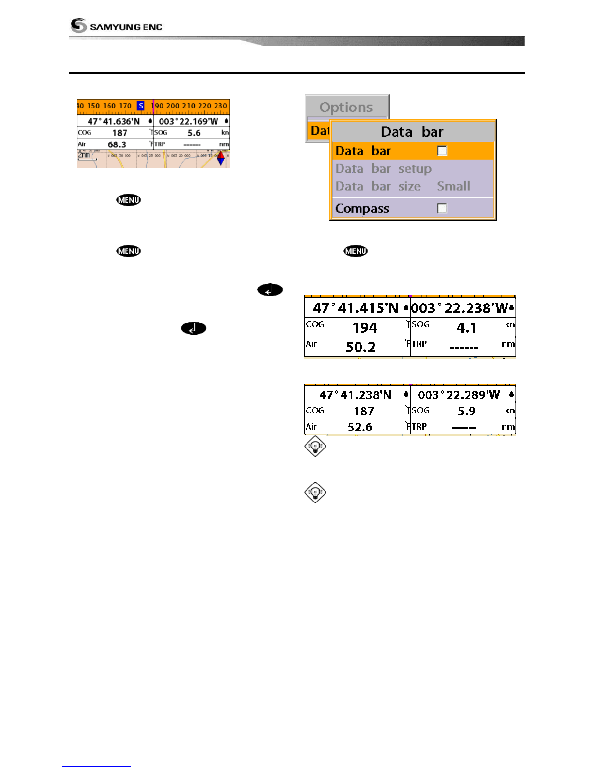
2-6 Data Bar
Data bar displays useful navigation
information at the top of the display.
Displaying Data bar
1 Press and select Data bar.
2 Select Data bar.
Setting the data displayed in data bar
1 Press and select Data bar.
2 Select Data bar then Data bar setup.
3 Move the cursor key to highlight the data
field you want to change then press .
4 Select Data type.
5 Select a desired data you want to display in
the field then press .
6 Repeat above steps if necessary.
Selecting the Data bar size
1 Press and select Data bar.
2 Select Data bar then Data bar size.
3 Select the desired size of data bar.
[Large]
[Small]
Tip: If you select None for all data fields,
the data bar will disappear to save space for
the chart.
Tip: Even though you setup a data bar
for specific window, the data bar is not apply
to all other window.
Page 19
Installation and Operation Manual
19
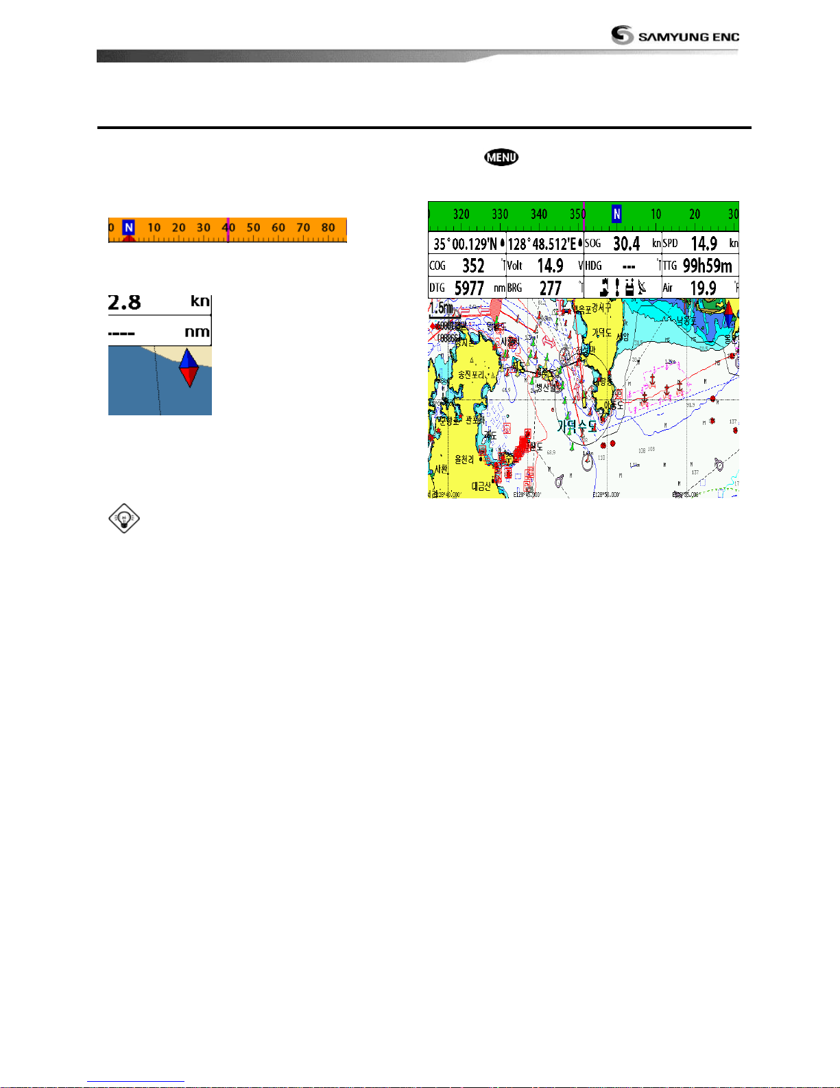
2-7 Compass
The chart plotter computes compass direction
from the constellation of GPS satellites. For
the GPS chart plotter to compute direction
the vessel must be moving through the
water.
For easy reading and recognition, there is a
compass needle at top right side.
When the compass is displayed, COG is
always displayed in data field.
Also when you are navigating to a point, COG
and BRG is always displayed in data bar.
Tip
COG(Course Over Ground) – The course you
vessel is heading.
BRG(Bearing) – The direction from your
current position to a destination point.
To turn the compass off or on:
1 Press and select Data bar.
2 Select Compass.
Page 20
Installation and Operation Manual
20
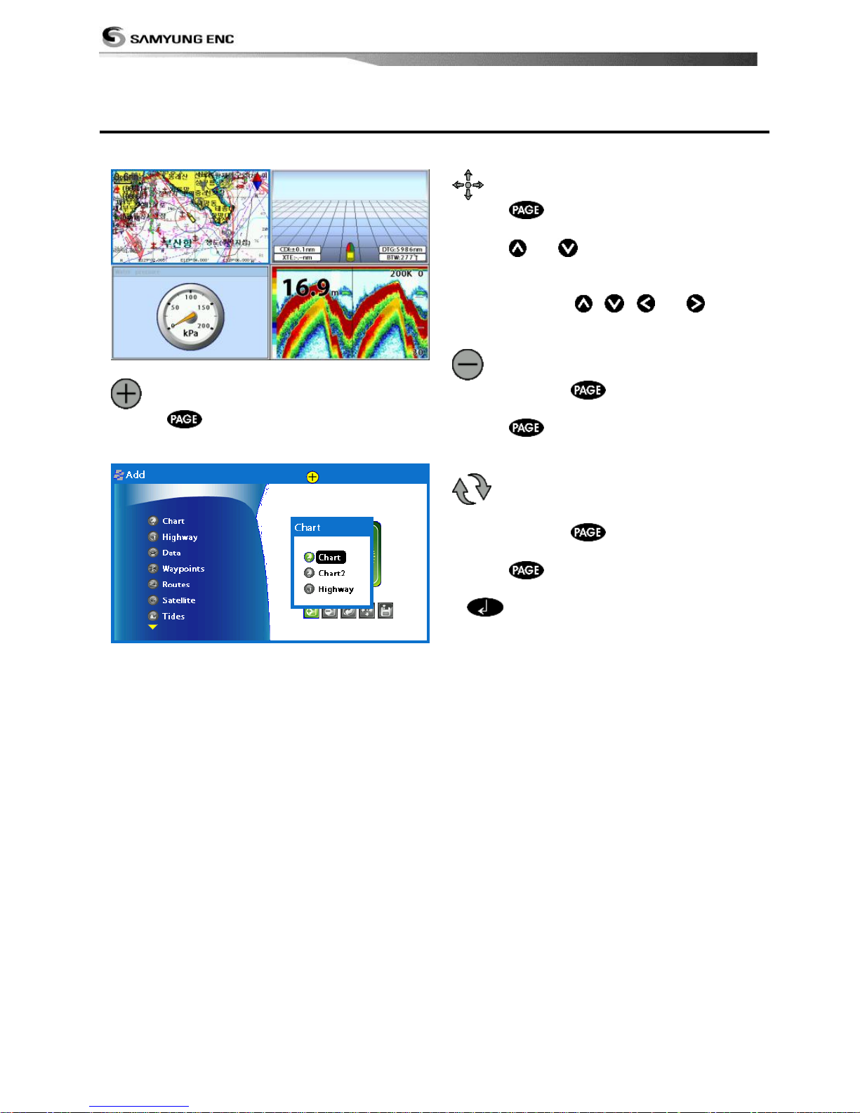
2-8 Multi window displays
The Chart plotter can display up to four
windows at the same time.
Adding a window
1 Press and select Add icon.
2 Select an icon you want to add.
3 Repeat above steps if necessary.
Changing window size
1 Press and select Split icon on
bottom.
2 Press
or to change the height of
the windows if there is only two windows.
If the unit is displaying more that three
windows, press , ,
or
to
change the height of the windows.
Deleting a window
1 Press and hold
to select a window
you want to delete.
2 Press and select Remove icon to
remove.
Replacing two windows on the
display
1 Press and hold to active desired
window you want to replace.
2 Press , select Replace icon.
3 Select icon you want to display then press
.
Page 21
Installation and Operation Manual
21
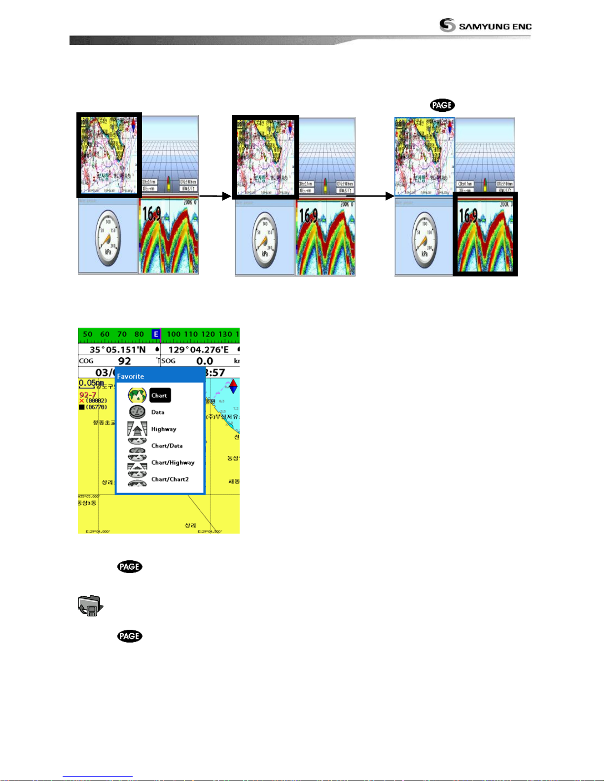
The active window
To distinguish an active window among windows, an orange border indicates the active
window. To change the active window to the next window, press and hold .
Favorite displays
The most commonly used windows are called favorite displays and up to six favorite windows
can be saved. Also each favorite display can have data bar and compass.
Displaying a favorite display
1 Press twice.
2 when above window pops up select a desire display you want.
Adding a favorite display
1 Organize a window as you want.
2 Press to show the main window.
3 Select Save icon at the bottom
4 Select an icon where you want to add your favorite display. If you add the new favorite
display on existing favorite display new display will overwrite the old display.
Page 22
Installation and Operation Manual
22
2-9 Man overboard (MOB)
During navigation, the “MOB” feature
provides a one-touch method of storing a
location, such as point where a crew member
fell overboard. In this mode, the chart plotter
places a MOB point on the chart page and all
the navigation data shown is related to
navigating back to this point, allowing you to
retrace your path to the MOB point
efficiently.
MOB will not work if the
unit does not have a GPS
fix.
1 When you press , a MOB waypoint is
created.
2 When
is pushed not in the Chart
window, the screen automatically is
changed to Chart window and MOB
waypoint is at the center of the chart.
3 If autopilot is connected, the unit sets the
MOB waypoint to be the destination and
start to navigate.
This might result in a
sudden and dangerous turn.
Tip: Even though navigation to MOB
waypoint is canceled, the MOB waypoint is
not be removed from the waypoint list. To
delete the MOB waypoint, you need to delete
it manually.
MOB is saved in Waypoint window of Main
screen. Please refer p39 for how to delete.
Page 23
Installation and Operation Manual
23
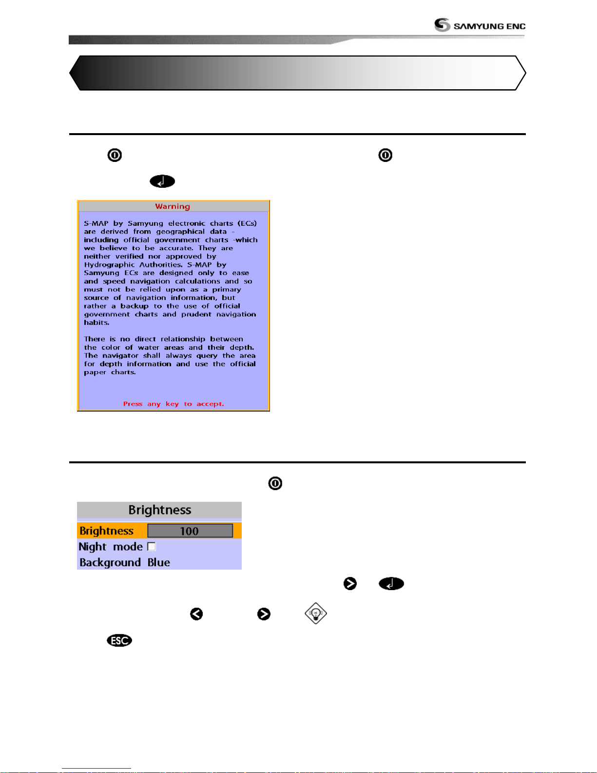
3-1 Manual / Auto Power on and off
Manual power on
Press
and hold until the display shows
the start up page. When the Warning screen
appears, press to accept.
Manual power off
Press and hold for 5 seconds. A counter
timer appears on the screen, if you release
the button before the countdown timer
reaches zero, the chart plotter will remain On.
Auto power
If the unit is wired for auto then:
• The unit turns on automatically when you
turn on the boat‟s ignition.
• You can not turn off the unit if the ignition
is turned on.
• If Auto power off is set, the unit turns off
automatically when you turn off the boat‟s
ignition.
• If Auto power off is set, the unit will not be
turned off even though the boat‟s ignition is
turned off. To turn off, you need to turn off
the unit manually.
3-2 Brightness, night mode and Background
You can change the screen setting for the
display. To change settings, shortly press .
Brightness
To change the brightness, select
Brightness, and press
to dim or to
brighten.
Press
to return to the previous
screen.
Night mode
The chart plotter has preprogrammed
settings allowing you to customize the look of
the Chart window. The default is daytime
view. Select Night mood depending on what
mode the display is in at the time of
selection.
To change mode:
1 Highlight Night mode.
2 Press
or .
Tip: The screen will be difficult to read if
the chart plotter is in night mood when the
sun is too bright
Background
You can Changes the background color if
necessary. This selection is a personal
preference. Select the option that gives you
the clearest viewing in your weather
conditions and viewing angle.
3 General Operation
Page 24
Installation and Operation Manual
24
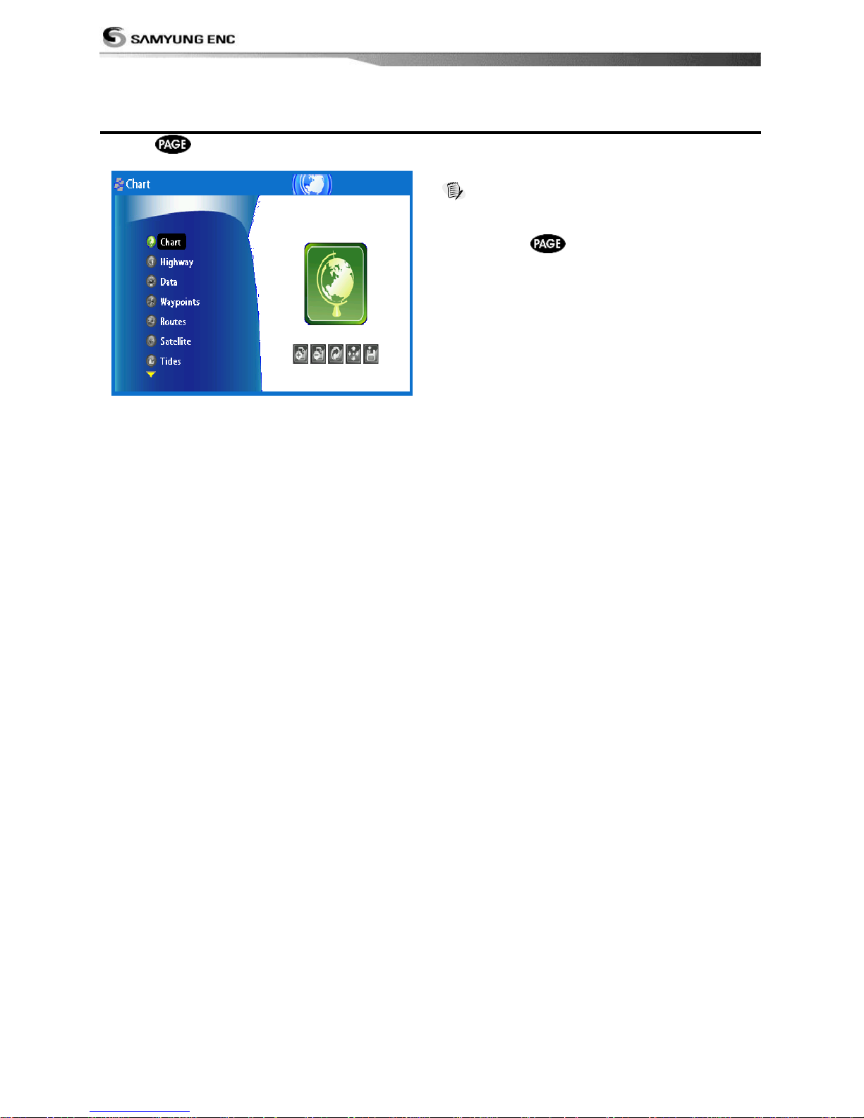
3-3 The page window
Press
to show the page window and select a function icon you want to display.
Note
1 Some function icons require optional units and
connected sensors.
2 If you press
one more time in the main
window, favorite window is displayed.
NF700 (N700 has no sonar function.)
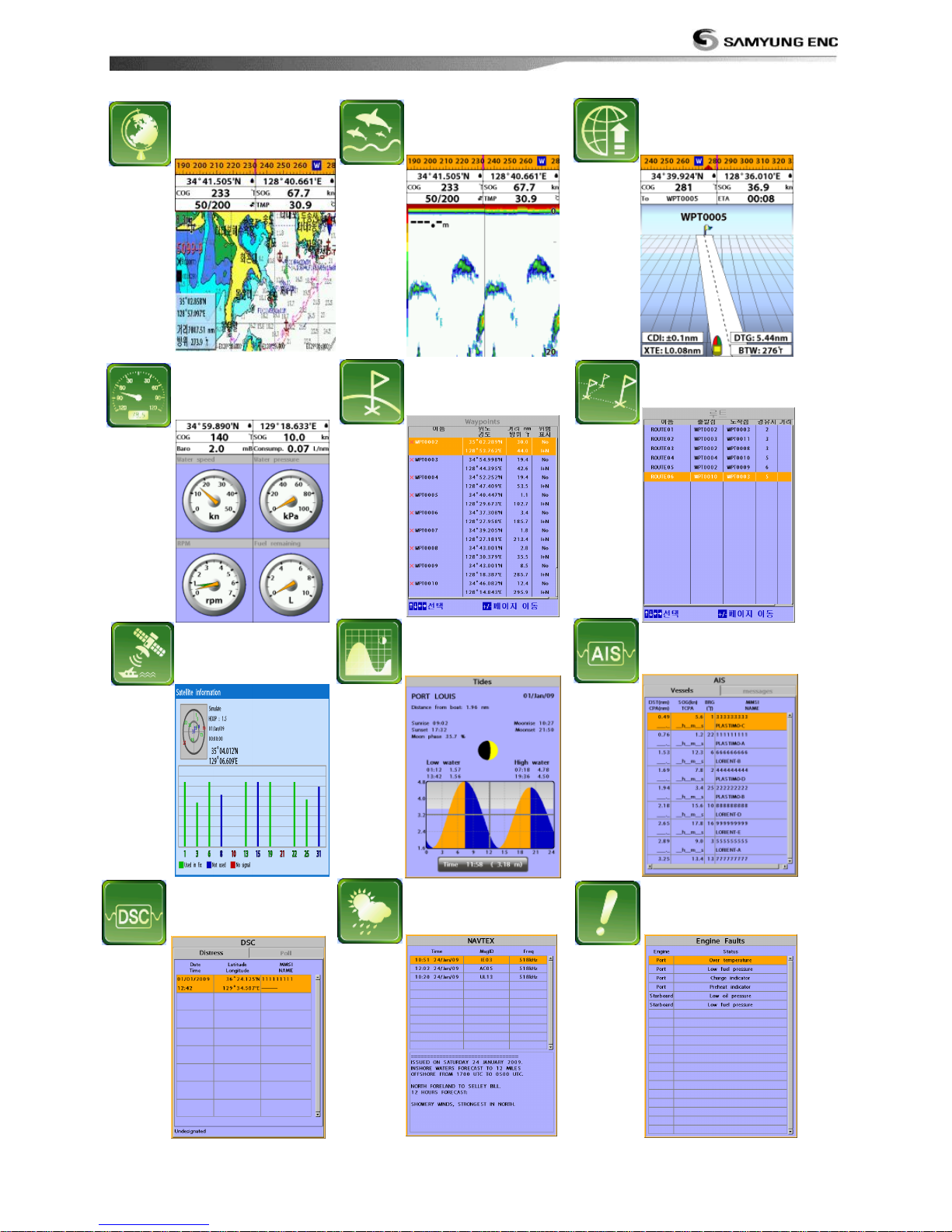
Page 25
Installation and Operation Manual
25
Routes
Data
Waypoints
AIS
Tides
DSC
Navtex
Engine Faults
Sonar
Highway
Chart
Satellites
Page 26
Installation and Operation Manual
26
3-4 Chart
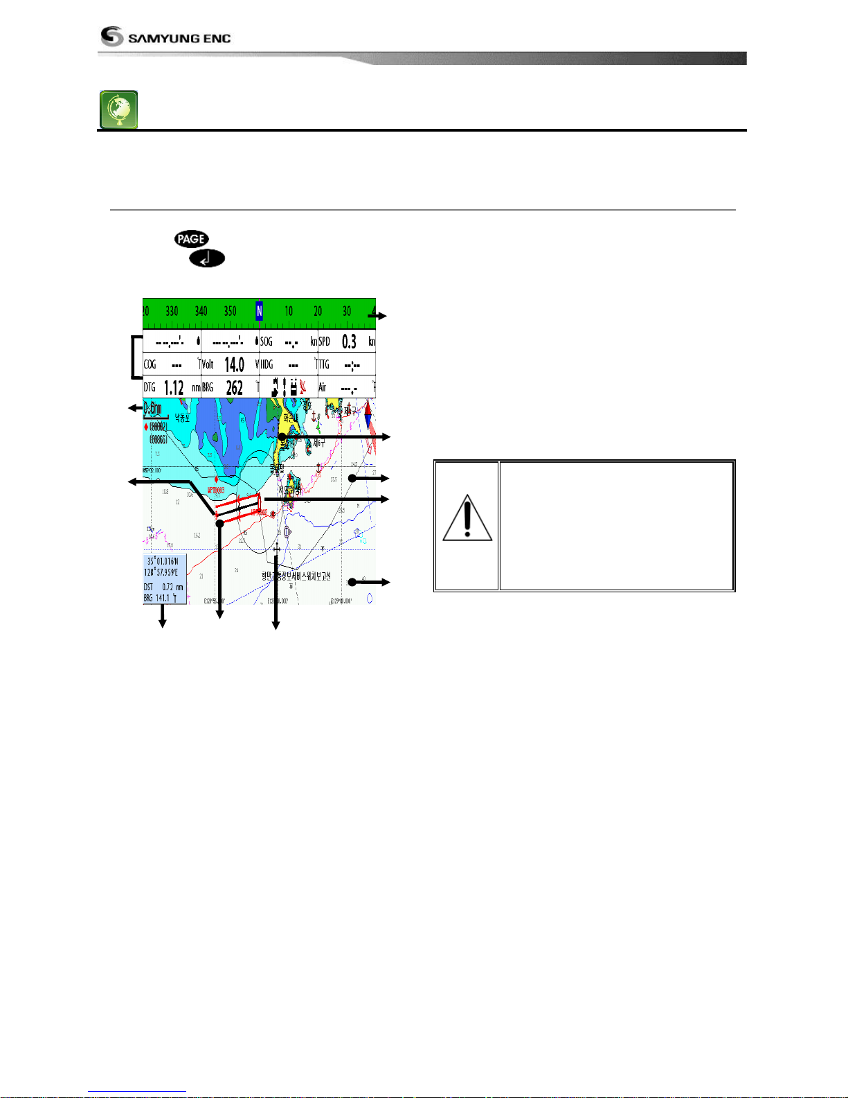
The Chart window mainly shows all relevant navigation data available on your preloaded maps,
including buoys, lights, cables, depth soundings, marinas, and tide station in an overhead view.
3-4-1 Chart window
To go to the Chart window:
• Press and select Chart icon by
pressing .
A typical Chart window shows:
① Data bar. To turn the data off or on or to
change what data is displayed
② Compass
③ Chart scale
④ Boat position
⑤ Boat track
⑥ Boat course and CDI lines
⑦ Distance and bearing of cursor from boat
⑧ Land
⑨ Sea
⑩ The cursor
⑪ A typical waypoint
The built-in world chart
does not show enough
detail for navigation. When
you use the Chart Plotter to
navigate, always use a chart
card which covers the
region.(NAVIONICS)
①
②
③
④ ⑤ ⑥
⑦ ⑧ ⑨
⑩
⑪
Page 27
Installation and Operation Manual
27
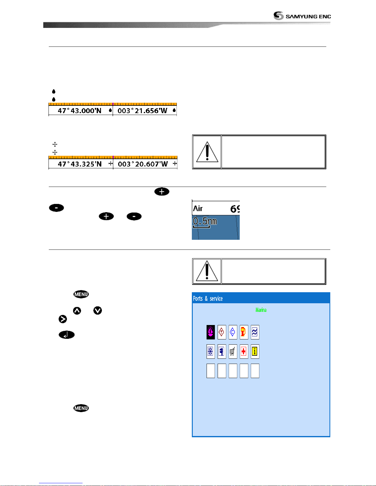
3-4-2 Latitude and longitude
Latitude and longitude coordinates define a
position on earth and can be displayed in
data bar.
In the data bar, own ship position is shown
as below:
47° 43.000‟ N or S Latitude
003° 21.656‟ E or W Longitude
However, if you move the cursor, then the
latitude and longitude in the data bar is the
cursor‟s position as below.
47° 43.325 N or S Latitude
003° 29.607 E or W Longitude
Info
Latitude: Angular distance North or South of
the equator measured by lines encircling the
earth parallel to the equator in degrees from
0° to 90°.
Longitude: angular distance North or South of
the equator measured by lines encircling the
earth parallel to the equator in degrees from
0° to 90°.
When reading the boat
position, make sure the
position is not the cursor
position.
3-4-3 Chart scale
The chart scale change by pressing
to
show more detail information of chart and by
to show wider view of the chart.
When you press or , the scale of
chart is display in the chart on top left corner.
3-4-4 Finding a chart symbol
This function is only available when
NAVIONICS SD card is inserted and
NAVIONICS is selected.
To find a port by name
1 Press .
2 Select Find then Port by name.
3 Press or to select a letter then press
for next letter.
4 Once you enter the name of port, press
.
5 After searching process, select a nearest
port in the list then the cursor will place
on the port you selected on the chart
window.
6 Repeat 2-3 steps of D section to display the
information.
To find port & service
1 Press .
2 Select Find then Port & service.
3 Select a service you want to find.
4 After searching process, select a nearest
service area in the list then the cursor will
place on the service area you selected on
the chart window.
S-MAP does not support this
function.
(See 2-4 for chart selection)
Page 28
Installation and Operation Manual
28
3-4-5 S-Map search
This function is available when NAVIONICS
SD card is inserted and NAVIONICS is
selected.
To find port & service
1 Press .
2 Select Find then Port.
3 Press or to select a port then .
4 After searching process, select a nearest
port in the list then the cursor will place
on the portyou selected on the chart
window.
NAVIONICS Chart does not
support this function.
(See 2-4 for chart selection)
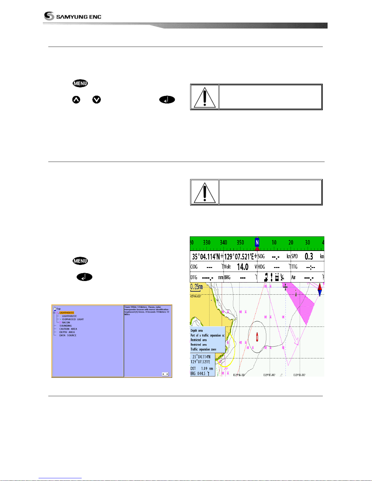
3-4-6 Chart symbols and information
This function is only available when
NAVIONICS SD card is inserted and
NAVIONICS is selected.
Using NAVIONICS card allows you to show
different kind of symbols and their
information on chart plotter display. On some
objects such as a port, you can see a picture
of landscape layout.
To display information
1 Move cursor on an icon to display its name.
2 Press and select Chart info.
3 Move cursor key to highlight an item and
press .
4 Information related to the item appears at
the bottom window.
[Chart info]
S-MAP does not support this
function.
(See 2-4 for chart selection)
[Chart symbol Data Box]
3-4-7 Introduction to navigating
Use the navigation chart to plan your course, view map information, and as a navigational aid.
This unit has two ways of navigating, going st raight to a waypoint or following a route (a
group of waypoints).
Page 29
Installation and Operation Manual
29
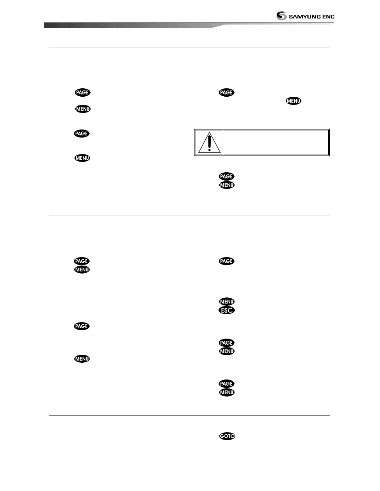
3-4-8 Going to a waypoint or to a point on the chart
A waypoint is a particular location on a voyage whether it is a starting, intermediate or
destination point. A waypoint is the simplest piece of information your equipment requires to
get you to a destination. In the shortest distance possible. This unit can save up to 10,000
waypoints.
Goto Cursor Option
1 Press and select the Chart window.
2 Move the cursor to the destination point.
3 Press and select Goto cursor to
start navigating.
Goto WPT Option
1 Press and select the Chart window
2 Move the cursor to place cursor on a
waypoint.
3 Press and select Goto WPT to start
navigating.
Find Option
1 Press and select the Chart icon.
2 In the Chart window, press
and
select Find then Waypoints.
3 select a waypoint to start navigation.
Make sure the course does
not pass over land or
dangerous waters.
Cancelling navigating
1 Press
and select the Chart icon.
2 Press and select Cancel Goto.
3-4-9 Following a route
Often a trip from one place to another involves several course changes, requiring a series of
route points (waypoints) which you navigate to, one after another. The sequence of waypoints
leading to the ultimate destination is called a route. You can save up to 100 routes and a route
may consist of 100 waypoints.
Start Route Option
1 Press and select the chart window.
2 Press and select Start Route.
3 Move cursor keys to select a route to start
navigating.
4 Select Forward or Reverse to decide
which direction you want to navigate.
Route Window Option
1 Press and select the routes window
2 In the route window, mover the cursor to
highlight a route you want to start
navigating to.
3 Press
and select start
4 Select Forward or Reverse to decide
which direction you want to navigate.
Create Route Option
1 Press and select the chart window.
2 Select New route.
3 Name a route name.
4 Move cursor keys to select a waypoint.
(Repeat this step as much as you need)
5 Press and select Add.
6 Press .
7 Repeat 2-4 steps of Route window option.
Skipping a waypoint
1 Press and select the chart window.
2 Press and select Skip.
3 Repeat above step if necessary.
Cancelling a route
1 Press and select the chart window.
2 Press and select Cancel route.
3-4-10 Goto Key
This key is very useful when you desire to
start navigating to a destination point. When
the key is pressed, it starts navigating to the
point of the cursor or Route.
Going to a point
1 Move the cursor to an open position.
2 Press .
Page 30
Installation and Operation Manual
30
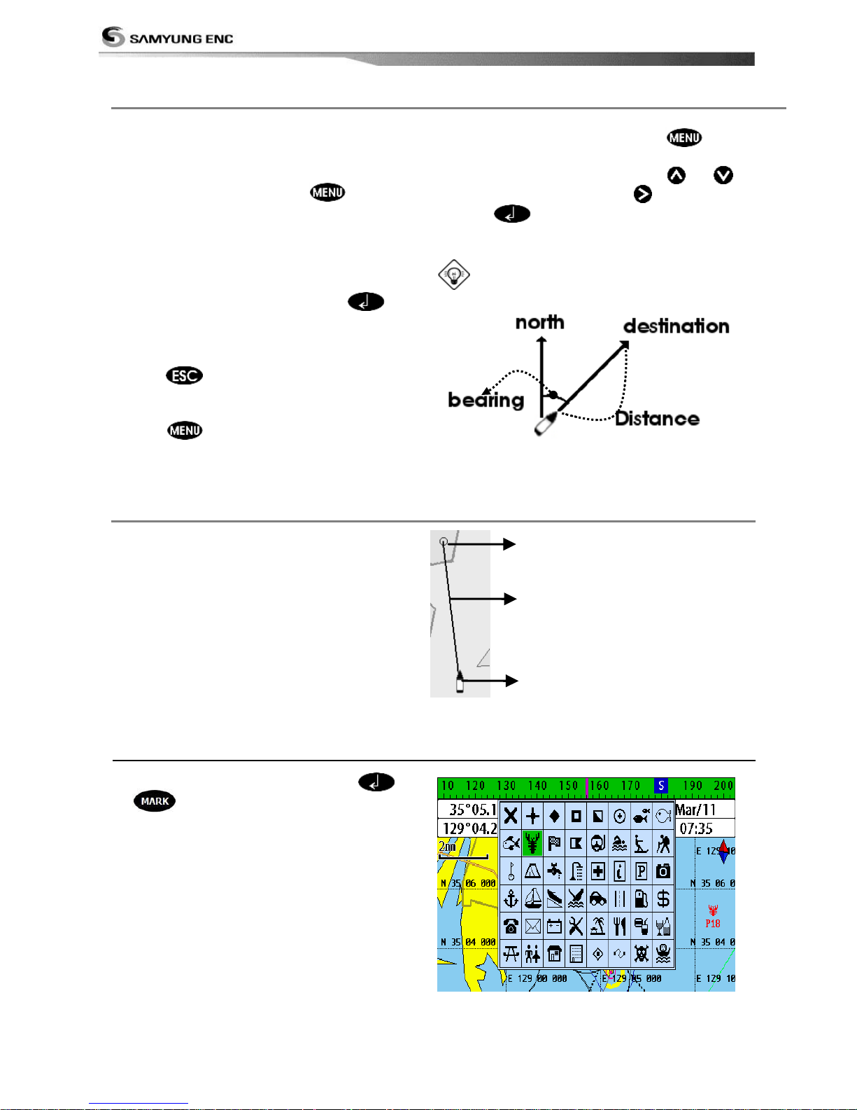
3-4-11 Distance and bearing calculator
The unit can show the bearing and the length
of leg and the total distance of legs.
Setting Legs
1 In the chart window, press
and
select Distance. Information is displayed
on window showing bearing/leg
distance/total distance at bottom pop up
at the bottom left side
2 Move the cursor to the start point which is
start point of first leg and press .
3 Move the cursor to a point which is the end
of first leg.
4 Repeat 2-3 steps for more legs.
5 Press to exit.
Deleting the last leg
1 Press and select Remove.
2 Repeat above step if you want to remove
more legs.
Saving as a route
1 Once you set all the legs, press and select
Save.
2 Enter a route name by pressing or
to
select a letter then press for next letter.
3 Press to save the new route.
Tip: Bearing and distance
3-4-12 Projected course
The projected course shows you how far it
can go at give time and speed.
This function is very useful to avoid collusion
with other vessels.
3-4-13 Finding a chart symbol
In the chart window, press and hold
Or then select destination chart
symbol.
Projected position
Boat‟s projected course
Boat position
Page 31
Installation and Operation Manual
31
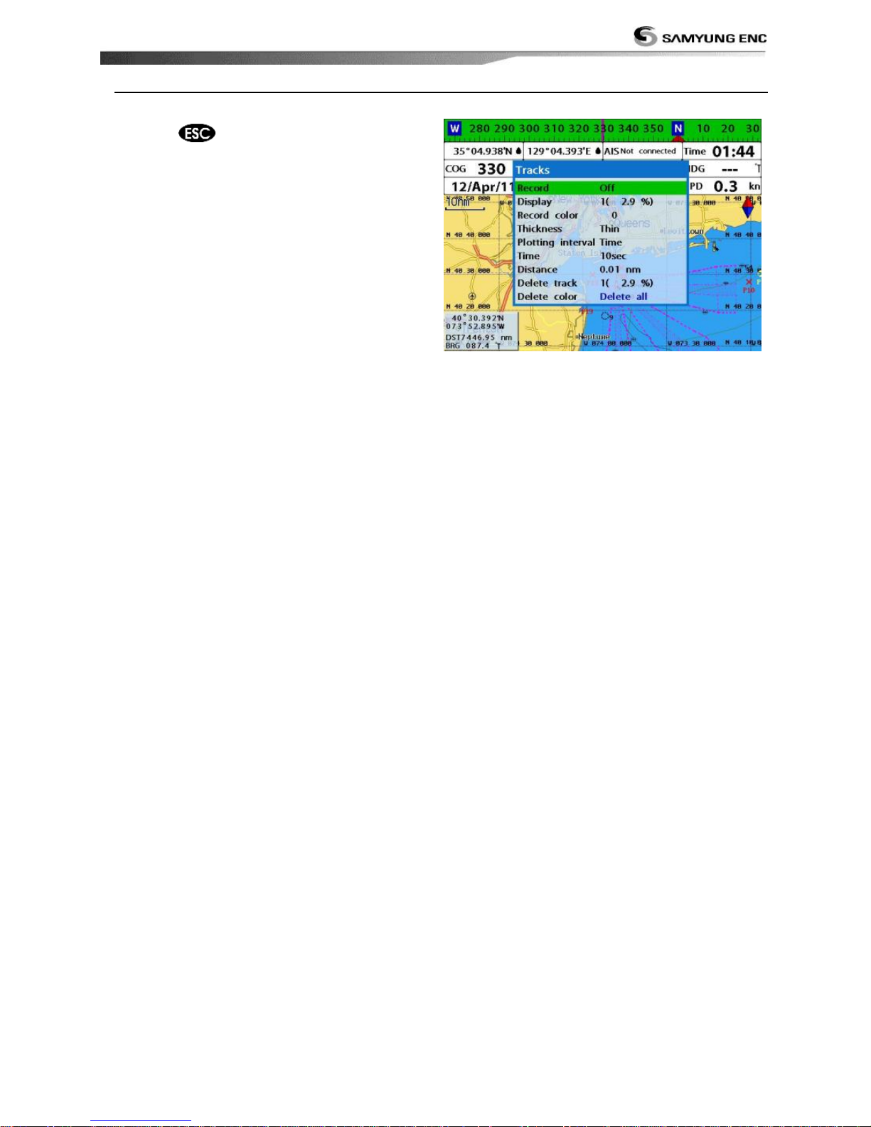
3-4-14 Finding a chart symbol
For tracks setting in the chart window, press
and hold . (See 4-5 Track Setting)
Page 32
Installation and Operation Manual
32
3-5 Sonar
The NF700 proposes a sonar function when the unit is connected to an optional depth
transducer.
To activate sonar function;
1 Press and hold and select System Configuration icon
2 Select Features then Sonar.
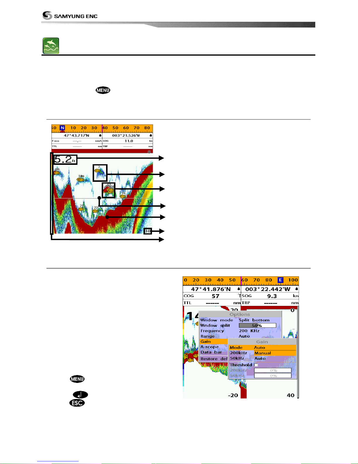
3-5-1 Interpreting the display
① Depth.
② Single fish : Fish symbols with depth.
③ School of fish.
④ Depth line.
⑤ Bottom : Hard bottoms such as rock and
coral shown as wide bands.
Soft bottoms such as mud,
weed and sand show as narrow
bands.
⑥ Range of display.
⑦ Color bar.
The window scrolls from right (recent sonar
record) to left (old sonar record).
3-5-2 Mode
The unit operates in two different modes.
You can choose a mode depending on the
condition.
• Auto mode: This is the most commonly
used option. In this mode, settings are
automatically adjusted for the best display
of fish and bottom according to
environment.
• Manual mode: Use this option for manual
setting. The option might bring you best
result for your purpose.
To change a mode;
1 Press then select Gain.
2 Select Mode then Manual or Auto and
press .
3 Press to exit until returning to the
Chart window.
①
②
③
⑤
⑥
④
⑦
Page 33
Installation and Operation Manual
33
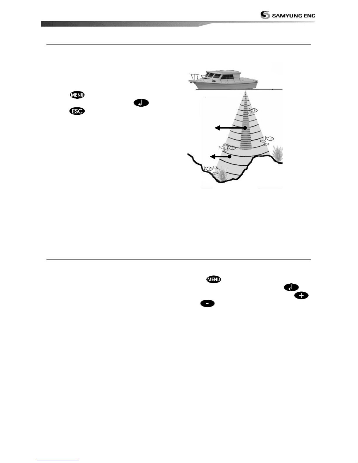
3-5-3 Single and Dual frequency fish finding
Sonar frequencies
The unit has dual frequency, 200kHz and
50kHz to detect various bottom conditions.
To select the sonar frequency in sonar
window:
1 Press , select Frequency.
2 Select frequency and press .
3 Press to exit.
High frequency (200kHz )
The higher ultrasonic signal, the better is the
resolution. For this reason the 200 kHz
frequency is ideal for detailed observation of
fish schools.
Low frequency (50kHz)
The lower frequency signal is, the wider is
the detection area. Therefore, the 50kHz
frequency is useful for general detection and
judging bottom condition.
Mixed frequencies (200kHz / 50kHz)
The Mixed frequency combines the 200 kHz
and the 50 kHz in the Sonar window. The
50kHz picture appears on the left and the
200kHz picture on the right.
The display is useful for comparing the same
picture with two different frequencies.
① High Frequency (200 kHz)
② Low Frequency (50 kHz)
3-5-4 Range
Range is the depth of water displayed on the
sonar window. The basic range may be
chosen in Auto or manual mode.
Auto: When the mode is set to Auto, the
unit adjusts the depth automatically for the
best performance. This option is
recommended for normal operation.
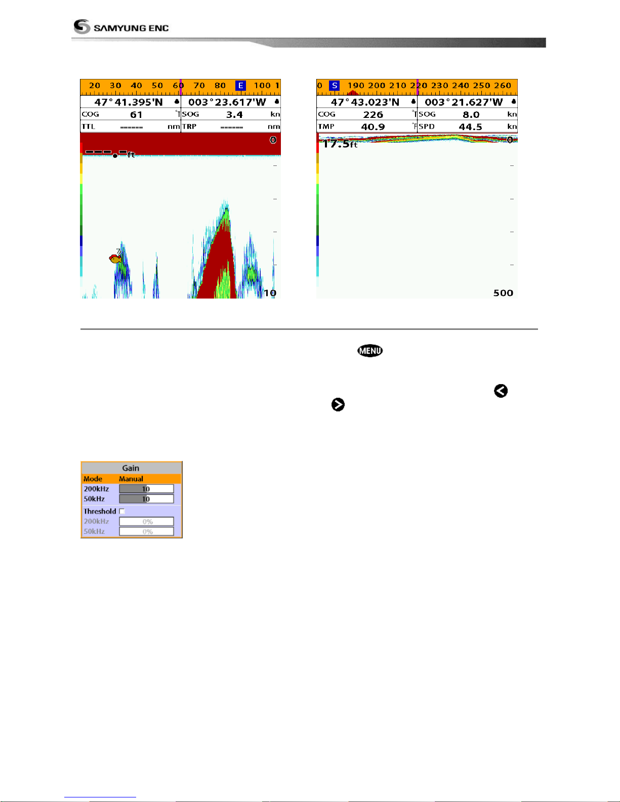
Manual: When the mode is set to Manual,
the unit only displays the depth of water at a
given range. That means the sea bottom
might not be displayed in the sonar window
or it might display half of display in white
because range is more important than sea
bottom depth. As shown in below images.
To set the manual mode in the sonar
window:
1 Press , select Range.
2 Select a mode you want and press .
3 If you select the manual mode, press
or to change value of max
displayed depth.
①
②
Page 34
Installation and Operation Manual
34
[When the set depth is too low]
[When the set depth is too high]
3-5-5 Gain
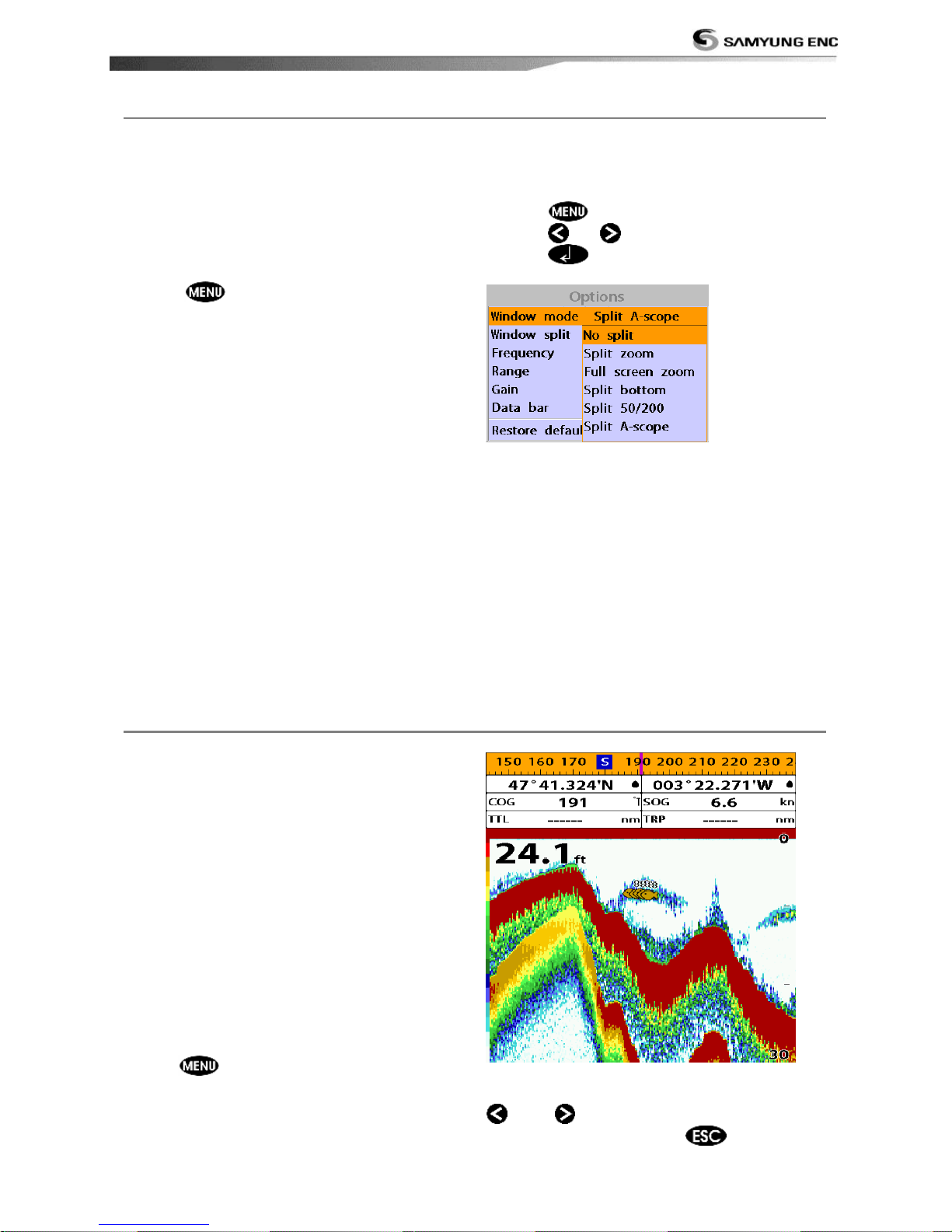
The gain menu
The gain is a signal strength received from
the transducer and the threshold is the level
of ultrasonic that is ignored by a set value.
When you use the manual mode and
threshold, the values of gain and threshold
need to be set very carefully.
In the Gain window, you can set for a gain
mode and threshold.
To change a mode,
1 Press , select Gain.
2 Select a mode.
3 If you select a Manual mode, adjust each
frequency gain value by pressing
or
. Even though you select the Auto
mode, it will be changed to manual mode
if you change the values of frequency.
Page 35
Installation and Operation Manual
35
3-5-6 Sonar window display
Five sonar display windows are available and
each display window has unique
characteristics. Select a display window
depending on your needs. The default display
is No split.
To change a Sonar display window in
the sonar window:
1 Press , select Window mode.
2 Select the sonar display you want.
No split: Display Sonar history at a given
frequency (50 or 200 kHz)
(see section 3-5-7)
Split zoom: This mode expands chosen area
of the normal picture in full vertical size on
the left-half part of the window.
Full screen zoom: Display a zoomed section
on full screen (see section 3-5-8)
Split bottom: Display Sonar history and a
bottom trace focus in a zoomed section (see
section 3-5-9)
Split 50/200: Display the 50 kHz sonar
history on the left and the 200 kHz sonar
history on the right. This display is useful for
comparing the same history with two
different frequencies. (see section 3-5-10)
Split A-Scope: Display Sonar history and
echo strength (see section 3-5-11)
You can change the split ratio if the window
is split.
1 Press
and select Window split.
2 Press or to adjust the ratio.
3 Press .
3-5-7 No split
No split window displays a sonar history at a
given frequency (50 or 200 kHz)
Low Frequency (50 kHz)
The 50 kHz frequency is ideal for detecting
the wider area which means low frequency is
useful for general detection and judging
bottom condition.
High Frequency (200 kHz)
The 200 kHz frequency is ideal provide a
better resolution which means it is ideal for
the observation of fish or fish schools.
To set a frequency for this display:
1 Once you select No split window,
Press .
2 Select the sonar icon then Frequency
3 Select a desired frequency
You can also review old sonar records, press
and
to review the history. To return
to current scanning, press
.
Page 36
Installation and Operation Manual
36
3-5-8 Split zoom and Full Screen zoom
Split zoom
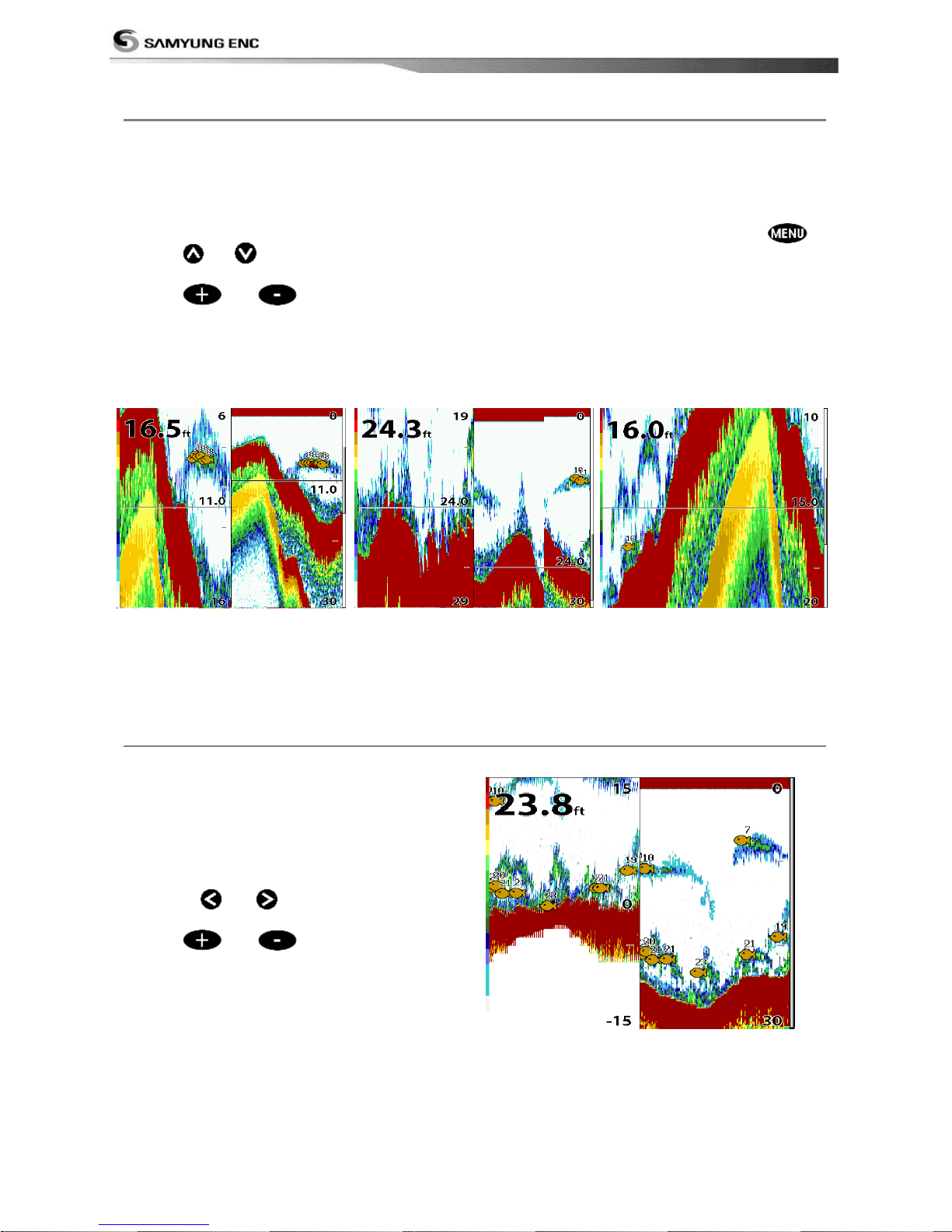
Split zoom mode expands selected area of
the single frequency by VRM(Variable Range
Mark). The left side displays zoomed section
of current sonar record. The VRM of right
side indicates the zoom section area.
• Press or to change the zoom
range.
• Press
or
to change the depth
range.
Bottom lock
If Bottom lock is on, the zoom depth (the
depth of the zoom section) is adjusted
automatically so that the bottom is always
displayed in the zoom section.
• To turn Bottom lock on or off press
Full Screen zoom
Full screen zoom displays only the zoom
section of split zoom.
[Split zoom] [Bottom Lock] [Full screen zoom]
3-5-9 Split bottom
Split bottom display provides a normal
picture on the right half and a selectable
range over and below the bottom line is
expanded onto the left half of the screen.
This mode is useful for detecting bottom
fishes.
• Use the
or keys to adjust the
zoom range.
• Press
or
to change the range
• The VRM moves up and down to calculate
the bottom depth automatically.
Page 37
Installation and Operation Manual
37
3-5-10 Split 50/200
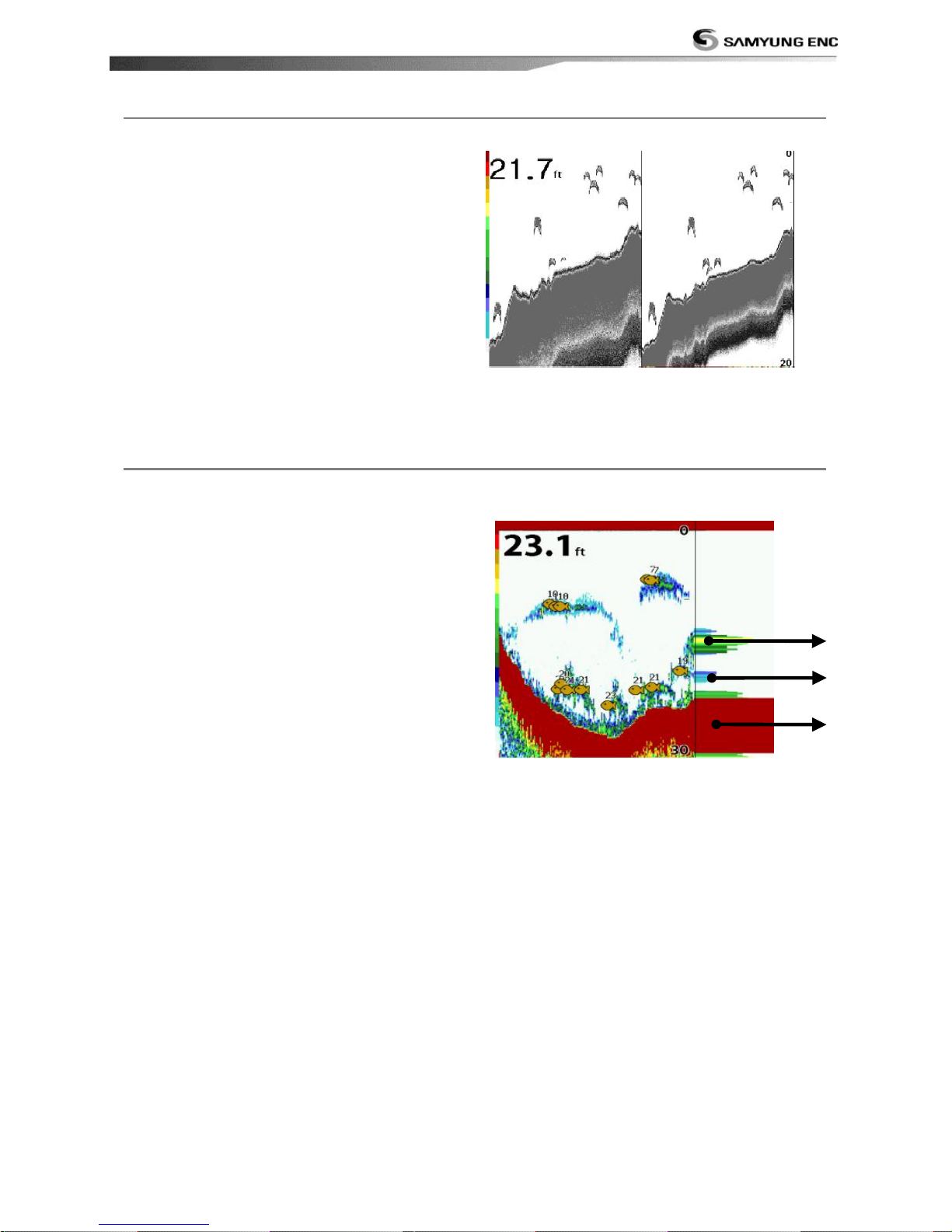
The 50 kHz display appears on the left and
the 200 kHz appears on the right. This dual
frequency display is very useful for
comparing the same scanning with two
different frequencies.
3-5-11 Split A-Scope
This display shows echoes at each
transmission with amplitudes and colors
proportional to their intensities; on the right
of the screen it is useful for estimating the
kind of fish schools and bottom nature.
Echo strength color code varies from weakest
(blue) to strongest (red).
① Echoes from fish and the bottom
② Unwanted noise echoes.
③ The strongest echo, usually from the
bottom.
①
③
②
Page 38
Installation and Operation Manual
38
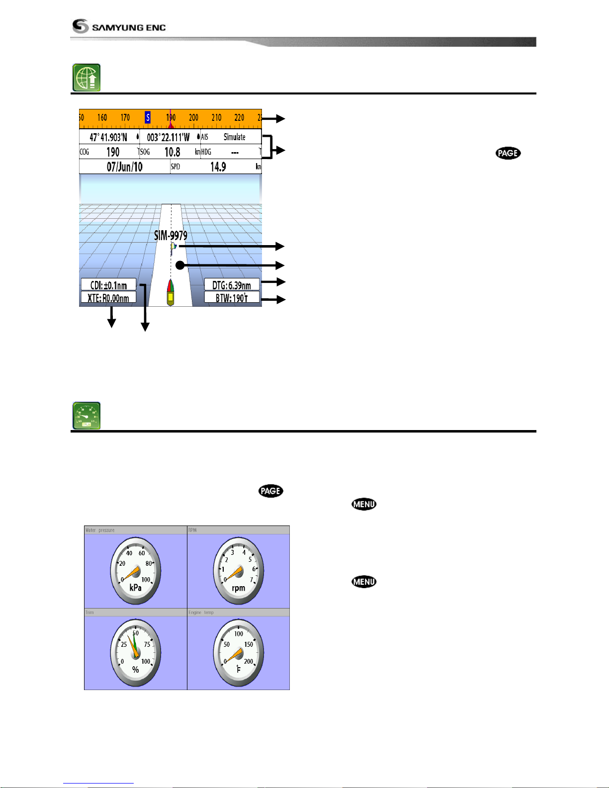
3-6 Highway
The Highway window shows a 3D view of
the vessel traveling through the water when
navigating to a destination point.
To go to the Highway window, press
and select Highway icon.
The Highway window shows:
① Compass.
② Data bar.
③ Destination waypoint.
④ Boat‟s plotted course to destination.
⑤ DTG scale (Distance To Go).
⑥ BTW scale (Bearing to waypoint).
⑦ CDI (Course Deviation Indicator).
⑧ XTE scale (Cross Track Error).
3-7 Gauges
The Gauges window displays all the
information you need during navigation such
as water, engine, fuel related information,
etc.
To select the Gauges window, press
and select Data icon.
Selecting a Gauges layout
The Gauges window can show one of seven
gauge layouts.
To select a layout from the Gauges window:
1 Press
and select Gauge Layout.
2 Select one layout.
Changing a gauge in one selected
To change a gauge displayed in a layout in
Data display.
1 Press and select Gauge Setup then
the upper left side gauge will be
highlighted.
2 Select a gauge you want to change and
select Gauge type.
3 Select a data type you want to display.
①
②
⑤
③
④
⑦ ⑥ ⑧
Page 39
Installation and Operation Manual
39
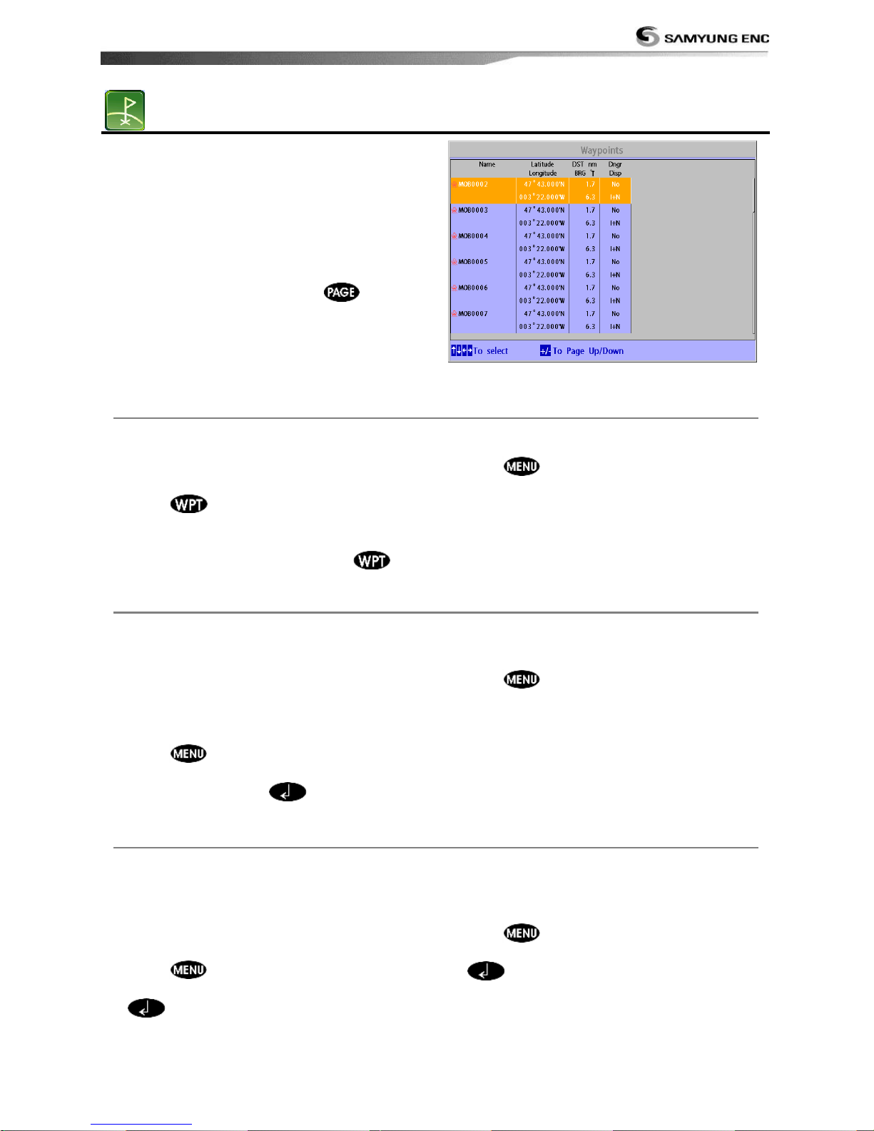
3-8 Waypoints
A waypoint is a particular location on a
voyage whether it is a starting, intermediate
or destination point. A waypoint is the
simplest piece of information the unit
requires to get you to a destination in the
shortest distance possible. This unit can save
up to 10,000 waypoints.
To display waypoint list, press and
select Waypoint icon.
3-8-1 Creating a new waypoint
To create a waypoint from the chart
window
There are two ways to create a new waypoint
from the chart window as described below:
1 Press
on at the current boat
position.
2 Move the cursor to a point where you want
to create a waypoint and press .
To create a waypoint from the
waypoints window
1 Press and select Create.
2 Enter waypoint data, change
alphanumerical name, choose between 48
icons, 16 colors and display option.
3 Select Save.
3-8-2 Moving a waypoint
To move a waypoint from the chart
window
1 Move the cursor to place it on the waypoint
you want to move. (If you move the
cursor on the waypoint correctly,
waypoint information will be displayed at
the bottom left).
2 Press and select Move.
3 Move the cursor to a point where you want
to move and press
.
To Move a waypoint from the waypoints
window
1 Highlight a waypoint you want to move.
2 Press and select Edit.
3 change the existing latitude and longitude
to new position.
4 Select Save.
3-8-3 Editing an existing waypoint
To Edit a waypoint from the chart
window
1 Move the cursor to the waypoint you want
to edit. (If you move the cursor on the
waypoint correctly, waypoint information
will be displayed at the bottom left)
2 Press and select Edit.
3 Edit waypoint data as you need and press
.
To Edit a waypoint from the waypoints
window
1 Move cursor key to highlight a waypoint
you want to edit.
2 Press and select Edit.
3 Edit waypoint data as you need and press
.
Page 40
Installation and Operation Manual
40
3-8-4 Deleting a waypoint
To delete a waypoint from the chart
window
1 Move the cursor to the waypoint you want
to delete. (If you move the cursor on the
waypoint correctly, waypoint information
will be displayed at the bottom left)
2 Press
and select Delete.
3 Select Yes.
Deleting a waypoint from the waypoints
window
1 Move cursor key to highlight a waypoint
you want to delete.
2 Press and select Delete.
3 Select Yes.
A waypoint can not be
deleted if the final
destination of navigation is
the waypoint.
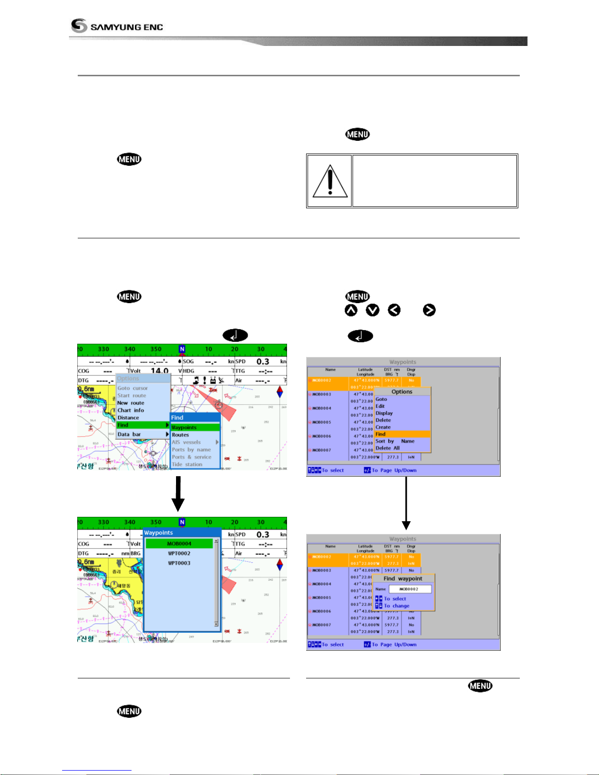
3-8-5 Find a waypoint
To find a waypoint from the chart
window
Finding waypoints from the chart window is a
simplified function.
1 Press and select Find.
2 Select Waypoints.
3 Move cursor key to highlight a waypoint
you want to find and press
.
To find a waypoint from the waypoint
window
Finding waypoints from the waypoint window
is provided by a full function.
1 Press and select Find.
2 Press , ,
or
to find a
waypoint name.
3 Select
.
3-8-6 Sort Waypoints
3-8-7 Deleting all waypoints
To change the order of displayed waypoint
list:
1 Press
and select Sort by.
2 Select a sort type.
1 In the waypoints window, press
and
select Delete all.
2 Select Yes.
Page 41
Installation and Operation Manual
41
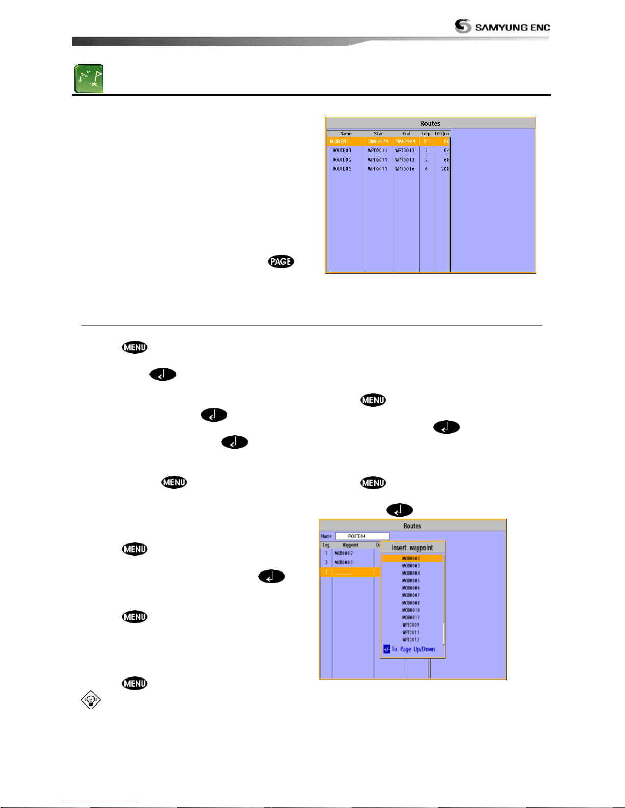
3-9 Routes
A trip from one place to another often
involves several course changes, requiring a
series of waypoints which you navigate to,
one after another. The sequence of
waypoints leading to the final destination is
called a route. The unit can automatically
advance to the next waypoint on a route. So
you do not have to change the destination
waypoint repeatedly.
The unit has the capability to store 100
routes with maximum of 100 waypoints each.
To display the Routes window, press
and select the Routes window.
3-9-1 Managing a route from the chart window
Creating a new route window
1 Press and select New route.
2 Enter the new route name using cursor key
and press .
3 On the Chart window, move the cursor to
the position of the starting waypoint in
the Route and press .
4 Move the cursor keys to the position of
next waypoint and press .
5 Repeat step 4 to enter more waypoints.
6 Once you entered the last waypoint in the
route, press and select End.
Editing a waypoint in route while
creating a route
1 Move the cursor to the waypoint you want
to move.
2 Press and select Move.
3 Move cursor to a position where you wan
to move the waypoint and press .
Deleting a last waypoint from the route
while creating a route
1 Press and select Delete.
Deleting a waypoint from the route
while creating a route
1 Move the cursor to the waypoint you want
to remove.
2 Press and Remove.
Tip: Even though you deleted a waypoint
in the route, the waypoint still remains in the
waypoint list.
Inserting a waypoint while creating a
route
1 If you want to insert a waypoint between
waypoints which will be just after the one
you want to insert.
2 Press and select Insert.
3 Move the cursor to the new inserted
waypoint and press
.
Inserting a waypoint in front of starting
waypoint while creating a route
1 Move the cursor to the starting waypoint
2 Press and select Insert.
3 Move the cursor to the new start location
and press
.
Page 42
Installation and Operation Manual
42
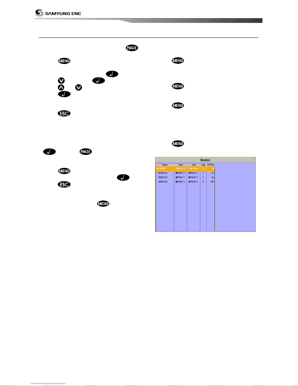
3-9-2 Managing a route from the route window
Creating a rout from the route window
1 To go to the Route window, press
and select the Route icon
2 Press select Create
3 If you want to enter a route name,
highlight name and press .
4 Press and press .
5 Press
or to highlight a waypoint
6 Press to insert a waypoint
7 Repeat step 5 and 6 until you create a
route
8 Press to exit
Inserting a waypoint between two
waypoints
1 In the Route window, select a route you
want to insert in the route list and press
or press and select Edit.
2 Highlight a leg where you want to insert a
waypoint
3 Press and select insert
4 Highlight a waypoint and press .
5 Press to exit
Editing a route in the chart window
1 In the route list, press and select
Edit on chart.
2 Follow the procedure of “Editing a waypoint
in route while creating a route “
Deleting a waypoint in the waypoint list
1 Highlight a waypoint you want to delete in
the waypoint list.
2 Press and select Remove.
Deleting a route in the route window
1 Highlight a route you want to delete.
2 Press and select Delete.
Deleting all route in the route window
1 Press and select Delete All.
Displaying a route in the Chart window from
the route list:
1 Highlight a route you want to display in the
Chart window.
2 Press and select Display.
Page 43
Installation and Operation Manual
43
3-10 Satellites
3-10-1 Satellite information
Acquiring GPS signals
When the unit is first turned on it will take
some time for the GPS signal acquiring. After
signals are received, the unit will
automatically find a position of boat in the
chart window.
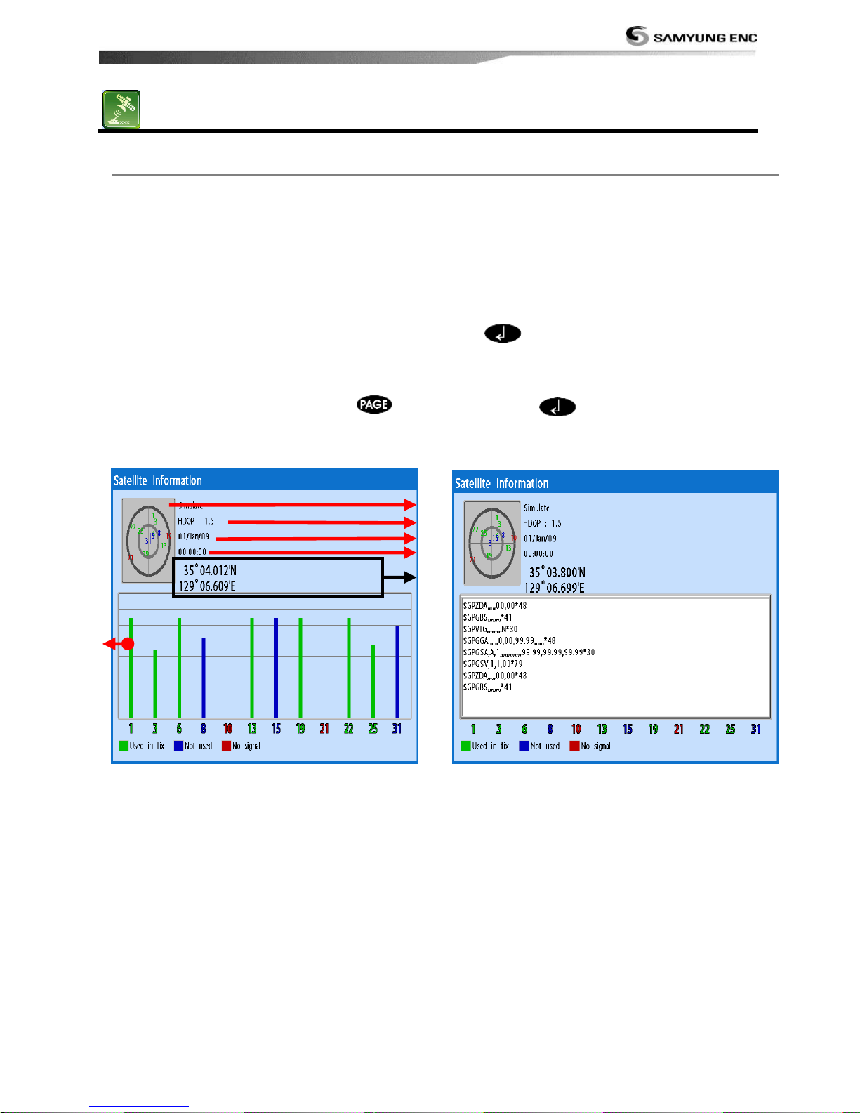
Satellite information window
The satellite window displays different
information about the GPS satellites and GPS
position as below.
To go to the satellite window, press
and select Satellite icon.
The satellite window shows:
① Ship‟s Coordinates.
② Time received GPS satellites.
③ Date received GPS satellites.
④ HDOP: Horizontal Dilution of Precision. It is a
parameter indicating the accuracy of the GPS.
⑤ Location of GPS Satellites.
⑥ GPS signal strengths status in graph.
Press to display GPS signal information
from GPS satellite in NMEA0183 data format
at the GPS signal strengths status display.
To return to GPS signal strengths status
display, press again.
①
② ③ ④
⑤
⑥
Page 44
Installation and Operation Manual
44
3-11 Tides
The Tides window is useful for boaters that
are concerned about the height of the water
or by fisherman that wish to know the tide
and moon phase of a specific date.
Displaying a tide information from the
chart window
1 In the Chart window, press .
2 Select Find and Tide station.
3 Press or to move cursor and select
a tide station
4 Press , ,
or to the position
of selected tide station and press .
5 Select Tide height station to display the
information
6 Press to exit.
Displaying tide station information in
the tides window
1 Press and select Tides window.
2 Select Tide height station to display the
information.
3 Press to exit.
Tip: The unit only displays the tide
information nearest your boat in the tides
windows.
Choosing the date of the tide
information.
1 In the Tides window, Press and
select one of the following options.
- Set date: manually set a date.
- Today: automatically set the date of
today.
- Next day: automatically set the date of
today.
- Prev day: automatically set the date of
yesterday
2 Press to return to the window.
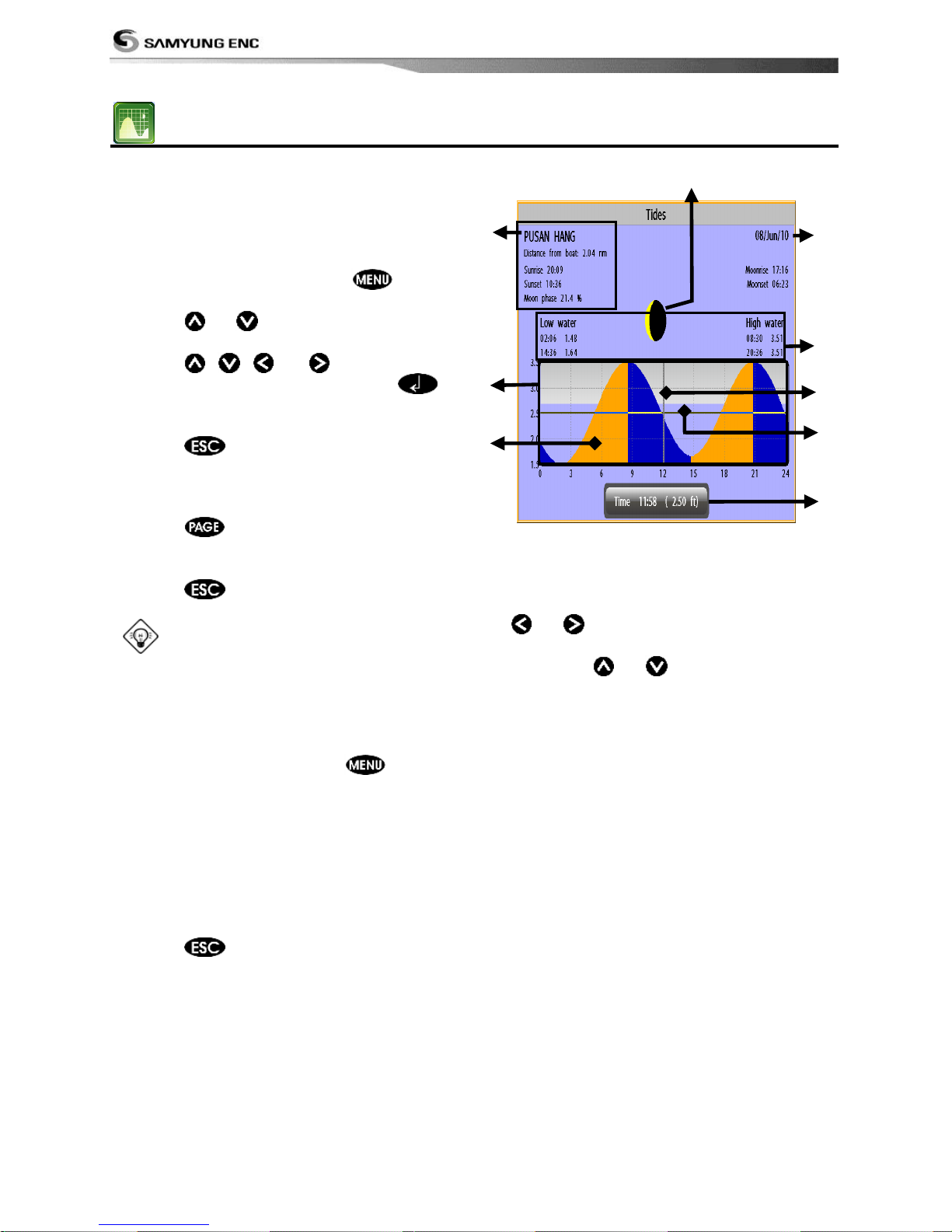
The tides window shows data for the
chosen date
① chosen date for display.
② Data for the chosen date.
③ Time cursor, a vertical dotted line. Press
or to move cursor sideways.
④ Tide height cursor, a horizontal dotted
line. Press or to move cursor up
and down.
⑤ Time of cursor and tide height at that
time.
⑥ Tide station name and distance from boat.
⑦ Moon phase for moon at the current time
on the chosen date.
⑧ Tide chart.
⑨ Tide height.
⑨
⑧
⑦
⑥
⑤
④
③
②
①
Page 45
Installation and Operation Manual
45
3-12 AIS
AIS is an Automatic Identification System for identification and localization of boat. AIS provide
a means for boats to exchange and share boat data including identification, position, course,
etc. This information can be displayed on the screen of you unit. AIS is intended to assist you
to monitor other boats movements to improve safety and prevent collision.
AIS functions require an optional AIS unit to be installed. Contact your nearest Samyung ENC
dealer for more details or visit at www.samyungenc.com.
To activate AIS function:
1 Press and hold and select System Configuration icon.
2 Select Features then AIS.
3-12-1 Viewing AIS Vessels
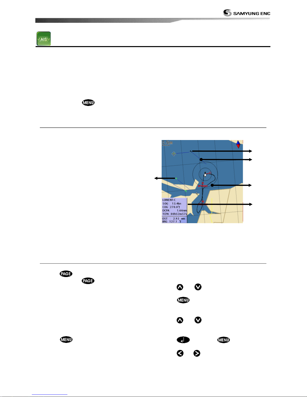
When the unit is connected to AIS unit which
support NMEA0183 or NMEA2000, you can
check other vessel that are equipped with
AIS unit on the screen. To check AIS
information place the cursor on the AIS
object then AIS information displays at the
bottom of window.
① AIS equipped vessel
② Dangerous Vessel
③ Projected Course
④ AIS equipped vessel Data Box
⑤ Range Rings
3-12-2 AIS Windows
To display the AIS windows:
1 Press , and select AIS icon.
2 Press and hold to select one of the
two tabs: Vessels or Messages tab.
- Vessel: show you all the AIS equipped
vessel around you. (up to 200 vessels)
- Message: show you all the messages
related to safety from other AIS equipped
vessels.
Sorting Vessels
1 Press , select Sort by.
2 Select one of the options.
Displaying an AIS vessel on the chart
To overlay AIS equipped vessel on the chart
window:
1 Press
or to select a vessel you
want to display in AIS window.
2 Press
and select Display.
Displaying AIS equipped vessel Details
1 Press
or to select a vessel you
wan to display full AIS detail in the AIS
window.
2 Press or press
and select
More Info.
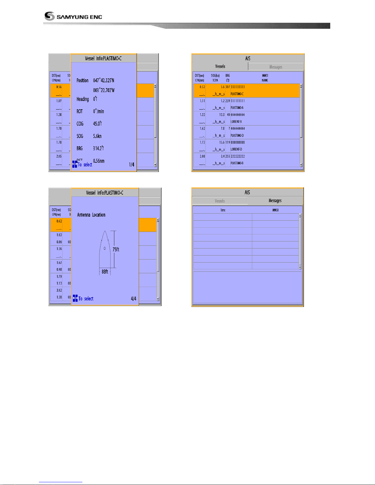
3 Press or to see more detail.
⑤
④
③ ① ②
Page 46
Installation and Operation Manual
46
[AIS Vessel Information -1]
[AIS Vessel Information -2]
[AIS Vessel List]
[AIS Vessel Safety message]
Page 47
Installation and Operation Manual
47
3-13 DSC
This feature requires connection to optional DSC VHF radio.
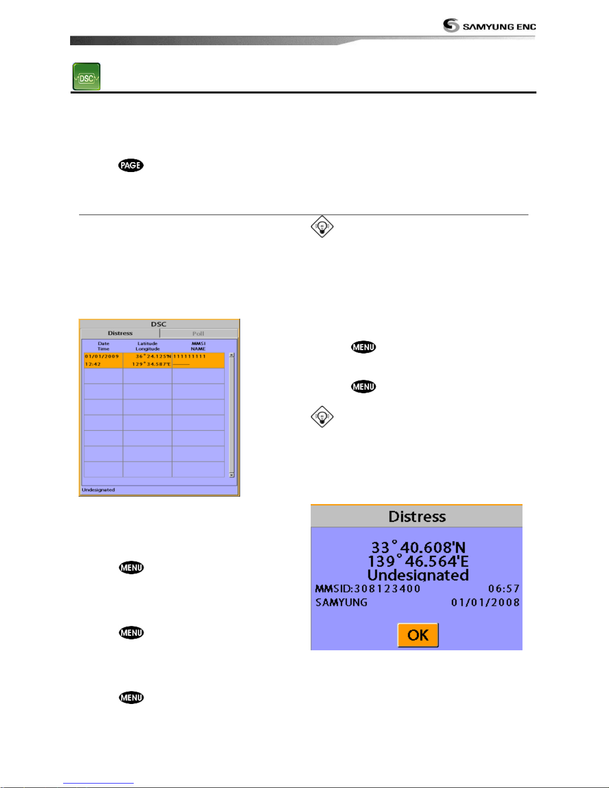
DSC window shows the distress and poll information received from other vessel through DSC
VHF radio.
To go to the DSC windows:
1 Press , select DSC icon.
2 Select one of two tabs: Distress or Poll.
3-13-1 distress
During a distress situation, a vessel that is
equipped with a DSC VHF radio and
connected to GPS has the capability to
transmit a DSC distress call with GPS
position. When a compatible VHF radio
receives a distress call, the distress call
location is displayed on the screen and it is
logged into DSC Distress window.
Displaying a distressed vessel in the
chart window
1 Highlight a received distress call you want
to display.
2 Press and select Display.
Going to the distress position
1 Highlight a received distress call you want
to navigate to.
2 Press and select Goto.
Editing a distress waypoint
1 Highlight a received distress call you want
to edit.
2 Press and select Edit Waypoint.
3 Change data field and select Save.
Tip : When receiving a Distress call from
other vessel, it creates a distress waypoint
automatically. However, the waypoint you
edit in option menu is a different waypoint
from the distress waypoint.
Deleting a Distress Call
1 Highlight a received distress call you want
to delete.
2 Press and select Delete.
Deleting all Distress Call
1 Press and select Delete all.
Tip: Even though you delete a DSC call,
the DSC waypoints still exist.
Distress Message
When the distress message is received, the
distress message will be popped up as below.
Page 48
Installation and Operation Manual
48
3-13-2 Poll
Poll
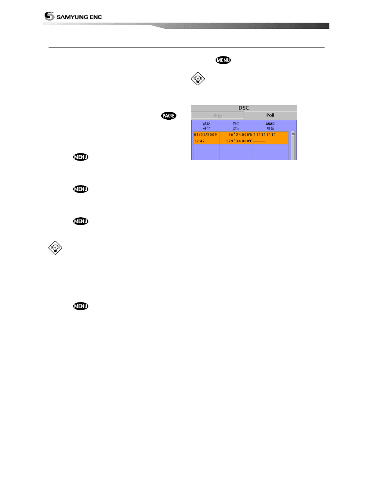
A compatible radio with the unit can request
the position of other DSC VHF radio equipped
vessels around its position. When the position
of a vessel is received, the location is
displayed on the screen and it is logged into
Poll window
To display the Poll tab, press and hold
.
Displaying an poll vessel in the chart
window
1 Highlight a poll you want to display.
2 Press and select Display.
Going to the poll vessel position
1 Highlight a poll you want to go.
2 Press and select Goto.
Edit a distress waypoint
1 Highlight a poll you want to edit.
2 Press and select Edit Waypoint.
3 Change data field and select Save.
Tip : When receiving a poll from other
vessel, it does not create a waypoint as a
distress call
Deleting a poll
1 Highlight a received distress call you want
to delete.
2 Press and select Delete.
Deleting all poll
1 Press and select Delete all.
Tip: Even though you delete a DSC call,
the DSC waypoints still exist.
Page 49
Installation and Operation Manual
49
3-14 NAVTEX
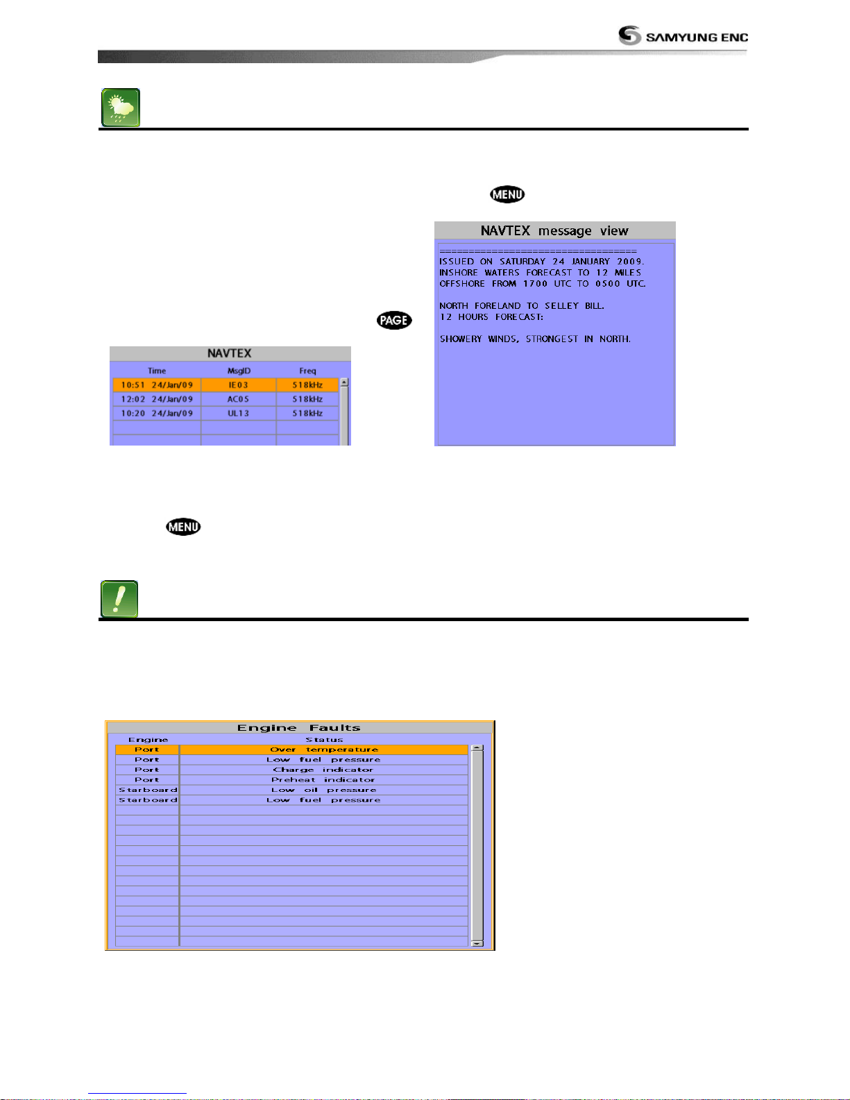
NAVTEX is an international automated direct
printing service for delivery of navigational
and meteorological warnings and forecast, as
well as urgent marine safety information.
NAVTEX functions require an optional
NAVTEX receiver with NMEA0183 output to
be installed and connected to the chart
plotter.
To go to the NAVTEX window, press
and select the NAVTEX icon.
Reloading NAVTEX messages
NAVTEX messages need to be loaded from
NAVTEX receiver manually. (Up to 50
messages)
1 Press and select Reload all.
Deleting a message
1 Move the cursor to a message you want to
delete.
2 Press and select Delete.
3-15 Engine Faults
When connected to a compatible engine
through NMEA2000, F700 & NF700 can
repeat fuel data, and collect engine status.
Engine faults window show you all the errors
or malfunctions of relating to the engine in
real time. If any reason causing a problem is
solved then corresponding error or
malfunction indication will disappear.
Page 50
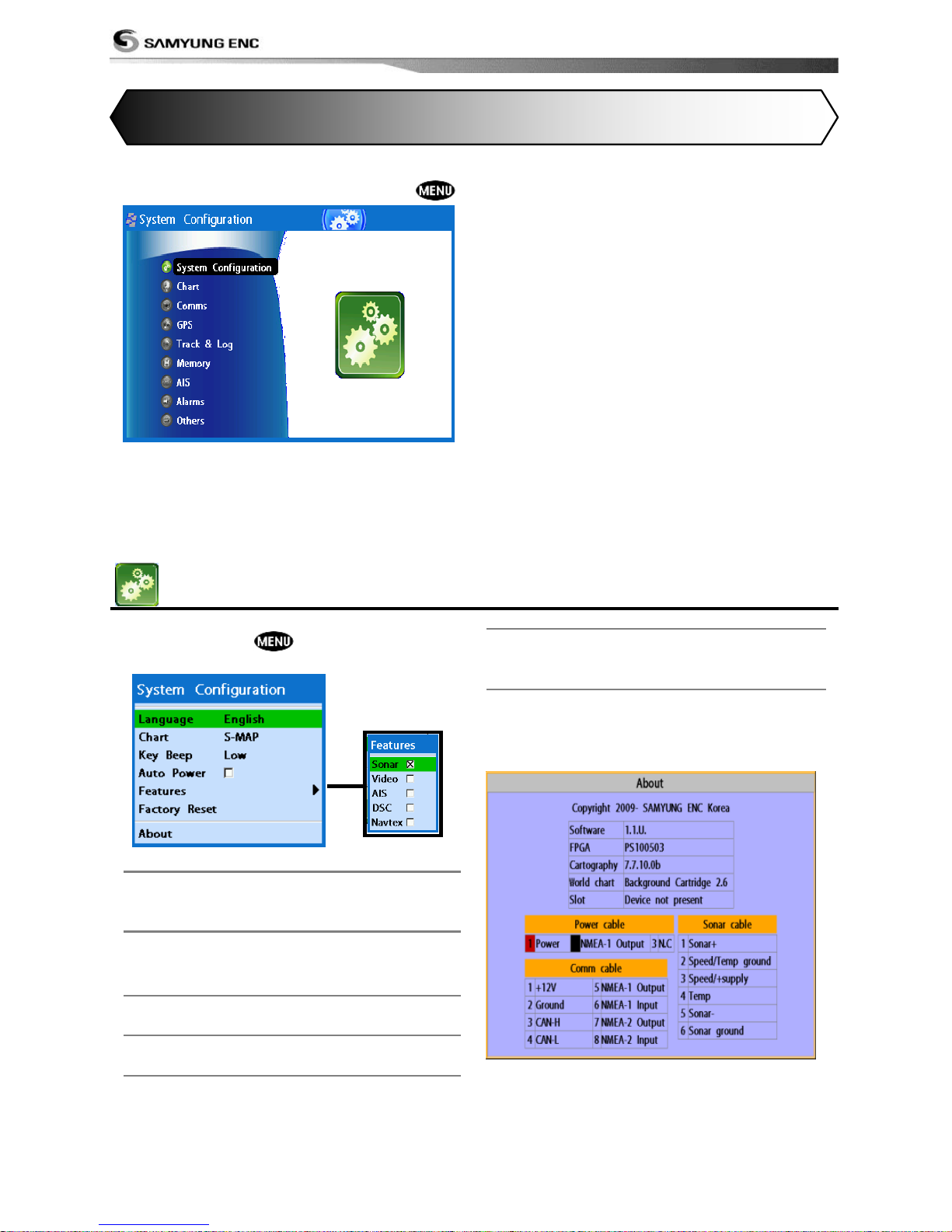
Installation and Operation Manual
50
The system menu mainly consists of settings which do not require frequent adjustment.
To go to system menu, press and hold
then select the icon you want.
① System Configuration.
② Chart.(F700 Except)
③ Sonar.(N700 Except)
④ GPS.(F700 Except)
⑤ Track & log.(F700 Except)
⑥ Memory.
⑦ AIS.
⑧ Alarms.
⑨ Others.
⑩ Set Alpha blending (set transparency of
menu boxes‟ background over main
windows)
4-1 System Configuration Settings
To go to System configuration:
1 Press and hold .
2 Select the system configuration icon.
4-1-1 Language
Change the language for menus and data
screens.
4-1-2 Chart Selection
Select a chart between S-MAP or
NAVIONICS chart.
4-1-3 Beep volume
Select the level of beep sound.
4-1-4 Auto power
See section 3-1.
4-1-5 Features
When external devices are connected to the
unit, the corresponding options need to be
set.
4-1-6 Factory reset
When this option is selected. All settings of
this unit returns to default factory settings.
4-1-7 About
The About window shows:
Software version and release date.
NAVIONICS version.
Wiring information of connector.
4 Advanced Settings
Page 51
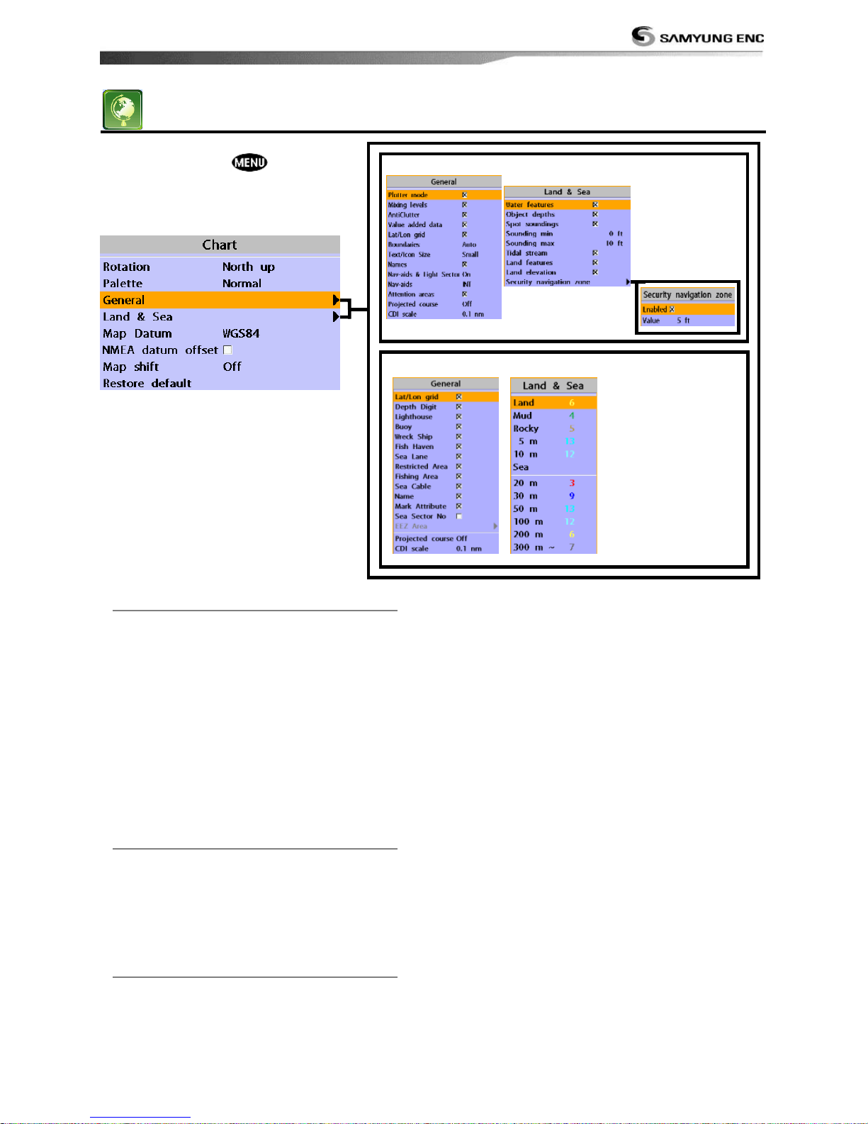
Installation and Operation Manual
51
4-2 Chart Settings
To go to the chart settings:
1 Press and hold .
2 Select the chart icon.
4-2-1 Rotation
Three types of display presentations are
provided. The default is heading up.
North up: North is at the top of the
display.
Heading up: When course is set, the
course is at the top of screen all the
times.
Course up: When destination is set it is
at the top of the screen. This option is
only available when you are navigating to
a destination.
4-2-2 Palette
Palettes are used to enhance the visibility
of the display depending on the
surrounding light environments. Four
types of displays are provided; Normal,
NOAA, Sunlight and Night.
4-2-3-1 General(NAVIONICS)
Plotter mode: this mode allows you to
zoom in and out at scales where
cartographic data are not available.
Mixing levels: when the map coverage at the
current chart scale does not fill the entire display,
the GPS chart plotter draws the rest of map using
charts from above and below the current scale.
When this function is turned on you will notice
the display may redraw 2 to 3 times to show all
the detail.
AntiClutter: when this option is selected, less
important information (names & icons) are hiden
when they are overlapped.
Value added data: The Value Added Data(VAD)
is a collection of additional cartographic objects
which are not present on the original paper
chart. These objects have been obtained from
other sources and then merged to the electronic
charts in order to provide more information
useful for the navigation.
Lat/Lon Grid: Turns the displaying of the
latitude and longitude grid lines on or off on the
chart window.
S-MAP
NAVIONICS
Page 52
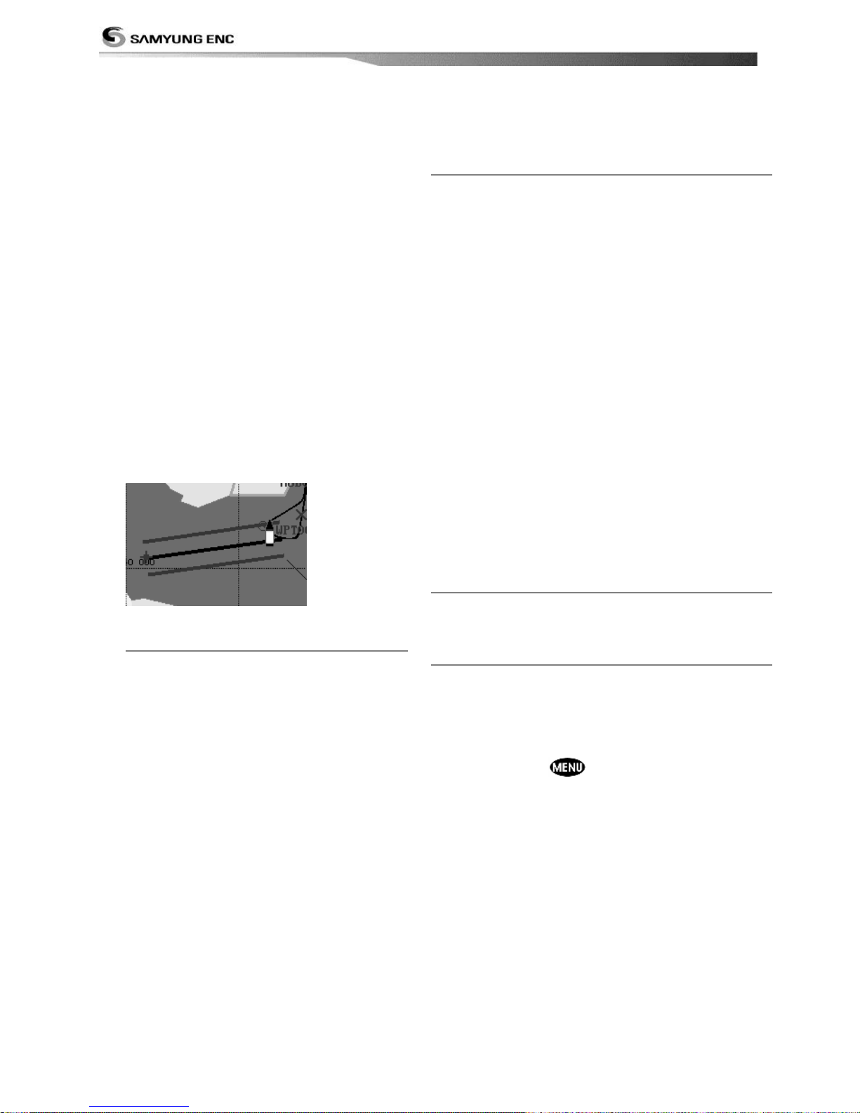
Installation and Operation Manual
52
Boundaries: Turns the displaying of
chart boundaries on, off or auto mode
which shows the chart boundaries of the
two charts below the current scale.
Text/Icon Size: change the size of text
and icon on the chart.
Names: Display area names in the chart.
Nav-aids & Light Sector: Turns the
presentation of Light, Signals, Buoys and
Beacons On, Off, No Sector (Nav-Aids are
shown, Light Sectors are hidden) or
Animated (The lights are flashed).
Nav-aids: The way to display fog, radar
and radio station signals. (International
and US)
Attention areas: Turns the displaying of
Attention Areas where need to pay
attention more) On or Off.
Projected course: Display the Projected
course in given set time.
CDI scale: Set CDI (Course Deviation
Indicator) scale which is a parallel line on
either side of the pottered course.
4-2-3-2 General(S-MAP)
Lat/Lon grid: Turns the displaying of
Lat/Lon on or off
Depth Digit: Turns the displaying of
water depth on or off
Lighthouse: Turns the displaying of
Lighthouse on or off
Buoy: Turns the displaying of buoys on
or off
Wreck Ship: Turns the displaying of
Wreck Ship on or off
Fish Haven: Turns the displaying of Fish
Haven on or off
Sea Lane: Turns the displaying of Sea
Lane on or off
Restricted Area: Turns the displaying of
Restricted area on or off
Fishing Area: Turns the displaying of
Fishing Area on or off
Sea Cable: Turns the displaying of Sea
Cable on or off
Name: Turns the displaying of area name
on or off
Mark Attribute: Turns the displaying of Mark
Attribute on or off
Sea Sector No: Turns the displaying of Sea
Sector No on or off
4-2-4-1 Land & Sea (NAVIONICS)
Water features: Turns the displaying of sea bed
nature and tide stations icon on or off.
Object depths: Turns the displaying of object
depths on or off.
Spot soundings: Turns the displaying of spot
sounding on or off.
Sounding min: Set the minimum depth limit to
show depth sounding, bathymetric lines and depth
area.
Sounding max: Set the maximum depth limit to
show depth sounding, bathymetric lines and depth
area.
Tidal stream: Turns the displaying of tidal
streams on or off.
Land Features: Turns the displaying of land
features on or off.
Land elevation: Turns the displaying of land
elevations on or off.
Safe Navigation Area: Set the water depth for
safe navigation and displaying safe navigation area
in color.
4-2-4-2 Land & Sea (S-MAP)
Turns the displaying of sea color in 16 different
colors.
4-2-5 Map datum
This unit has a compatibility with most of major
chart system and this option allows you to select a
map datum. The default datum is WGS84.
Map datum Selection
1 Press and hold and select chart icon
2 Select general and Map datum
3 Select a desired map datum
Page 53
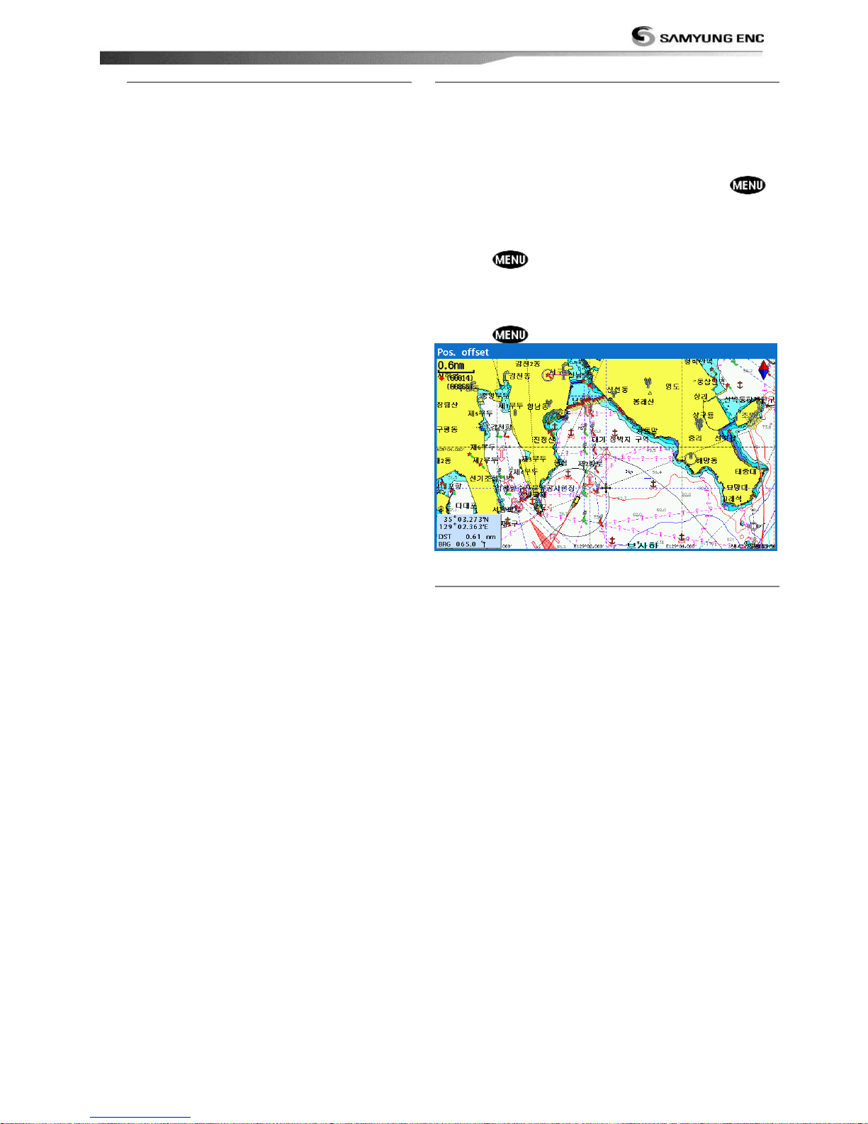
Installation and Operation Manual
53
4-2-6 NMEA datum offset
When you select other Map datum
different from WGS84, latitude and
longitude will be different from WGS84‟S
coordinates and this might confuse other
device such as VHF radio if connected to
the unit. If this option is applied, latitude
and longitude send on the unit NMEA
output will be the same as coordinates in
WGS84.
4-2-7 Map shift
Sometimes current position of own ship does not
match with the current location on the chart. To
correct this position error, you can apply a map
shift.
Applying a map shift
1 In the Chart setup menu, press and hold
and select Chart icon.
2 Select Map shift to ON.
3 Move cursor to the actual position on the chart.
4 Press and select Set.
Canceling a map shift
If you want to clear the map shift:
1 In the Chart setup menu, select Map shift.
2 Press and select Clear.
4-2-8 Restore default
Returns every chat settings to default.
Page 54
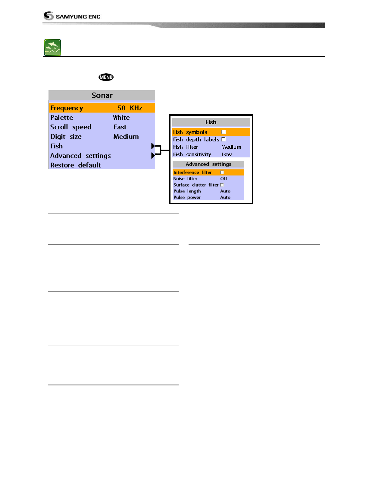
Installation and Operation Manual
54
4-3 Sonar Settings
Sonar feature requires a connection to depth transducer.
To go to the Sonar settings:
1 Press and hold .
2 Select the Sonar icon.
4-3-1 Frequency
You can select a sonar frequency among 200
kHz, 50 kHz or Mixed.
4-3-2 Palette
Palettes are used to enhance the visibility of
the display depending on the surrounding
light environments. Three types of displays
are provided black, blue and white.
4-3-3 Scroll speed
You can set the scroll speed which
determines how quickly the vertical scan lines
run across the screen. Five speed options are
provided; Very Fast, Fast, Medium, Slow and
Pause.
4-3-4 Digit size
You can change the size of the depth window
on the Sonar window. Three options are
available Small, Medium or Large.
4-3-5 Fish
Fish symbols: Turn the fish symbol on or
off.
Fish depth labels: Turn the fish depth
value on or off.
Fish filter: Select a minimum fish size that
will be displayed as a fish symbol.
Fish sensitivity
Select the minimum strength fish echo that
will be displayed as a fish symbol.
4-3-6 Advance Settings
Interference filter: Interference from other
equipment operating nearby or on your boat
may show itself on the display. Use this
option to remove interference.
Noise filter: If there is noise, the echo
signal from transducer is not stable. This
function remove noise and averages the echo
signal. However, this option may also remove
fish echoes.
Surface clutter filter: This filter removes
surface noise. However, the function does not
remove fish echoes.
Pulse length: You can select specific pulse
length of transducer. A short pulse shows
more detailed information but can‟t show
deeply into the water because of less power.
The Auto setting is recommended.
Pulse power: You can select specific pulse
power of transducer. Low power shows a
clear display but can‟t show deeply into the
water. The Auto setting is recommended.
4-3-7 Restore default
Returns every sonar settings to default.
Page 55
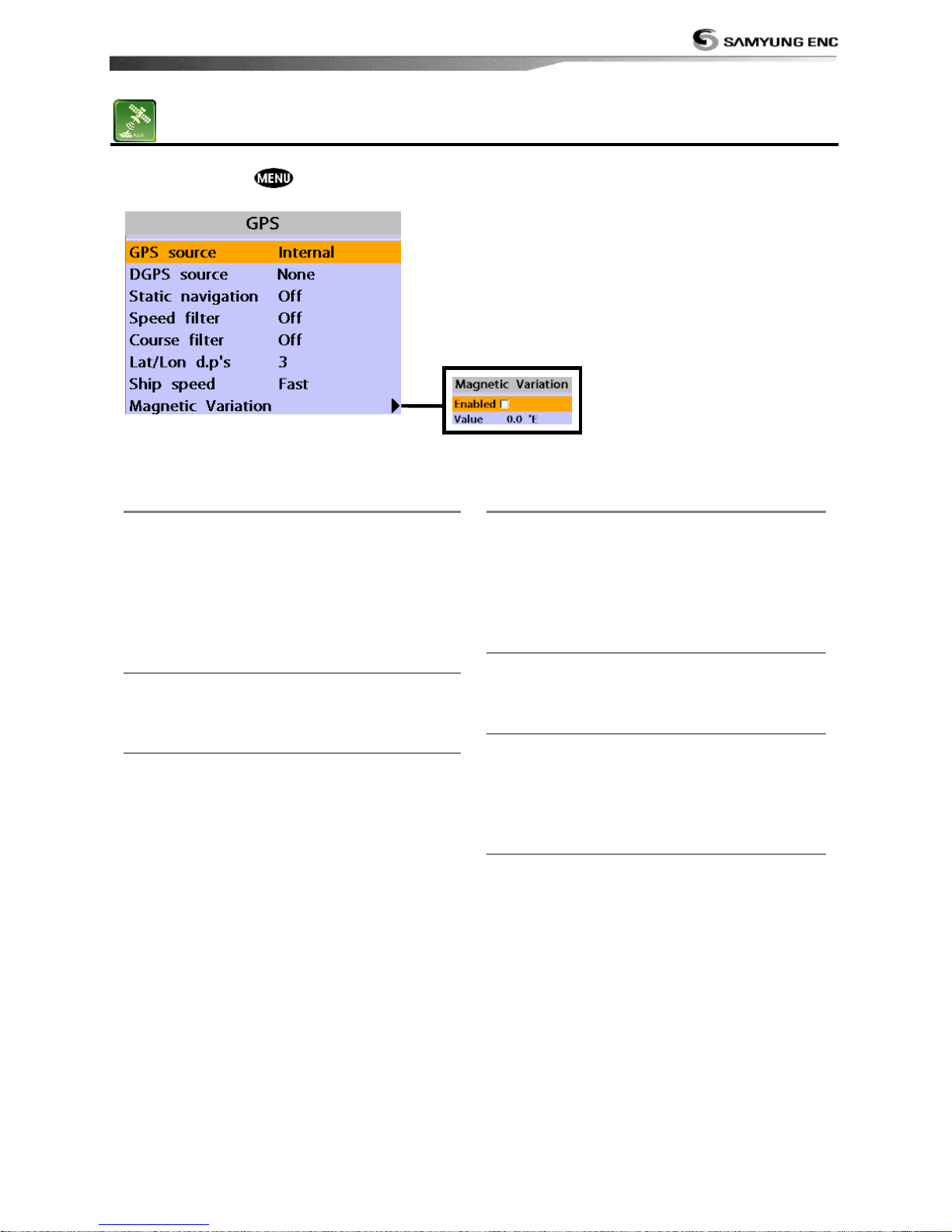
Installation and Operation Manual
55
4-4 GPS Settings
To go to the GPS settings:
1 Press and hold .
2 Select the GPS icon.
When the GPS device is connected properly, the GPS settings provide the access to GPS
functions and features connected with the satellites information used for further navigation.
4-4-1 GPS Source
Select a source of GPS signals
Internal: Select this option when uses the
internal GPS antenna.
NMEA0183 & NMEA2000: Select this
option when using an external GPS or DGPS
antenna via NMEA.
4-4-2 DGPS Source
Select WAAS/EGNOS when you want to
utilize DGPS.
4-4-3 Static Navigation
This option is very useful when the boat
stops or moves very slowly. This option
allows you to set a minimum speed at which
movement is assumed. The value range is
from 0.00 to 9.99.
4-4-4 Speed Filter and Course Filter
Occasional waves and wind at sea affect the
boat speed and course. In order to have
stable boat speed and course, the unit
calculates these factors to give the value of
stable speed and course information.
4-4-5 Lat/Lon d.p’s
Select number of last digit of Lat/Lon to be
sent to other marine electronics.
4-4-6 Ship speed
To have more precise boat speed and course,
you can select your boat speed. Mid is highly
recommended option for the most of
common boat.
4-4-7 Magnetic Variation
This option compensates the difference
between true north and magnetic north.
Page 56
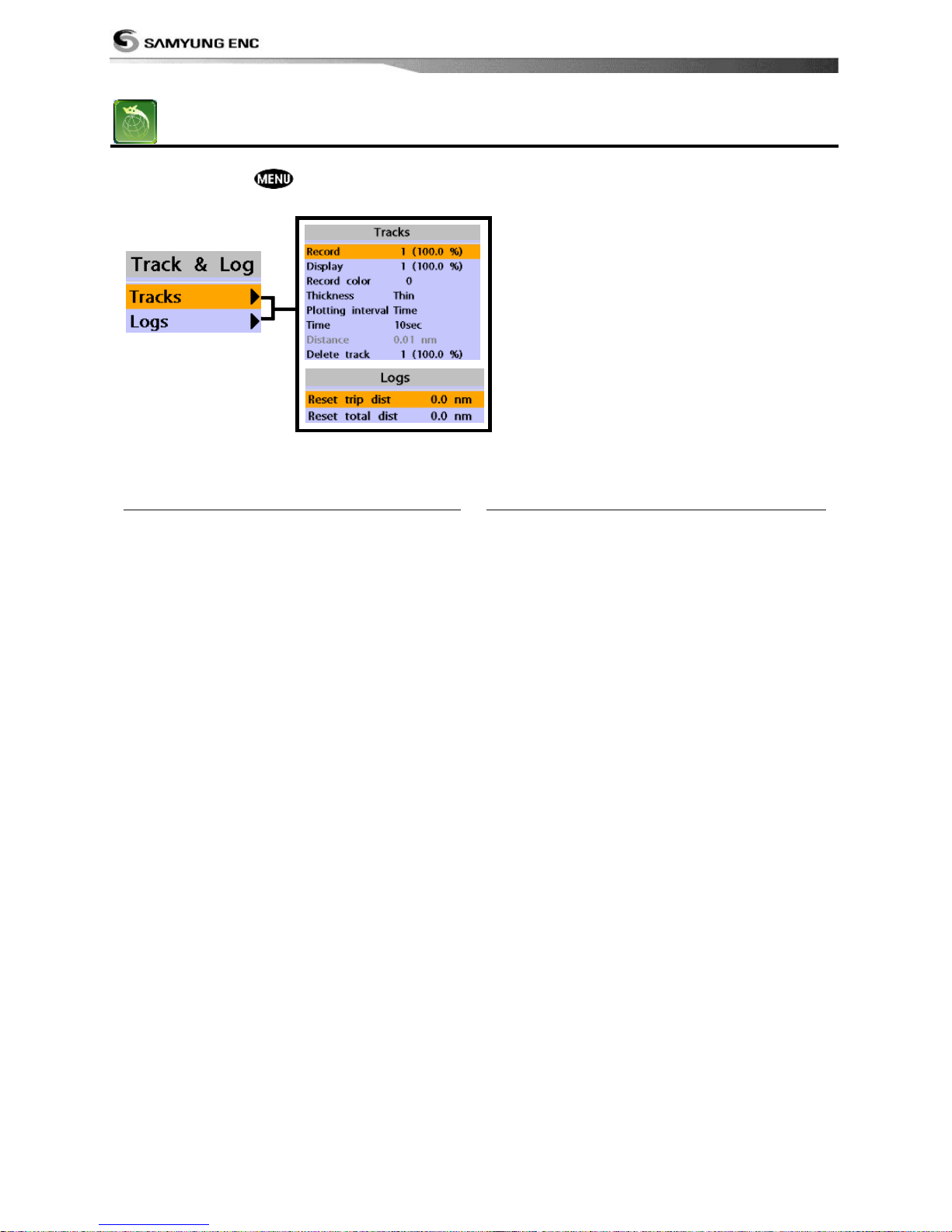
Installation and Operation Manual
56
4-5 Track & Log Settings
To go to the tracking and long settings:
1 Press and hold .
2 Select the track & log icon.
The unit has the capability to store 10 individual tracks and record up to 15,000 track points.
Before using the track function you will need to setup the track function that suits your boat.
4-5-1 Track
Record
Off: Stop a recording of Track
1 to 10 (select a track number): Start a
recording of the boat‟s course.
Display
Off: Display no track on the chart.
1 to 5 (select a track number): Display a
selected track on the chart.
Record color
Select the color of recording track.
Thickness
Select the thickness of recorded track.
Plotting Interval
Select the method of plotting interval
between time and distance.
Distance
Select the distance of plotting interval.
Time
Select the time of plotting interval.
Delete track
Delete a selected track record.
4-5-2 Logs
Reset trip dist
Shows you the trip distance. If you select this
option it resets the trip distance.
Reset total dist
Show you the total trip distance. If you select
this option it resets the total trip distance.
Page 57
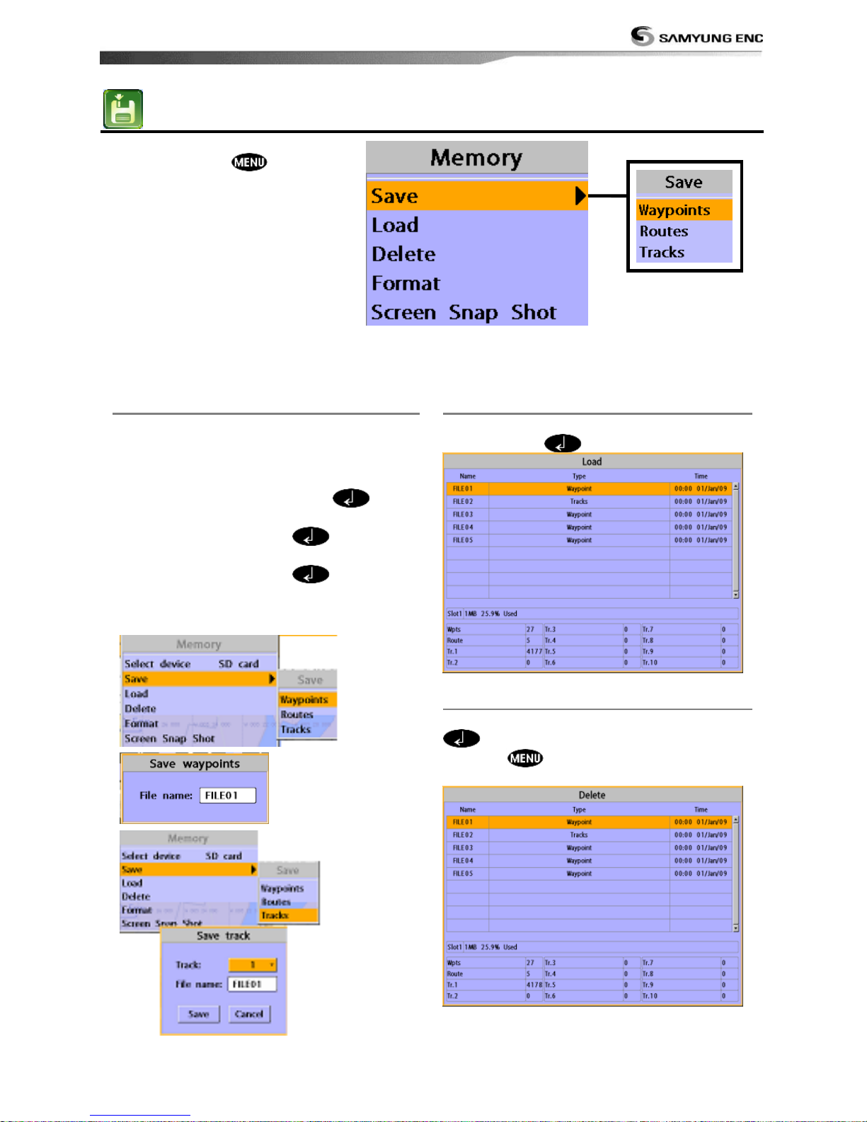
Installation and Operation Manual
57
4-6 Memory Settings
To go to the memory settings:
1 Press and hold .
2 Select the Memory icon.
A user card is an option SD card which you need to purchase additionally.
Before you use a user card it must be formatted. Note that formatting a user card erases all
saved data.
4-6-1 Save
Select a data type you want to save in the
user card then the data will be saved in the
user card automatically.
1 If you select waypoint for saving data,
enter the file name and press .
2 If you select routes for saving data, enter
the file name and press .
3 If you select tracks for saving data, enter
the file name and press .
[Waypoints] [Tracks]
`
4-6-2 Load
Select a data you want to road into the load
list then press .
4-6-3 Delete
Select a data you want to delete then press
.
(Press and select sort by name.
Also, you can sort the file by name.)
Page 58
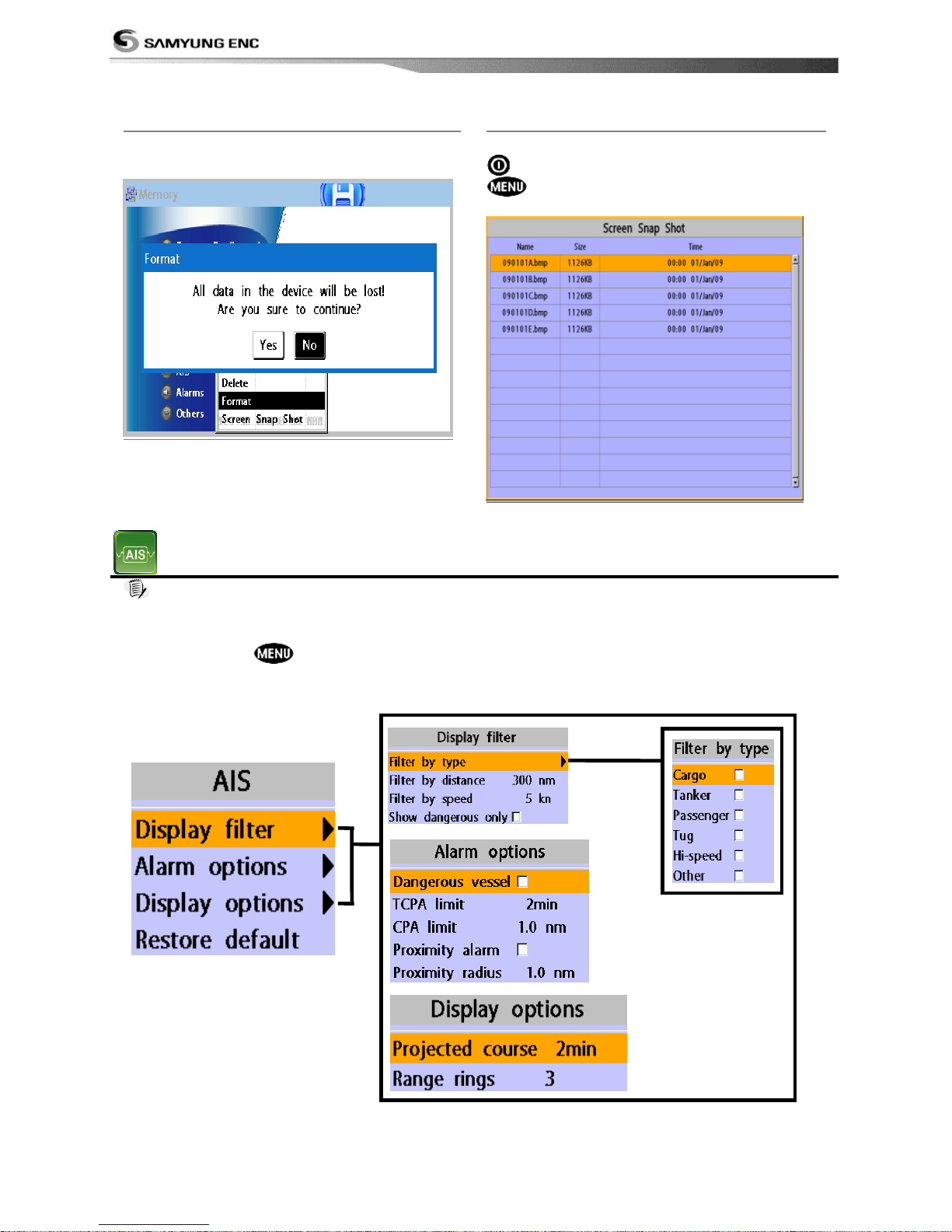
Installation and Operation Manual
58
4-6-4 Format
Erase all data in the user card. Format the
user card before using it.
4-6-5 Screen snap shot
To take the snap shot of current screen, press
twice. To save the captured image, press
and select Save or Save all to save
the captured images on the user card.
4-7 AIS Settings
Note
AIS feature require an optional AIS receiver.
To go to the AIS settings:
1 Press and hold .
2 Select the AIS icon.
Page 59
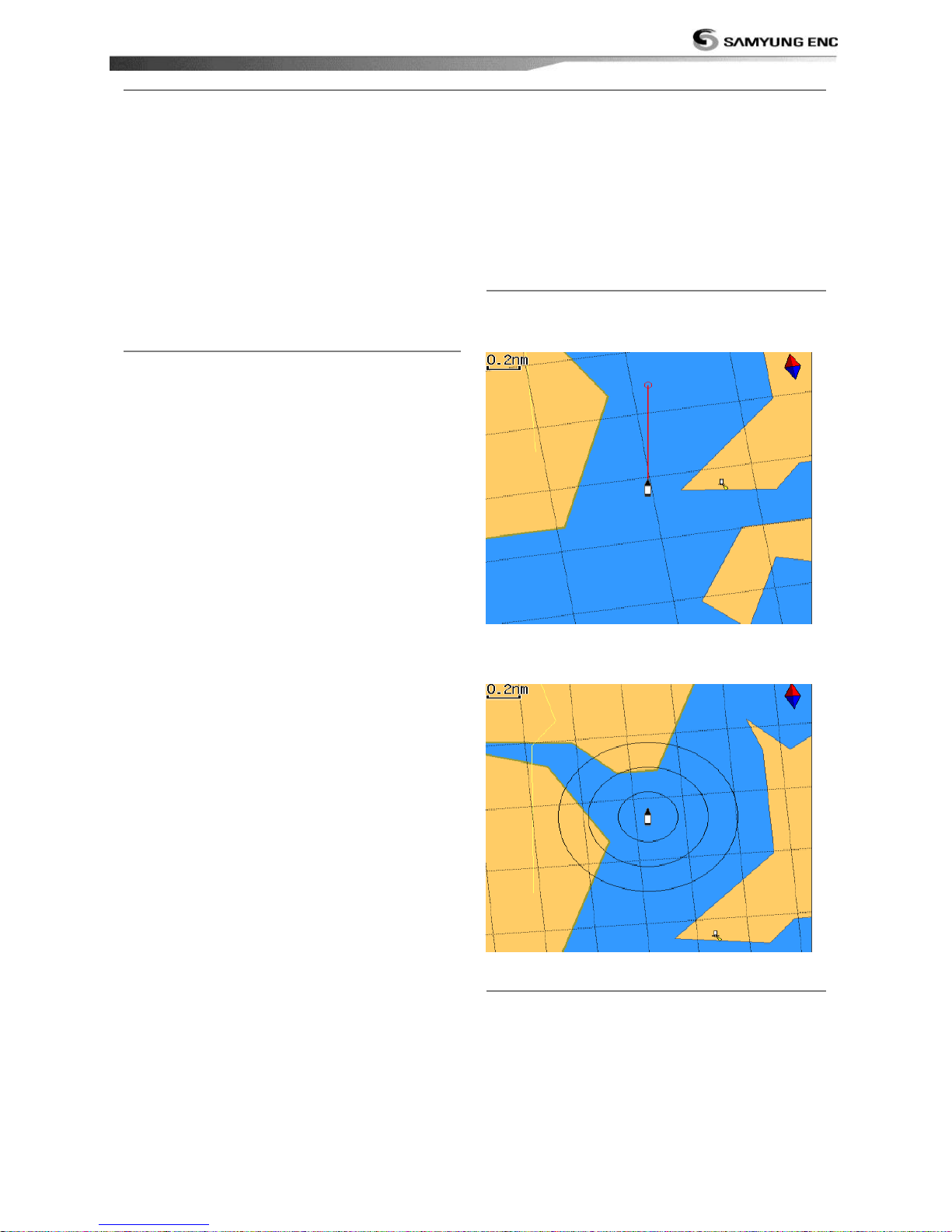
Installation and Operation Manual
59
4-7-1 Display filter
There are a couple of methods to filter AIS vessel in this unit as below.
Filter by Type : The type of vessel which is
selected will not be displayed on the chart.
Filter by distance : Vessels outside the
radius of selected distance from own ship is
filtered.
4-7-2 Alarm option
Dangerous Vessel Alarm : When this
option is selected an alarm will activate. Even
this option is not selected; dangerous vessels
will still be on the chart.
TCPA Limit : Set the Time of Closet Point of
Approach limit.
CPA Limit : Set the Closet Point of Approach
limit.
Proximity alarm : Trigger an alarm when
any AIS equipped vessel is within a set
proximity radius.
Proximity radius : Set a radius for
proximity alarm.
Filter by speed : Vessels with speed below
the set value are filtered.
Show Dangerous Only : When this option
is selected, it shows dangerous vessel only.
4-7-3 Display options
Projected course : Set a time for projected
course. The project course show the estimate
course of vessel base on the given time.
Range rings : Select a number of Range
rings.
4-7-4 Restore default
Returns every AIS setting to default.
Page 60
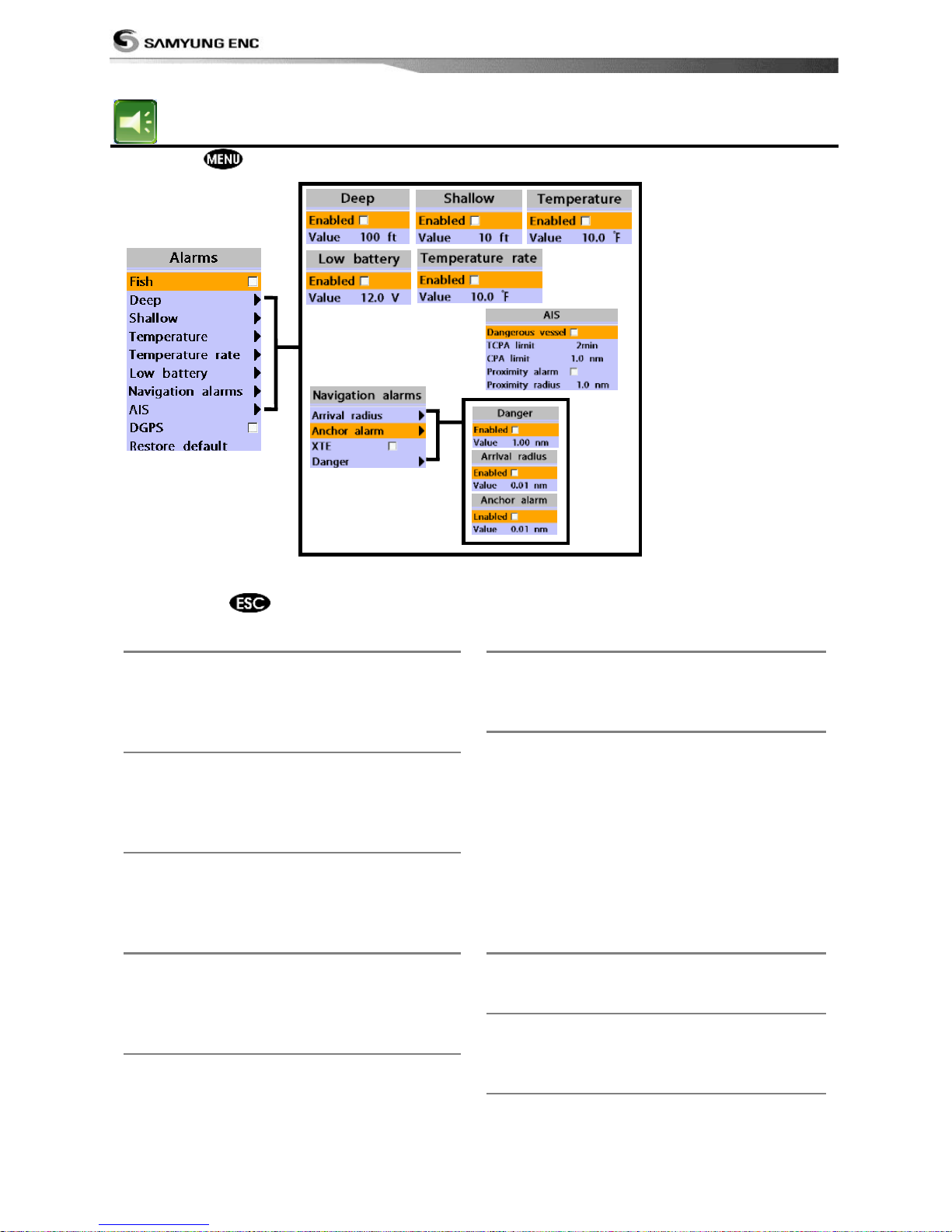
Installation and Operation Manual
60
4-8 Alarms
Press and then Alarms:
A warning message with beep sound is displayed when an alarm condition is met by user
setting. Press
to clear the alarm. However, the alarm will be displayed again when the
alarm condition occurs again. The unit provides alarms for various functions.
4-8-1 Fish
Trigger an alarm when echo from the
transducer is matched to preprogrammed fish
profile.
4-8-2 Deep
Trigger an alarm when the depth value
received from the transducer is deeper than a
set value.
4-8-3 Shallow
Trigger an alarm when the depth value
received from the transducer is shallower
than a set value.
4-8-4 Temperature
Trigger an alarm when the reported
temperature from the transducer is same as
a set value.
4-8-5 Temperature rate
Trigger an alarm when the rate of
temperature change from the transducer is
same as a set value.
4-8-6 Low battery
Trigger an alarm when battery voltage is
lower than a set value.
4-8-7 Navigation alarms
Arrival radius : Trigger an alarm when your
boat is approaching the destination to set
value
Anchor alarm : Trigger an alarm when your
boat moves more than set valve
XTE : Trigger an alarm when your boat
moves off the current CDI scale.
Danger : Trigger an alarm when your boat is
getting closed to dangerous point.
4-8-8 AIS
See the Alarm option of 4-7 (AIS Settings).
4-8-9 DGPS
Trigger an alarm when DGPS signal is not
received.
4-8-10 Restore default
Returns every alarm settings to default.
Page 61
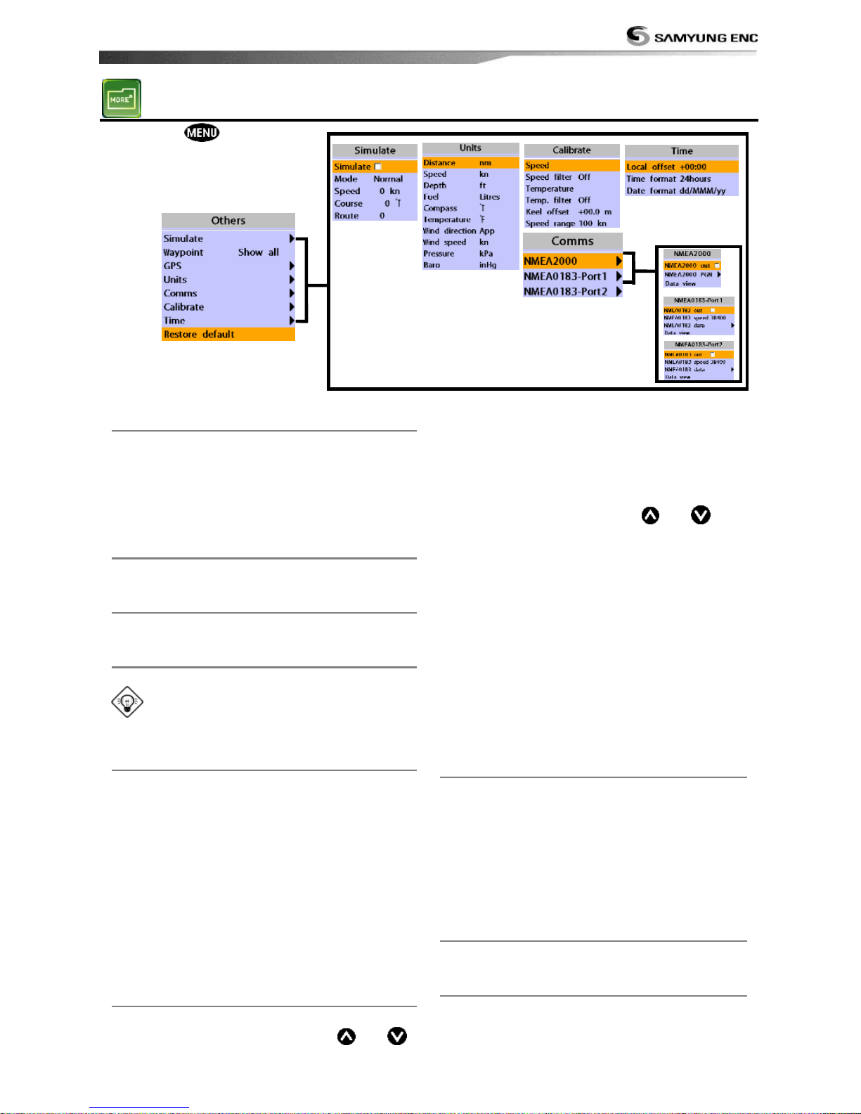
Installation and Operation Manual
61
4-9 Others
Press and then Others:
4-9-1 Simulate
Simulate :Turn the simulate mode on or off.
Mode : See 2-4 Simulate Mode.
Speed : The simulated boat speed to use.
Course : The simulated course over ground.
Route : The route to follow.
4-9-2 Waypoint
Select a way to display waypoints.
4-9-3 GPS
See 4-4 GPS Settings.
4-9-4 Units
Select a unit of each measure.
Tip: Requires a optional VHF receiver
with barometer connected: InHg or mB.
4-9-5 Comms
Use this feature when the unit is connected
to other marine electronics through any
compatible NMEA instrument.
NMEA0183/NMEA2000:This option to
transmit NMEA sentences to other marine
electronics. NMEA0183 and NMEA2000
interfaces are generally used with third party
marine electronics. Select a port (NMEA2000,
NMEA0183-Port 1 or NMEA0183-Port 2), a
communication speed and select a desired
output data.
4-9-6 Calibrate
Speed : Calibrate the boat speed. Travel at a
constant known speed and press
or
to calibrate the speed.
Speed filter : Set this option when removing
effects from waves and wind which affect the
speed of boat by averaging.
Temperature : Calibrate the water
temperature. Measure the water temperature
with thermometer then press
or to
calibrate the temperature.
Temperature filter : Set this option when
removing effects form water turbulence and
currents cause the water temperature to
fluctuate slightly.
Keel offset: A depth measured by a
transducer is depending on where the
transducer is installed. You can adjust the
depth of water in consideration of depth of
transducer installed in the water.
Speed range: Set a maximum speed of boat
that can be read in the unit.
4-9-7 Time
Local offset : The time information supplied
by the GPS satellites is in UTC (Universal
Time Coordinates). To read the correct time,
change the time of GPS chart plotter for
daylight saving time start and end.
Time format : Select the format of time.
Date format : Select the format of date.
4-9-8 Restore default
Returns every other setting to default.
4-9-9 Calendar
Provide a calendar function.
Page 62
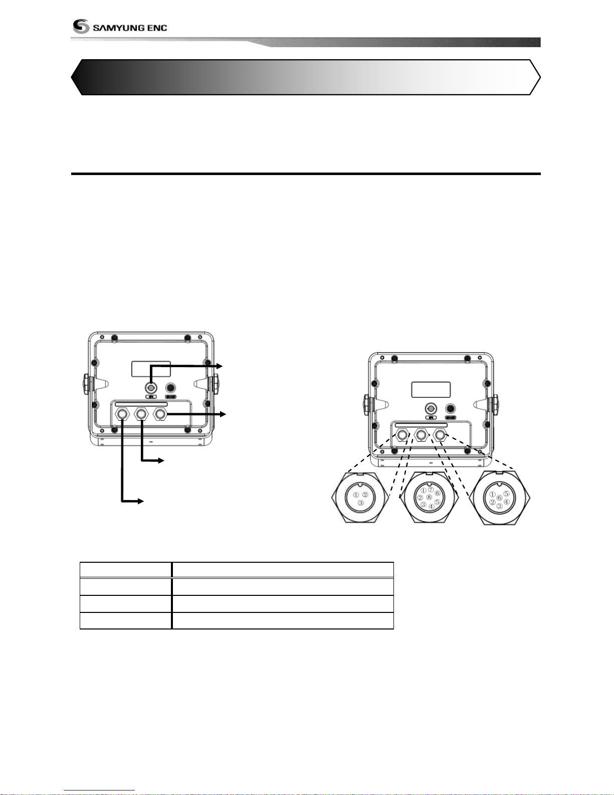
Installation and Operation Manual
62
Correct installation is important to the performance of the unit. It is vital to read the entire
installation section of this manual and the documentation that comes with the antenn a and any
other units before starting installation. For further information, please contact Samyung ENC.
5-1 Options and Accessories
Optional sensors and instruments
• External alarms
• GPS or DGPS antenna
• Sonar transducer
• Fuel sensors
• DSC VHF radio
• NMEA 2000: The chart plotter can display
engine data and.
• Other instruments: The chart plotter can
receive data from other instruments and
send data to other instruments by NMEA.
Connections
[Pin number]
[Power]
Pin No.
Detail
1
+ power input, 10 to 34 V DC
2
GROUND: - POWER INPUT
3
Not use
5 INSTALLATION
GPS
Sonar
-Temp.
-Speed
Radio
-NMEA 2000
-NMEA 0183 1,2
Power
Page 63
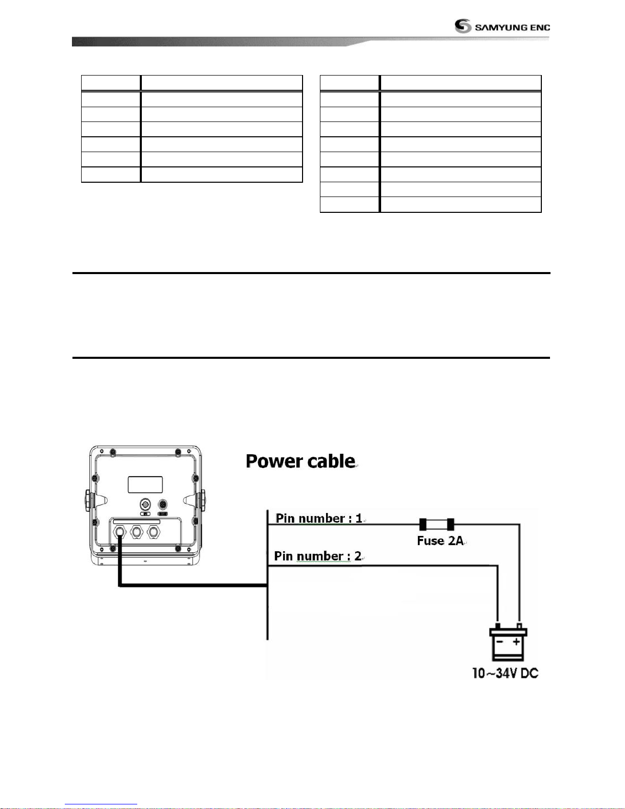
Installation and Operation Manual
63
[Sonar]
Pin No.
Detail
1
SONAR +
2
SONAR / TEMP. , GND
3
SPEED / + POWER SUPPLY
4
TEMP.
5
SONAR -
6
SONAR GND
[Radio]
Pin No.
Detail
1
+ 12 V DC
2
GND (COMMON)
3
NMEA 2000 H
4
NMEA 2000 L
5
NMEA 0183-1 OUTPUT
6
NMEA 0183-1 INPUT
7
NMEA 0183-2 OUTPUT
8
NMEA 0183-2 INPUT
5-2 Connections
The GPS chart plotter has connectors that are used to connect to the power supply, GPS
antenna and to NMEA devices such as VHF‟s AIS receivers, digital instruments and autopilots.
5-3 Power/data cable
Basic power
• Wire the display unit for basic power as below picture.
Page 64
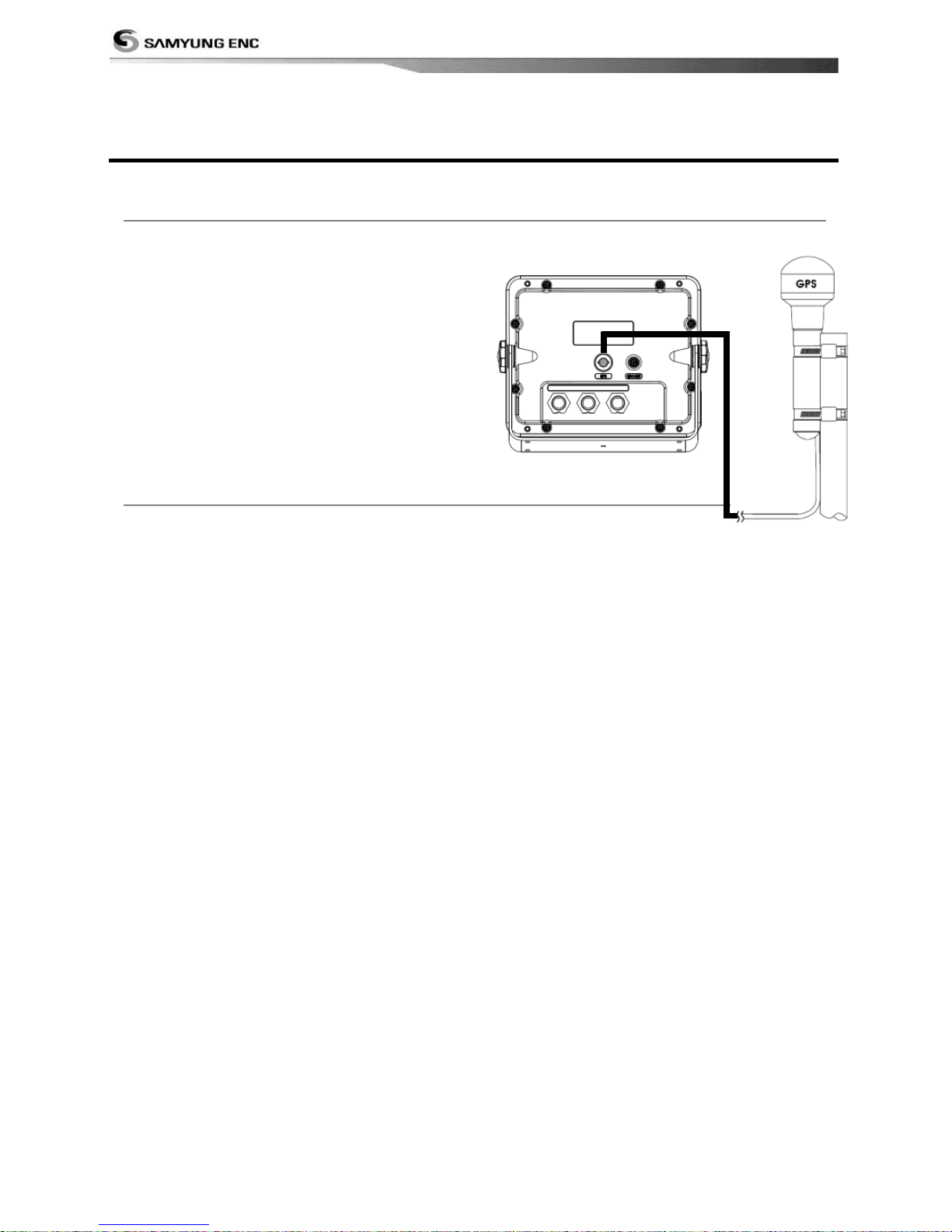
Installation and Operation Manual
64
5-4 GPS antenna
5-4-1 antenna
Installing a antenna
install the antenna and fit the antenna cable
back to the display unit. Follow the
instructions in the manual supplied with the
antenna. Fit an optional extension cable if
required.
During setup, configure the data for the
chosen antenna.
5-4-2 The antenna using NMEA
The chart plotter can receive the GPS data
from the compatible device (NMEA). The
chart plotter can connect several devices to
an external GPS.
• An optional differential beacon DGPS
antenna to give enhanced accuracy within
range of land based differential beacons in
areas where WAAS or EGNOS are not
available. Such a DGPS antenna has both a
GPS receiver and a beacon receiver, and it
automatically applies the beacon correction
to the GPS position.
To set the DGPS options(None or
WAAS/EGNOS):
Connect the GPS directly to the input. Set the
option. The new setting will be displayed if it
was successfully applied.
Note:
The chart plotter can apply the WAAS and
EGNOS DGPS corrections to any GPS
antenna.
For more information, contact Samyung ENC.
Page 65
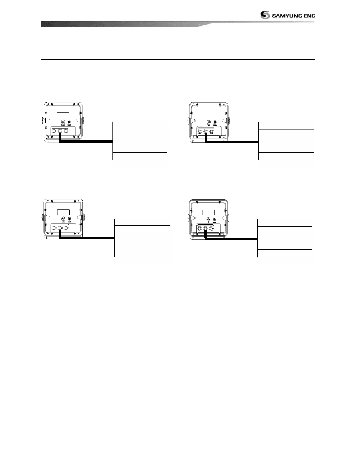
Installation and Operation Manual
65
5-5 NMEA 0183
The GPS chart plotter can be connected to
external devices with NMEA0183 and display
information such as followings.
• DSC VHF Radio
• GPS antenna(NMEA 0183)
• Navtex
• AIS receiver
DSC VHF radio
Fit and set up the optional DSC VHF radio as
above Pictures: NMEA 0183(1) IN and NMEA
0183(2) IN.
Other NMEA instruments
NMEA is an industry standard for
interconnecting instruments. The chart plotter
can be connected to other NMEA instruments.
Set up the optional NMEA instruments as
above pictures.
• The chart plotter can receive and display
depth, paddlewheel boat speed and water
temperature from an optional compatible
instrument.
• The chart plotter can receive data from an
optional compatible GPS or GPS/DGPS
source.
• The chart plotter can send GPS position and
other navigation data to an autopilot or
other instrument. An autopilot requires
APB, APA and VTG sentences
For information on sending NMEA data to the
instrument, contact Samyung ENC.
During setup to send NMEA data to other
instruments, set NMEA out and specify the
NMEA data to send.
Data cable
Pin number : 2 -
Pin number : 5 +
Output (1) NMEA 0183
Data cable
Pin number : 2 -
Pin number : 6 +
Input (1) NMEA 0183
Data cable
Pin number : 2 -
Pin number : 8 +
Input (2) NMEA 0183
Data cable
Pin number : 2 -
Pin number : 7 +
Output (2) NMEA 0183
Page 66
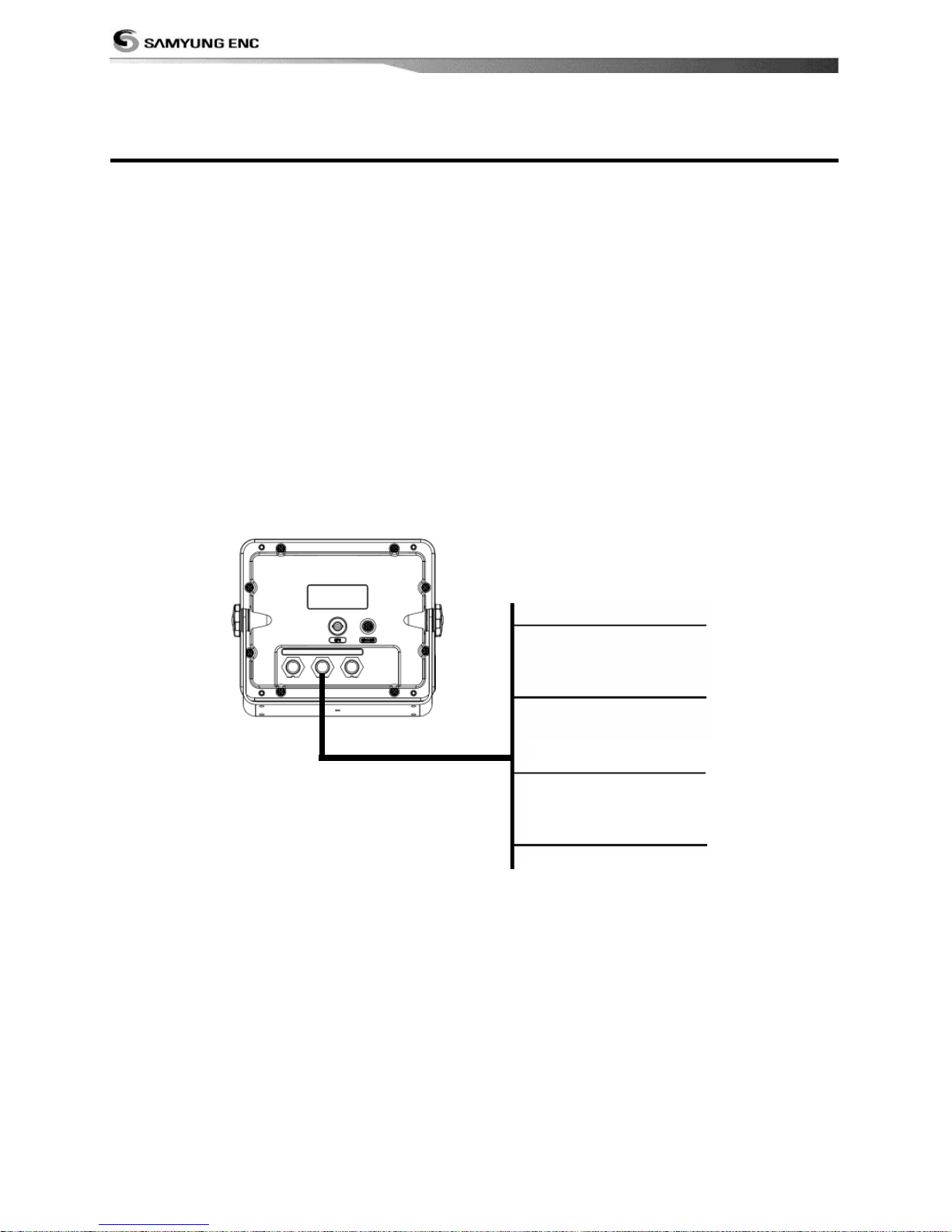
Installation and Operation Manual
66
5-6 NMEA 2000
NMEA 2000 interface standard was
introduced for communications network to
interconnect marine electronic equipments
such as navigation chart plotter, engine, tank
level sensor and others on vessels. The
standard is regulated by The National Marine
Electronics Association in USA.
The chart plotter can be connected to
external devices with NMEA2000 and display
information such as followings.
• Engines have fuel flow sensors, therefore
fuel sensors are not required.
• The chart plotter can receive and display
wind speed and direction from an optional
compatible wind instrument.
• The chart plotter can receive and display
depth from an optional depth instruments.
• The chart plotter can receive and display
boat speed and water temperature from a
paddlewheel sensor on a optional speed
instrument.
If connected display unit, use the cable
compatible with NMEA 2000 standard.
Data cable
Pin number : 3 H
Pin number : 4 L
NMEA 2000
Pin number : 1 DC +12V
Pin number : 2 DC -
Page 67
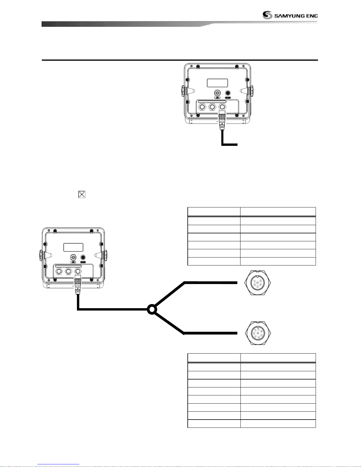
Installation and Operation Manual
67
5-7 Sonar Transducers
The transducer is a sensor that transmits and
receives sound waves into the water.
• Fit the sonar transducer supplied, following
the instructions in the Transducer
Installation Manual supplied with the chart
plotter.
• In case of installation of 50/200KH
transducer, water speed sensor and water
temperature sensor, an optional through
hull dual frequency sonar transducer and
through hull speed/temperature transducer
provide more enhanced performance.
Contact Samyung ENC for more
information.
• Connect the transducer to the chart plotter.
• At the system configuration window, set
Sonar to and set up the sonar options
If you use Y-Cable, the chart plotter can
display water temperature and water speed
from the compatible devices and receive and
display the depth from transducer.
To connect these instruments, please connect
the cable to the unit as the below picture.
Sonar cable
Temp./Speed
Transducer
Pin No.
Detail
1
TD 1
2
Shield
3 4
5
TD 2
6
Shield
Pin No.
Detail
1
Shield
2
Speed supply
3
GND (Shield)
4
TEMP.
5
6
Speed
7 8
Sonar Cable
Page 68

Installation and Operation Manual
68
5-8 Setup and test
1 Put a blanking cap on any unused connector on the back of the display unit. Ensure all
connectors are plugged in and the display unit is in place.
2 If the display unit is bracket mounted, adjust tilt and rotation for best viewing and hand
tighten the knob.
3 Insert any required NAVIONICS chart card.
4 Enter setup data to set up the chart plotter to your requirements and to set up any optional
sensors or instruments.
5 At the satellite display, check that it picks up GPS satellites. Wait for the GPS receiver to start
up and the GPS satellite to change to „Used in fix‟.
Page 69

Installation and Operation Manual
69
Thank you for purchasing an SAMYUNG ENC product. This product has been
thoroughly checked and is covered by the Samyung ENC’s warranty for defects in
materials and workmanship under normal use from the date of purchase.
This warranty provides for the free repair or replacement of defective parts from our
Samyung ENC authorized dealer.
In the event that your SAMYUNG ENC product needs service, please return your
SAMYUNG ENC product at your expense (shipping and insurance) to your Samyung
ENC distributor or SAMYUNG ENC authorized Service Centers. SAMYUNG ENC will, at
its discretion, repair or replace any defective products or its components at no cost to
you. This is your exclusive remedy for defective products
Exclusions: are specifically excluded from warranty;
1. Consumable items, including, but not limited to: fuses, impellers, impeller
bearings, impeller shafts are specif ically excluded from this warranty. . .
2. All costs associated with transducer replacement, other than the cost of the
transducer itself.
3. Routine system checkouts, alignment and calibration, seatrials, unless
required by replacement of defective parts.
Limited warranty: SAMYUNG ENC will not be responsible for equipment that has
been damaged or rendered defective:
1. as a result of incorrect installation, misuse, accident, water damage, abuse
or other external causes
2. by modification or service other than by SAMYUNG ENC or authorized
distributors, authorized Service Centers. SAMYUNG ENC will not be liable in
any event for any consequential or indirect loss or damage. Exceptions are
expressly set out in this warranty, SAMYUNG ENC makes no other
warranties, express or implied, including any implied warranties of
merchantability and fitness for a particular purpose. If any limitation or
exclusion of liability in this warranty is invalid and SAMYUNG ENC becomes
liable for loss or damage that would otherwise have been excluded, such
liability will be limited to the total amount actually paid by you for the
product.
3. if the serial number label on the unit has been removed, altered or
mutilated
Page 70

Installation and Operation Manual
70
Page 71

Installation and Operation Manual
71
 Loading...