

Samtron SC-726GXL Service Manual
COLOR MONITOR
SC-726GXL
-. -
’
SERWCEManua”
B
B
B
1. Precautions
2. Reference Information
3. Product Specifications
4. User Controls
5. Disassembly & Reassembly
6. Alignments & Adjustments
7. Troubleshooting
8. Exploded View & Parts List
9. Servicing Diagrams
9-l. Block Diagram
9-2. Wiring Diagram
9-3. PCB Layout and Electrical Parts List
9-4. Schematic Diagram
P
B
c
1 Precautions
Follow these safety, servicing and ESD precautions to prevent damage and to protect against potential
hazards such as electrical shock and X-rays.
.
l-1
Safety Precautions
l-l-l Warnings
For continued safety, do not attempt to
modify the circuit board.
Disconnect the AC power before servicing.
When the chassis is operating, semiconductor
heat sinks are potential shock hazards.
l-l-2
Servicing the High Voltage
System and Picture Tube
1.
When servicing the high voltage system,
remove the static charge by connecting a
10k
ohm resistor in series with an insulated wire
(such as a test probe) between the chassis and
the anode lead. (Disconnect the AC line cord
from the AC outlet.)
2.
Do not lift the picture tube by the neck.
3.
Handle the picture tube only when wearing
shatterproof goggles and after completely
discharging the high voltage anode.
l-l-3 X-Rays and High Voltage Limits
1.
Keep the high voltage below the specified
maximum level. Be sure all service personnel
are aware of the procedures and instructions
covering X-rays.
The only potential source of X-ray in current
solid state display monitors is the tube.
However, the picture tube does not emit
measurable X-ray radiation if the high
voltage is as specified in the fire and shock
hazard instruction. Only when high voltage is
excessive are X-rays capable of penetrating the
shell of the picture tube, including the lead in
glass material.
2.
It is essential that service technicians have an
accurate high voltage meter available at all
times. Check the calibration of this meter
periodically.
3.
High voltage should always be kept at the
rated value, no higher. Operation at high
voltages may cause failure of the picture tube
or high voltage circuitry and, also under
certain conditions, may produce X-rays in
excess of acceptable levels.
4.
When the high voltage regulator is operating
properly there is no possibility of an X-ray
problem. Test the brightness and use a meter
to monitor the high voltage each time a color
monitor comes in for service. Make sure the
high voltage does not exceed its specified
value and that it is regulating correctly.
5.
The picture tube is especially designed to
prohibit X-ray emissions. To ensure continued
X-ray protection, replace the picture tube only
with one that is the same or equivalent type as
the original. Carefully reinstall the picture tube
shields and mounting hardware; these also
provide X-ray protection.
6.
When troubleshooting a monitor with
excessively high voltage, avoid being
unnecessarily close to the monitor. Do not
operate the monitor longer than is necessary to
locate the cause of excessive voltage.
l-l-4 Fire and Shock Hazard
Before returning the monitor to the user, perform
the following safety checks:
1.
Inspect each lead dress to make certain that the
leads are not pinched or that hardware is not
lodged between the chassis and other metal
parts in the monitor.
2.
Inspect all protective devices such as
nonmetallic control knobs, insulating
materials, cabinet backs, adjustment and
compartment cover or shields, isolation
resistor-capacitor networks, mechanical
insulators, etc.
SC-726GXL
l-l
1 Precautions
Ir
.
11
J
/
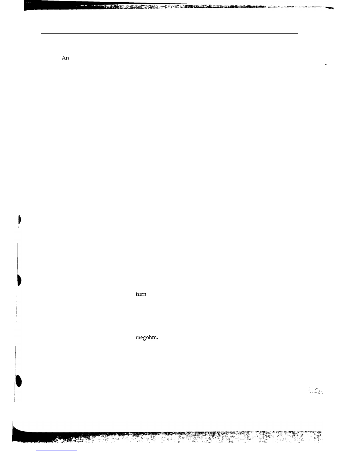
AC Voltmeter
To Exposed
To Known
Metal
Par%
Earth Ground
a.
b.
C.
d
e.
Use a SSVM or VOM with 1000 ohms
per-volt or higher sensitivity to measure
the AC voltage drop across the resistor (see
Figure l-1).
Connect the resistor to an exposed metal
part having a return path to the chassis
(metal cabinet, screw heads, knobs, shafts,
escutcheon, etc.) and measure the AC
voltage drop across the resistor.
Any reading of 5.25 Volt RMS (this
corresponds to 3.5 milliampere AC) or
more is excessive and indicates a potential
shock hazard. Correct the shock hazard
before returning the monitor to the user.
l-l-5 Product Safety Notices
Some electrical and mechanical parts have special
safety-related characteristics which are often not
evident from visual inspection. The protection
they give may not be obtained by replacing them
with components rated for higher voltage,
wattage, etc. Parts that have special safety
characteristics are identified by A on schematics
and parts lists. A substitute replacement that does
not have the same safety characteristics as the
recommended replacement part might create
shock, fire and / or other hazards. Product safety
is under review continuously and new
instructions are issued whenever appropriate.
,
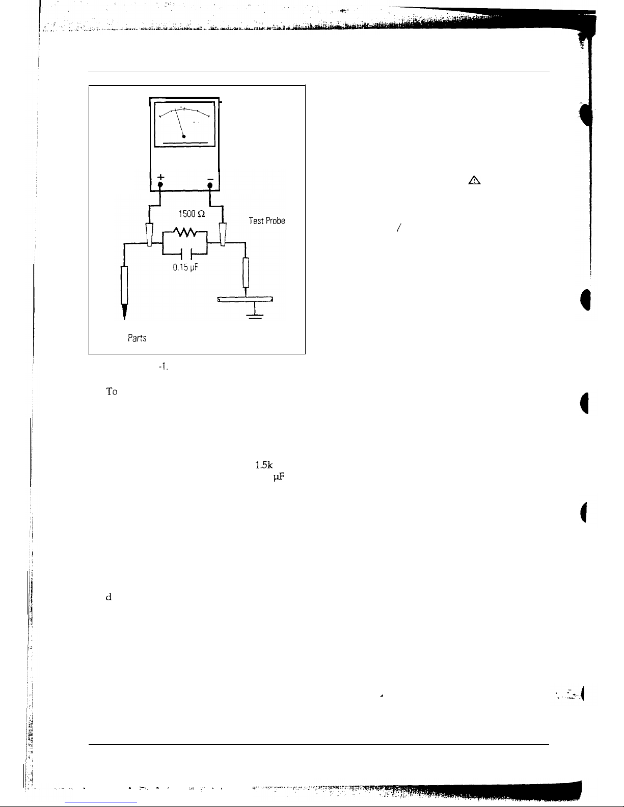
Figure1
-1.
leakage Current Test Circuit
3.
To be sure that no shock hazard exists, check
for leakage current in the following manner:
Plug the AC line cord directly into a 120
Volt AC outlet. (Do not use an isolation
transformer for this test)
Using two clip leads, connect a
1.5k
ohm,
10 watt resistor paralleled by a 0.15
fl
capacitor in series with an exposed metal
cabinet part and a known earth ground,
such as an electrical conduit or electrical
ground connected to an earth ground.
1-2
SC-726GXL
.
. ,-., - ,
,* :. . ,
1 Precautions
1-2 Servicing Precautions
Warning: AI-I electrolytic capacitor installed with the wrong polarity might explode.
-.
.
Caution: Before servicing instruments covered by this service manual and its supplements, read and follow
the Safety Precautions section of this manual.
Note: If unforeseen circumstances create conflict between the following servicing precautions and any of the
safety precautions, always follow the safety precautions.
1-2-1 General Servicing Precautions
8.
Always connect a test instrument’s ground
1.2.Servicing precautions are printed on the
cabinet. Follow them.
Always unplug the unit’s AC power cord from
the AC power source before attempting to: (a)
remove or reinstall any component or
assembly, (b) disconnect an electrical plug or
connector, (c) connect a test component in
parallel with an electrolytic capacitor.
lead to the instrument chassis ground before
connecting the positive lead; always remove
the instrument’s ground lead last.
3.
4.
5.
6.
7.
Some components are raised above the
printed circuit board for safety. An insulation
tube or tape is sometimes used. The internal
wiring is sometimes clamped to prevent
contact with thermally hot components.
Reinstall all such elements to their original
position.
After servicing, always check that the screws,
components and wiring have been correctly
reinstalled. Make sure that the portion around
the serviced part has not been damaged.
Check the insulation between the blades of the
AC plug and accessible conductive parts
(examples: metal panels, input terminals and
earphone jacks).
Insulation Checking Procedure: Disconnect the
power cord from the AC source and turn the
power switch ON. Connect an insulation
resistance meter (500 V) to the blades of the
AC plug.
The insulation resistance between each blade
of the AC plug and accessible conductive parts
(see above) should be greater than 1
megohm.
Never defeat any of the B+ voltage interlocks.
Do not apply AC power to the unit (or any of
its assemblies) unless all solid-state heat sinks
are correctly installed.
SC-726GXL
l-3
1 Precautions
-
l-3 Electrostatically Sensitive Devices (ESD) Precautions
Some semiconductor (solid state) devices can be easily damaged by static electricity. Such components
commonly are called Electrostatically Sensitive Devices (ESD). Examples of typical ESD devices are
integrated circuits and some field-effect transistors. The following techniques will reduce the incidence of
component damage caused by static electricity.
1.
2.
3.
4.
5.
6.
7.
Immediately before handling any
semiconductor components or assemblies,
drain the electrostatic charge from your body
by touching a known earth ground.
Alternatively, wear a
dischar,tig
wrist-strap
device. To avoid a shock hazard, be sure to
remove the wrist strap before applying power
to the monitor.
After removing an ESD-equipped assembly,
place it on a conductive surface such as
aluminum foil to prevent accumulation of
electrostatic charge.
Do not use freon-propelled chemicals. These
can generate electrical charges sufficient to
damage
ESDs.
Use only a grounded-tip soldering iron to
solder or desolder
ESDs.
8.
Minimize body motions when handling
unpackaged replacement
ESDs.
Motions such as brushing clothes together, or
lifting your foot from a carpeted floor can
generate enough static electricity to damage an
ESD.
9.
A
marks parts for
ESDs
on schematic
diagrams and electrical parts list.
Use only an anti-static solder removal device.
Some solder removal devices not classified as
“antistatic” can generate electrical charges
sufficient to damage
ESDs.
Do not remove a replacement ESD from its
protective package until you are ready to
install it. Most replacement
ESDs
are packaged
with leads that are electrically shorted
together by conductive foam, aluminum foil
or other conductive materials.
Immediately before removing the protective
material from the leads of a replacement ESD,
touch the protective material to the chassis or
circuit assembly into which the device will be
installed.
Caution: Be sure no power is applied to the
chassis or circuit and observe all other safety
precautions.
1-4
SC-726GXL
- =__
-’
.c
2
Reference Information
2-l
Eming
Chart
=.
-
This
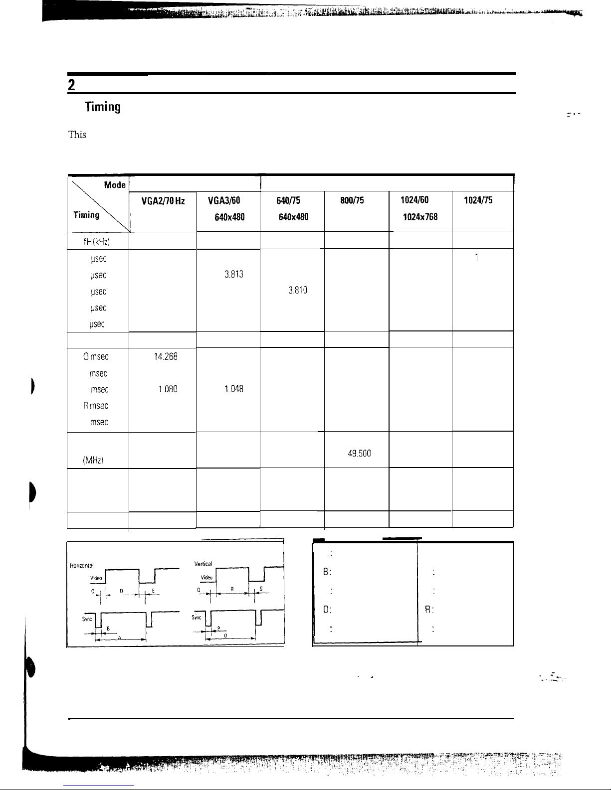
section of the service manual describes the timing that the computer industry recognizes as standard
for computer-generated video signals.
Table 2-l. Timing Chart
fH (kHz)
A
psec
B
psec
C
psec
D
psec
E
psec
fv (Hz)
0
msec
P
msec
Q
msec
R msec
S
msec
Clock
Frequency
@J-W
Polarity
H.Sync
V. Sync
Remark
IBM
VGAzf70
Hz
720x400
VGA3l60 Hz
640x480
640/Z
Hz
640x480
31.469
31.469
37.500
31.777
31.778
26.667
3.813
3.813
2.032
1.907
1.907
3.810
25.422
25.422
20.317
0.636
0.636
0.508
70.087
59.940
75.000
14.268
16.683
13.333
0.064
0.064
0.080
1.080
i ,048
0.427
12.711
15.253
12.800
0.413
0.318
0.027
28.322
25.175
31.500
Positive
Negative
Separate
Negative
Negative
Separate
Negative
Negative
Separate
Separate Sync
VESA
aoop5
Hz
800x600
46.875
21.333
1.616
3.232
16.162
0.323
75.000
13.333
0.064
0.448
12.800
0.021
49.500
Positive
Positive
Separate
1024/60
Hz
1024x768
1024P5 Hz
1024x768
48.363
60 023
20.677
i
6.660
2.092
1.219
2.462
2.235
15.754 13.003
0.369
0.203
60.004 75.029
16.666
13.328
0.124 0.050
0.600 0.466
15.880 12.795
0.062 0.017
65.000 78.750
Negative
Negative
Separate
Positive
Positive
Separate
A : Line time total
6 :
Sync width
C : Back porch
0 :
Active time
E : Front porch
0 : Frame time total
P : Sync width
Q : Back porch
R :
Active time
S : Front porch
SC-726GXL
2-l
2 Reference Information
Mode
\
Timing
\
fH (kHz)
A
usec
B
psec
C psec
Cl usec
E
usec
fv (Hz)
0 msec
P
msec
Cl msec
R msec
S
msec
Clock
Frequency
(MHz)
Polarity
HSync
V.Syrlc
Remark
-
VESA
128OP5
Hz
1280x1024
79.976
12.504
1.067
1.837
9.481
0.119
75.025
13.329
0.038
0.475
12.804
0.013
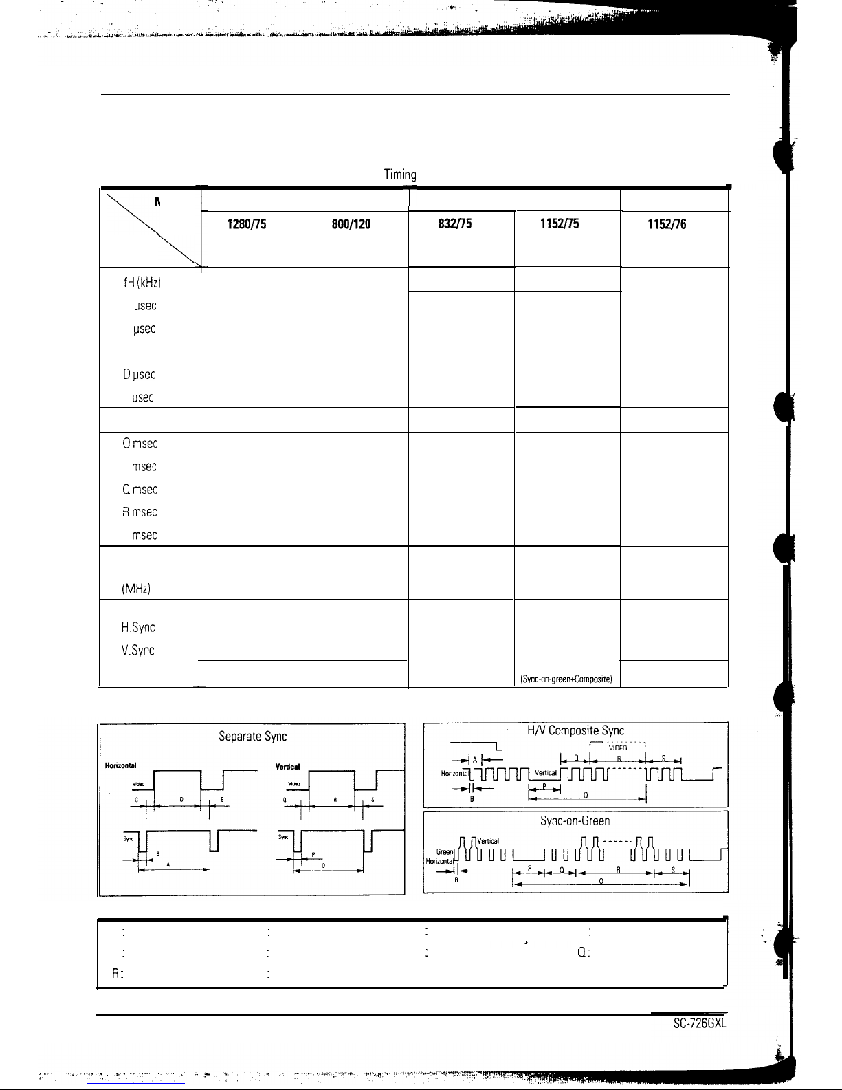
Table 2-l.
Timi
SIGMA
800/120
Hz
800x600
76.923
13.000
1.100
1.400
10.000
0.500
120.192
8.320
0.195
0.247
7.800
0.078
135.000
Positive
Positive
Separate
80.000
Negative
Negative
Separate
w
T
Chart Continued
Apple Mac.
WI75
Hz
832x624
49.726
20.110
1.117
3.910
14.524
0.559
74.551
13.414
0.060
0.784
12.549
0.020
57.284
Negative
Negative
Separate
1152P5
Hz
1152x870
68.681
14.560
1.280
1.440
11.520
0.320
75.062
13.322
0.044
0.568
12.667
0.044
100.000
Negative
Negative
Composite
ISync-on-green+Composlte)
T
SUN
lWJ76
Hz
1152x900
71.713
13.945
0.909
1.970
10.913
0.152
76.047
13.150
0.112
0.460
12.550
0.028
105.560
Negative/Positive
Negative/Positive
Separate
A : Line time total
B : Sync width
C : Back porch
D : Active time
E : Front porch
R :
Active time
0 : Frame time total
S : Front porch
P : Sync width
Cl :
Back porch
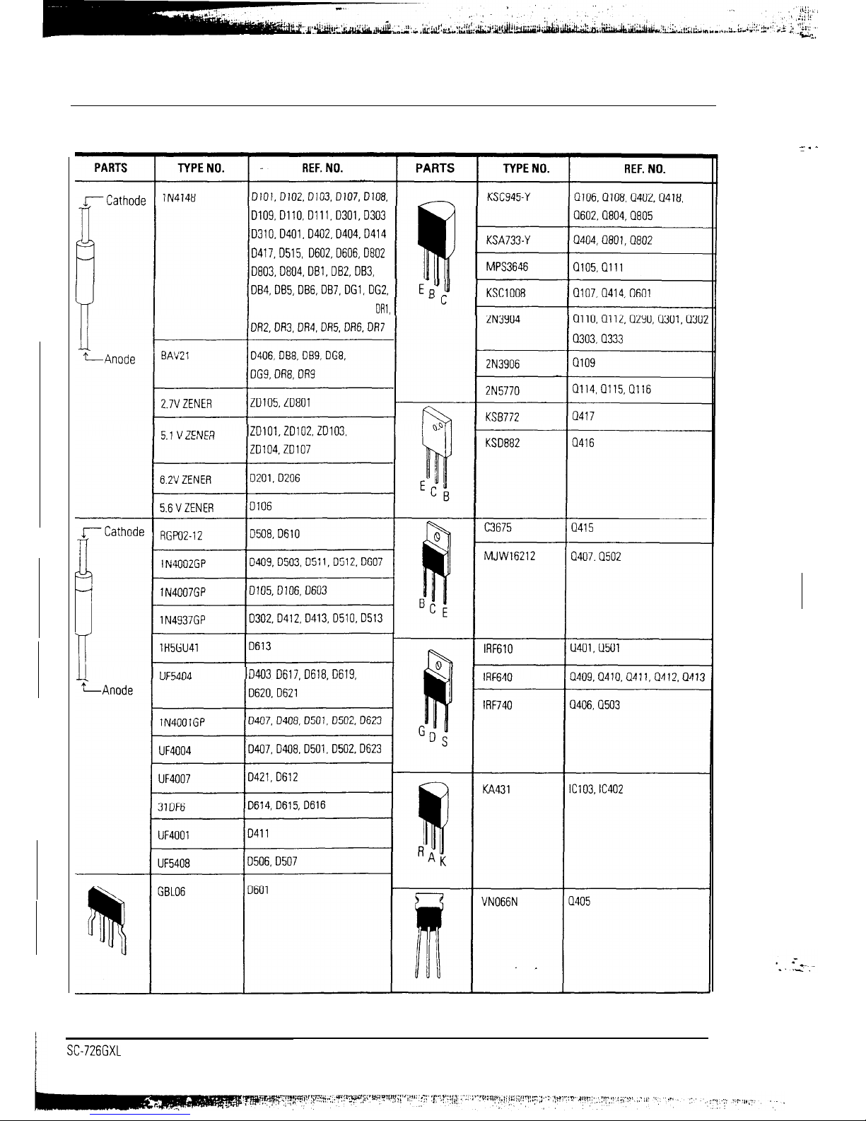
2 Reference Information
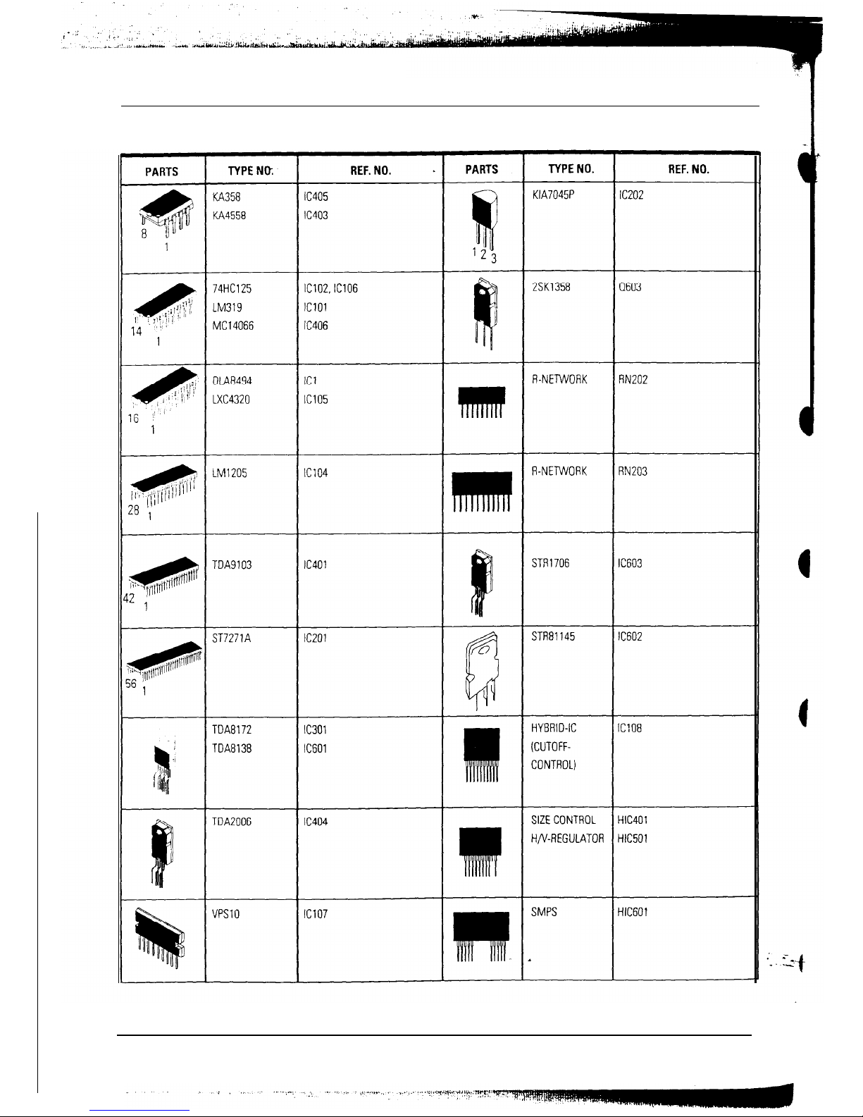
2-2 Semiconductor lead Identification
D109,D110,0111.D301,D303
D310.D401.D402.D404,D414
D417.0515, D602,D606,0802
D803,D804,DBl,DBZ,DB3,
DG3, DG4, DG5, DG6, DG7,
DAl,
ZD101,20102.20103.
D403 D617,0618.D619,
=.
-
SC726GXL
2-3
2 Reference Information
2-2 Semiconductor Lead Identification
2-4
SC-726GXL
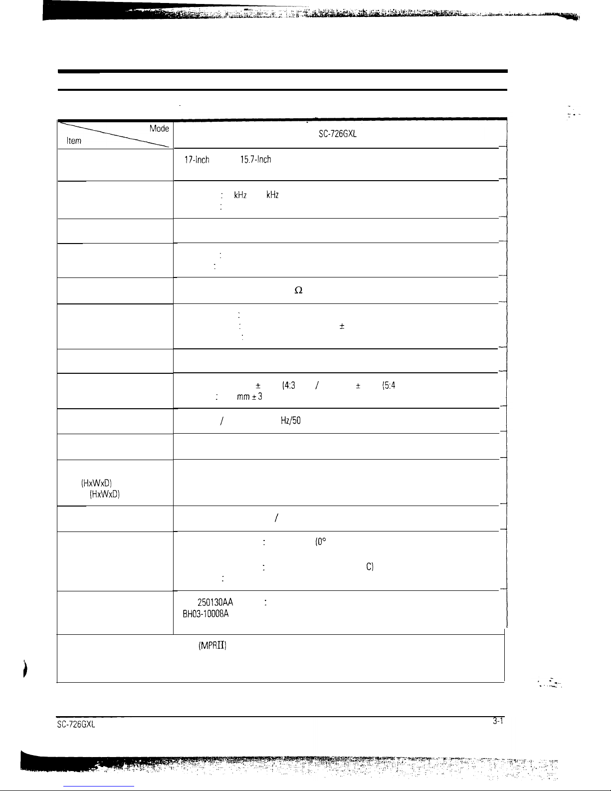
3 Product Specifications
3-1 Specifications
Picture Tube:
Scanning Frequency
Display Colors Analog input
Maximum Resolution
Input Video Signal
Input Sync Signal
Maximum Pixel Clock
Active Display
Input Voltage
Power Consumption
Dimensions
Unit
(HxWxD)
Carton (HxWxD)
Weight
Environmental Considerations
CRT Code No.
17-Inch
(43 cm):
15.7-Inch
(40 cm) Visual, Full square/flat face tube, 90” deflection,
0.26 mm Dot pitch, Semi-tint, Non-glare, Antistatic silica coating, lnvar shadow mask
Horizontal : 30
kHz
to 85
kHz
(Automatic)
Vertical
:
50 Hz to 120 Hz (Automatic)
Unlimited Colors
Horizontal : 1280 Dots
Vertical : 1024 Lines
Analog 0.714 Vp-p Positive at 75 Q Terminated
Separate Sync : TTL level Positive/Negative
Sync-on-Green: Composite Sync 0.286 Vp-p ? 5 %/Negative (Video on Vp-p positive)
Composite Sync : TTL level Positive/Negative
135 MHz
Horizontal 306 mm + 3 mm
(4:3
ratio) / 287.5 mm k 3 mm
(54
Ratio)
Vertical : 230
mm_+3
mm
AC 90-l 32 / 198-264 Volt, 60 Hz/50 Hz+3 Hz
120 Watt (Max)
16.5 x 16.9 x 17.3 Inches (420 x 428 x 439 mm)
21.2 x 21.5 x 21.9 Inches (538 x 545 x 554 mm)
Net/Gross: 41.9 Lbs (19 kg) / 48.5 Lbs (22 kg)
Operating Temperature : 32°F to 104°F
(0’
C to 40” C)
Humidity : 10 % to 80 %
Storage Temperature
:
-4°F to 113°F (-20” c to 45”
C)
Humidity : 5 % to 95 %
897
25013OAA
(Hitachi) : ASC Coating
BH03-10008A (Samsung): ASC Coating
l SC-726GXL complies with SWEDAC (MPRII) recommendations for reduced electrostatic fields.
l Designs and specifications are subject to change without prior notice.
J
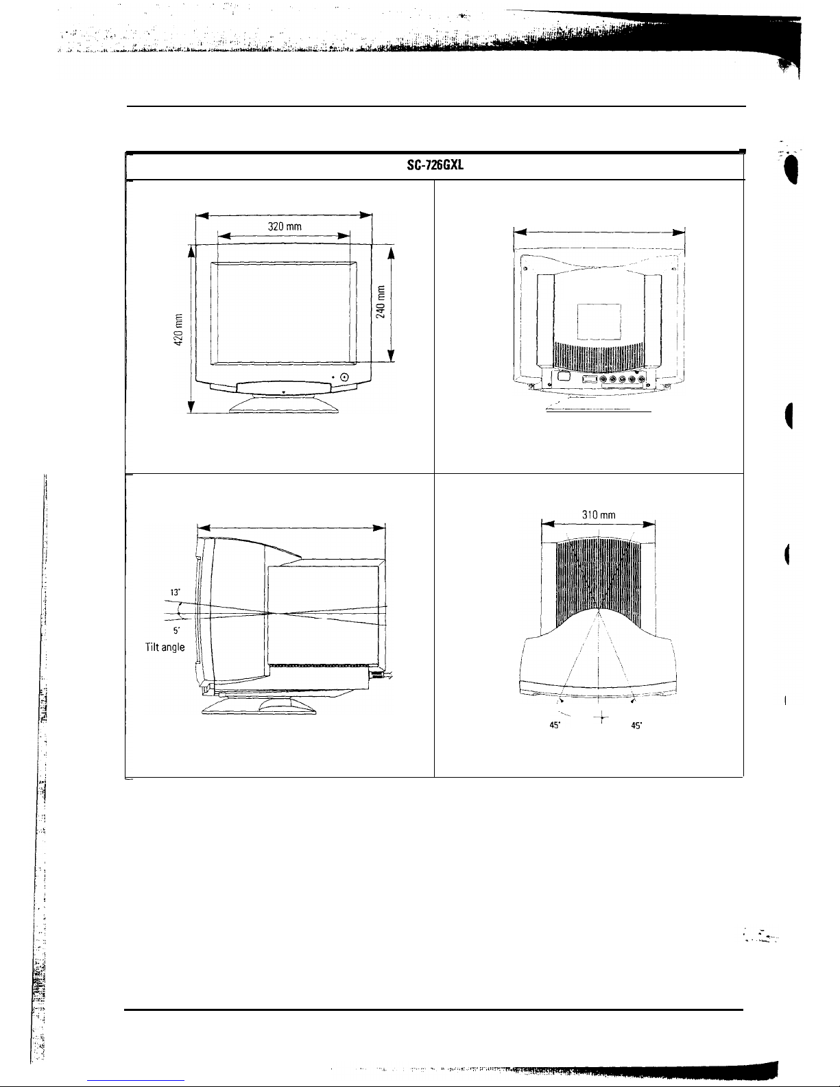
3 Product Specifications
3-2 Dimensions
SC-726GXL
428 mm
428 mm
___----
--
.-__
__
:
,_------~_
439 mm
451“- -f- 45’
Swivel angle
.
3-2
SC-726GXL
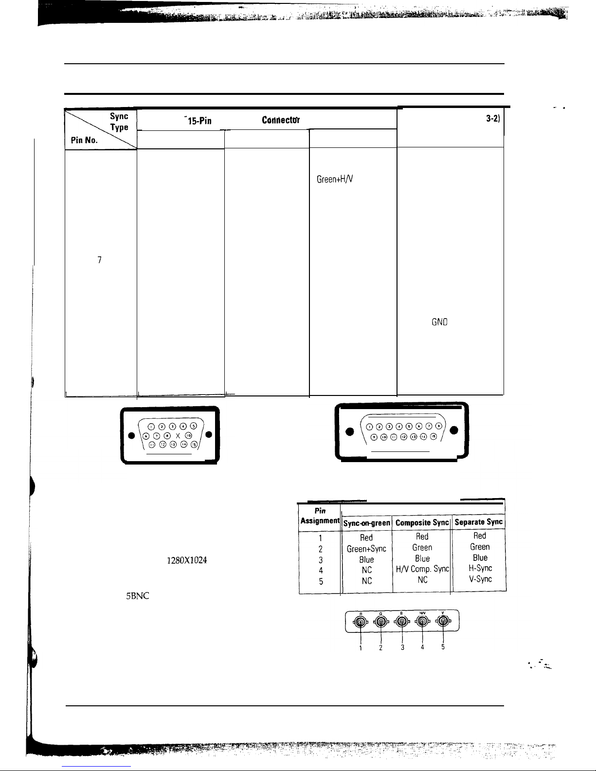
3 Product Specifications
3-3 Pin Assignments
1
Red
2
Green
3
Blue
4
GND
5
DDC Return
6
GND-R
7
GND-G
8
GND-B
9
Reserved
10
GND-Sync/Self-Raster
11
GND
12
DDC Data
13
H-Sync
14
V-Sync
15
DDC Clock
_
15-Pin Signal Cable Corldectm (Figure 3-1)
Separate
-
Figure 3-l. Male
Type
Composite
Red
Green
Blue
GND
DDC Return
GND-R
GND-G
GND-B
Reserved
GND-Sync/Self-Raster
GND
DDC Data
H/V-Sync
Not Used
DDC Clock
BNC Connectors
BNC connectors are used with coaxial cable for
improved signal transmission. Better signal
transmission becomes critical at high frequencies
such as those required for
1280X1024
resolution.Most
video boards that operate at 1280X1024 resolution
recommend using coaxial cable with BNC
connectors.The
5BNC
connectors on the rear of
the
monitor can accept Red, Green, and Blue video.
Composite sync can be applied separately, or
combined with the Green video signal (commonly
referred to as “composite sync-on-green”).
If composite sync-on-green is used, then only 3 of the
5 BNC connectors are used. The connectors are
labeled accordingly.
Sync
On
Green
Red
GreentH/V
Sync
Blue
GND
DDC Return
GND-R
GND-G
GND-B
Reserved
GND-Sync/Self-Raster
GND
DDC Data
Not Used
Not Used
DDC Clock
Cable Adapter (Figure
3-2)
Macintosh
GND-R
Red
H/V Sync
Sense 0
Green
GND-G
Sense 1
Reserved
Blue
Sense 2
GNO
V-Sync
GND-B
GND
H-Sync
Figure 3-2. Male Type
1
Signals
Figure 3-3. BNC Signal Input Type
SC-726GXL
3-3
_. .
* --_.
.’ ._
4 User Controls
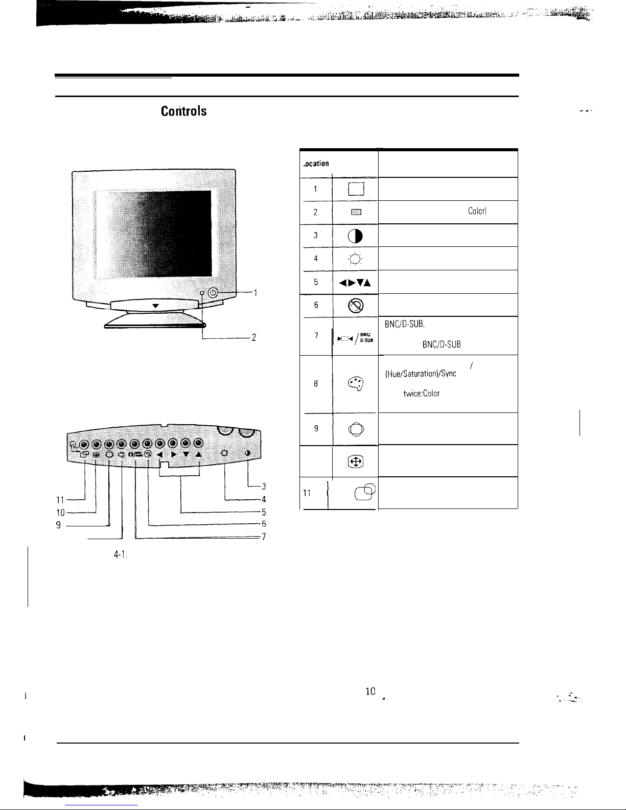
4-l Front View and
Cotitrols
4-l-l SC-726GXL Front View
9
8-
Figure
4-l.
SC-726GXL Front Control Panel
User Adjustments
Directions for making User Adjustments are the
same as those given in Chapter 6, Alignments and
Adjustments, under the directions for “Without
microcomputer control jig.”
_. . .
4-l-2 SC-726GXL Front Control Panel
.ocation
Symbol
10
633
” /
0
On Screen Display
Description
Power Button (Push)
Power Indicator LED (Dual
Color1
Contrast Control
Brightness Control
Adjustment Controls
Degauss Button
BNC/D-SUB,
Recall Button
Push once: Recall
Push twice:
BNC/D-SUB
Color Temperature Control / Color Control
(Hue/Saturation)/Sync Select
Push Once: Color Temperature Control
Push twice:Color Control (Hue/Saturation)
Push three times: Sync Select
G/D (Geometric Distortion)
Push once: Pincushion /Trapezoid
Push twice: Parallelogram /Tilt
Size and Information
Push once: Size (Horizontal /Vertical)
Push twice: Information
Position and Modes
Push once: Position (Horizontal /Vertical)
Push twice: User and Preset Modes
The monitor features an On Screen Display (OSD)
that shows information about the display settings.
The OSD appears on the screen when you select a
function button. The OSD shows the name, range
and current setting of the control function.
In addition, the OSD shows the current input
signal frequency and the list of user and factory
preset timings. The OSD remains active for
approximately 1C seconds after completion of any
A
adjustment.
I
SC-726GXL
4-1
qm
4 User Controls
Note
I:
Note 2
:
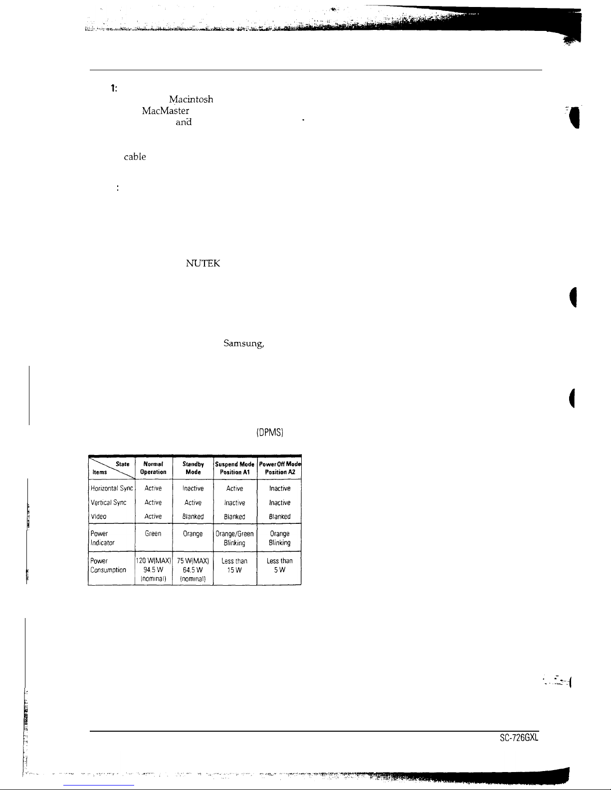
This monitor requires a cable adapter for
use with a
R/iacintosh
computer.
The MacMaster Cable Adapter supports
all monitors
an?I
all Macintosh, Centris,
1
Quadra, Duo Dock, and Power Macintosh
computers. If you do not already have a
cabIe
adapter, check with your computer
dealer.
The monitor automatically returns to the
normal operation state when horizontal
and vertical sync returns. This occurs
when you move your mouse or press a
key on your keyboard.
This monitor is EPA Energy Star
compliant and
NLTTEK
compliant when
used with a computer equipped with
VESA DPMS function. If your computer
system cannot support a display power
management function, you may purchase
an optional DPMS software program to
take advantage of the power saving
function. Please contact
Samsung,
or your
dealer, for more information.
For Energy conservation, turn your
monitor OFF when the monitor is not
needed, or when leaving it unattended for
long periods.
Table 4-l Display Power Management Signaling
(DPMS)
Standard
4-2
SC-726GXL
5 Disassembly and Reassembly
This section of the service manual describes the disassembly and reassembly procedures for
SC-726GXL monitor.
.
WARNING: This monitor contains electrostatically sensitive devices. Use caution when handling any components.
5-l Disassembly
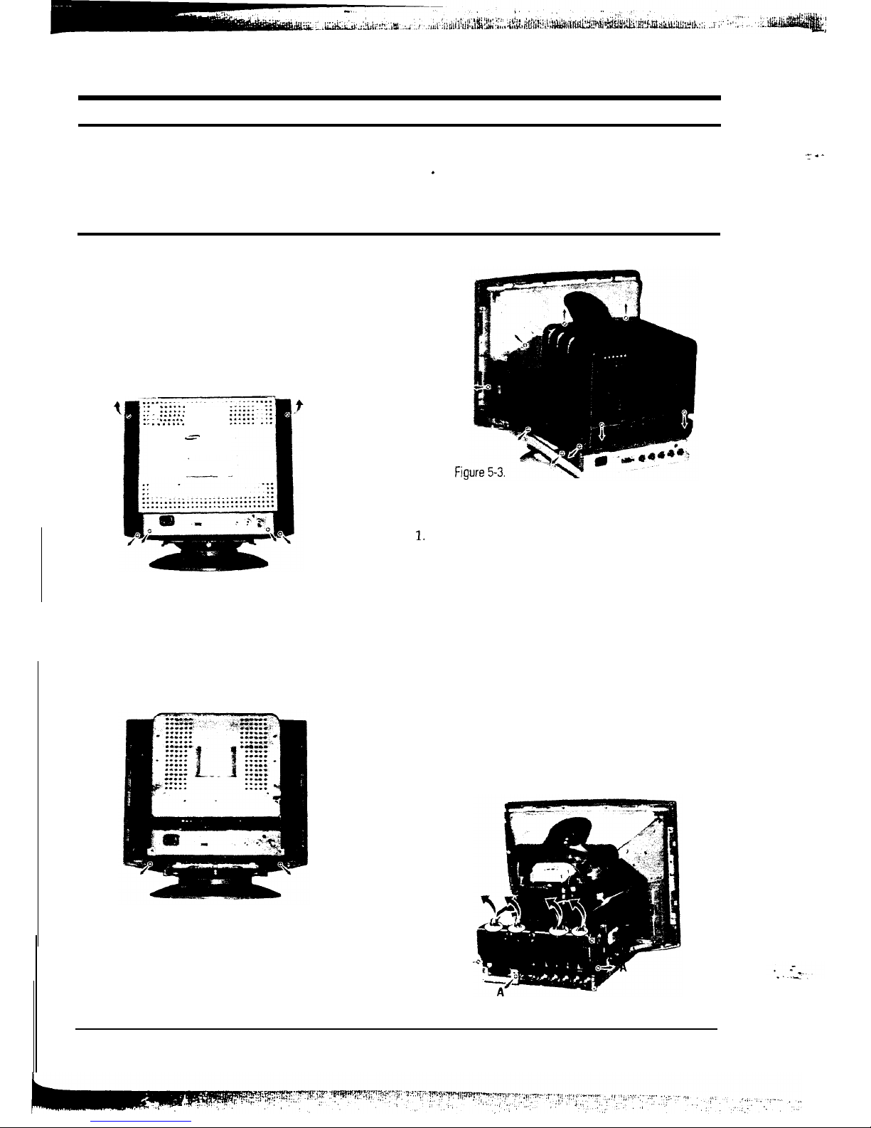
5-l-l Removing the Cabinet
1. With a pad underneath it, stand the monitor on
its front with the screen facing downward and
the base closest to you. Make sure nothing will
damage the screen.
2. Working from the back of the monitor, remove
the six
screws.
t
:: ::::::
,r ._....
.-- . . . . . .
-. . . ...*
-_
_~
.-
Figure 5-1.
3. Tilt the cabinet away to release the three tabs
and pull it up and away from the monitor.
4. Remove the two screws from the cabinet
bottom. Lift the bottom off and away from the
monitor.
Fig
5-l-2 Removing the Video PCB
1.
2.
3.
4.
5.
Remove the four connectors:
Sync
Power
Video out
Color controller
Remove the three screws (A) holding the Video
PCB Ass’y onto the main PCB Ass’y and slide it
off.
Remove the six screws on the Video PCB Shield
and lift the top off.
Remove the one screw holding the Video PCB
Shield bottom and left the PCB out.
Set Video PCB on a smooth, level surface which
is protected from static electricity.
Figure
5-2.
5. Remove the 14 screws from around the metal
shielding. Lift the shielding up and away from
the CRT.
A-
Figure
5-4.
SC-726GXL
5-1
-_’ .
-
5 Disassembly and Reassembly
5-l-3 Removing the Main PCB
1. If you have not already done so, remove the
Video PCB.
-
2. Remove the CRT PCB.
3. Remove the two screws holding the main PCB
Ass’y to the front cover.
Pull Off
Figure 5-5.
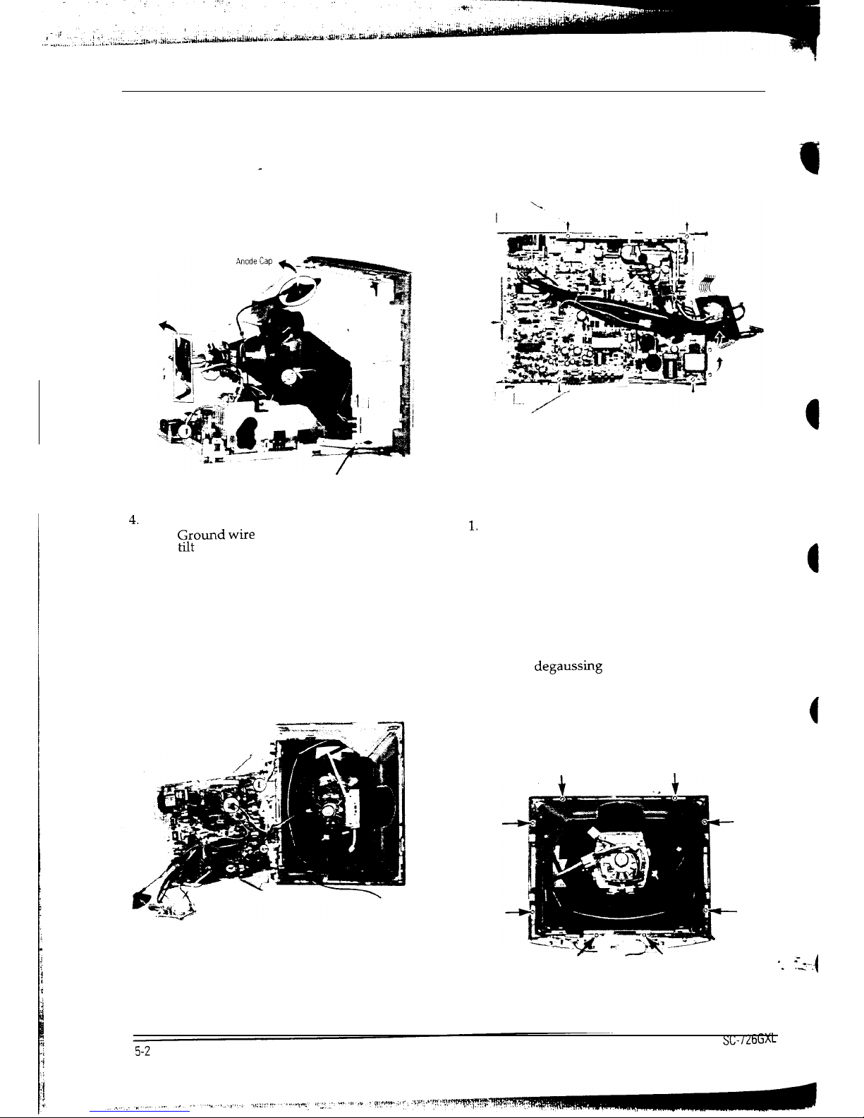
4.
Remove the accessible connectors:
%Ound
wire
Degaussing coil
Anode cap
5. Lift the Main PCB Ass’y up slightly and tilt it
away from the CRT so that you can reach and
remove the following connectors:
Horizontal deflection yoke
Vertical deflection yoke
Controller
Function key
Figure 5-6.
6. Pull the Main PCB Ass’y away from the CRT.
7. Remove the eight screws holding the main PCB
8.
in the PCB Bracket, remove the power shaft and
lift the Main PCB out.
Set main PCB on a smooth, level surface which
is protected from static electricity.
Figure 5-7
5-l-4 Removing the CRT
Caution: Do not touch the Anode
1.
2.
3.
4.
5.
6.
If you have not already done so, remove the
Main PCB.
Remove the eight screws securing the CRT
Bracket Assembly.
Release the grounding wire clips from the
grounding prongs on the CRT Bracket Ass’y.
Lift the CRT Bracket Ass’y up and away from
the CRT. The CRT Bracket Ass’y includes the
bracket, degaussmg coil and tilt coil.
Remove the screw at each of the four comers of
the CRT. This releases the CRT and the CRT
Ground Ass’y. Lift the CRT tube (do not lift by
(
the tube neck) out of the Front Cover Assembly.
Remove the CRT Ground Ass’y.
** :_=--.-(
Figure 5-8.
5 Disassembly and Reassembly
5-2 Reassembly
With the CRT facing
downw-ard
on a protective pad, use the steps that follow to reassemble the monitor.
5-Z-l Replacing the CRT
1. With the front cover assembly lying face down
on a protective pad, position the CRT so that the
corner metal tabs fit properly in the Front
Cover.
2. Position the CRT Ground Ass’y around the CRT
and secure it and the CRT at each of the four
corners with the CRT screws. Make sure the
grounding wire clips are accessible.
3. Position the CRT Bracket Ass’y around the CRT
and replace the eight screws. Attach the
grounding wire clips onto the grounding
prongs on the CRT Bracket Ass’y.
5-2-2 Replacing the Video PCB
1. Place the Video PCB in the Video Shield bottom
and replace the one screw that holds it in place.
2. Position the Video Shield top on the bottom and
replace the six screws.
3. Slide the Video PCB Ass’y onto the Main PCB
Ass’y and secure it with two screws.
4. Reconnect the four connectors:
Color controller
Video out
Power
Sync
5-2-3 Replacing the Main PCB
1. Set the Main PCB in the PCB bracket and secure
it with eight screws.
2. Hold the Main PCB Ass’y close to the CRT as
shown in figure 5-7 and reconnect the following
connectors:
Function key
Controller
Vertical deflection yoke
Horizontal deflection yoke
Anode cap
Degaussing coil
Tilt control
Ground coil
3. ‘Replace the CRT PCB
4. Position the Main PCB Ass’y on the front cover
(see figure 5-5) and hold it secure with two
screws.
5. If you have not already done so, replace the
Video PCB.
5-2-4 Replacing the Cabinet
Position the metal shielding around the CRT.
If so equipped, make sure the tabs are snapped
in place. Replace the 14 screws. See figure 5-3.
Position the cabinet bottom and replace the two
screws (see figure 5-2).
Position the cabinet top making sure the three
tabs along the upper front edge are properly
snapped in place. Replace the six screws.
Set the monitor on its base and make sure that
the CRT screen was not scratched or otherwise
damaged.
6 Alignments and Adjustments
This section of the service manual explains how to control the linearity, raster, size, position, pincushion,
parallelogram, trapezoid, and
pinbalance.
Additionally, this section describes how to use the micom control
jig to make the adjustments.
6-l
Adjustment Conditions
Caution: Changes made without the micom jig are saved only to the user mode settings. As such, the settings are not permanently
stored and may be inadvertently deleted by the user.
Direction
When servicing, always face the monitor toward
the East and, whenever possible, use magnetic
field isolation such as a helmholtz field around the
monitor.
Caution: Other electrical equipment may cause
external magnetic fields.
During servicing, use an external degaussing coil
to limit magnetic build up, If an external
degaussmg coil is not available, use the internal
degaussing circuit, but not more than once per
minute.
After finishing all adjustments, test the monitor in
all directions. If, for example, the monitor does not
meet adjustment specifications when facing in a
northerly direction, face the monitor eastward
again and readjust the monitor to the smallest
error possible within a reasonable time limit. Test
the unit again in all directions. If the monitor again
fails to meet specifications in a non-easterly
direction, contact your region’s main service center
for possible CRT replacement.
Testing and Burn-in Mode
For testing and bum-in, remove the signal cable
from the monitor. Power on the monitor and
warm it up. Use the bum-in mode to age
the monitor.
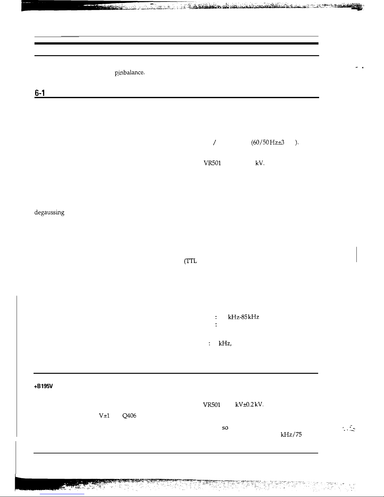
Power Supply Voltage
AC 90-132 / 198-264 Volt
(60/50 Hz&3
Hz
).
High Voltage Control
Adjust
VR501
to 26 kVr0.2
kV.
Warm-Up Time
The display must be on for 30 minutes before
starting alignment. Warm-up time is especially
critical in color temperature and white balance
adjustments.
Signal
Video analog 0.714 Vp-p positive at 75 ohm
terminated.
Sync: Separate/composite
(TTL
level negative/positive).
Sync-on-Green:
Composite sync 0.286 Vp-p negative
(Video 0.714 Vp-p positive).
Scanning Frequency
Horizontal
:
30
kHz-85 kHz
(Automatic).
Vertical
:
50 Hz-120 Hz (Automatic).
Unless otherwise specified, adjust to 1024x768
mode (H : 60
kHz,
V: 75 Hz) signals. Refer to
table 2-l on pages 2-l and 2-2.
6-2 Prepare Main PCB for Adjustment
+B 195V
Line Adjustment
No beam, Contrast: Minimum,
Brightness: Minimum.
Adjust VR601 to DC
1
and GND.
High Voltage Adjustment
No beam, Contrast: Minimum,
Brightness: Minimum
Adjust
VR501
to 26
kVa.2 kV.
_. .
95
V+l
V at
Q406
heat sink
Center Raster
Adjust SW401 so that the back raster comes to the
center when you apply a signal of 60
kHz/75
Hz.
‘ =*.
. . .i
SC-726GXL
6-l
6 Alignments and Adjustments
-
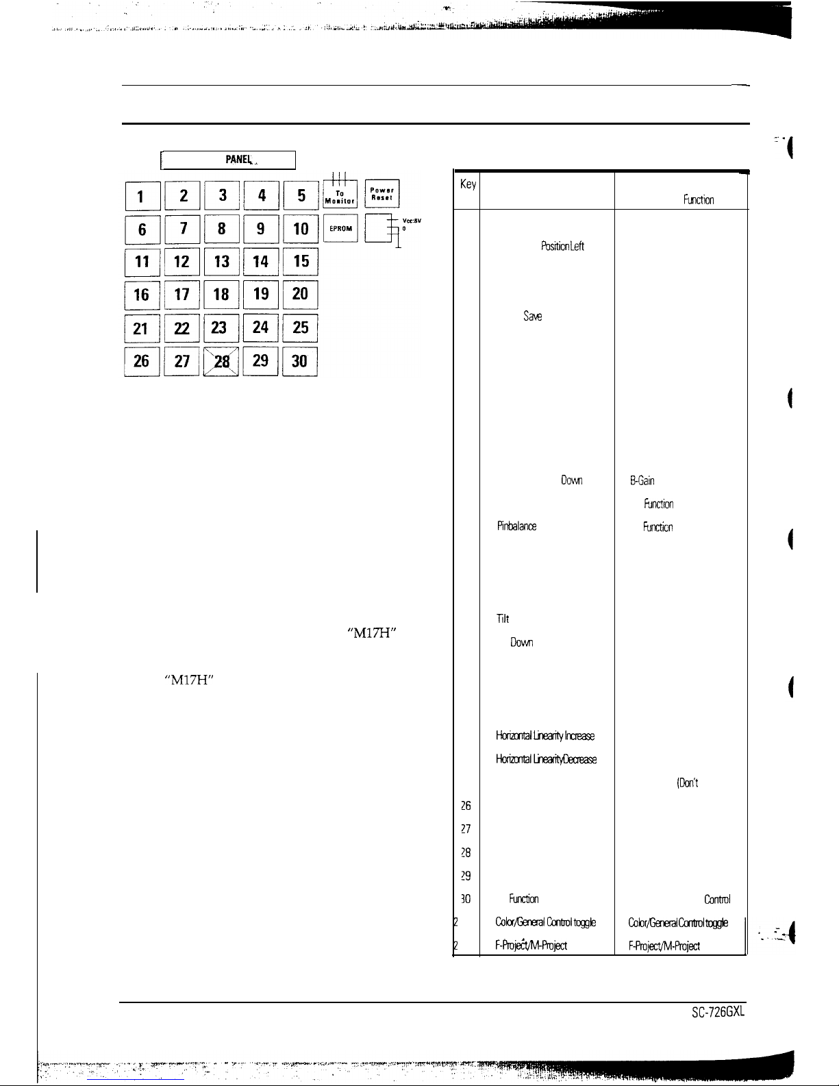
6-3 Using the Microcomputer Control Jig
I
LCD
PANEL _
Figure 6-I. Micom Control Jig Keypad
Notes:
Changes made without the micom jig are saved
only to the user mode settings. As such, these
setting are not permanently stored and may be
inadvertently deleted by the user.
Selecting the monitor series and type:
1.
Simultaneously press buttons 29 and 24 to
select “M-Project” as the monitor series.
2.
Press button 25 to select the monitor type.
Hold down button 25 until you see
“M17H”
plus the OEM name for the monitor under test.
For example, hold down button 25 until you
see
“M17H”
if you are working on a “Dell 17.”
Table 6-l. Micom Control Jig Function Keys
W
General Control
Color Control
No.
Key Function
Key
Fllnction
1
Horizontal Position Right
R-Gain Increase
2
Horizontal
P&ion Left
R-Gain Decrease
3
Parallelogram Right
ACL Increase
4
Parallelogram Left
ACL Decrease
5
Mode
SUE
Color Save
6
Horizontal Size Increase
G-Gain Increase
7
Horizontal Size Decrease
G-Gain Decrease
8
Vertical Linearii Increase
Color CH-1 Standard Save
9
Vertical Linearii Decrease
Color CH-2 Standard Save
10
Standard Save
ACL Save
11
Vertical Position Up
B-Gain Increase
12
Vertical Position DOW
EGain
Decrease
13
Pinbalance Left
No
Function
(Don’t Use)
14
Pinbalance
Right
No
Functicn
(Don’t Use)
15
All Mode Save
No Function (Don’t Use)
16
Vertical Size Increase
R-Bias Increase
17
Vertical Size Decrease
R-Bias Decrease
18
Tilt
up
No Function (Don’t Use)
19
lilt
DOW
No Function (Don’t Use)
20
User Mode Delete
No Function (Don’t Use)
21
Barrel
G-Bias Increase
22
Pincushion
G-Bias Decrease
23
Hc<allinearih/lnaease
No Function (Don’t Use)
24
HokltiILineacmpeaease
No Function (Don’t Use)
25
Model Selection
No Function
(Don’t
Use)
xi
Trapezoid Up
&Bias Increase
!7
Trapezoid Down
B-Bias Decrease
!8
No Function (Don’t Use)
No Function (Don’t Use)
!9
Shift
Shift
IO
No
Fution
(Don’t Use)
Manual/Auto Color
Control
t23
Color/General~ltoggle
Cobr/Genecal Gxtml @$e
t24
F-Pmje&M-Project
toggle
F-Project/M-Pmject
toggle
6-2
SC-726GXL
-. .
-4
6-3-l General Control
6-3-2 Color Control
Use general control to test and adjust the shape
and size of the display.
Use
color control to test and adjust the color
coordinates the monitor displays.
1.
Simultaneously press buttons 28 and 23 to
toggle between General Control and Color
Control. Select “General Control.”
1.
Simultaneously press buttons 28 and 23 to
toggle between General Control and Color
Control. Select “Color Control.”
2.
Standard Save: Press button 10 to do a
memory data dump and load the standard
picture data from the EPROM on the micom
control jig.
2.
Press button 8 (for 9300K setting) or 9 (for
6500K settings) to do a memory data dump
and to load the standard picture color data
from the micom control jig.
Note: This step is necessary only if the EPROM
Note: This step is necessary only if the EPROM
on the control jig has more recent data than the
on the control jig has more recent data than the
EPROM on the monitor PCB. Check for a
EPROM on the monitor PCB. Check for a
Service Bulletin or Service Manual
Service Bulletin or Service Manual
Supplement.
Supplement.
3.
Optimize the standard timing mode (60
kHz /75
Hz) using the micom control jig as described on
pages 6-3 through 6-5 of this manual.
3.
Optimize the standard timing mode using the
micom control jig as described on pages 6-6
and 6-7 of this manual.
4.
After completing all standard timing mode
adjustments, press button 15 to save the data
for all modes. The monitor’s microprocessor
adjusts the other modes according to a
predefined formula.
4.
5.
6.
Press button 5 to save the picture color data.
Press button 10 to save ACL data.
5.
Using a signal generator, scan the other timing
modes and make adjustments as needed. Each
time you make a change, press button number
5 to save the data.
When you are through, disconnect the micom
control jig and proceed with other tests and
adjustments.
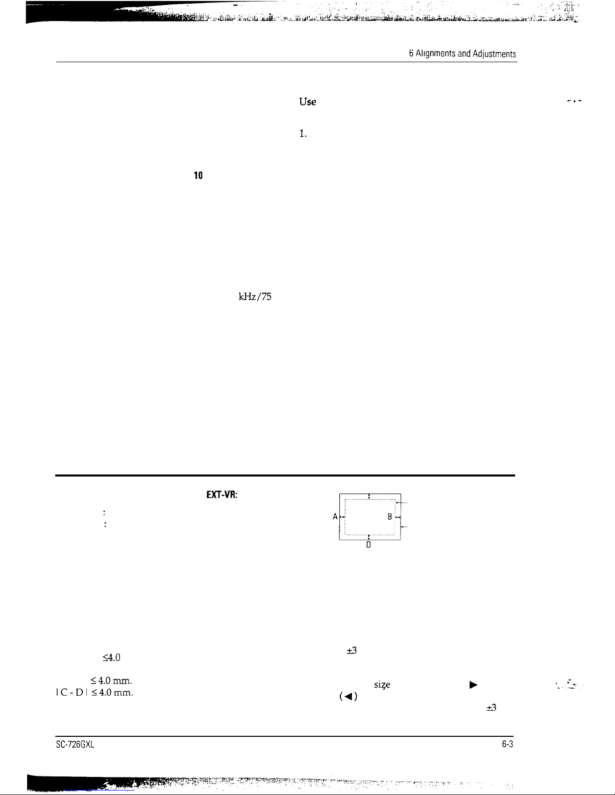
6-4 Display Control Adjustments
Unless otherwise specified, adjust the
EXT-VR:
Contrast
:
Max. (Fully clockwise)
Brightness : Max. (Fully clockwise)
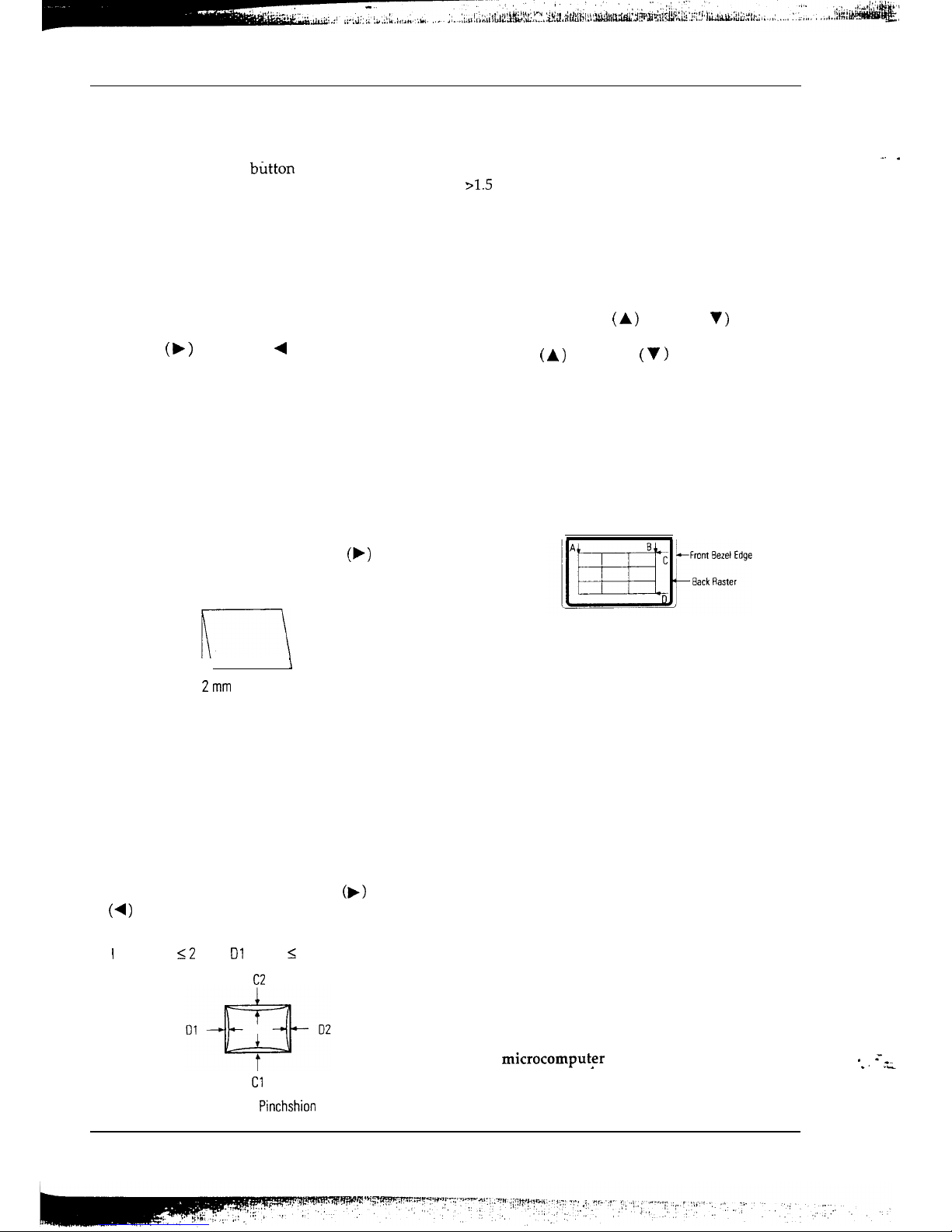
6-4-l Centering
Centering means to position the center point of the
display in the middle of the display area.
Horizontal size and position and vertical size and
position control the centering of the display.
Adjust the horizontal size and vertical size to their
optimal settings: 306 mm (H) x 230 mm (V)
Adjust the horizontal position and vertical
position to
3.0
mm of the center point of the
screen.
IA-BI <4.Omm.
IC-DI
<4.Omm.
C
-Display area
-Edge
of bezel
0
Figure 6-2. Centering
6-4-2 Horizontal Size Adjustment
With microcomputer control jig:
Press the horizontal size up button (6) or
horizontal size down button (7) to adjust the
horizontal size of the display pattern to 306 mm.
(Tolerance: 10 mm.)
Without microcomputer control jig:
After pushing the
siqe
button, push the ( b )
button or ( 4 ) button to adjust the horizontal size
of the display pattern to 306 mm. (Tolerance
&3
mm.)
-. -
6 Alignments and Adjustments
6-4-3 Vertical Size Adjustment
With microcomputer control jig:
Press the vertical size increase button (16) or the
vertical size decrease button (17) to adjust the verb
ical
image or pattern to 230 mm. (Tolerance:
k3mm.)
Without microcomputer control jig:
After pushing the size button, push the ( A )
button or ( V ) button to adjust the vertical size of
the display pattern to 230 mm.
(Tolerance: r3 mm.)
6-4-4 Horizontal Position Adjustment
With microcomputer control jig:
Press the horizontal position right button (1) or the
horizontal position left button (2) to center the
image or test pattern on the raster.
Without microcomputer control jig:
After pushing the position button, push the ( b
)
button (move right) or ( 4 ) button (move left) to
center the image or test pattern on the raster.
6-4-5 Vertical Position Adjustment
With microcomputer control jig:
Press the vertical position up button (11) or
vertical position down button (12) to center the
vertical image or pattern on the raster.
Without microcomputer control jig:
After pushing the position button, push the ( A
)
button (move up) or (V ) button (move down) to
center the image or the test pattern on the raster.
6-4-6 Vertical Linearity Adjustment
Linearity affects the symmetry of images
on the screen. Unless each row or column of
blocks in a crosshatch pattern is of equal size, or
within the tolerances shown in Tables 6-2 and 6-3,
an image appears distorted, elongated or
squashed.
To adjust the Vertical and Horizontal Linearity,
refer to Tables 6-2 and 6-3 for the tolerance range.
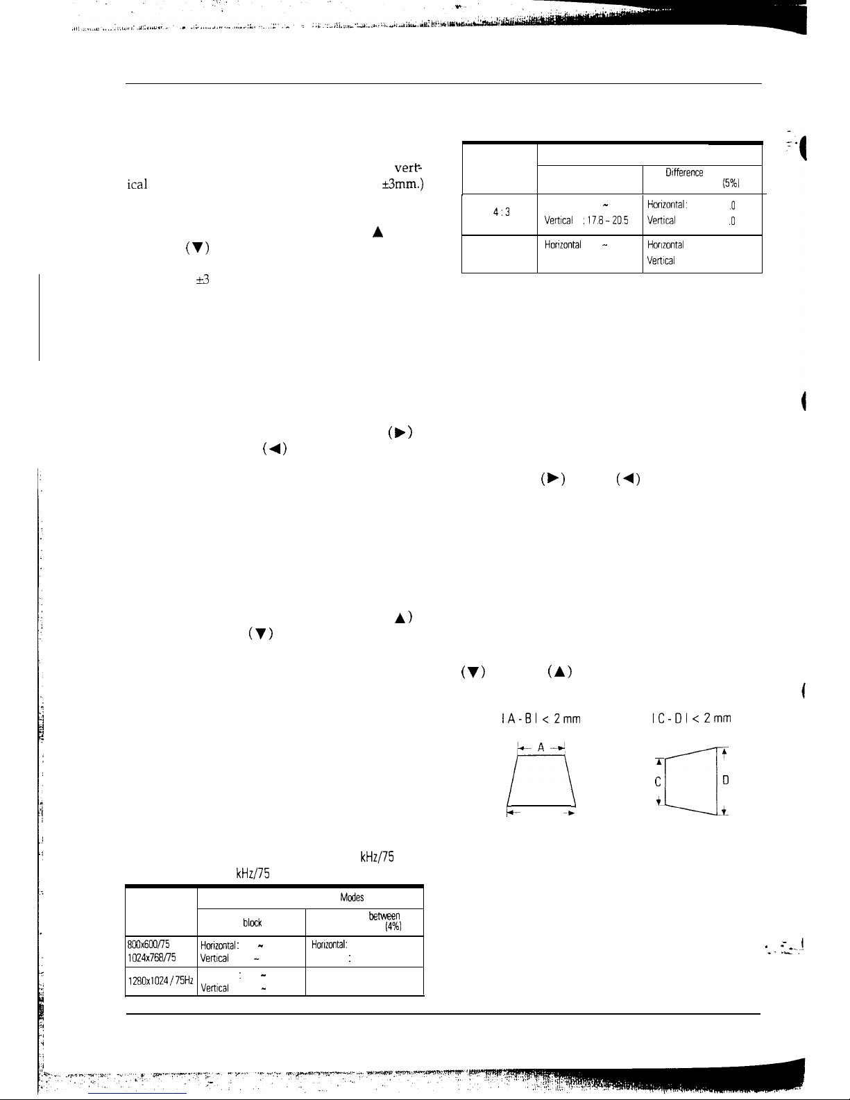
Table 6-2. Standard Mode Linearity: 60.023
kHz/75
Hz,
79.976 kHz/75 Hz
Factory Preset Timing
Modes
Standard Mode Each
block
(5%)
Difference
between
adjacent blocks
(4%)
8GUx6W75 Hz
Hortzontal
:
18.2 - 20.1
Horizontal:
Less than 0.8
mm
1024x768/75
HZ
Vertical
18.2 - 20.1
Vertical: Less than 0.8
mm
12EOx1024 / 75Hz
Horizontal : 17.1 - 18.9
Horizontal: Less than 0.7 mm
Vertical
: 18.2 - 20.1
Vertical
Less than 0.8
mm
Table 6-3. Other Modes Linearity: VGA, 8514/A,
XGA, MAC, etc.
Supported Timing Modes
Screen Ratio
Each block (7%)
Olfference
between
adjacent blocks
(5%1
4:3
5.4
Horizontal
17.8 - 20.5
Horizontal:
less
than1 .O
mm
Verwal
.178-205
Vertical
:
less
than1 .O
mm
Horuontal
16 7 - 19.2
Horizontal
less
than
0.9 mm
Vertical
,178-Z
Verwai
less than 1 0 mm
With microcomputer control jig:
Press the vertical linearity increase button (8) or
vertical linearity decrease button (9) to optimize
the image or the test pattern.
Without microcomputer control jig:
To activate the vertical linearity adjustment
function, push and hold in both the position and
the size buttons for longer than three seconds, or
until the power indicator LED changes from
orange to green and back to orange.
Use the right ( b ) and left (4 ) buttons to correct
the vertical linearity.
6-4-7 Horizontal Linearity Adjustment
With microcomputer control jig:
Press the horizontal linearity increase button (23)
or horizontal linearity decrease button (24) to
optimize the image or the test pattern.
Without microcomputer control jig:
After pushing G/D button once, push the
( v )
button or ( A ) button to make the image or
the test pattern rectangular.
IA-61 <
Zmm
IC-III <
Zmm
L A -4
r-7
I
\
it
B
m*
A
T
C
r---l
0
i
L--.-L
Figure 6-3. Trapezoid
6-4
SC-726GXL
*
=__.!
*.
I_.
6 Alignments and Adjustments
6-4-8 Pinbalance Adjustment
With microcomputer control jig:
Press the pinbalance left button (13) or pinbalance
right button (14) to optimize the image or test
pattern.
Without microcomputer control jig:
To activate the pinbalance adjustment function,
push and hold in both the position and the size
buttons for longer than three seconds, or until the
power indicator LED changes from orange to
green and back to orange.
Use the up ( b ) and down ( 4 ) buttons to correct
the pinbalance distortion of one or both sides.
6-4-9 Parallelogram Adjustment
With microcomputer control jig:
Press the parallelogram right button (3) or the
parallelogram left button (4) to make the image or
test pattern rectangular.
Without microcomputer control jig:
After pushing G/D button twice, push
(F)
button
or (4 ) button to make the image or test pattern
rectangular.
k-----l
\
Zmm
Figure
6-4. Parallelogram
6-4-10 Side Pincushion Adjustment
With microcomputer control jig:
Press the barrel button (21) or the pincushion
button (22) to straighten the sides of the test
pattern or image.
Without microcomputer control jig:
After pushing G/D button once, push
(b)
button
or
(4)
button to straighten the sides of the test
pattern or the image.
I
Cl I, I C2 I I2 mm, I Dl I, I D2 I
I
C2
2
mm.
Cl
Figure 6-5.
Pinchshion
6-4-11 lilt Adjustment
Direction: Monitor MUST face to the East.
Use mechanical adjustment if correction needed is
p1.5
mm.
With microcomputer control jig:
Press the tilt up button (18) or the tilt down button
(19) to correct the tilt of the display.
Without microcomputer control jig:
Push the G/D button twice to display the tilt OSD.
Push either the tilt up ( A ) or down ( V ) button to
display the tilt OSD.
Use the up ( A) and down
(
V
)
buttons again to
correct the tilt of the display.
CRT Tilt Adjustment
Mechanical Adjustment:
Reassemble the CRT with fastening screws so that
the dimensions A, B and C, D are separately equal.
If you are unable to correct the tilt, contact the
regional service center for CRT replacement.
Figure 6-6. CRT Tilt Adjustment
Degauss
No adjustments available for degaussing circuit.
The degaussing circuit can effectively function
only once per minute. If available, use an external
degaussing coil during servicing.
Warning: Don’t hold the degauss button down for
longer than 3 seconds. If you do, it resets all data
in the user memory area. If this occurs, you must
remake the user adjustments.
6-4-12 To Delete the User Mode Data
With microcomputer control jig:
To delete the picture data from user’s modes, push
user’s mode delete button (20).
Without microcomputer control jig:
To delete the picture data from user’s modes, press
the degaussing button for 5 or more seconds.
6-4-13 Save the Data
With microcomput$r control jig:
To save the picture data for a mode, push the
mode save button (5).
SC-726GXL
6-5
_. .
* =__
*. ._
6 Alignments and Adjustments
6-5 Color Adjustments
Note:To make color adjustmentsyoumusthave
one of the following configurations:
.
1.
Micom Control Jig and Signal Generator.
or
2. Micom Control Jig and Computer with
Samsung DM 200 software or
DisplayMate
for
Windows software from
Sonera
Technologies.
Before making adjustments check that the video
signals are as follows:
Video : Analog 0.714 Vp-p (at 75 R terminated).
Sync
:
Synchronizing: Separate
TTL
level.
Unless otherwise specified, use 1024x768
signal (60
kHz/75
Hz) for the
adjustments.
6-5-l Color Coordinates (Temperature)
Color temperature is a measure of the radiant
energy transmitted by a color. For computer
monitors, the color temperature refers to the
radiant energy transmitted by white. Color
coordinates are the X and Y coordinates on the
chromaticity diagram of wavelengths for the
visible spectrum.
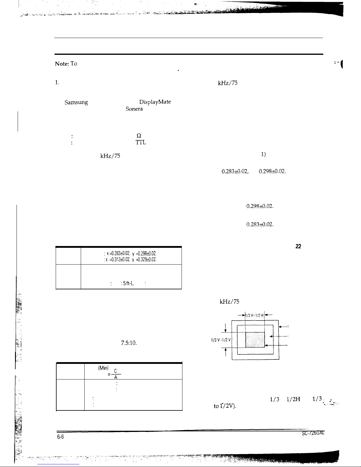
Table 6-4. Color Coordinates
Value
9300" K :
x=0.283+0.02,
y
=0.298~.02.
6500" K
: x
=0.313*0.02.
y
=0.3291tO.O2.
Conditions
Display Image: White flat field at the
center of display area.
Luminance
:
Min
: 5
ft-L, Max : 24 ft-L.
6-5-2 Luminance Uniformity
Luminance uniformity means that the luminance
at the position of the lowest brightness must be
more than 75% of the luminance at the area with
the highest brightness. Luminance is considered
uniform only if the ratio of lowest to highest
brightness is not less than
7.5:10.
Table 6-5. Computing Luminance Uniformity
,
Value
75 % (Min)
Variation = + x 100
Conditions
Display Image : White flat field.
Luminance
:
Brightness cut off, Contrast Max.
A : Luminance at position of highest brightness.
C : Luminance at position of lowest brightness.
6-5-3 Color Adjustments for 9300°K
-.
.
- 1
6-5-3 (a) Adjustment of the Back Raster Color
(60
kHz/75
Hz, Back raster pattern)
1. Turn the contrast and the brightness
controls fully clockwise (maximum
condition).
2. Adjust the screen VR of the FBT so that the
brightness of back raster is 0.5 to 0.7 ft-L
(typically 0.6 ft-L).
3. Press button 8 to download the standard
color data (channel 1) from the micom jig.
4.
5.
6.
For 9300” K color adjustment:
x =
0.283d.02,
y =
0.298rO.02.
For 6500” K color adjustments see section
6-5-4 “Color Adjustments for 6500” K.”
Use buttons 26 and 27 to set the “y”
coordinate to
0.298Fo.02.
Use buttons 16 and 17 to set the “x”
coordinate to
0.283+3.02.
Note: If the above adjustments cannot be
done to each coordinate, press button 21 to
increase the green bias, or button 22 to
decrease the green bias and repeat
procedures 4 and 5.
After completing the adjustments, press
button 5 to save the data.
6-5-3 (b) Video Gain Adjustment
(60
kHz/75
Hz, Green box pattern)
Front Bezel
Opening
Back Raster
Green Window
Figure
6-7.
Green Box
Pattern
1. Display the green window pattern using a
range for which the ACL Circuit is not
active (within ranges
l/3
to
1/2H
and
l/3 ;
.___._
to
Q2V).
*. I_.
6 Alignments and Adjustments
2.
3.
Turn the contrast and the brightness
controls fully clockwise.
Press buttons 6 and 7 (G-Gain control) to
adjust the brightness of the green gain to
37-+1 ft-L.
Note: If you can’t increase the green gain to
the appropriate value, press button 3 to
increase the ACL point.
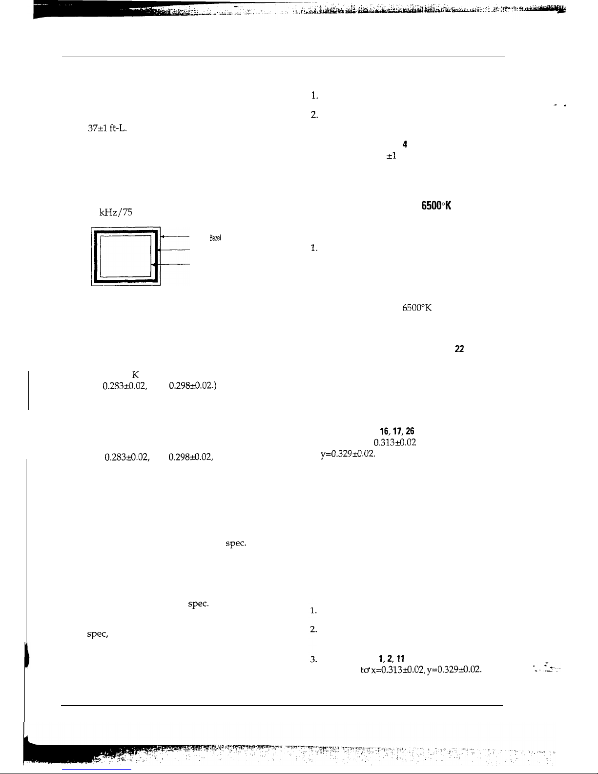
6-5-3 (c) White Balance Adjustment
(60
kHz/75
Hz, Full white Pattern)
II
Front
Sezel
Opening
Back Raster
White Window
Figure
6-8. Full White Pattern
1. Turn the contrast and the brightness
controls fully clockwise.
2. Use the R-Gain buttons 1 and 2 and B-Gain
buttons
11
and
12 to
make the video white.
(For 9300” K color adjustment:
x = 0.283&.02,
y = 0.298&.02.)
Note: Do not touch buttons 6 and 7.
3. Press button 5 to save the data.
6-5-3 (d) White Balance Fine Adjustment
(x =
0.283&.02,
y = 0.298&.02,
Full White pattern)
Note: Do not touch buttons 6 and 7 (G-Gain).
1.
2.
3.
4.
5.
Adjust the contrast control so that the
brightness of the video is about 5 ft-L.
Check whether the white coordinates of the
video meets the above coordinate
spec.
Adjust the contrast control so that the
brightness of the video is about 20 ft-L.
Check whether the white coordinates of the
video satisfies the above
spec.
If the white balance differs from the above
spec, readjust it to within specifications.
When correct, press buttons 5 to save.
6-5-3 (e) ACL point Adjustment
1,
.
2,
3.
4.
Display the full white pattern.
Turn the contrast and the brightness
controls fully clockwise.
Press buttons 3 and $ (ACL) so that the
brightness is 30 +l ft-L.
Press button
10
to save the ACL setting
value.
6-5-4
Color Adjustments for
6500°K
6-5-4 (a) Back Raster Color Adjustment
1.
Display the back raster pattern.
2. Turn the contrast and the brightness
controls fully clockwise.
3. Press button 9 to load the standard color
data (channel 2) for 6500’K from micom
control jig.
4. Adjust the brightness of the back raster to
0.5 to 1.0 ft-L using buttons 21 or 22 (G-Bias
control). If you don’t need to adjust the
brightness, skip this step.
Note: For 6500” K adjustments you must not
control the screen VR of the FBT. If you do
so, the 9300°K setting values are changed.
5. Using buttons
16,17,26
and 27, adjust the
R-Bias to x =
0.313&.02
and B-Bias to
y=O.329-+0.02.
6. Press button 5 to save the bias data for
6500°K.
6-5-4 (b) Video Gain Adjustment
1. This procedure is the same as that of
9300°K.
2. Refer to the procedure for 9300°K on
page 6-6.
6-5-4 (c) White Balance Adjustment
^. .
Display a full white pattern.
Turn the contrast and the brightness
controls fully clockwise.
Using buttons
1,2,11
and 12 set the R/B
gain data td x=0.313&.02,
y=O.329&.02.
SC-726GXL
6-7

6 Alignmenmts and Adjustments
6-5-4 (d) White Balance Fine Adjustment
6-5-4 (e) ACL Point Adjustment
Refer to the procedure for 9300°K on page 6-7.
Refer to the procedure for 9300°K on page
6-7.
-
-.
.-
t
6-6 Focus Adjustment
.
1.
Display the H character pattern so that the
3.
Adjust the focus control of the FBT to display
focus adjustment can be done. (Apply
the sharpest image possible.
1280x1024/60
Hz mode to the monitor.)
4.
Use locktite to seal the focus control in
2.
Turn the contrast and the brightness controls
position.
fully clockwise.
6-7 Color Purity Adjustment
Color purity is the absence of undesired color.
Conspicuous mislanding (unexpected color in a
uniform field) within the display area shall not be
visible at a distance of 50 cm from CRT surface.
Conditions
Direction
:
Monitor facing east.
Display image: White flat field.
Luminance
:
Cutoff point at the center of
display area.
Note: Color purity adjustments should only be a
attempted by qualified personnel.
For trained and experienced service technicians
only.
Use the following procedure to correct minor color
purity problems:
Make sure the display is not affected by
external magnetic fields. Use an external
degaussing coil to neutralize magnetic
fields which may be affecting color purity.
Very carefully break the glue seal between the
two-pole purity convergence magnets (PCM),
band and the spacer (see Figure
6-10).
Caution: The convergence bow magnets are
not user or service technician adjustable. Do
not allow these magnets to move.
Make sure the spacing between the PCM
assembly and the CRT stem is 29
mm&l
mm.
Display a red pattern over the entire display
area.
Adjust the purity magnet rings on the PCM
assembly to display a pure red pattern.
(Optimum setting:
X=0.625&0.015,
Y=0.340?O.015)
Adjust each comer and the center to meet the
red color tolerances listed below.
Repeat steps 4 through 6 using a green pattern
and again, using a blue pattern.
Table 6-6. Color Purity Tolerances
X=O.63a.O2 Y=O.34&.02
x=0.2&0.02 Y=O.61&.02
X=0.15+0.02
Y=O.O7+0.02
(For 9300°K color adjustment: X=0.283&.02,
Y=O.298~tO.O2)
8.
When you have the PCMs properly adjusted,
carefully glue them together to prevent their
movement during shipping.
.
=_.I
*.
I-._..
6-8
SC-726GXt.
6 Alignmenmts and Adjustments
6-8 Convergence Adjustments
Misconvergence occurs when one or more of the
electron beams in a multi beam CRT fail to meet
the other beams at a specified-point.
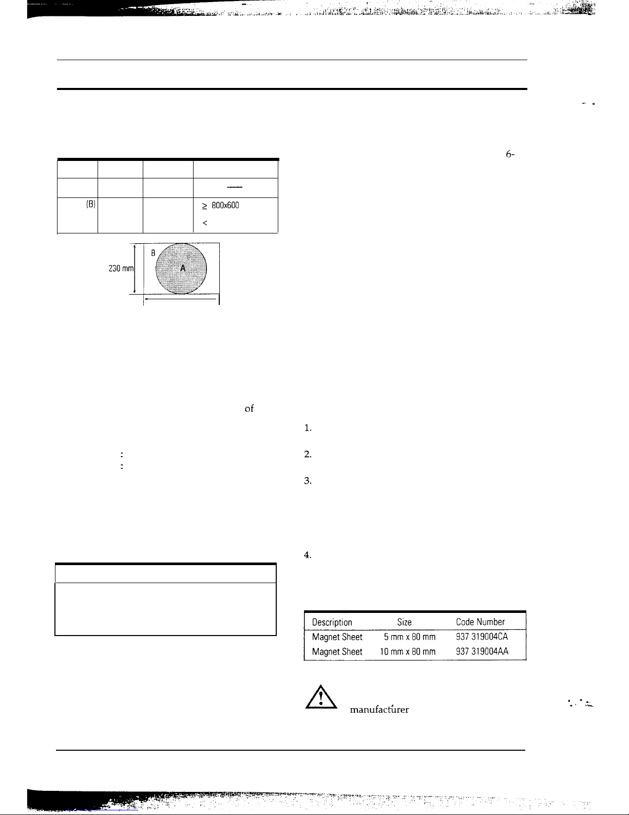
Table 6-7. Misconvergence Tolerances
Position
Error in mm CRT Dot Pitch
Remark
Center
(A)
0.30 0.26
-
Edge
(B)
0.30 0.26
2
800x600
resolution
0.40 0.26
<
800x600 resolution
306
mm
I
Figure 6-9 Convergence Measurement Areas
6-8-l Static (Center) Convergence
Static convergence involves the alignment of the
red, blue and green lines in the center area of the
display.
See Dynamic Convergence” for alignment of the
color fields around the edges of the display.
Conditions
Direction
:
Monitor facing east
Warm-up: 30 minutes
Display image: Crosshatch pattern
Tolerances : See Table 6-7
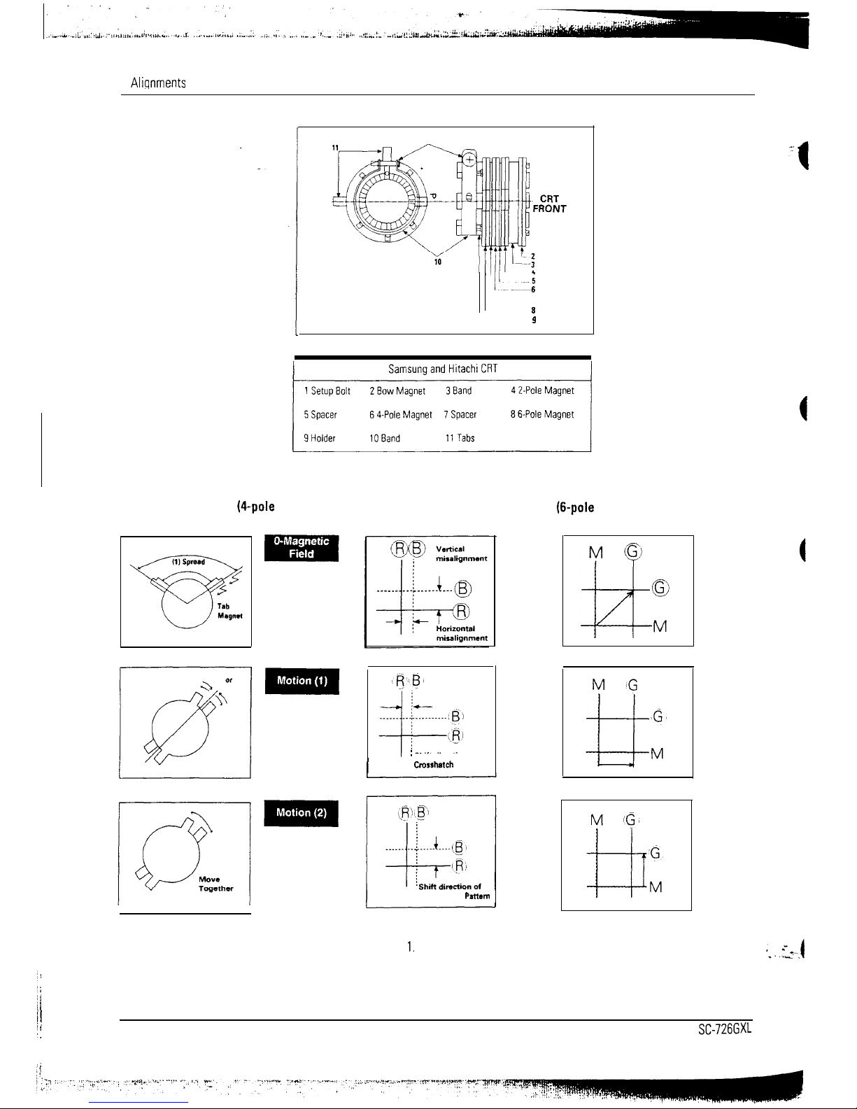
As shown in Figures 6-10, CRTs used in these
monitors all have the same magnet configuration
as shown in Table 6-8 below.
Table 6-8. Magnet Configurations
Magnet Order from Front of CRT
Convergence bow, two-pole,
four-pole, six-pole
Use the following steps to correct any static
misconvergence:
1.
Locate the pair of four-pole magnet rings.
2.
Unlock the rings and rotate the individual
rings (change the spacing between tabs) to
converge the vertical red and blue lines.
3.
4.
5.
6.
7.
Rotate the pair of rings (maintaining the
spacing between tabs) to converge the
horizontal red and blue lines.
After completing the red and blue center
convergence adjustment, locate the pair of
6-
pole magnet rings.
Rotate the individual rings (change the
spacing between tabs) to converge the vertical
red and blue (magenta) and green lines.
Rotate the pair of rings (maintaining the
spacing between tabs) to converge the
horizontal red and blue (magenta) and green
lines. Don’t rotate the 2-pole magnets, as they
adjust for color purity.
Mark the correct position for the magnets and
apply a small line of glue to hold the magnets
in place. Lock the rings in place.
6-8-Z Dynamic (Edge) Convergence
Use the following procedure to correct minor
dynamic (edge) misconvergence. If, after using
this procedure, dynamic, misconvergence is still
greater than the tolerance around the periphery of
the display area, contact the Regional Service
Center for possible CRT replacement.
Make sure the display is not affected by
external magnetic fields.
Make sure the static convergence is properly
adjusted.
Strategically place small magnetic strips
on the back of the CRT to correct the
misconvergence. Be careful not to remove the
paper protecting the adhesive on the magnetic
strip until you are satisfied with their
placement and the dynamic convergence.
When you are satisfied with the convergence
around the edge of the CRT, permanently glue
the magnets to the back of the CRT.
Table 6-9. Magnetic Strips
Warning Do not remove or change the position of
the factory installed wedges. These
wedges were installed by the CRT
manufac&er
and are properly placed
for this CRT. Removal may result in
damage to the CRT.
SC-726GXL
6-9
_. .
-
“s.
*. ._
6 Alignments and Adiustments
1
---
i!__IS
6
1
8
9
~
Figure 6-10. Magnet Configuration
Red and Blue Alignment
Red, Blue and Green Alignment
(Qpole
magnet movement)
(6-pole magnet movement)
:
Shii direction of
I
Crosshatch
Pattern
Crosshatch
Pattern
Figure 6-l
1.
Magnet Movements
i!
I!
‘.
6-10
SC-726GXL
6 Alignments and Adjustments
6-8-3 Bow Convergence Adjustments
Conditions
Direction: Monitor facing
East_
Display Image: Crosshatch pattern mixed with
RGB colors.
Bow convergence adjustments are not available for
any of the CRTs used in the SC-726GXL. While all
the CRTs have bow convergence magnets, they are
sealed in the CRT factory and are not user or
service technician adjustable. Do not touch these
magnets (see Figures 6-10). If color convergence
bow adjustment is out of alignment, replace the
CRT.
Bow misconvergence should not exceed the values
listed in Table 6-7: Misconvergence tolerances.
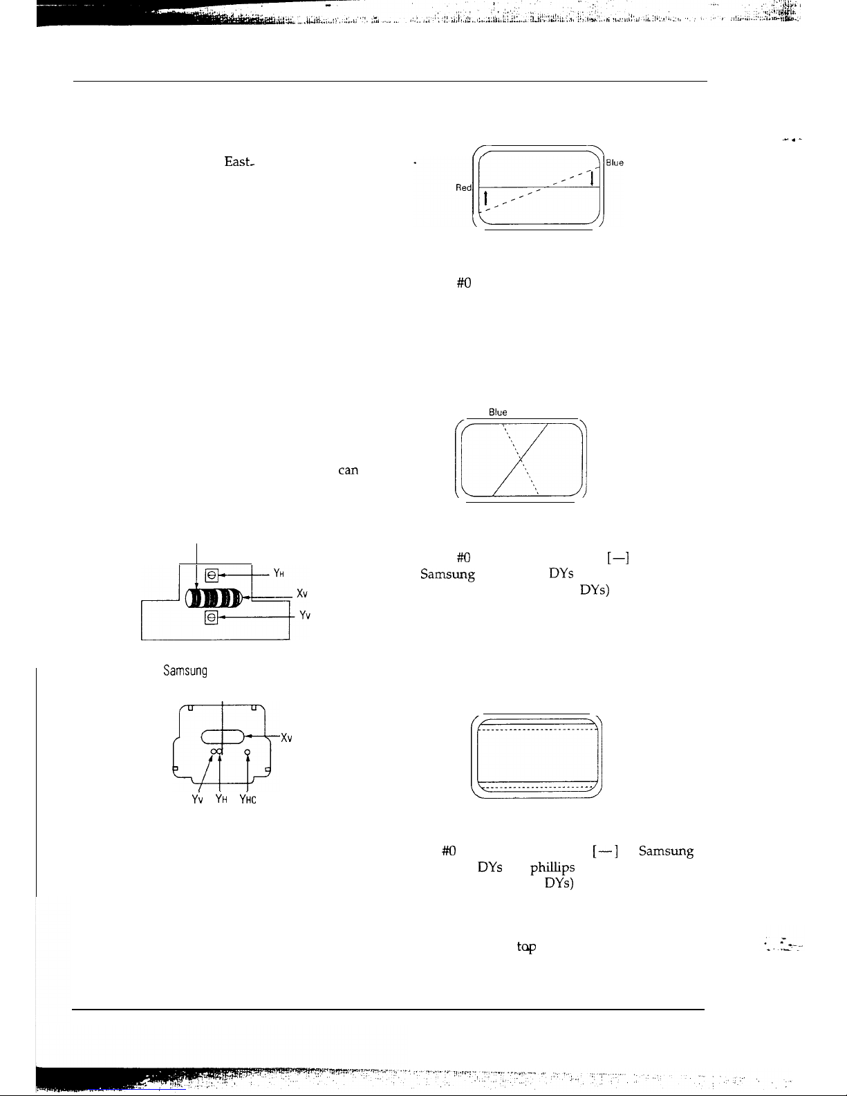
6-8-4 Balance Convergence Adjustments
Balance Convergence involves the alignment of
the red and blue lines when they are misaligned at
one end more so than at the other (X). The
deflection yoke holds the balance coils which
can
correct balance misconvergences.
Horizontal
Balance Coil
Figure 6-12.
Samsung
and Hitachi Deflection Yoke
a3
xv
Yi
YH
YilC
Figure 6-13. New Hitachi Deflection Yoke
6-8-4 (a) Horizontal Line Red and Blue Balance
Convergence
/I
a
Figure 6-14. Horizontal Line Balance Misconvergence
Use a
#/O
hexdriver at the Horizontal Balance
Coil (Xv). Turning the VR to the right raises the
right end of the blue line and lowers the left
end. Turning the VR to the left lowers the right
end of the blue line and raises the left end.
6-8-4 (b) Vertical Red and Blue Balance
Convergence
BlUl?
Red
Figure 6-15. Vertical Line Balance Misconvergence
Use a #O screwdriver (flat-head [-_I for
Samsung and Hitachi DYs and Phillips type [+]
for Matsushita [Panasonic]
DYs)
at the YH
variable register. Turning the VR to the left tilts
the blue line to the right. Turning it to the right
tilts the blue line to the left.
6-8-4 (c) Upper and Lower Horizontal Line
Convergence
Red
Blue
________________._.-.-.--
Red
Blue
rr
___.__________._._...--~
Figure 6-16. Upper and Lower Balance Misconvergence
Use a #O screwdriver (flat-head
[-_I
for Samsung
and Hitachi
DYs
and phillips type [+] for
Matsushita [Panasonic]
DYs)
at the Yv variable
register. Turning the VR to the left moves the blue
line at the top upward and at the bottom the line
moves downward. Turning it to the right moves
the blue line at the tq downward and at the
bottom the line moves upward.
SC-726GXL
6-l
1
_. . _

7 Troubleshooting
Notes:1,If picture does not appear, fully rotate the brightness and contrast controls clockwise before inspection.
.
2.
Check the following circuits:
*No
raster appears: Power circuit, horizontal output circuit, H/V control circuit and H/V output circuit.
*High voltage develops but no raster appears: Video output circuits.
*High voltage does not develop: Horizontal output circuits.
Horizontal line on raster
No
Check the power supply circuits.
(D618 and
R316)
Yes
Check the power supply circuits.
I::::_..:fi?-A~7rat::_“‘~~
_. . _
* --_.
*. ._ :
SC726GXL
7-l
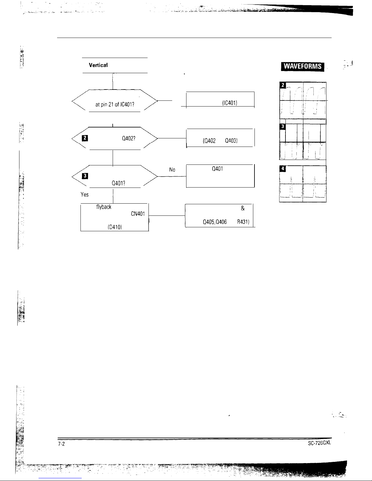
7 Troubleshooting
Verticai
line on raster
Does drive pulse appear
NO
Check the horizontal drive
circuits.
(IC401)
Yes
I
Does drive pulse appear
at emitter of
Q402?
No
Check the push-pull circuits.
(Q402
and
Q403)
Yes
Does drive output pulse
appear at drain
of
Q401?
Replace
Cl401
or check its
related circuits. (D407, 0408,
D409 and T401)
Yes
(
Check
flyback
pulse at collector
1
No
1
Check rhe H-size Drive &
of Q407 connection of
CN401
q
and its related circuits
0410)
output circuits
1
(D404,
Q405, Q406
and
R431)
 Loading...