

Samsung YP-P2 Service Manual
SERVICE
Manual
YEPP
Model Name : YP-P2
Model Code : YP-P2JCB/XEO
YP-P2JQW/XEO
YEPP
Refer to the service manual in the GSPN (see the rear cover) for the more information.
CONTENTS
1. Precaution
2. Product Specification
3. Disassembly & Reassembly
4. Troubleshooting
5. Exploded View & Part List
6. PCB Diagram
7. Schematic Diagram
YP-P2
This Service Manual is a property of Samsung Electronics
Co.,Ltd. Any unauthorized use of Manual can be punished
under applicable International and/or domestic law.
GSPN (Global Service Partner Network)
Area Web Site
North America service.samsungportal.com
Latin America latin.samsungportal.com
CIS cis.samsungportal.com
Europe europe.samsungportal.com
China china.samsungportal.com
Asia asia.samsungportal.com
Mideast & Africa mea.samsungportal.com
© Samsung Electronics Co.,Ltd. Oct. 2007
Printed in Korea

Contents
1. Precaution
1-1 Safety Precautions ............................................................................................1-1
1-2 Static Electricity Precautions .............................................................................
1-2
2. Product Specification
2-1 Product Feature ................................................................................................. 2-1
2-2 Specifications ....................................................................................................
2-2
2-3 Specifications Analysis ......................................................................................
2-3
2-4 Accessories .......................................................................................................
2-4
3. Disassembly & Reassembly
3-1 Overall Disassembly & Reassembly ..................................................................3-1
4. Troubleshooting
4-1 Checkpoints by Error Mode ...............................................................................4-1
4-2 Upgrade Methods ..............................................................................................
4-16
5. Exploded View & Part List
5-1 Exploded View ................................................................................................... 5-1
5-2 Electrical Part List ..............................................................................................
5-3
6. PCB Diagram
6-1 PCB Top ............................................................................................................6-1
6-2 PCB Bottom .......................................................................................................
6-3
7. Schematic Diagram
7-1 Overall Block Diagram ....................................................................................... 7-2
7-2 Power Management ..........................................................................................
7-3
7-3 TCC7801 Power_Block .....................................................................................
7-4
7-4 TCC7801 I/O Setting, Reset ..............................................................................
7-5
7-5 Memory (SDRAM, NAND-Flash) .......................................................................
7-6
7-6 Audio CODEC ...................................................................................................
7-7
7-7 24PIN I/O, Interface ...........................................................................................
7-8
7-8 WQVGA LCD Interface ......................................................................................
7-9
7-9 BLUETOOTH, FM .............................................................................................
7-10

Samsung Electronics 1-1
Precaution
1. Precaution
1-1 Safety Precautions
1. To remove dust from cabinet, use a dry cloth without using liquid and aerosol cleaner.
2. You should not use attachments not recommended by the company. Otherwise, it may cause critical damage.
3. You should not use this product near water such as bathtub, swimming pool or lake etc.
4. Power supply: A type of battery as displayed on the label should be only used.
5. You should not put any object or liquid into product. Otherwise, it may cause failure or mal-operation.
6. If replacement material is required, service engineer should use materials with the same standard.
The use of non-standardized materials may cause failure of product.

1-2 Samsung Electronics
Precaution
1-2 Static Electricity Precautions
Some semi-conductor parts may be easily damaged due to static electricity.
These elements are generally called as static electricity sense device (ESD). Typically examples of EST include
IC, some transistor and chip element for semi-conductor with electrical field effect.
The following methods should be used to reduce damage of elements occurred due to static electricity:
1. Contact and emit all the grounding objects with static electricity from your body before handling with elements
for semi-conductor or devices with elements for semi-conductor. You should purchase and use static electricity
arm rings or commercially available. You should remove it due to potential shock before supplying power to the
device under test.
2. You should place appliance on the conductive surface like aluminum film to prevent that static electricity is
accumulated or the device is disclosed outside after removing electrical appliance with the ESD device.
3. You should use only soldering iron that is ground when soldering the ESD device.
4. Minimize physical operation when handling with the ESD device for replacement without packing (Otherwise,
namely friction between cloth fibers or lifting of the foot from the carpet floor may cause static electricity enough
to damage the ESD device).

Samsung Electronics 2-1
Product Specification
2. Product Specification
2-1 Product Feature
Multimedia Player with a Stylish Slim Design
- Widescreen multi-format playback with great portability
- Ready for paid video downloads
- Allows easy communication using Bluetooth
Full Screen Touch - named EmoTrueTM UI(User Interface) that allows to operate sensually all
functions by using touch Icons on screen without uncomfortable buttons press.
High Resolution 3” WIDE QVGA(480x272) LCD that allows to play 16:9 Wide Video Contents.
WMV Format Supported (ready to Contents Service)
Built-in Bluetooth Function
A wireless networking technology that allows data transfer with Bluetooth-enabled stereo headsets, hands-free
devices (cell phones), and other external devices, all without cables.
2-2 Samsung Electronics
Product Specification
2-2 Specifications
Basic Specification
Model Name
YP-P2
JQB JAB JCB JQW JAW JCW JQR JAR JCR
Capacity
2GB 4GB 8GB 2GB 4GB 8GB 2GB 4GB 8GB
Color Black White Red Wine
Voltage
DC 5.0V / 500mA
Dimensions (WxDxH) / Weight
100 x 52 x 9.9 mm / 85g
Case Injection+PAD Print, SUS
Noise Ratio
85dB with 20KHz LPF (based on 1KHz 0dB)
Earphone Output
20mW (16Ω)
Output Frequency Range
20Hz ~ 20KHz
Temperature Characteristics
-5 ~ 35°C (23 ~ 95°C)
FM Frequency
87.5 ~ 108.0MHz
FM Signal-to-Noise Ratio
59dB
FM Distortion
0.8%
FM Effective Sensitivity
5dBu
Battery Type
Li-Polymer Rechargeable Battery
(Built-in Rechargeable Battery Capacity 830 mAh)
Playback Time
35 Hours of Music Playback (Based on MP3 128 kbps, Volume 20, Normal
Audio Mode), 5 Hours of Video Playback
Supported Files
Audio: MPEG1/2/2.5 Layer3 (8kbps~320kbps, 8kHz~48kHz),
WMA(5kbps~320kbps, 8kHz~48kHz), Ogg(Q-1~Q10)
Video: WMV9(Video: WMV9 Simple Profile, Audio: WMA9(Max 860kbps),
Resolution: 320X240 or 480X272, FrameRate: 30fps
Image: JPG(Baseline only)
LCD WQVGA 3” TFT LCD Touch Screen (480x272)
Color White, Black, Red Wine
Bluetooth
Operating
Frequency Range
TX/RX: 2402~2480 MHz
Supported
Specification
Version
2.0
Module BCM2048
Tx Output Power
Max 2.4 mW
Samsung Electronics 2-3
Product Specification
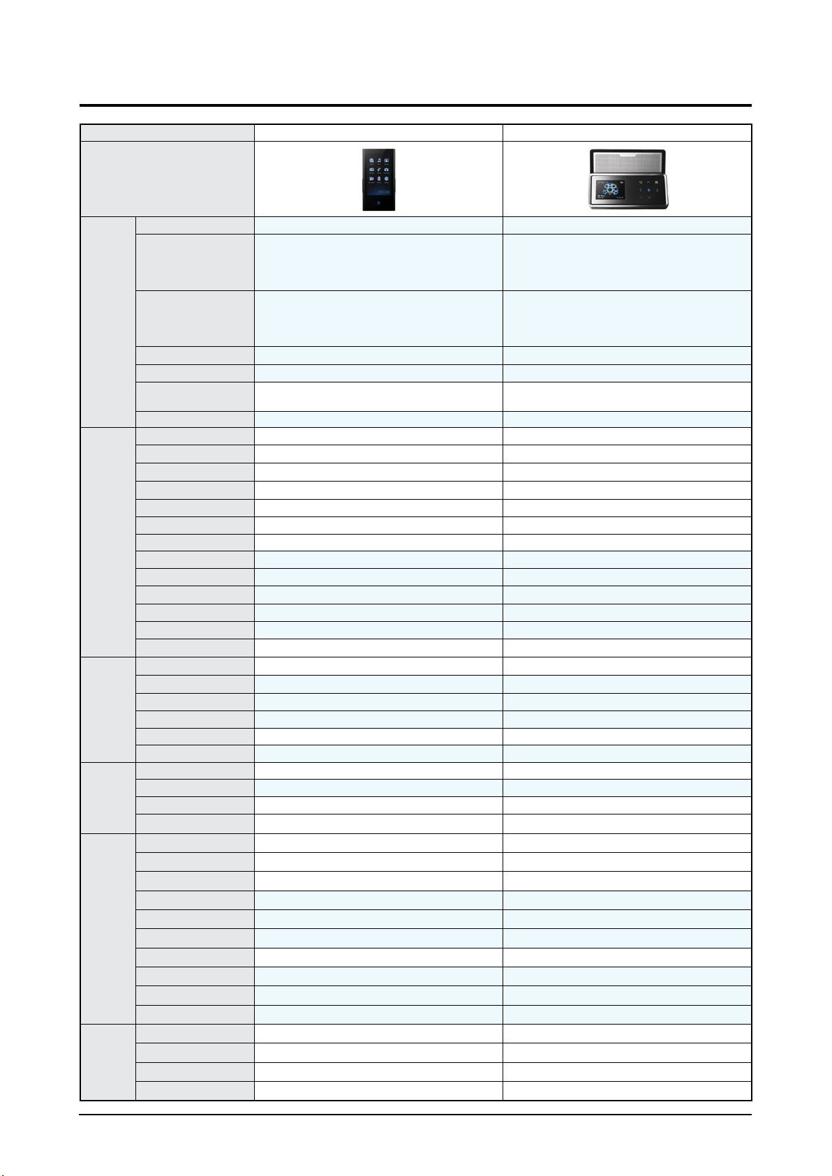
2-3 Specifications Analysis
Model Name
YP-P2 YP-K5
Photo
Basic
Storage TYPE
Flash memory (DSP) Flash memory (MLC)
LCD
SIZE: 3.0” 16.7M WQVGA
Display Color: 16.7M LCD
(Dot pitch: 0.0455(H) x 0.1365(V))
Resolution: 480RGB(H) x 272(V)
1.71” Full Color OLED
Playback Time
35 Hours of Music Playback with Earphones
(Based on MP3 128 kbps, Volume 20, Normal
Audio Mode), 5 Hours of Video Playback
30 Hours of Music Playback with Earphones
(Based on MP3 128 kbps, Volume 15, Normal
Audio Mode), 4 Hours Playback at Maximum
Speaker Volume
Capacity 2G / 4G / 8G
1G / 2G / 4G
Platform TCC78x (Telechips)
TCC77x (Telechips)
Battery Type
Li-Polymer Rechargeable Battery (Built-in Re-
chargeable Battery Capacity 830 mAh)
Li-Polymer Rechargeable Battery (Built-in Re-
chargeable Battery Capacity 830 mAh)
Color
White / Black / Red Wine Silver / Black
Files
MP3
WMA
OGG
(up to Q10) (up to Q10)
WAV
X X
AAC
X X
Audible
X X
JPEG
FLAC
X
APE
X
WMV WMV9
X
MPEG4 (SVI)
(480x272, 30Frame)
X
Swf (V4.0) - Game/UI Only
X
Others X
X
Sound
User EQ
(9 band control)
(9 band control)
Etc. Street Mode
-
Sound Feedback
(AUI)
-
Speed Control
(MP3 file play 0.75~1.3X)
-
Alarm
OUTPUT POWER
21mW/CH
25mW/CH
Tuner
FM
RDS
X
DMB
X X
Etc.
X X
Function
Playlist
Library
Photo Viewer
Text Viewer
(Book Mark/Page Up, Down)
X
Game
(Flash Gaming/3 games)
X
Wallpaper
(Wall paper change, Menu color change)
X
Clock
Etc. Clock Screen Saver, Dynamic EQ Display
-
Resume
(Audio/Video/Photo/Text)
(Audio/Photo)
Bookmark
(Video/Text only)
X
DRM
Netsync(korea)
SKT Melon(korea)
X X
WMA DRM
Janus
2-4 Samsung Electronics
Product Specification
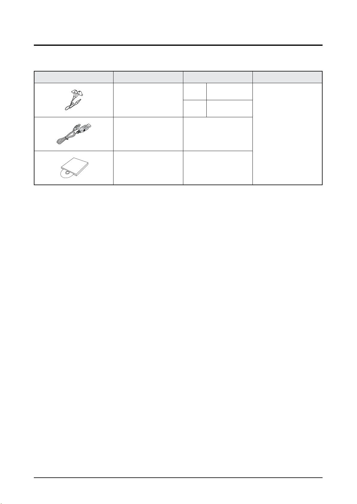
2-4 Accessories
2-4-1 Supplied Accessories
Accessories Item Item code Remark
Earphones
Black AH30-00087E
Samsung Service center
White AH30-00086H
USB Cable
AH39-00899A
Program Installation CD
AH46-00050A
Samsung Electronics 3-1
Disassembly & Reassembly
3. Disassembly & Reassembly
3-1 Overall Disassembly & Reassembly
- Be careful to follow the disassembly sequence described in the manual. Otherwise, the product
may be damaged.
- Be sure to carefully read and understand the safety instructions before performing any work as
the IC chips on the PCB are vulnerable to static electricity.
- Assemble in the reverse order of disassembly.
No. Part Name Description Description Photo
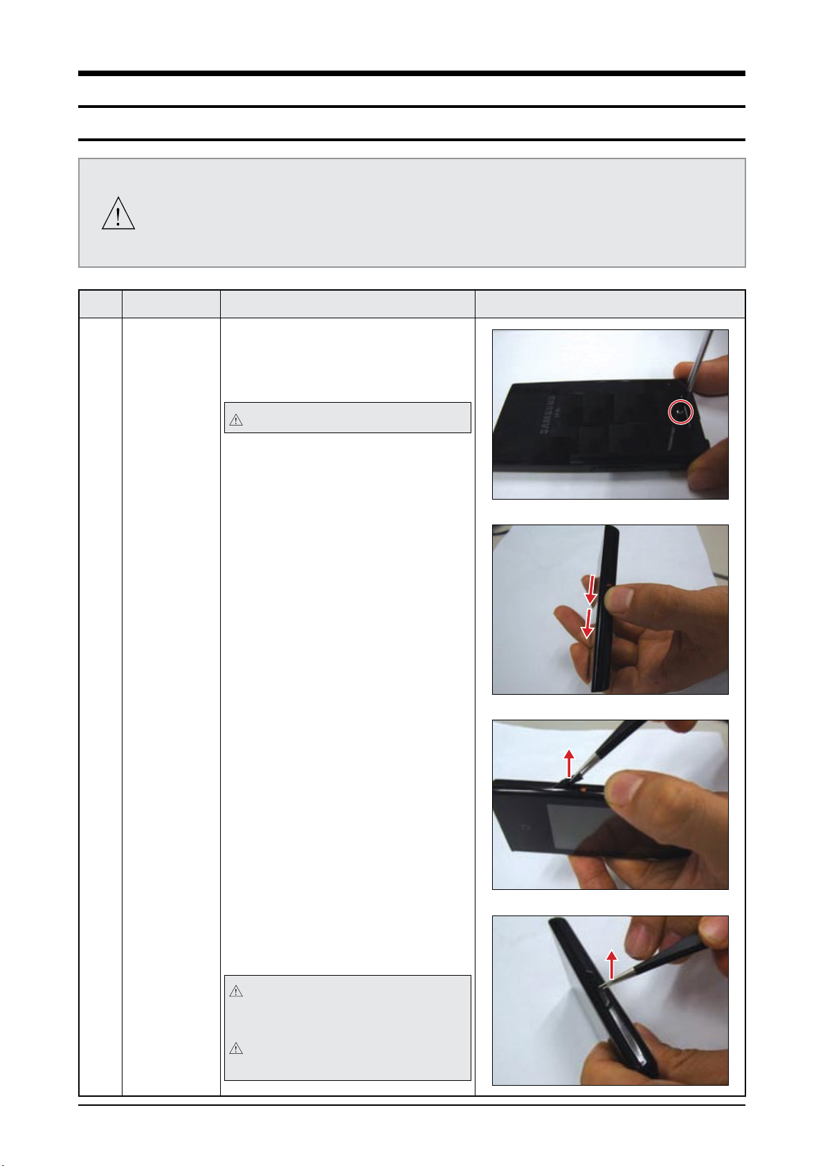
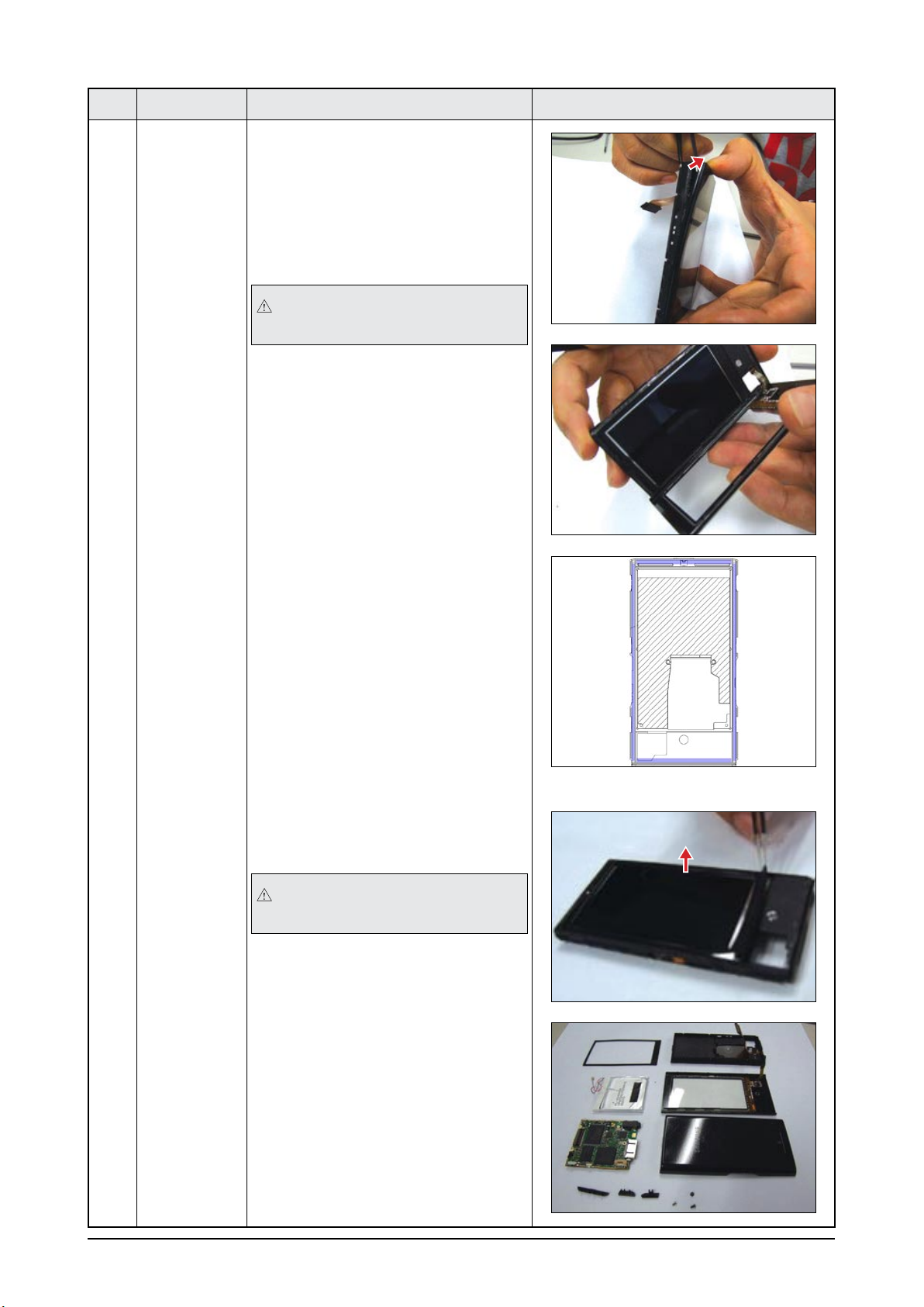
1 CABINET-
BACK
1) After removing the Serial Label at
bottom, remove the screw.
: M1.4,L2.5,HEAD2.5,MACHINE
The label must not be damaged.
2) Push up the HOLD switch.
3) Force a pair of tweezers between
HOLD KEY and POWER KEY then
remove POWER KEY.
4) Use the aperture to remove VOLUME
KEY at the opposite site.
Be sure not to damage CABINET-
BACK by using the aperture.
Use new KEYS when re-assemble in
case of damaging older KEYS.
3-2 Samsung Electronics
Disassembly & Reassembly
No. Part Name Description Description Photo
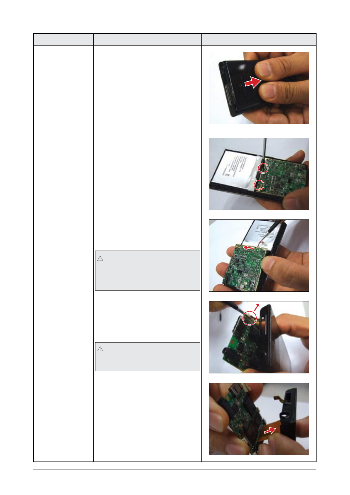
1 CABINET-
BACK
5) Push the CABINET-BACK in the
direction of the arrow to remove it.
Assemble all KEYS first and
assemble BACK-CABINET.
Insert one side of BACK CABINET
at HOLDER FRAME and push the
opposite side.
2 PCB 1) Remove the two (2) screws holding
the PCB in place.
: M1.7,L3,HEAD3.0,TAPTITE
2) Remove the BATTERY after lifting up
the PCB from the CABINET-FRONT
by using a pair of tweezers.
Be sure to observe BATTERY
polarity when re-connecting Battery.
If is connected opposite sides, the
SET will be hot and no power on.
3) Lift up PCB after pushing backward
from the USB CONNECTOR and
remove TOUCH-PAD PANNEL FPCB
from the ZIF CONNECTOR.
When removing the FPC-TOUCH,
be sure to use a pair of tweezers to
avoid a tear.
4) Unplug the LCD CONNECTOR and
then remove the PCB.
Samsung Electronics 3-3
Disassembly & Reassembly
No. Part Name Description Description Photo
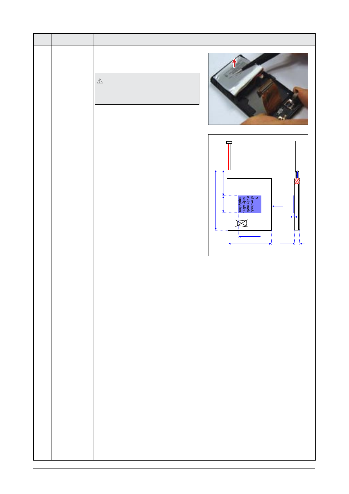
3 BATTERY-LI 1) Lift up the BATTERY by using a pair
of tweezers.
There will be possible to damage
BATTERY effect from double coated
tape.
Re-attach a new double coated tape
after removing an old thing, when
assembling a BATTERY.
Capadty:830mAh
Nominal Vottage:3.7V
CAUTION
Danger of exploslon if battery
is incorre ctly replaced.
Replace only with the
same or equiyalent type
ATL Made in china
44.3 max (including PCM)
20 20±3
25.0
44.0 max
41 max
A View
0.1
A
<Location of BATTERY double coated
tape.>
3-4 Samsung Electronics
Disassembly & Reassembly
No. Part Name Description Description Photo
4 CABINET-
FRONT
1) Use a pair of tweezers to remove
the CABINET-FRONT from the
HOLDER-FRAME.
(The CABINET-FRONT is attached
to the HOLDER-FRAME by a double
coated tape.)
Be careful not to make any scratches
as you remove it.
2) USE a pair of tweezers to remove
CUSHION-LCD.
Don’t remove the LCD which is glued
HOLDER-Frame by force.
3) A view of the device after
disassembly
<Location of ASSY HOLDER-FRAME double coated tape.>
Samsung Electronics 4-1
Troubleshooting
4. Troubleshooting
4-1 Checkpoints by Error Mode
Oscilloscope Setting Values
Voltage/DIV 2V/div
TIME/DIV 1m/div
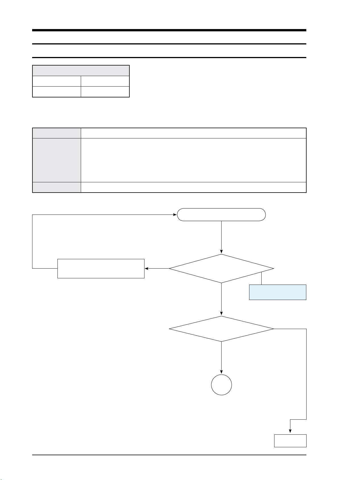
4-1-1 No Power
Symptom
Power does not turn on
Major Checklist
1
Check the power terminal connection (battery, adapter).
2
Check if the key signal is ‘HIGH’ when the POWER key is pressed.
(2.5V ~ 3.1V)
3
Check if the ENABLE pin signal of the DDCON IC is ‘HIGH’. (2.5V ~ 3.1V)
4
Check power.
(L300: 2.8V(MAIN), L301: 1.07V(CORE), L302: 1.8V(MEMORY), L303: 3.1V(LCD))
Caution
Be careful not to short anything out when checking the power line.
Refer to wave pattern
image of Table 4-1.
Does the power turn on after
recharging the battery?
Yes
No
Completion
The power does not turn on.
After insert battery to PCB,
Please TEST
No
1
Is battery inserted to Main PCB
normally?
A
Yes
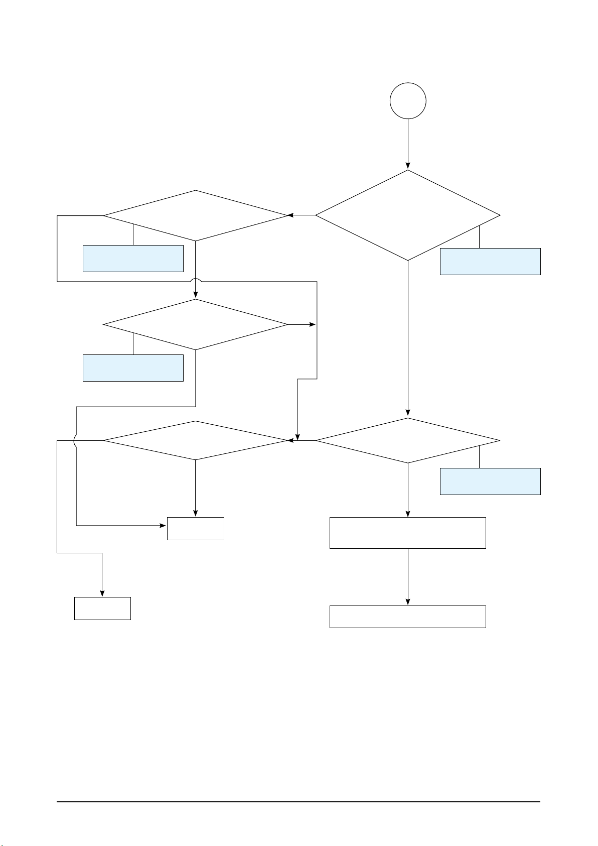
4-2 Samsung Electronics
Troubleshooting
Check power at the BATTERY
(single part).
Recheck after replacing the battery.
4
Check power.
L300: 2.8V(MAIN)
L301: 1.07V(CORE)
L302: 1.8V(MEMORY)
L303: 3.1V(LCD)
Yes
No
Check BATTERY power.
IC803(+), IC804(-)
Check MAIN 12Mhz clock
No
Defective
YesYes
No
No
No
A
Refer to wave pattern
image of Table 4-1.
Refer to wave pattern
image of Table 4-1.
Completion
3
Check DDCON enable
pin signal as ‘HIGH’
(2.5V~3.1V)
2
When power Key is on,
check key signal as ‘HIGH’?
(2.5V~3.1V)
Refer to wave pattern
image of Table 4-1.
Yes
Yes
Refer to wave pattern
image of Table 4-1.
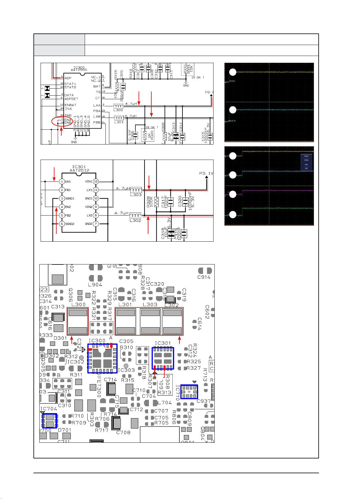
Samsung Electronics 4-3
Troubleshooting
Test Point IC300(1PIN, 19PIN), IC301(1PIN, 4PIN), L300, L301, L303, L302
Result Check for HIGH input
POWER Management Page, 7-3
POWER Management Page, 7-3
CON803
IC300
IC704
IC710
IC403
IC301
PCB Bottom Page, 6-3
<Table 4-1>
2
3
2
3
4 4
3
4
4
2
3
4
L300
4
L301
4
L303
4
L302
4 4
4-4 Samsung Electronics
Troubleshooting
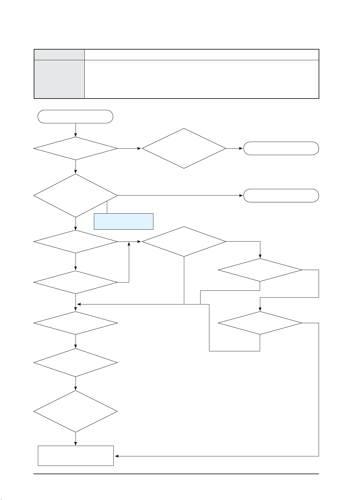
4-1-2 No Sound
Symptom No output at earphones
Major Checklist
Check if the earphones are normal. / Check the cold solder on the earphones jack.
1 Check if 3.1V is output from C714.
2 Check if 2.8V is output from C705.
3 Check if 1.8V is output from L704.
Does the YEPP
Logo Song play?
Are the earphones
normal?
Do R/L-CHs output
normally?
Are there skips and
noises?
Are the skips and
noises even when playing
another le?
Does the
same symptom persist
even after upgrading the
rmware to the latest
version?
Yes
No
Yes
Yes
Yes
Yes
Yes
Does the same
symptom persist even
after replacing the
earphones?
Does it play after
supplementing the solder
on the jack?
No
No
No
No
Yes
Yes
No
Power Defective
Check if IC703 is shorted.
Check if IC704 is shorted.
Replace the earphones
No
Yes
Yes
No
No Sound
Refer to wave pattern
image of Table 4-2.
1 / 2 / 3
Is audio codec voltage
a normally? C714: 3.1V,
C705: 2.8V, L704: 1.8V
Check
Replace the board
(needs thorough examination).
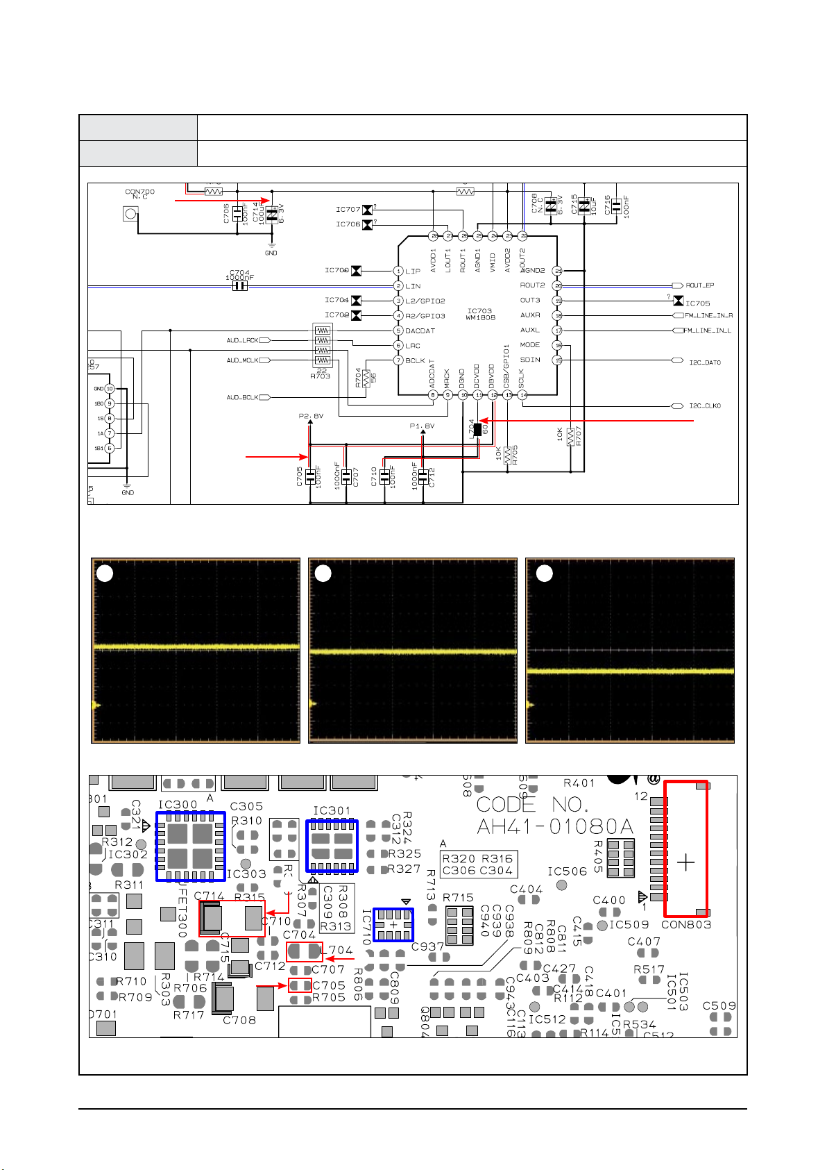
Samsung Electronics 4-5
Troubleshooting
Test Point C714 → 3.1V, C705 → 2.8V, L704 → 1.8V
Result Check each output terminal.
Audio CODEC Page, 7-7
CON803
IC300
IC710
IC403
IC301
PCB Bottom Page, 6-3
<Table 4-2>
21 3
2
1
3
1
3
2
 Loading...