

SAMSUNG CW21A83NS8XEC, WS28W8VDESXXEC, CW28C93WS8XXEG, WS28W73WS8XXEG, WS32W74WS8XXEG Service Manual

COLOR TELEVISION RECEIVER
Chassis : KS3A(P) (REV. 2)
Model : CW21A83NS8XEC
WS28W8VDESXXEC
CW28C93WS8XXEG
WS28W73WS8XXEG
WS32W74WS8XXEG
COLOR TELEVISION RECEIVER CONTENTS
Precautions
Reference Information
Specifications
Alignment and Adjustments
Troubleshooting
Exploded Views and Parts List
Electrical Parts List
Block Diagrams
Wiring Diagram
Schematic Diagrams
1.
2.
3.
4.
5.
6.
7.
8.
9.
10.

ELECTRONICS
© Samsung Electronics Co., Ltd. SEP. 2001
Printed in Korea
3KS3A-SEH-0917

Reference Information
Samsung Electronics 2-1
2. Reference Information
2-1 Tables of Abbreviations and Acronyms
A
Ah
Å
dB
dBm
°C
°F
°K
F
G
GHz
g
H
Hz
h
ips
kWh
kg
kHz
kΩ
km
km/h
kV
kVA
kW
I
MHz
Ampere
Ampere-hour
Angstrom
Decibel
Decibel Referenced to One
Milliwatt
Degree Celsius
Degree Fahrenheit
degree Kelvin
Farad
Gauss
Gigahertz
Gram
Henry
Hertz
Hour
Inches Per Second
Kilowatt-hour
Kilogram
Kilohertz
Kilohm
Kilometer
Kilometer Per Hour
Kilovolt
Kilovolt-ampere
Kilowatt
Liter
Megahertz
MV
MW
MΩ
m
µA
µF
µH
µm
µs
µW
mA
mg
mH
mI
mm
ms
mV
nF
Ω
pF
Ib
rpm
rps
s
V
VA
W
Wh
Megavolt
Megawatt
Megohm
Meter
Microampere
Microfarad
Microhenry
Micrometer
Microsecond
Microwatt
Milliampere
Milligram
Millihenry
Milliliter
Millimeter
Millisecond
Millivolt
Nanofarad
Ohm
Picofarad
Pound
Revolutions Per Minute
Revolutions Per Second
Second (Time)
Volt
Volt-ampere
Watt
Watt-hour
Table 2-1 Abbreviations

Reference Information
2-2 Samsung Electronics
Table 2-2 Table of Acronyms
ABL
AC
ACC
AF
AFC
AFT
AGC
AM
ANSI
APC
APC
A/V
AVC
BAL
BPF
B-Y
CATV
CB
CCD
CCTV
Ch
CRT
CW
DC
DVM
EIA
ESD
ESD
FBP
FBT
FF
FM
FS
GND
G-Y
H
HF
HI-FI
IC
IC
IF
Automatic Brightness Limiter
Alternating Current
Automatic Chroma Control
Audio Frequency
Automatic Frequency Control
Automatic Fine Tuning
Automatic Gain Control
Amplitude Modulation
American National Standards Institute
Automatic Phase Control
Automatic Picture Control
Audio-Video
Automatic Volume Control
Balance
Bandpass Filter
Blue-Y
Community Antenna Television (Cable TV)
Citizens Band
Charge Coupled Device
Closed Circuit Television
Channel
Cathode Ray Tube
Continuous Wave
Direct Current
Digital Volt Meter
Electronics Industries Association
Electrostatic Discharge
Electrostatically Sensitive Device
Feedback Pulse
Flyback Transformer
Flip-Flop
Frequency Modulation
Fail Safe
Ground
Green-Y
High
High-Frequency
High Fidelity
Inductance-Capacitance
Integrated Circuit
Intermediate Frequency
I/O
L
L
LED
LF
MOSFET
MTS
NAB
NEC
NTSC
OSD
PCB
PLL
PWM
QIF
R
RC
RF
R-Y
SAP
SAW
SIF
SMPS
S/N
SW
TP
TTL
TV
UHF
UL
UV
VCD
VCO
VCXO
VHF
VIF
VR
VTR
VTVM
TR
Input/output
Left
Low
Light Emitting Diode
Low Frequency
Metal-Oxide-Semiconductor-Field-Effect-Tr
Multi-channel Television Sound
National Association of Broadcasters
National Electric Code
National Television Systems Committee
On Screen Display
Printed Circuit Board
Phase-Locked Loop
Pulse Width Modulation
Quadrature Intermediate Frequency
Right
Resistor & Capacitor
Radio Frequency
Red-Y
Second Audio Program
Surface Acoustic Wave(Filter)
Sound Intermediate Frequency
Switching Mode Power Supply
Signal/Noise
Switch
Test Point
Transistor Transistor Logic
Television
Ultra High Frequency
Underwriters Laboratories
Ultraviolet
Variable-Capacitance Diode
Voltage Controlled Oscillator
Voltage Controlled Crystal Oscillator
Very High Frequency
Video Intermediate Frequency
Variable Resistor
Video Tape Recorder
Vacuum Tube Voltmeter
Transistor

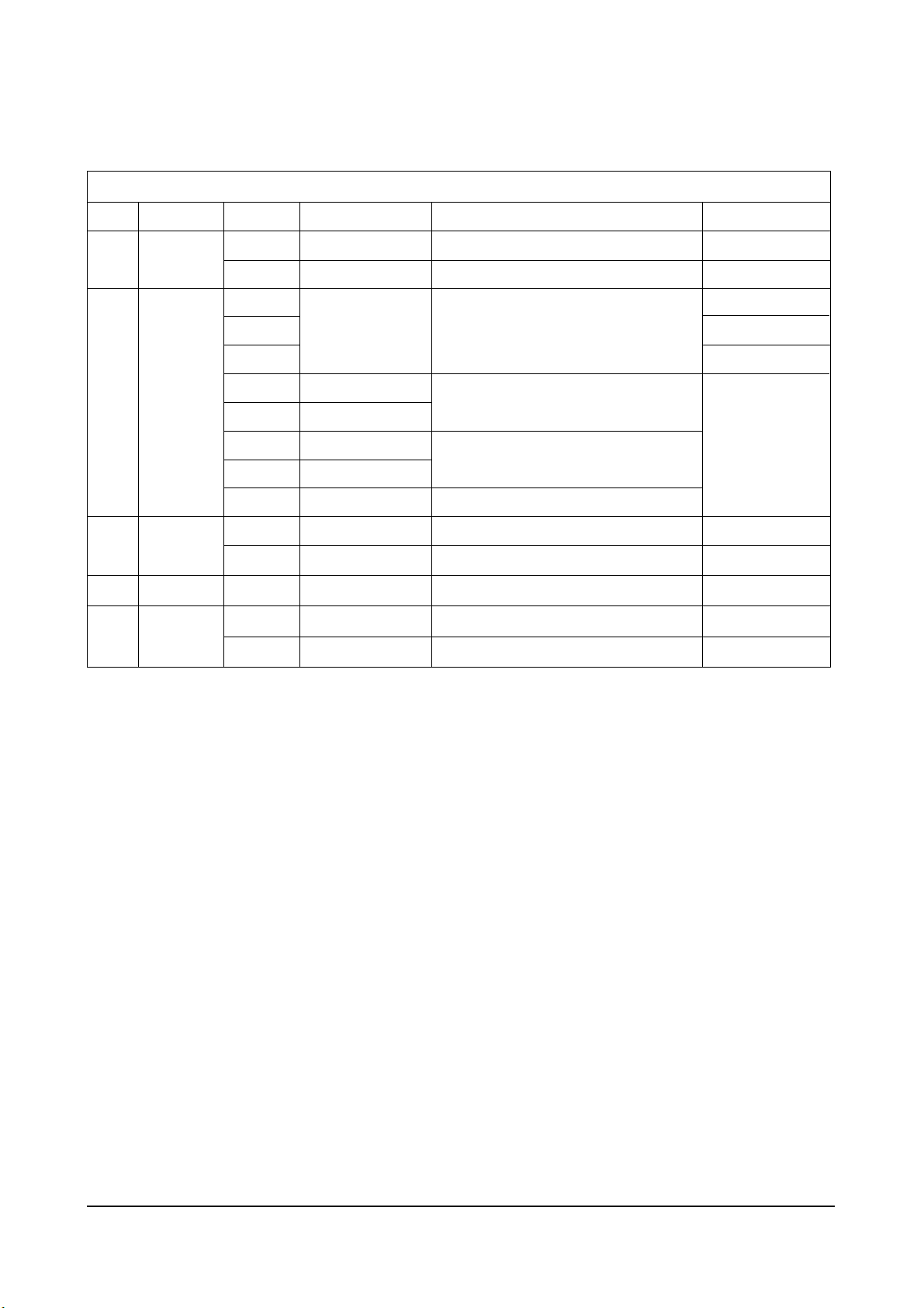
Table 2 - 3 IC Line - Up
NO
1
DESCRIPTION
Video Processor
Multistandard Sound Processor
MICOM, TTX(MTP)
EEPROM
Audio AMP
RGB Drive AMP Hybrid IC
100Hz Horizontal Pulse AMP
Vertical IC
Horizontal Drive IC
E/W Drive IC
SPS Controllor
Bridge Diode
Photo Coupler
5V Controlled Regulator
Rectifier Diode
3.3V Regulator
6V Regulator
8V Controlled Regulator
3.3V Regulator
MICOM Reset IC
IIC Level Shifter
Main Tuner with IF Block
Sub Tuner with IF Block
Reference Information
Samsung Electronics 2-3
2-2 IC Line Up
LOC. NO
IC201S
IC601
IC901
IC902
IC602
HIC201
HIC202
HIC203
HIC204
HIC401
IC301
Q402
Q401
D414
IC401
Q404
IC801S
D801S
PC801S
IC802
D805
D806
D807
D802
IC201
IC804
IC803
IC903
IC904
Q909
Q910
TU01S
TU02S
BOARD
MAIN
SPEC
VDP3112B
MSP3411G
SDA555X
KS24L161
TDA7297
DRGB001
DDRI001
LA7845
KSC2073-H2
KSD5703
FMP-3FU
KA393
IRF620
3S1265R
RBV606
PC123Y
KA78R05
FML-G12S
FMG-G2CS
KA78RM33
KA7806
KA78R08
KA78RM33
KIA7025AP
2N7000
TCLS3101PD09A9(S)
TCPN3081PD09A(S)
REMARK
Refer to Table 2-3-1
Refer to Table 2-3-2
Refer to Table 2-3-3
VM Option
Option
HC401
HC801
VDPY
Refer to Table 2-3-4
Refer to Table 2-3-5
2-4 Samsung Electronics
Table 2 - 3 IC Line - Up
NO
1
2
3
4
5
DESCRIPTION
Trans Switching
Trans FBT
Video Output AMP R.G.B Drive
Push-Pull (VM)
TR-Power (TILT)
OP-AMP (TILT)
OP-AMP
TR-Power
Video Switching IC with Adder Output
High-end Picture-In Picture IC
3.3V Regulator
LOC. NO
T801S
T444S
IC501
IC502
IC503
QF04
QF05
QG02
QG03
ICG01
ICH01
QH01
ICS01
ICP01
ICP02
SPEC
AA26-00046A
FUJ-29B001
TDA6111Q
2SC2344
2SA1011
KSA940
KSD2073-H2
KA4558
KA4558
2SC4636RB
TEA6425
SDA9489X
EZ1086CM
REMARK
Refer to Table 2-3-6
Refer to Table 2-3-7
Option
Option
Option
Option
BOARD
MAIN
CRT
DOUBLE
FOCUS
V-S/W
PIP
Reference Information

Reference Information
Samsung Electronics 2-5
SPEC
VDP3108B
VDP3112B
VDP3120B
VDP3130Y
VDP3140D
FUNCTION
50Hz Basic
50Hz, 2H Comb Filtr
50Hz, 2H Comb Filter, Horizontal Scaler
50Hz, 2H Comb Filter, DVD Input
100Hz
REMARK
Table 2-3-1 VIDEO IC (IC201S)
SPEC
MSP3400D
MSP3410D
MSP3411G
FUNCTION
Multistandard, A2 Stereo
Multistandard, A2 Stereo, Nicam
Multistandard, A2 Stereo, Nicam, Vitual Dolby
REMARK
SPEC
TDA7297
FUNCTION
15W x 2CH, 10W x 2CH
REMARK
SPEC
TCLS3101PD09A(S)
TCPS3001PD09D(S)
TCPS3001PD09E(S)
FUNCTION
CS with LNA Function
CS
CS
REMARK
Main
India
SPEC
TCPS3000PC09B(S)
FUNCTION
CS
REMARK
Sub
TCPS3001PD09A(S) is out-of-date, TCPS3001PD09D(S) which is up-to-date has the same function.
Table 2-3-2 SOUND IC (IC601)
Table 2-3-3 SOUND AMP (IC602)
Table 2-3-4 1’st TUNER (TU01S)
Table 2-3-5 2’nd TUNER (TU02S)
Note

Reference Information
2-6 Samsung Electronics
SPEC
FUJ-29B001
FUH-29A001B
FUNCTION
29”
21”
REMARK
Table 2-3-6 TRANS
SPEC
AA26-00046A
AA26-00044C
FUNCTION
29”
21”
REMARK
Table 2-3-7 TRANS FLYBACK (FBT)

Alignment and Adjustments
Samsung Electronics 4-1
4. Alignment and Adjustments
4-1 General Alignment Instructions
1. Usually, a color TV-VCR needs only slight
touch-up adjustment upon installation. Check
the basic characteristics such as height,
horizontal and vertical sync and focus.
2. Observe the picture for good black and white
details. There should be objectionable color
shading; if color shading is present,
demagnetize, perform purity and convergence
adjustments described below.
3. Use the specified test equipment or its
equivalent.
4. Correct impedance matching is essential.
5. Avoid overload. Excessive signal from a
sweep generator might overload the front-end
of the TV. When inserting signal markers, do
not allow the marker generator to distort test
results.
6. Connect the TV only to an AC power source
with voltage and frequency as specified on the
backcover nameplate.
7. Do not attempt to connect or disconnect any
wires while the TV is turned on. Make sure
that the power cord is disconnected before
replacing any parts.
8. To protect against shock hazard, use an
isolation transformer.
4-2 Automatic Degaussing
A degaussing coil is mounted around the
picture tube, so that external degaussing after
moving the TV should be unnecessary. But
the receiver must be properly degaussed upon
installation.
The degaussing coil operates for about 1
second after the power is switched ON. If the
set is moved or turned in a different direction,
the power should be OFF for at least 10
minutes.
If the chassis or parts of the cabinet become
magnetized, poor color purity will result. If
this happens, use an external degaussing coil.
Slowly move the degaussing coil around the
faceplate of the picture tube and the sides and
front of the receiver. Slowly withdraw the coil
to a distance of about 6 feet before turning
power OFF.
If color shading persists, perform the
following Color purity and Convergence
adjustments.
4-3 High voltage Check
CAUTION : There is no high voltage adjustment
on this chassis. The B+ power supply should be
+135 volts (with full color- bar input and normal
picture level).
1. Connect a digital voltmeter to the second
anode of the picture tube.
2. Turn on the TV. Set the Brightness and
Contrast controls to minimum (zero beam
current).
3. Adjust the Brightness and contrast controls to
both extremes. Ensure that the high voltage
does not exceed 32 KV under any conditions.

Alignment and Adjustments
4-2 Samsung Electronics
4-5 SCREEN Adjustment
1. Input Toshiba Pattern
2. Enter “Service Mode”.(Refer to “Service Mode”)
3. Select “G2-Adjust”.
4. Set the values as below.
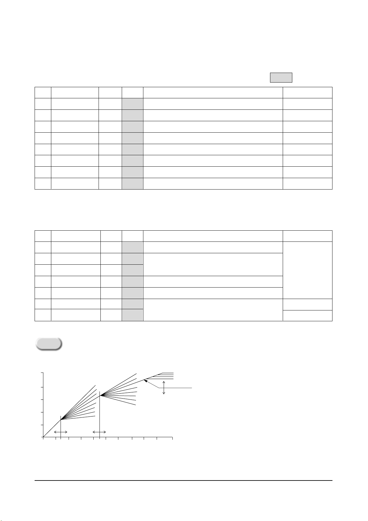
4-4 Dynamic Focus Adjustment
1. A dynamic focus adjustment should be done
after replacing the CRT PCB, FBT or CRT.
2. Input a crosshatch pattern.
3. Enter “ STANDARD “ in video mode.
4. Turn the Dynamic focus VR fully clockwise
(maximum).( )
5. Turn the Static focus VR fully
counterclockwise (maximum).( )
6. Slowly turn the static focus VR
counterclockwise. Adjust until the
vertical line in the middle of the screen
has maximum clarity.( )
7. Slowly turn the dynamic focus VR (clockwise)
and adjust the 3rd horizontal line for
maximum clarity.( )
8. Repeat 4-7, if necessary.
❷
❶
❷
❶
❷
❶
❷
❶
29 Inch
IBRM = 220
WDRV = 35
CDL = 220
COLR G B = 150 150 150
21 Inch
IBRM = 220
WDRV = 35
CDL = 165
COL = 70
STATIC FOCUS VR
H
DYNAMIC FOCUS VR
V
SCREEN
<FBT FOCUS PACK>

Alignment and Adjustments
Samsung Electronics 4-3
5. Turn the SCREEN VR until “MRCR G B” and “MRWDG” are green and those value are about 100.
(The incorrect SCREEN Voltage may result that “MRCR G B” and “MRWDG” should be red)
When you do not have Toshiba Pattern, follow this method.
1. Set the TV on the condition that AV mode no signal(black)
2. Enter the “Menu” and set the mode to blue screen off.
3. Enter the “Service Mode”.
4. Select “ G2-Adjust”.
5. Set the values as below.
IBRM = 220
WDRV = 35
CDL = 220
COLR G B = 150 150 150
6. Turn the SCREEN VR until the value of “ MRCR G B” is about 120. Do not mind that
the “OSD” Color is red.
■ After completing G2-Adjust, follow this procedure.
① Enter the “Video Adjust 1”.
➁ Choose any item in menu. (ex. Select “Red Cutoff”)
➂ Change the value of item you select, and recover the value.
For example, when the value of “Red Cutoff” is 127, change the value to 128 and restore
the value to 127.
If you do not follow this procedure, the picture may be abnormal.
For example, when the TV set is on, the picture becames brighter gradually.
Note 1.

Alignment and Adjustments
4-4 Samsung Electronics
4-6 E2PROM (IC902) Replacement
1. When IC902 is replaced, all adjustment data revert to the initial values.
So, all adjustment values when servicing should be readjusted.
2. After IC902 is replaced, connect the AC power supply cord.
3. Turn the power switch ON.
4. In stand-by, warm up the TV for at least 10 seconds.
5. Power on the TV.
4-7 White Balance Adjustment
■ Equipment : Color-Analyzer (CA-100)
■ Input Signal : Pattern signal (Toshiba pattern)
1. Select STANDARD from the menu.
2. Input an 100% White pattern.
3. Enter the “Service Mode”. (Refer to “4-8 Service Mode”)
4. Warm up the TV set at least for 30 minutes.
5. Input a Toshiba pattern signal.
6. Enter the “Video Adjust1”.
- Adjust “Sub Contrast” so that Y (luminance) becomes 40 ft ± 3.
- Use “Red Drive” and “ Blue Drive” to adjust High-Light (x : 290, y : 300)
- Adjust “Sub Bright” so that Y (luminance) becomes 1.3ft ± 0.3.
- Use “Red Cutoff” and “Blue Cutoff” to adjust Low-Light (x : 290, y : 300).
7. Adjust CA-100 so that the final adjustment value can be fixed.
8. Use the Channel Up/Down (▲/▼) buttons to move the cursor on the adjustment modes.
9. Use the Volume +/- buttons to change the adjustment value.

Alignment and Adjustments
Samsung Electronics 4-5
4-8 Factory Adjustment
1. To enter the “Service Mode”, Press the remote-control keys in this sequence :
- If you do not have Factory remote-control
- If you have Factory remote-control
2. After the Service Mode is entered, the initial screen is as shown in the figure below.
3. Use the Channel Up/Down buttons to move the cursor in the adjustment parameters.
- When CRT, CRT PCB, FBT, E
2
PROM (sometimes MICOM) is replaced, the adjustment values
should be controlled.
- After the Service adjustment is completed, Do not select “Reset” in the service mode menu.
(After above procedure is done, power is on initially and the “Plug and Play” will be operated.)
4-8-1 Service Mode
*
These hexa digits are check sum value which
depends on the MICOM.
If check sum value is changed, the value of
E
2
PROM Data newly initialed.
Note 2.
PICTURE OFF PICTURE ON
DISPLAY
()
MENU
MUTE
PICTURE ON
Service
Deflection
Video Adjust 1
Video Adjust 2
Video Adjust 3
Option(81h 0Ch)
Reset
G2-Adjust
Others
DISPLAY
*
()
FACTORY

Alignment and Adjustments
4-6 Samsung Electronics
Initial
Value
-30
-7
-3
-17
73
-47
-7
13
23
13
8
0
26
23
30
6
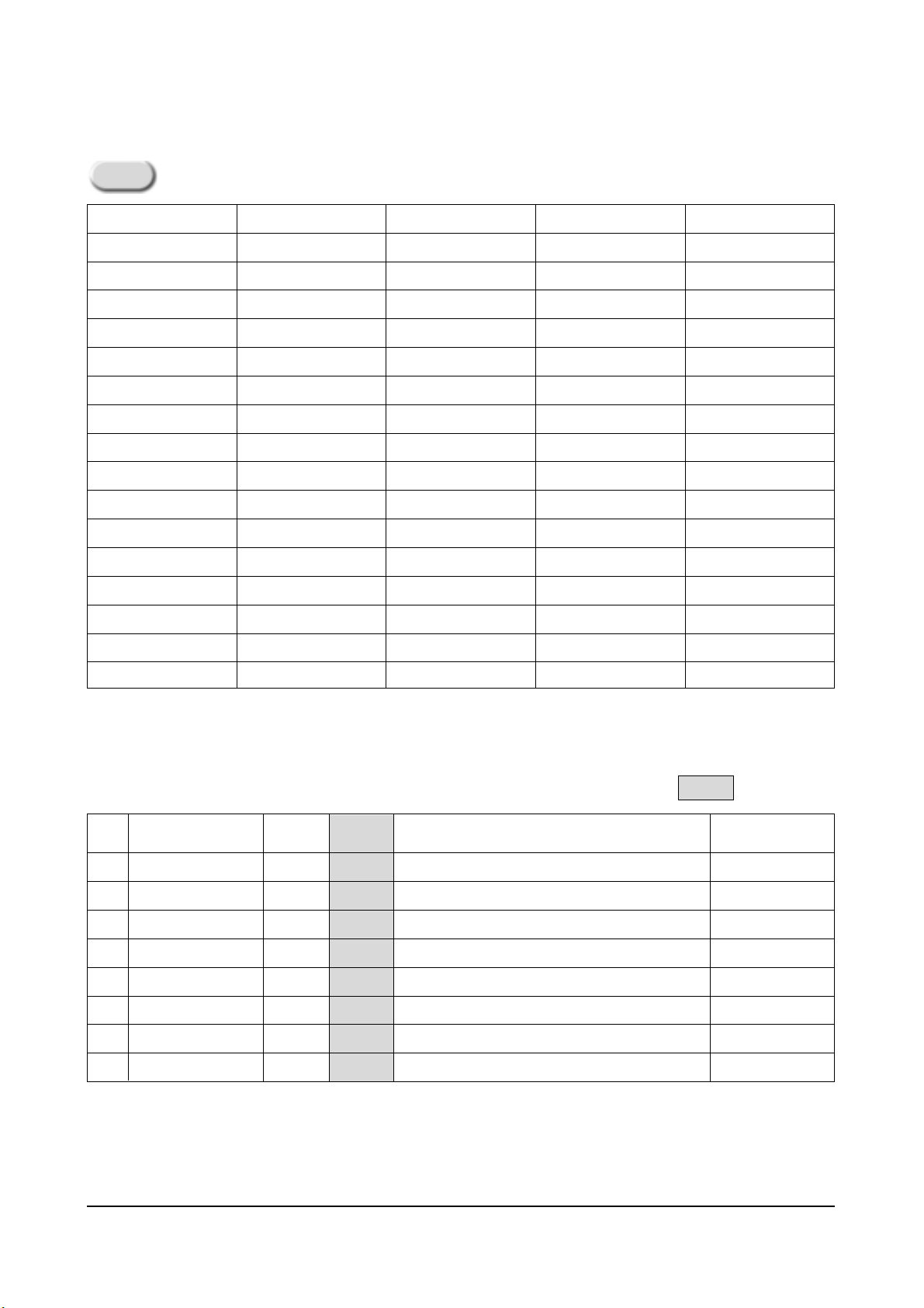
4-8-2 Memory Data
4-8-2(A) DEFLECTION (GEOMETRIC ADJUSTMENT VALUE)
No.
1
2
3
4
5
6
7
8
9
10
11
12
13
14
15
16
OSD
V Shift
V Amp
V Slope
V SC
H EW
H Trapizium
H Parabola
H Symmetry
H Corner
H Shift
PIP Contrast
PIP Tint
PIP PAL V Pos
PIP NTSC V Pos
PIP H Pos
PIP BLKLG
Range
-128 ~127
-128 ~127
-128 ~127
-128 ~127
-128 ~127
-128 ~127
-128 ~127
-128 ~127
-128 ~127
-128 ~127
0 ~ 15
0 ~ 63
0 ~ 255
0 ~ 255
0 ~ 255
0 ~ 15
Function
Adjust Vertical Picture Position
Adjust Vertical Picture Size
Adjust Vertical Slope Correction
Adjust Vertical S-Correction
Adjust Horizontal Picture Size
Adjust Horizontal Trapeziod
Adjust Horizontal Parabola Wave
Adjust Horizontal Symmetry
Adjust Horizontal Corner
Adjust Horizontal Position
Adjust PIP Contrast
Adjust PIP Tinit
Adjust PIP Vertical Position (Main Picture is PAL)
Adjust PIP Vertical Position (Main Picture is NTSC)
Adjust PIP Horizontal Position
Adjust PIP Green Cutoff Level
Remark
Not to be adjusted
Not to be adjusted
Fixed Value

Alignment and Adjustments
Samsung Electronics 4-7
4-8-2(B) SCREEN CHANGE (I2C BUS GEOMETRIC ADJUSTMENT)
1 V Shift
V Slope
2
3 H EW
6 V Amp
V SC
7
8
H Trapizium
4 H Parabola
5 H Corner
9
10
H Shift
H Symmetry

Alignment and Adjustments
4-8 Samsung Electronics
4-8-2(C) VIDEO ADJUST 1
No.
1
2
3
4
5
6
7
8
9
10
11
12
13
14
15
OSD
Red Cufoff
Green Cutoff
Blue Cutoff
Red Drive
Green Drive
Blue Drive
Sub Bright
Sub Contrast
Sub Color
Sub Tint
BCL Threshold
BCL Gain
BCL Time
TTX Contrast
YC Delay
Range
0 ~255
0 ~255
0 ~255
0 ~255
0 ~255
0 ~255
0 ~ 200
0 ~ 13
0 ~ 27
0 ~ 100
0 ~ 255
0 ~ 15
0 ~ 15
0 ~ 255
0 ~ 8
Function
Adjust Red Cutoff Level
Adjust Green Cutoff Level
Adjust Blue Cutoff Level
Adjust Red Output Gain
Adjust Green Output Gain
Adjust Blue Output Gain
Adjust Brightness Level
Adjust Contrast Level
Adjust Color Level
Adjust Tint
Adjust Beam Control Limit
Refer to Note 3
Adjust OSD/TTX Contrast
Refer to Table 1
Remark
Low Light
High Light
Low Light
High Light
Not to be adjusted
WDRGB
BCL THESHOLD
1.8mA
1.6mA
MIN
BCL GAIN
MAX
Table 1. YC Delay Adjustment Table
YC
Delay
Value
PAL
Def.
4
BG
3
DK
6
I
6
L
7
Def.
1
BG
1
DK
5
I
8
L
5
SECAM
Def.
4
Fixed Value
Beam Control Limit Characteristic
Note 3.
Initial
Value
127
127
127
127
127
127
100
50
27
80
65
8
9
90
*
M
3
NTSC
The “Def.” means that TV is in AV mode.
✐
beam
50
IRE
Initial
Value
185
4
255
0
0
33
39
Alignment and Adjustments
Samsung Electronics 4-9
OSD
B stretch-BTHR
B stretch-BTLT
B stretch-BAM
Coring
RGB Bright
RGB Contrast
EHT Time
EHT Compensation
✐
4-8-2(E) VIDEO 3 ADJUST
No.
1
2
3
4
5
6
7
OSD
Peak Threshold
Soft Limit Slope B
Hard Limit
Peak Video Ref
Peak Video Gain
ACC-REF(PAL/NTSC)
ACCR(SECAM)
Range
0 ~ 255
0 ~ 15
0 ~ 255
0 ~ 4
0 ~ 5
0 ~ 40
0 ~ 39
Function
White Peak Level Threshold
Refer to Picture Below
White Peak Level Threshold Reference
White Peak Level Threshold Gain
Auto Color Control
Remark
Refer to Note
Below
No.
1
2
3
4
5
6
7
8
Range
0 ~ 55
0 ~ 15
0 ~ 31
10 ~ 31
0 ~ 255
0 ~ 255
0 ~ 15
0 ~ 255
Initial
Value
50
8
4
20
45
15
0
90
Function
Black Stretch Threshold
Black Stretch Tilt Position
Black Stretch Amount
Luma Peaking Filter Coring
OSD/TTX RGB Bright
OSD/TTX RGB Contrast
Electronic High Tension Response Time
Electronic High Tension Coefficient
Remark
Coring : The Value of Center Frequency for the active bandwidth.
4-8-2(D) VIDEO 2 ADJUST
✐
“Soft Limit” is that Limitting
the peak white without
feed-back, but “Peak Limit” is
that with feed-back for white
peak level
✐
Soft Limit & Hard Limit
Note 4.
Fixed Value
Output
511
400
300
200
100
0
0
Part 1 Part 2
tilt 1 [0...511]
100 200 300 400 500 600 700 800 900 1023
Slope 1 [0...15]
0
2
4
6
8
10
12
14
tilt 2 [0...511]
10
Slope 2 [0...15]
0
2
4
6
8
12
14
Hard limiter
Soft Limit Slope B
range=256...511
Li

Initial Value : Refer to Note 6 on the next page.
Alignment and Adjustments
4-10 Samsung Electronics
4-8-2(E) OPTION
No.
1
2
3
4
5
6
7
8
9
10
11
12
13
14
OSD
Language
Sound
CRT
AV Mode
X-Ray
Tilt Control
Auto FM
PIP
Txt Language
LNA
Equalizer
High Deviate
TTX On/Off
AV by CH key
Function
Arab, Iran, Lybya, CIS
A2/NICAM, V-Dolby, Mono, L-Stereo
4:3, Wide, Q(12.8:9), 4:3-16:9, Q-16:9
2Scart, 2Scart+S, 1RCA, 2RCA, 2RCA+S,
2RCA+D, 2RCA+S+D, 1Scart
Off, On
Off, On
Off, On
2-Tuner, 1-Tuner, Off
Arabic, Farsi, Arab-Hebrew, West Europe,
East Europe, Russian, Greek-Turkey
Off, On
Off, On
Off, On
Off, On
Off, On
Remark
OSD Language
Depending on IC601
Refer to Note 5
S:S-VHS, D:DVD
When PIP is “2-Tuner”,
set to “ON”
Without “TV/VIDEO”
key in the front panel,
set to “On”
Sound
A2/NICAM
V-DOLBY
Mono
L-Stereo
IC601
MSP3400D, MSP3410D
MSP3411G
Not used this mode for KS3A Chassis
Note 5.
Initial
Value
Fixed Value
✐
✐
Initital
Value
98
0
8
-15
6
BG
2
8
Alignment and Adjustments
Samsung Electronics 4-11
OSD
VSU
H QEW
H ZOOM Parabola
H 16:9 Parabola
TTX H Shift
Mono Sound System
V Slice Level
Melody Volumn
No.
1
2
3
4
5
6
7
8
Range
96 ~ 111
-30 ~ 30
-30 ~ 30
-30 ~ 30
-30 ~ 30
BG/DK/I/M
0 ~ 3
0 ~ 20
Function
Vertical Set Up Time
Adjust Horizontal Parabola in Zoom Mode
Adjust Horizontal Parabola in 16:9 Mode
Adjust Horizontal OSD/TTX Position
Adjust Melody Volumn
Remark
4-8-2(F) OTHERS
Fixed Value
Description
LANGUAGE
SOUND
CRT
AV MODE
X-RAY
TILT CONTROL
AUTO FM
PIP
TEXT LANGUAGE
LNA
EQUALIZER
HIGH DEVIATE
TTX ON/OFF
AV BY CH KEY
OPTION BYTE
Note 6.
CS29A5WT8X/UMG
Initial Vaue
Arab
V-Dolby
4:3
2 RCA + S
OFF
ON
ON
OFF
Arabic
OFF
ON
ON
ON
ON
84 CC D8
CS29A6PF8X/HAC
Initial Vaue
Arab
V-Dolby
4:3
2 RCA + S
OFF
ON
ON
2-Tuner
Farsi
ON
ON
ON
ON
OFF
85 DC 5E
CS29A6WT8X/BWT
Initial Vaue
CIS
A2/Nicam
4:3
2 SCART + S
OFF
ON
ON
OFF
RUSSIAN
OFF
ON
ON
ON
OFF
83 AC 28
CS29A5MT9X/BWT
Initial Vaue
CIS
A2/Nicam
4:3
2 SCART + S
OFF
ON
ON
2-Tuner
RUSSIAN
ON
ON
ON
ON
ON
83 AC AE
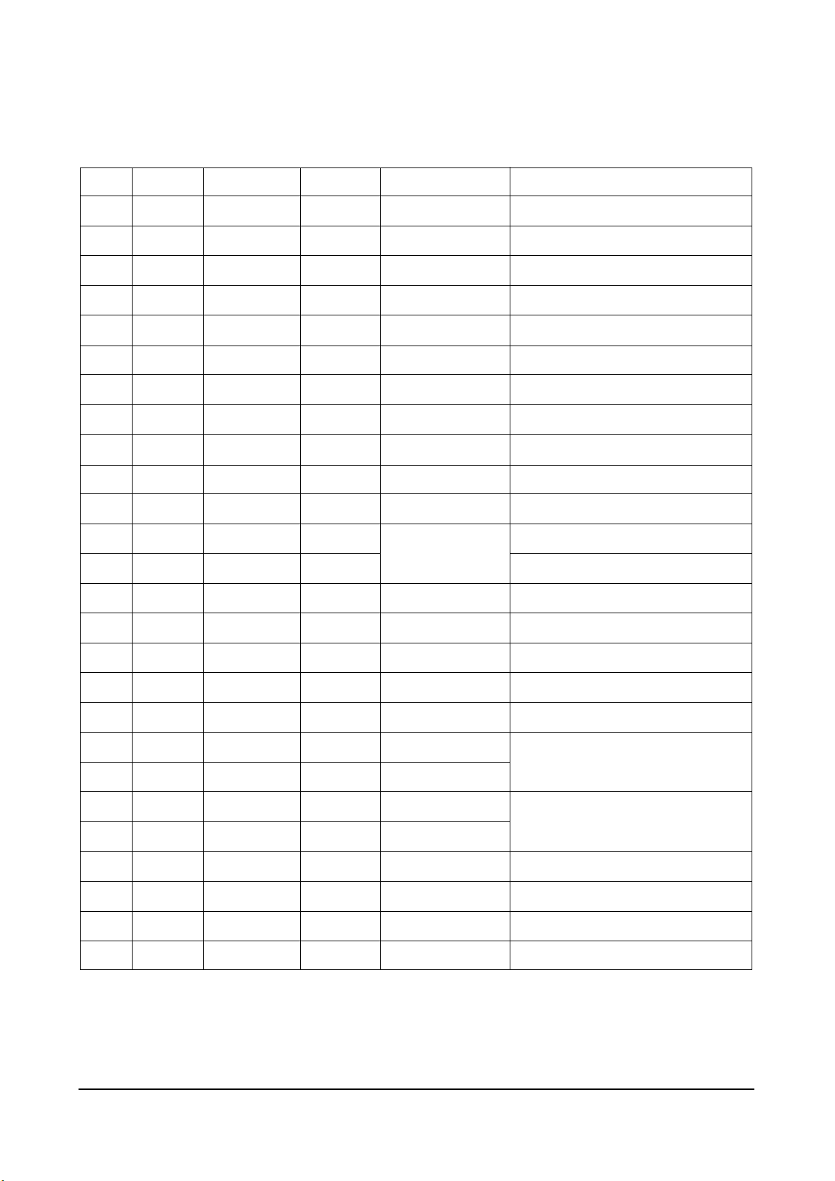
Option.

4-9-1 Pin Layout
Alignment and Adjustments
4-12 Samsung Electronics
4-9 MICOM
Write Protect
EEPROM SDA
EEPROM SCL
Bus-Stop
Main SDA
Main SCL
Sound Reset
Video Reset
VDD 2.5V
GND
VDD 3.3V
CVBS Input
VDD 2.5V
GND
AFT
Scart1 Ident
Scart2 Ident
Key 1
H-Sync
V-Sync
Key 3
Key 2
X-Ray Protect
IR Input
Stand-By LED
Time LED
1
2
3
4
5
6
7
8
9
10
11
12
13
14
15
16
17
18
19
20
21
22
23
24
25
26
I/O
I/O
IO
I/O
I/O
I/O
I/O
I/O
ADC
ADC
ADC
ADC
I/O
I/O
I/O
I/O
I/O
I/O
S
D
A
5
5
5
X
PWM
I/O
I/O
I/O
52
51
50
49
48
47
46
45
44
43
42
41
40
39
38
37
36
35
34
33
32
31
30
29
28
27
Tilt
N.C.
Power
Sound Mute
N.C.
N.C.
PX. Y
PX. Y
VDD 3.3V
GND
VDD 2.5V
CORE
OSD-B
OSD-G
OSD-R
VDD 2.5V
GND
X-TAL Out
X-TAL In
MICOM Reset
N.C.
N.C.
VDD 3.3V
GND
N.C.
Relay

Alignment and Adjustments
Samsung Electronics 4-13
4-9-2 Pin Assignment Specification
DESCRIPTION
EEPROM Write Protection
EEPROM Serial Data Line
EEPROM Serial Clock Line
Disable Micom IIC
Peripheral IC Serial Data Line
Peripheral IC Serial Clock Line
MSP IC Initial Control
VDP IC Initial Control
TTX CVBS Input
Analog B+
Analog Ground
Auto Fine Tuning Control
Scart1 Ident
Scart2 Ident
Key1 Input
Horizontal Sync Input
Vertical Sync Input
Key3 Input
Key2 Input
X-Ray Protection
Remocon Signal Input
LED Drive Output(Red)
LED Drive Output(Green)
PIN NO
1
2
3
4
5
6
7
8
9
10
11
12
13
14
15
16
17
18
19
20
21
22
23
24
25
26
FUNCTION
I/O
I/O
I/O
I/O
I/O
I/O
I/O
I/O
Vdd
GND
Vdd
CVBS
Vdd
GND
ADC
ADC
ADC
ADC
HS
VS
I/O
I/O
I/O
I/O
I/O
I/O
ASSIGN
Write Protect
ROM SDA
ROM SCL
Bus Stop
Main SDA
Main SCL
Sound Reset
Video Reset
VDD 2.5V
VDD 3.3V
CVBS Input
VDD 2.5V
AFT
SC1-ID
SC2-ID
Key1
H-Sync
V-Sync
Key3
Key2
X-Ray
IR-In
STD-LED
TIM-LED
IN/OUT
Out
I/O
I/O
In
I/O
I/O
Out
Out
In
In
In
In
In
In
In
In
In
In
In
Out
Out
ACTIVE H/L
Low
Low
Low
Low
Alignment and Adjustments
4-14 Samsung Electronics
4-9-2 Pin Assignment Specification (Continued)
PIN NO
27
28
29
30
31
32
33
34
35
36
37
38
39
40
41
42
43
44
45
46
47
48
49
50
51
52
FUNCTION
I/O
N.C.
GND
Vdd
N.C.
N.C.
Reset
X-In
X-Out
GND
Vdd
R
G
B
COR
Vdd
GND
Vdd
I/O
I/O
N.C.
N.C.
I/O
I/O
N.C.
I/O
ASSIGN
Relay
VDD 3.3V
Reset
X-TAL In
X-TAL Out
VDD 2.5V
OSD-R
OSD-G
OSD-B
CORE
VDD 2.5V
VDD 3.3V
PX.Y
PX.Y
S-Mute
Power
Tilt
IN/OUT
Out
In
In
Out
Out
Out
Out
Out
In
Out
Out
Out
Out
ACTIVE H/L
Low
Low
6MHz
6MHz
High
Low
PWM
DESCRIPTION
Activate Degausssing Coil
Not Used (Programmed Gound Level)
Analog Ground
Not Used (Programmed Gound Level)
Not Used (Programmed Gound Level)
Micom Hardware Reset
Crystal Oscillation Input
Crystal Oscillation Output
Analog Ground
Analog B+
OSD/TTX Output (Red)
OSD/TTX Output (Green)
OSD/TTX Output (Blue)
Fast Blank/Half Contrast Output
When The Caption Function Adopted, Used.
Not Used (Programmed Gound Level)
Sound Amp Mute
Picture On/Off Control
Not Used (Programmed Gound Level)
Tilt Control Output
 Loading...