

Page 1
WASHING MACHINE
DRUM TYPE
Basic Model : Q1657
(TS EURO PROJECT)
Model Name : WF8800*
SERVICE
WASHING MACHINE (DRUM) CONTENTS
WF8700*
WF8802*
WF8804*
WF8814* WF8714*
WF8754*
(HEBA PROJECT)
WF8702*
WF8704*
Manual
WF8802DPF WF8702LSV
1. Safety Instructions
2. Features and Specifications
3. Disassembly and Reassembly
4. Troubleshooting
5. PCB Diagram
6. Wiring Diagram
7. Schematic Diagram
8. Reference Information
Refer to the service manual in the GSPN (see the rear cover) for the more information.
Page 2

CONTENTS
1. Safety instructions . . . . . . . . . . . . . . . . . . . . . . . . . . . . . . . . . . . . . . . . . . . . . . . . . . . . . . . . . . . . . . . . . . . 1
1-1. Safety instructions for service engineers . . . . . . . . . . . . . . . . . . . . . . . . . . . . . . . . . . . . . . . . . . . . . . .1
2. Features and Specifications . . . . . . . . . . . . . . . . . . . . . . . . . . . . . . . . . . . . . . . . . . . . . . . . . . . . . . . . . . . 5
2-1. Features . . . . . . . . . . . . . . . . . . . . . . . . . . . . . . . . . . . . . . . . . . . . . . . . . . . . . . . . . . . . . . . . . . . . . . . .5
2-2. Specifications . . . . . . . . . . . . . . . . . . . . . . . . . . . . . . . . . . . . . . . . . . . . . . . . . . . . . . . . . . . . . . . . . . . .8
2-3. Comparing specifications with existing models . . . . . . . . . . . . . . . . . . . . . . . . . . . . . . . . . . . . . . . . . .9
2-4. Options specifications . . . . . . . . . . . . . . . . . . . . . . . . . . . . . . . . . . . . . . . . . . . . . . . . . . . . . . . . . . . . 10
3. Disassembly and Reassembly . . . . . . . . . . . . . . . . . . . . . . . . . . . . . . . . . . . . . . . . . . . . . . . . . . . . . . . . 11
3-1. Tools for disassembly and reassembly . . . . . . . . . . . . . . . . . . . . . . . . . . . . . . . . . . . . . . . . . . . . . . . 11
3-2. Standard disassembly drawings . . . . . . . . . . . . . . . . . . . . . . . . . . . . . . . . . . . . . . . . . . . . . . . . . . . .12
4. Troubleshooting . . . . . . . . . . . . . . . . . . . . . . . . . . . . . . . . . . . . . . . . . . . . . . . . . . . . . . . . . . . . . . . . . . . . 24
4-1. Error modes . . . . . . . . . . . . . . . . . . . . . . . . . . . . . . . . . . . . . . . . . . . . . . . . . . . . . . . . . . . . . . . . . . . .24
4-2. Corrective actions for each error code . . . . . . . . . . . . . . . . . . . . . . . . . . . . . . . . . . . . . . . . . . . . . . . .29
5. PCB diagram . . . . . . . . . . . . . . . . . . . . . . . . . . . . . . . . . . . . . . . . . . . . . . . . . . . . . . . . . . . . . . . . . . . . . . .35
5-1. Main PCB (Best: WF880*P* / WF870*P*) . . . . . . . . . . . . . . . . . . . . . . . . . . . . . . . . . . . . . . . . . . . . .35
5-2. Main PCB (Better: WF880*S* / WF870*S*) . . . . . . . . . . . . . . . . . . . . . . . . . . . . . . . . . . . . . . . . . . . .36
5-3. Circuit diagrams of main parts (Best: WF880*P* / WF870*P*) . . . . . . . . . . . . . . . . . . . . . . . . . . . . .37
5-4. Circuit diagrams of main parts (Better: WF880*S* / WF870*S*) . . . . . . . . . . . . . . . . . . . . . . . . . . . .38
5-5. Sub PCB (Best: WF880*P* / WF870*P*) . . . . . . . . . . . . . . . . . . . . . . . . . . . . . . . . . . . . . . . . . . . . . .39
5-6. Sub PCB (Better: WF880*S* / WF870*S*) . . . . . . . . . . . . . . . . . . . . . . . . . . . . . . . . . . . . . . . . . . . . .40
5-7. Detailed descriptions of contact terminals (sub PCB-Best: WF880*P* / WF870*P*) . . . . . . . . . . . . .41
5-8. Detailed descriptions of contact terminals (sub PCB-Better: WF880*S* / WF870*S*) . . . . . . . . . . . .42
6. Wiring diagram . . . . . . . . . . . . . . . . . . . . . . . . . . . . . . . . . . . . . . . . . . . . . . . . . . . . . . . . . . . . . . . . . . . . .43
6-1. Wiring diagram . . . . . . . . . . . . . . . . . . . . . . . . . . . . . . . . . . . . . . . . . . . . . . . . . . . . . . . . . . . . . . . . . .43
7. Schematic diagram . . . . . . . . . . . . . . . . . . . . . . . . . . . . . . . . . . . . . . . . . . . . . . . . . . . . . . . . . . . . . . . . .44
7-1. Main control (Best: WF880*P* / WF870*P*) . . . . . . . . . . . . . . . . . . . . . . . . . . . . . . . . . . . . . . . . . . .44
7-2. Main control (Better: WF880*S* / WF870*S*) . . . . . . . . . . . . . . . . . . . . . . . . . . . . . . . . . . . . . . . . . .45
7-3. Sub control (Best: WF880*P* / WF870*P*) . . . . . . . . . . . . . . . . . . . . . . . . . . . . . . . . . . . . . . . . . . . .46
7-4. Sub control (Better: WF880*S* / WF870*S*) . . . . . . . . . . . . . . . . . . . . . . . . . . . . . . . . . . . . . . . . . . .47
8. Reference . . . . . . . . . . . . . . . . . . . . . . . . . . . . . . . . . . . . . . . . . . . . . . . . . . . . . . . . . . . . . . . . . . . . . . . . .48
8-1. HEBA Project name . . . . . . . . . . . . . . . . . . . . . . . . . . . . . . . . . . . . . . . . . . . . . . . . . . . . . . . . . . . . . .48
Page 3
1. SAFETY INSTRUCTIONS
1-1. SAFETY INSTRUCTIONS FOR SERVICE ENGINEERS
► Make sure to observe the following instructions to operate the product correctly and safely and prevent possible
accidents and hazards while servicing.
► Two types of safety symbols, Warning and Caution, are used in the safety instructions.
Hazards or unsafe practices that may result in severe personal injury or death.
WARNING
Hazards or unsafe practices that may result in minor personal injury or property damage.
CAUTION
WARNING
• (When servicing electrical parts or harnesses) Make sure to disconnect the power plug before servicing.
Failing to do so may result in a risk of electric shock.
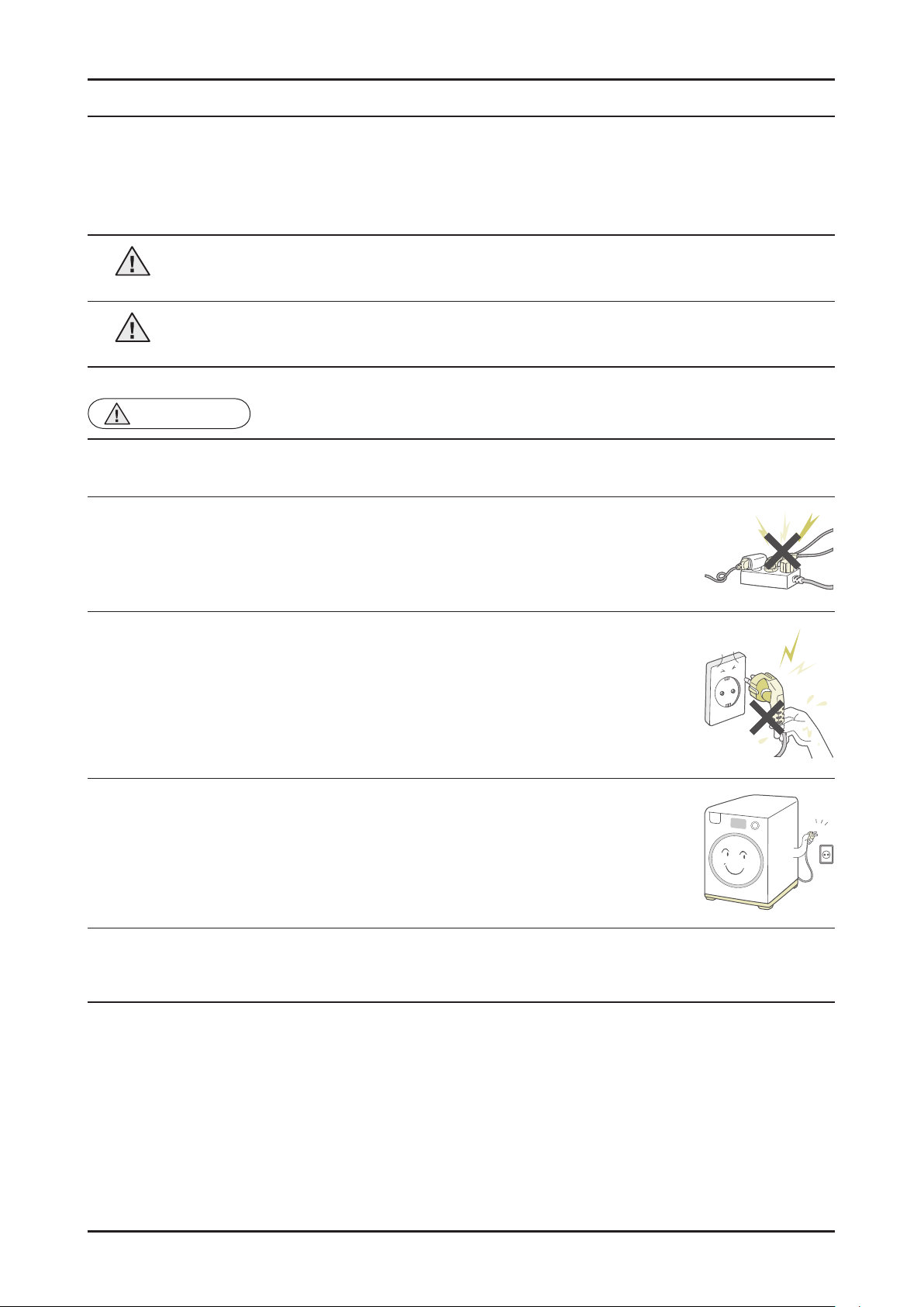
• Do not allow consumers to connect several appliances to a single power outlet at the
same time.
There is a risk of fire due to overheating.
• When removing the power cord, make sure to hold the power plug when pulling the plug
from the outlet.
Failing to do so may damage the plug and result in fire or electric shock.
• When the washing machine is not being used, make sure to disconnect the power plug
from the power outlet.
Failing to do so may result in electric shock or fire due to lightning.
BEFORE SERVICING
• Do not place or use gasoline, thinners, alcohol, or other fl
machine.
There is a risk of explosion and fire caused from electric sparks.
ammable or explosive substances near the washing
Safety Instructions _ 1
Page 4
2 _ Safety Instructions
WARNING
• Check if the power plug and outlet are damaged, flattened, cut or otherwise degraded.
If faulty, replace it immediately.
Failing to do so may result in electric shock or fire.
• Completely remove any dust or foreign material from the housing, wiring and connection parts.
This will prevent a risk of fire due to tracking and shorts in advance.
When connecting wires, make sure to connect them using the relevant connectors and check that they are
•
completely connected.
If tape is used instead of the connectors, it may cause fire due to tracking.
WHILE SERVICING
• Make sure to discharge the PBA
Failing to do so may result in a high voltage electric shock.
• When replacing the heater
If not inserted into the bracket-heater, it touches the drum and causes noise and electric leakage.
WARNING
• Check the wiring.
Ensure that no wire touches a rotating part or a sharpened part of the electrical harness.
• Check for any water leakage.
Perform a test run for the washing machine using the standard course and check whether there is any water
leakage through the floor section or the pipes.
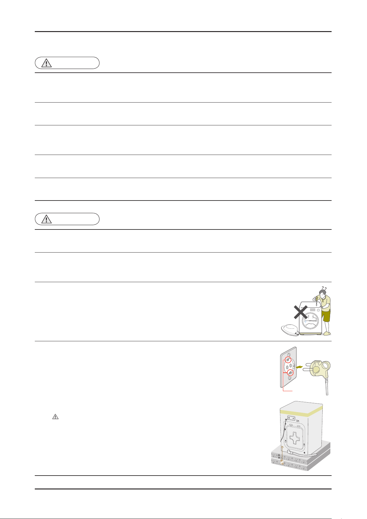
• Do not allow consumers to repair or service any part of the washing machine
themselves.
This may result in personal injury and shorten the product lifetime.
AFTER SERVICING
power terminals before starting the service.
, make sure to fasten the nut after ensuring that it is inserted into the bracket-heater.
• If it seems that grounding is needed due to water or moisture, make sure to run
grounding wires.
(Check the grounding of the power outlet, and additionally ground it to a metallic water
pipe.)
Failing to do so may result in electric shock due to electric leakage.
[Running a grounding wire]
Twist a grounding wire (copper wire) two or three times around the tap.
-
- If you connect the grounding wire to a copperplate, bury it 75 cm under the earth in a
place with a lot of moisture.
Do not connect the grounding wire to a gas pipe, plastic water pipe or telephone
wire. There is a risk of electric shock or explosion.
Grounding
terminal
75 cm
Copperplate
Page 5
CAUTION
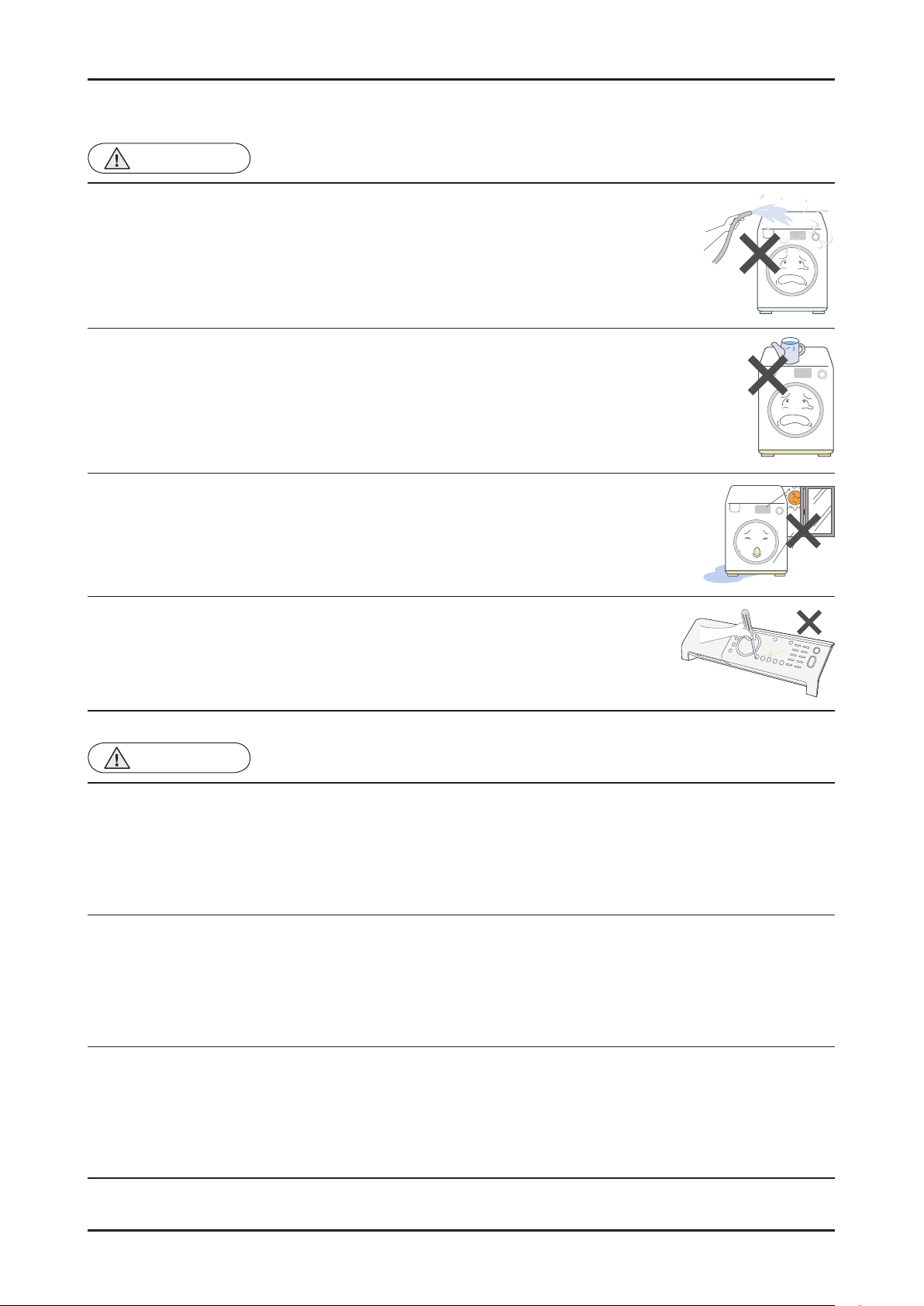
• Do not sprinkle water onto the washing machine directly when cleaning it.
This may result in electric shock or fire, and may shorten the product lifetime.
• Do not place any containers with water on the washing machine.
If the water is spilled, it may result in electric shock or fire. This will also shorten the
product lifetime.
Do not install the washing machine in a location exposed to snow or rain.
•
This may result in electric shock or fire, and shorten the product lifetime.
BEFORE SERVICING
• Do not press a control button using a sharp tool or object.
This may result in electric shock or damage to the product.
CAUTION
• When wiring a harness, make sure to seal it completely so no liquid can enter.
Make sure that they do not break when force is exerted.
• Check if there is any residue that shows that liquid entered the electric parts or harnesses.
If any liquid has entered into a part, replace it or completely remove any remaining moisture from it.
WHILE SERVICING
• If you need to place the washing machine on its back for servicing purposes, place a support(s) on the floor and lay it
down carefully so its side is on the floor
Do not lay it down on its front.
.
This may result in the inside tub damaging parts.
Safety Instructions _ 3
Page 6
CAUTION
• Check the assembled status of the parts.
They must be the same as before servicing.
• Check the insulation resistance.
Disconnect the power cord from the power outlet and measure the insulation resistance between the power plug
and the grounding wire of the washing machine. The value must be greater than 10MΩ when measured with a
500V DC Megger
AFTER SERVICING
• Check whether the washing machine is level in relationship with the floor
it is installed firmly on the floor.
Vibrations can shorten the lifetime of the product.
. Check whether
4 _ Safety Instructions
Page 7
2. FEATURES AND SPECIFICATIONS
2-1. FEATURES
COMMON FEATURES
Features Description
Implementing 8 kg in the
Standard Size
Addition of a Liquid
Detergent Tray
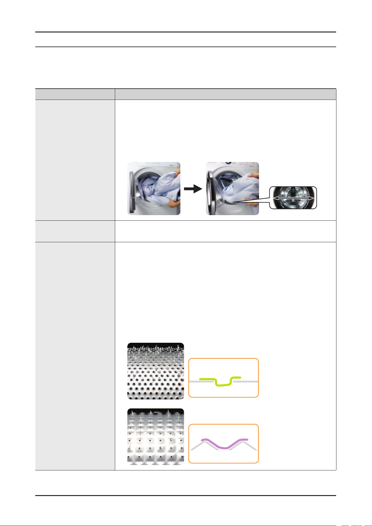
Diamond Drum • The washing performance has increased but potential damage to the washing has
• This is the maximum capacity to be implemented at the standard 60 cm depth.
- The benefits for customers have been greatly increased due to the efficient
use of limited space.
- Usability has been improved due to the easier loading and removing of the
laundry.
• The size of the loading entry has increased: 300 mm → 330 mm (Wide)
A lot more washing can be conveniently added and removed.
-
330 mm
• Usability has been improved due to the newly added Liquid Detergent Tray.
been minimized. (The size of the holes on the diamond drum has been reduced
for minimizing damage to the washing.)
- The embossed wall of the drum serves as a washboard, dramatically
increasing the washing performance compared with existing drum washing
machines, which use the power of the difference in elevation only
- The size of holes has been reduced drastically, maintaining the optimal wash
performance (Washing Cost 1.0) while saving on water and electricity required
for washing.
- The structure of the holes on the diamond drum has been changed minimizing
potential damage to the washing since it is difficult for strands to enter the
holes.
.
Conventional
Diamond Drum
Fabric
Fabric
Features and Specifi cations _ 5
Page 8
6 _ Features and Specifi cations
OPTIONAL FEATURES
► The features below depend on the model.
Features Description
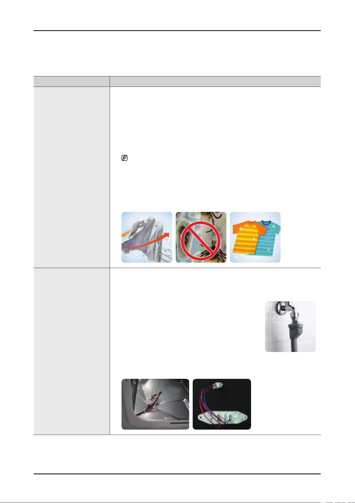
Air Refresh System • Sterilization/Deodorization/Removal of Ticks without Water Washing (Air Washing
Using Air and Heating)
Destroying bacteria and ticks without the use of water
-
- Removing the sweat and dirt odors
- Maintaining the shape and color of the washing without dry-cleaning
• Washing with air.
- Removing odors by heating, keeping the washing as new.
- Washing with air conveniently, compared with dry-cleaning
The goal of deodorization is 60 percent. (40-minute cycle)
• Washing one or two shirts in 30 minutes
- If a piece of clothes is not completely dry when it is humid, the machine can
dry it within 30 minutes
• Preventing bio-film caused by humidity from occurring
- You do not need to worry about the humidity inside the drum.
- The drum is dried regularly, preventing bio-film.
Water Safety System • The Water Safety System has invented for perfect leakage protection. The double
safety valve connects directly to the water faucet. In the event of a leakage,
the built-in sensor immediately detects the leak within a few short seconds,
automatically turning off both the water supply and the washing machine.
- Inlet hose
It attached to the water supply hose and automatically
cuts off water flow when hose damaged. It also
displays a warning indicator.
- Leakage Sensor
A water leakage sensor attached at the bottom of the washing machine to
cutoff the power automatically if a leakage occurs, to prevent danger of a fire.
Page 9
► The features below depend on the model.
Features Description
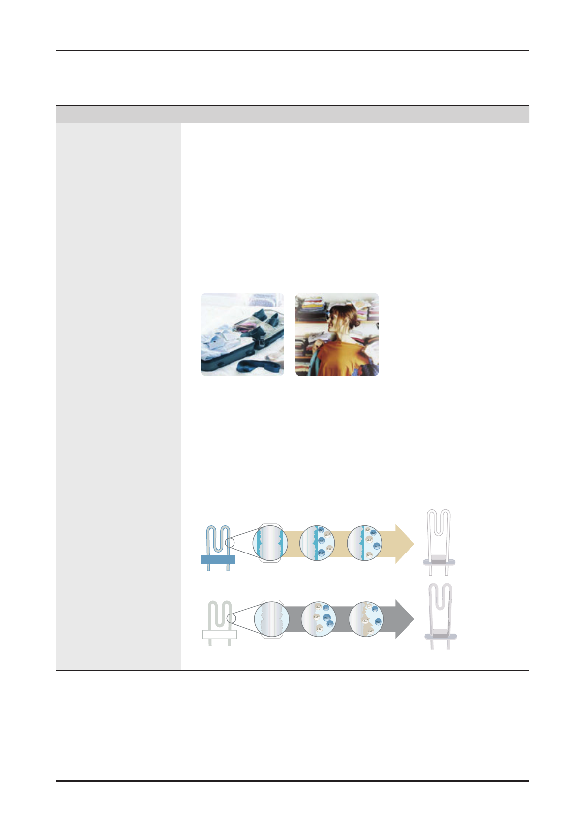
Silver Wash System • Samsung’s unique technology generates silver ions that remove bacteria and
fungi, and create an invisible shield that protects your clothes from unwanted
odors until your next wash. Using an ancient and proven purification technique so
simple, yet so advanced it removes microbes even in cold water.
• Effect of Silver W
ash System
- Keeps Stored Clothes Fresh
Ag+ Silver (Nano) Technology anti-bacterial effect keeps fabric free from
The
odor-causing micro-organisms for up to one month, without the use of strong
chemical cleaners. There’s no need to worry about musty-smelling clothes
even if they remain unused for a long period.
- Makes Shapeless Garments a
Thing of the Past
High temperatures and harsh bleaches can damage and discolor your clothes.
The Ag+ Silver (Nano) Technology helps your clothes last longer, without
stretching, shrinking, pilling or fading.
Ceramic Heater • The ceramic heater in Samsung washing machine prevents metals in hard water
from being attach to the heater, which may cause a reduction in heater efficiency.
It saves energy, time and costs.
- Energy Savings
Over time, conventional heaters increase their power consumption an average
of 5.8 percent, while ceramic heaters only become 1.8 percent less efficient.
- Time Savings
After three years, conventional heaters take 7.5 percent longer to heat up,
whereas ceramic only lose 2.5 percent longer to heat up, whereas ceramic
only lose 2.5 percent of their ability to heat up.
10 Years
Ceramic
Enlarged
iew
V
Producted
Surface
No Build-Up
2.7 Years
Normal
Enlarged
View
Molecules
binding
Scale
Formation
Features and Specifi cations _ 7
Page 10
8 _ Features and Specifi cations
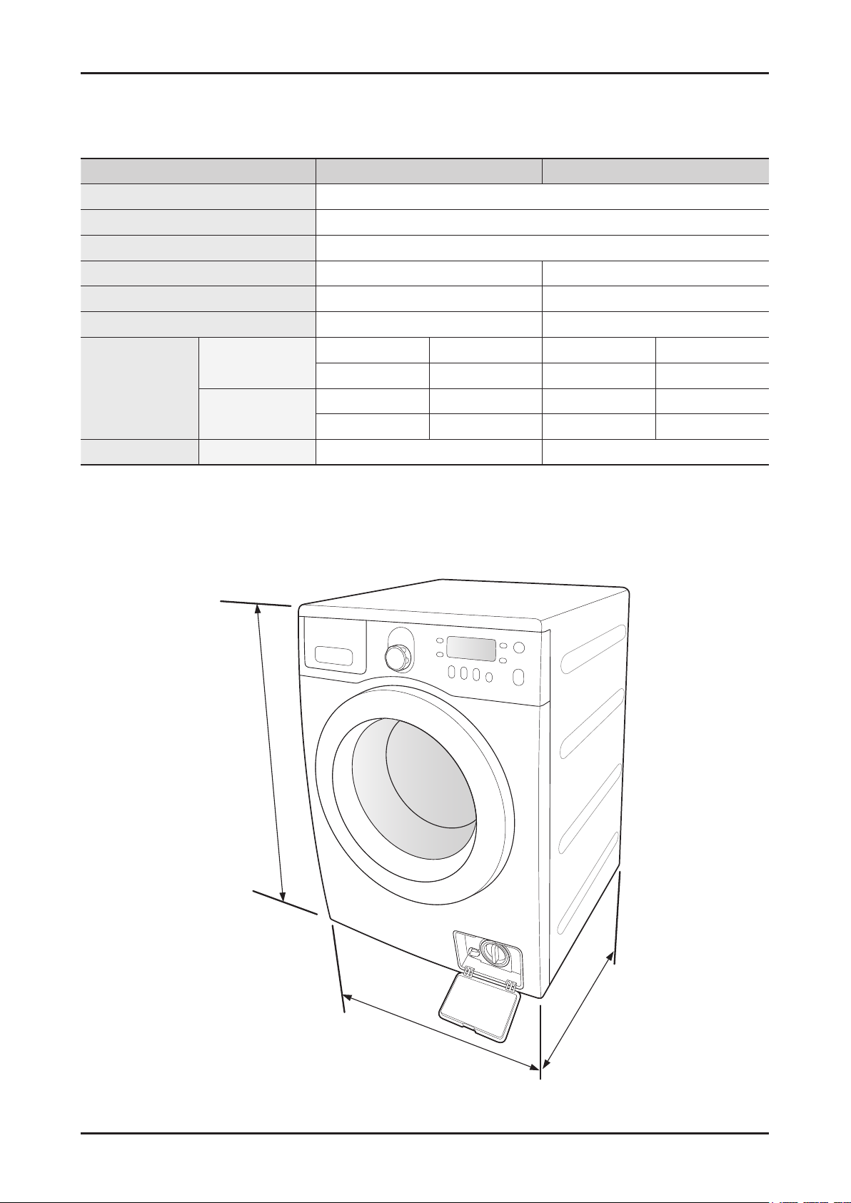
2-2. SPECIFICATIONS
Model WF8804*/WF8802*/WF8800* WF8704*/WF8702*/WF8700*
Wash Type FRONT LOADING TYPE
Dimension W 598 mm X D 600 mm X H 844 mm
Water Pressure 50 kPa ~ 800 kPa
Water Volume 64 ℓ 56 ℓ
Weight 74 kg / 73 kg / 72 kg 73 kg / 72 kg / 71 kg
Wash & Spin Capacity 8.0 kg 7.0 kg
WASHING
Power
Consumption
Spin Revolution rpm 1400 / 1200 / 1000 1400 / 1200 / 1000
WASHING and
TING
HEA
844
220 V 150 W 220 V 150 W
240 V 150 W 240 V 150 W
220 V 2000 W 220 V 2000 W
240 V 2400 W 240 V 2400 W
600
598
Page 11
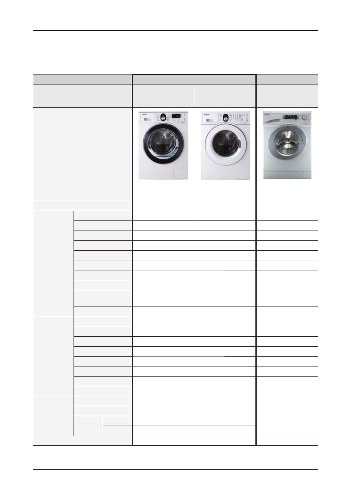
2-3. COMPARING SPECIFICATIONS WITH EXISTING MODELS
() : Functions may be different depending on the model.
Grade Heba TS euro
Model Name
Image
WF8804*/
WF8802*/
WF8800*
WF8704*/ 8754*
WF8702*/
WF8700*
Q1657
Feature
Capacity 8.0 kg 7.0 kg/7.5Kg(WF8754*) 7.5 kg
Drum Volume 64 ℓ 56 ℓ 57 ℓ
Max rpm 1400 / 1200 / 1000 1400 / 1200 / 1000 1600
Motor Universal 3 phase inverter
Control Sys General General
eight Detection 3 Stages No
W
Main Spec
USP
Design
Dimension (W X D X H mm) 598 x 600 x 844 600 x 600 x 850
Heater Capacity 2000 W / 230 V 2400 W /230 V
Water Supply Cold Only Cold and Hot Cold Only
Drainage Pump Pump
Power-Outage
Compensation
Zero Standby Power Y
Air Refresh
Silver Wash
Water Safety
Ceramic Heater
Diamond Drum Yes No
Loading Entry Size Wide (330 mm) 300 mm
Detergent
Installation Handle No No
Center Jog Dial Yes No
Display
Tray Powder/Liquid Powder Only
Big Door Yes (480 mm) No (400 mm)
High G.LED
Mid Dot Display
Diamond drum
Big door design
Yes Yes
es (1W or Less) No
Yes ()
Y
es () Y
()
Yes
Y
es ()
Silver wash
Wide G.LED
es ()
G.LED
No
No
No
Features and Specifi cations _ 9
Page 12
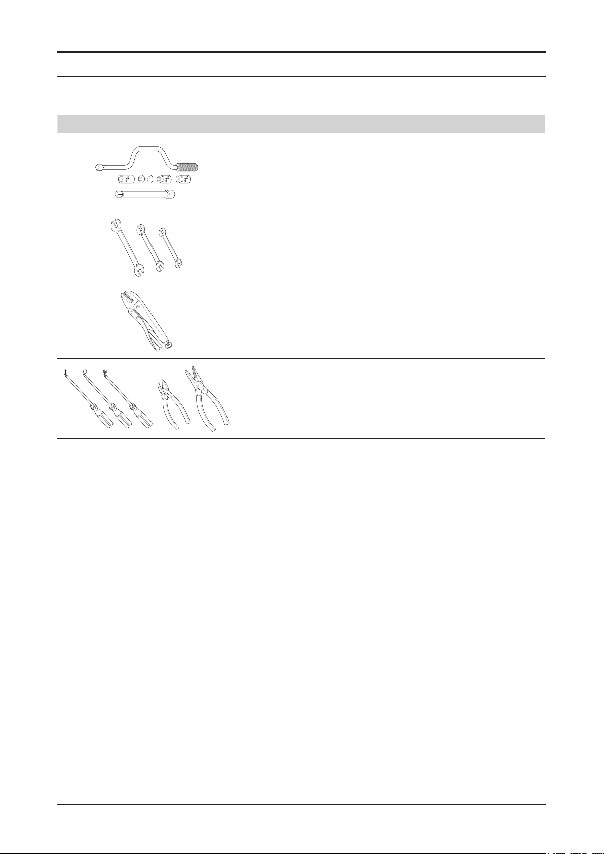
3. DISASSEMBLY AND REASSEMBLY
3-1. TOOLS FOR DISASSEMBLY AND REASSEMBLY
Tool Type Remarks
10mm
Box driver
Double-ended
spanner
Vice pliers
Others
(screwdriver, nipper,
long nose pliers)
13mm
19mm Pulley(1)
10mm
13mm
19mm
Heater(1),Tub(12), Fixer screw(5), Motor(2),
Balance(9)
Shock Absorber (2 holes each in left/right),
Damper(2), Damper(friction 2)
Replaced by box driver
Leg
A Tool for protecting empty turning of bolt or
abrasion from using box driver
For disassembly of Spin drum
Common tools for servicing
Removal and Reassembly _ 11
Page 13
12 _ Removal and Reassembly
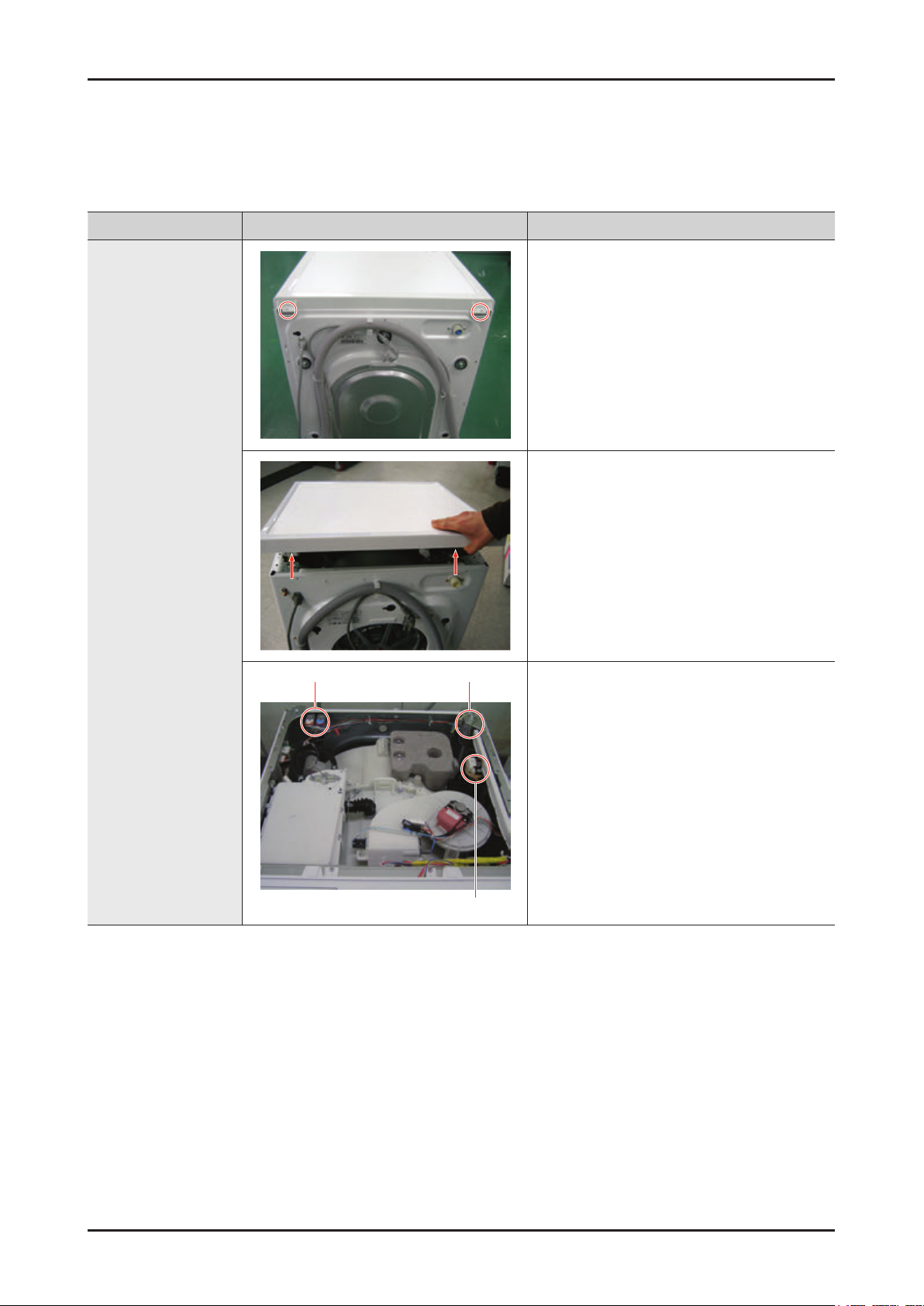
3-2. STANDARD DISASSEMBLY DRAWINGS
► This is a standard disassembly diagram and may differ from the actual product.
Use this material as a reference when disassembling and reassembling the product.
Part Figure Description
1. Remove the two screws holding the Top
Cover at the back of the unit.
2. Remove the top-cover by lifting it up after
pulling it back about 15mm.
ASSY COVER TOP
Water valve Noise filter
Sensor pressure
3. Then, the Water (Pressure) Sensor, Noise
Filter and Water Valve can be replaced.
Page 14
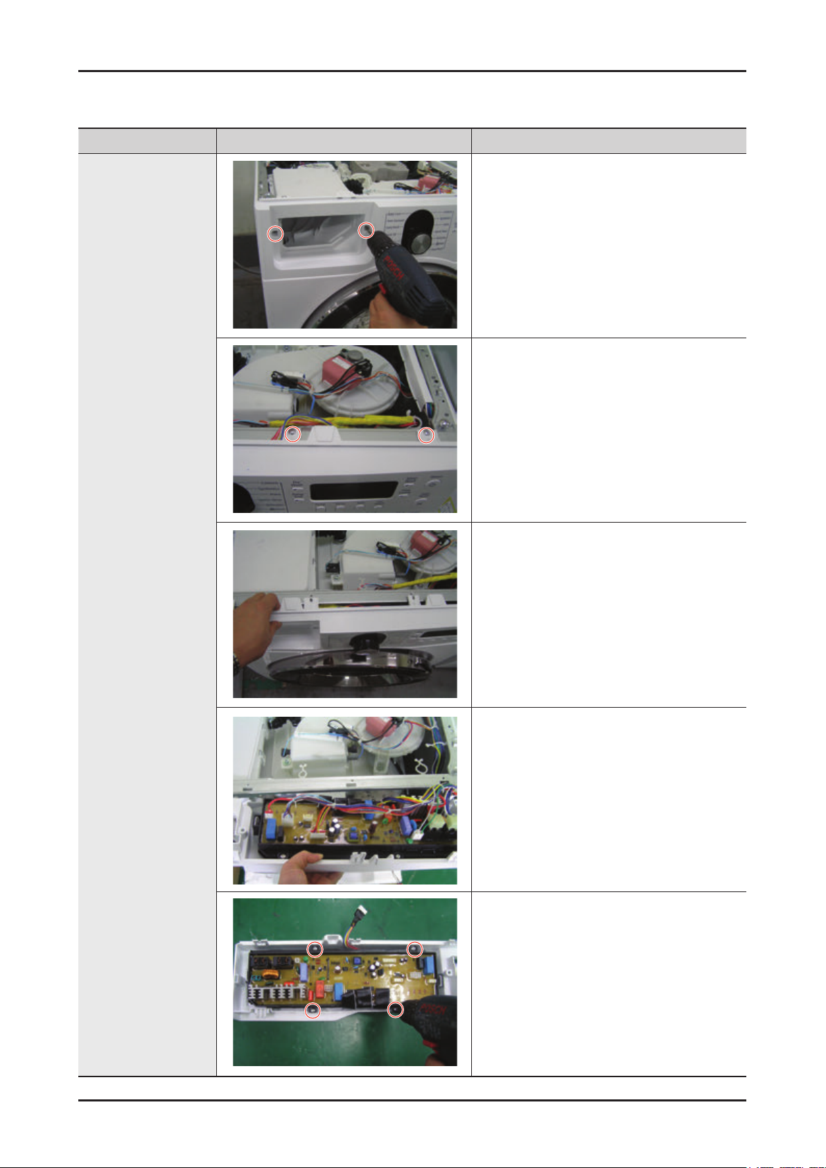
Part Figure Description
1. Remove the 2 screws holding the front
operating panel.
Remove the four screws at the top of the
2.
ASSY-PANEL
CONTROL.
MAIN-PCB AND
SUB-PCB PANEL
Hold the
3.
pulling it upwards and release the hook to
remove it.
4. Disconnect the terminals connected to the
PCB by hand.
5. Remove the four screws holding the PCB
and release the hooks on both sides to
remove the PCB for repair / replacement.
ASSY-PANEL CONTROL while
Removal and Reassembly _ 13
Page 15
14 _ Removal and Reassembly
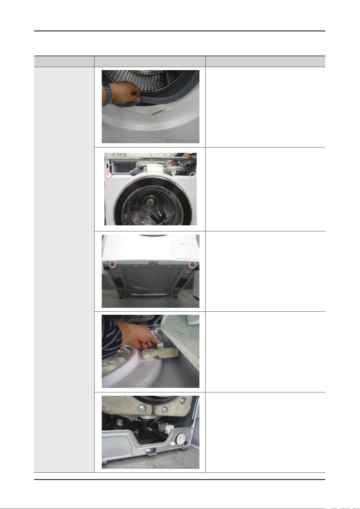
Part Figure Description
1. Separate the Wire-Diaphragm from the
Front-Frame and remove the Diaphragm.
2. Remove the two screws holding the
FRAME-FRONT
.
FRAME FRONT
3.
Remove the two screws holding the bottom
of the FRAME-FRONT
4.
Disconnect the terminal for the DOORLOCK switch.
The DOOR-DIAPHRAGM, HEATER, PUMP,
5.
SHOCK- DAMPER and DOOR LOCK
switch.
.
Page 16

Part Figure Description
COVER-BACK
BELT
• Remove the 4 screws holding the BackCover at the back of the washing machine.
1. Separate the belt and then assembly it.
2. Check if the belt position is at the center of
the Pulley.
Assembling the belt
Place the belt around the Motor-Pulley (
and then over the Pulley (
).
)
MOTOR
1. Separate the Wire Housing from the motor.
2. Remove the bolts holding the motor at the
back of the washing machine.
3.
Separate the motor.
When installing the Belt around the Motor
Pulley, the bottom of the belt must be
located on the second floor of the Motor
Pulley.
Removal and Reassembly _ 15
Page 17

16 _ Removal and Reassembly
Part Figure Description
1. Remove the three screws on the AIR WASH
fixed to the TUB.
AIR WASH
Terminals for
the Heater
Terminals for
the motor
2. Disconnect the terminals for the HEATER/
MOTOR/THERMISTOR.
Terminals for the thermistor
3. Remove the JOINT-DIAPHRAGM SCREW
assembled with the DIAPHRAGM.
Page 18

Part Figure Description
1. Remove the single HOUSING-AIR WASH
screw.
2. Release the six hooks by hand.
AIR WASH (Inside)
3. Remove the PTC-HEATER and
THERMISTOR for repair / replacement.
4. Remove the Nut.
5. Remove the two screws holding the
MOTOR for repair / replacement.
Removal and Reassembly _ 17
Page 19

18 _ Removal and Reassembly
Part Figure Description
1. Separate the Top Assy-Plate.
2. Separate the water supply valve wire.
WATER SUPPLY
VALVE
3. Remove the 2 screws holding the water
supply valve.
Page 20

Part Figure Description
Water valve Noise filter
1. Separate the Top Assy-Plate.
Sensor pressure
WATER LEVEL
SENSOR
2. Remove the screw holding the water level
.
sensor
DOOR-HINGE
3. Disconnect the wire between the
PRESSURE HOSE and the water level
sensor for repair / replacement.
1. Remove the 2 screws holding the Door
Hinge and separate the door.
2. Remove the 11 screws holding the Holder
Glass, separate the Holder Glass and
replace the hinge.
Removal and Reassembly _ 19
Page 21

20 _ Removal and Reassembly
Part Figure Description
1. Insert the (-) screwdriver into the upper part
of the Filter Cover and push it downwards
to release the catch.
2. Remove the remaining water through the
drainage hose.
Place a bowl under the drainage hose,
or the remaining water may flow out.
DRAIN PUMP
3. Separate the Drain Filter by turning it
counterclockwise.
Since the remaining water may flow
out, place a bowl underneath it when
separating the filter..
4. Remove the 1 screws holding the Drain
Pump.
2. Remove the remaining water through the
drainage hose.
Page 22

Part Figure Description
6. Release the BAND RING (2EA) to remove
the HOSE (2EA).
DRAIN PUMP
7. Push the
the PUMP
Disconnect the wires (2EA).
8.
Check Points for Troubleshooting
1.
Separate the Drain Filter and check if any alien substances are inside the pump (e.g.
coins, buttons .., etc.) → Remove these if found.
2. Check if the wire driving the pump is has come loose → Take the relevant countermeasure
if necessary.
When water leaks, check the assembly status of the Clamp Hose, and Cap Drain → Take
3.
the relevant countermeasure if necessary.
Turn the filter counterclockwise to remove the remaining water.
TUB inwards slightly to remove
.
Removal and Reassembly _ 21
Page 23

22 _ Removal and Reassembly
Part Figure Description
1. Open the Door.
Remove the Wire Diaphragm and remove it
from The Front Frame.
For easier disassembly, remove the
spring from the lower part of the
Diaphragm with a (-) screwdriver.
Since the Diaphragm can be damaged
when removing it, remove it slowly in
one direction.
DOOR-LOCK S/W
2. Remove the two screws.
3. Remove the screw holding the Door-Lock
S/W.
Remove the Door-Lock S/W.
Remove the connection wire.
(Remove the connector after releasing it by
pressing the catch.)
Page 24

Part Figure Description
1. Separate the Back Cover.
2. Separate the Connection Housing (3).
HEATER
3. Remove the nut holding the heater and
separate the Heater.
4. Remove the Heater from the Tub.
Caution
Make sure to insert
the Heater into the
correct position of
the bracket inside
the Tub when
reassembling it.
Otherwise, there is
a danger of a fire.
Make sure to push it inwards until the
packing part comes into the Tub completely
when reassembling it so that the packing
part is completely stuck to the
Fasten the holding nut with a force of 5Kgf/
cm2.
If the nut is not fastened properly, there is a
danger of water leaking.
Tub.
Reassembly is in the reverse order of the removal.
Removal and Reassembly _ 23
Page 25

24 _ Troubleshooting
4. TROUBLESHOOTING
4-1. ERROR MODES
► This is a washer integrated error mode. For detailed information, refer to the general repair scripts.
Drum
Error Type
Water Level
Sensor
Motor Driving
Error and Hall
Sensor Error
Water Supply
Error
Error
mode
1E
3E
3E1 3E1
3E2
3E3 3E3
3E4
4E
4E1 4Ed -
4E2 E8
Old
error
mode
1E
E7
3E
EA
EB
8E
3E2
3E4
4E
E1
For USA
LE 1E
3E
E3
bE
nF
-
Fully
automatic
3E
4E
Causes Remarks
-
The part of the hose where the water level sensor
is located is damaged (punctured).
- The hose is clogged with foreign material.
The hose is folded.
-
- Too much lubricant has been applied to the
insertion part of the air hose.
- Hose engagement error (disengaged)
-
Part fault (Faulty internal soldering)
- The water level sensor terminal is disengaged.
- Main PBA fault.
-
The PBA
- The motor spin net is not engaged.
- The motor’
circuited or cut)
- The hall sensor terminal is not connected.
- Foreign material (a screw) has entered the motor.
Motor overloaded due to too much laundry (Non-
sensing)
-
The motor hall sensor terminal is not connected.
- PBA fault
- The motor driving error from the PBA is weak.
: Unstable relay operation, etc.
- This occurs due to erroneous operating signals
for the motor hall sensor
- The IPM terminal of the main PBA is not
connected.
- The DD motor cover is out of place.
- The PCB housing terminal is not connected.
- PBA
- DD motor fault
-
Foreign material is entering the water supply
valve.
The water supply valve terminal is not connected.
(Wire disconnected)
- The warm water and rinse connectors are wrongly
connected to each other
- This occurs if the PCB terminal from the drain
hose to the detergent drawer is not connected.
Check whether the transparent hose is folded or
torn.
- The cold and warm water supply hoses are
wrongly engaged into each other.
The temperature of the water supplied through
the dry valve during a dry cycle is sensed as
higher than 70 ˚C.
- The water temperature is sensed as higher than
50 ˚C in the Wool or Lingerie courses.
connector terminal is not connected.
s internal coil is damaged (short-
.
fault
.
For USA
products, this
error occurs
because of
restrained
revolutions
For USA
products, this
error occurs
when an
interference is
generated due
to too much
laundry, etc.
If this error
occurs in the
W
The water
supplied for 1
minute drying
the
is 0.3 ~ 0.4 L.
ool course
drying cycle
Page 26

Drum
Error Type
Drain Error 5E
Motor Error 8E - 3E
Power Error
Communication
Error
Switch Error
(Main Relay
Error)
Error
mode
9E1
9E2 Plo
AE 13E - -
bE1 12E
bE2 14E
bE3 18E
Old
error
mode
5E
E5
PH1
For USA
nd 5E
2E
PF
E2 -
Sr -
Fully
automatic
Causes Remarks
-
The pump motor impeller is damaged internally.
- The wrong voltage (220 V → 110 V) is supplied to
the parts.
- Part fault
This occurs due to freezing in the winter season
-
- The drain hose is clogged. (Injection error, foreign
material)
- Clogged with foreign material
The water pump terminal is not connected: rubber
band, bills, cotton, hair pins, coins
-
This occurs when motor driving is unstable
because the motor hall sensor does not work.
- This occurs when the PBA
unstable or the control circuit has an error.
- Check whether the wire connector is connected
correctly or whether there is a contact error
Check the consumer’s power conditions.
: Make sure to check the operating voltage.
Connect a tester to the internal power
terminals during the Boil or Dry operations
and observe the washing machine’s operation
carefully
.
: Check the voltages. (An error occurs when
under or over voltage is supplied.)
: Check whether a plug receptacle is used.
-
When the connecting wire is 1m, a momentary
low voltage may drop up to 10 V
- Main PBA
-
This error is not a fault but occurs during a
momentary power failure
: If started again when this error code is
: If the washing machine is not operating and
- The signals between the sub and main PBAs are
not sensed because of a communications error.
Check the connector connections between
the sub and main PBAs carefully. → Check for
incorrect or loose connections, etc.
- Remove the sub PBA
faulty soldering.
- The Power button is pressed continually (for more
than 12 seconds).
- The switch is pressed unevenly because of a
deformation of the control panel.
- This error may occur when the screws that hold
the sub PBA in place are tightened too much.
- A button other than the Power button is
continually pressed (for more than 30 seconds).
-
Deformation of an internal plastic injection part
- A screw for assembling the sub PBA is tightened
too much.
-
The main relay of the PBA is short-circuited.
- The main relay terminal is connected incorrectly.
(The terminal is bent and contact cannot be
made.)
fault (sometimes)
displayed, the operation restarts from the cycle
that was stopped due to the power failure.
this error code is displayed, it is displayed to
notify that a power failure has occurred.
IPM operation is
C/Panel and check for any
.
For Full
Automated
products, no
error code is
displayed for a
power error
When the
PBA
relay does not
operate
.
motor
Troubleshooting _ 25
Page 27

26 _ Troubleshooting
Error Type
Cooling Error CE
Door Error
Fan Error FE
Error
mode
dE
door
dE1 dE1
dE2 dE2
Drum
Old
error
mode
CE
cE
dE
Ed
door
F
FE
For USA
- -
dS
(Before
operation)
dL
(During
operation)
LO
(Unlock
Fail)
FL
(Lock Fail)
- -
- -
Fully
automatic
dE
-
Causes Remarks
-
occurs when the temperature of the washing
This
machine is more than 55 ˚C and no draining is
performed.
n: If hot water comes into contact with skin, it
(Reaso
may cause burns.)
- This occurs when the water temperature, for a
specific course, exceeds 55 ˚C. In that case, the
water will be drained to the Reset level.
- This represents a thermal sensor error or any
misuse of the unit.
-
A switch contact error because of a deformation
of the door hook
- When the door is pulled by force
-
This occurs in the Boil wash because the door is
pushed due to a pressure difference from internal
temperature changes
- The door lock switch terminal is connected
incorrectly.
The door lock switch terminal is broken.
-
- This occurs intermittently because of an electric
wire leakage
-
Main PCB fault
- This occurs if the Power switch is turned on/off
continually and too much heat is generated (This
error is difficult to be reproduced.)
-
The start condenser terminal comes out of place
when inserting the top cover
- The fan motor has a wire disconnected or the belt
is out of place. Therefore, the fan does not start.
- The cooling wings are restrained or stains have
developed on the bearings.
does not start.
-
Start condenser fault
→ In this case, you cannot detect it with a tester.
Always replace the start condenser
.
Therefore, the fan
If this error
occurs for
another
reason, it
is due to a
washing heater
sensor fault.
Replace it.
When the door
is not opened
after the door
open operation
When the door
is not locked
after the door
close operation
Page 28

Error Type
Heater Error
W
ater Leakage
Error
Overflow Error
Error
mode
HE
HE1
HE2 HE2
HE3 -
LE
LE1
OE
OF
Old
error
mode
HE1
11E
Drum
HE
E5
E1
Ec
E9
OE
OF
E3
For USA
Hr
(Heater
Relay)
LE LE
OE -
Fully
automatic
-
Causes Remarks
-
The washing heater is short-circuited or has a
wire disconnected.
- The washing heater in the tub has an error.
(Contact error, temperature sensor fault)
- If the water level sensor operates without water
because water is frozen or for any other reason
and the temperature sensor engaged at the
bottom to prevent overheating for the washing
heater detects a temperature of 100 to 150 ˚C,
the washing machine turns the input power off.
- This error occurs when the red temperature
sensor at the center of the dry heater operates (at
a temperature higher than 145 ˚C)
: Corrective action – Press the button at the
center lightly
operate normally.
Alternatively
the temperature sensing is unstable because of
functional degradation.
- This occurs when the steam function does not
operate normally.
- This error does not occur in existing drum
products. Check whether the product is a steam
model
Heater engagement fault (out of place)
-
- The air hose is out of place and water leakage
occurs during the spin cycle.
- The tub back at the safety bolts fixing part is
broken.
- W
ater leakage occurs at the front with foaming
because of too much detergent
- Water leakage occurs because the connecting
hose to the detergent drawer is connected
incorrectly.
- The drain pump filter cover is engaged incorrectly.
- W
ater leakage occurs at the drain hose.
- The duct condensing holding screws are worn.
- The nozzle-diaphragm is engaged in the opposite
direction or the rubber packaging is omitted.
-
Water leakage occurs because the screws that
hold the tub back and front in place are fastened
incorrectly.
- The leakage sensor is faulty.
-
Water is supplied continually because the water
level detection does not work.
Because the drain hose is clogged and there
is an injection error (at a narrow section), the
water level detection does not work and water is
supplied continually.
- Water is supplied continually because of freezing
or because there is foreign material in the water
supply valve.
- This error may occur when the water level sensor
is degraded.
. The washing machine will
, replace the temperature sensor if
For USA
products, if
the heater
has no error,
this occurs
because of
a PBA relay
malfunction.
For USA
products, this
error occurs
because the
water level
sensor terminal
is out of place.
Troubleshooting _ 27
Page 29

28 _ Troubleshooting
Error Type
Temperature
Sensor Error
Unbalance
Error
Foaming
Detected
Mems PBA
Error Detected
Drum
Error
mode
tE1
tE2 tE2 - -
tE3 tE3 - -
UE
Sud -
Old
error
mode
tE1
- - E8
6E
UE
E4
For USA
tE -
dc UE
SUdS -
automatic
Fully
-
Causes Remarks
-
The washing heater in the tub has an error.
(Contact error, temperature sensor fault)
- The connector is connected incorrectly or is
disconnected.
- If the water level sensor operates without water
because the water is frozen or for any other
reason and the temperature sensor engaged at
the bottom to prevent overheating for the washing
heater detects a temperature of 100 to 150 ˚C,
the washing machine turns the input power of
- The temperature sensor for the duct assy fan
housing is faulty.
(A sensor fault such as an internal short-circuit or
wire disconnection)
- The connector is out of place or has a contact
error
.
- This occurs when the duct condensing
temperature sensor is open.
- This occurs when the duct condensing
temperature sensor has a wire disconnected or is
short-circuited.
- The connector is out of place or has a contact
error.
-
As laundry causes this error
- Find the reason for the unbalance and solve it as
directed in the user manual.
-
This occurs when too much foaming is detected.
It is also displayed while foaming is removed.
When the removal is finished, the normal cycle
proceeds. “Sud” or “SUdS” is displayed when too
much foaming is detected and “End” is displayed
when the removal of the foaming is finished.
(This is one of the normal operations. It is an error
for preventing non-sensing faults.)
- Error detected in the Mems PBA or data error
detected. Check the wire connections.
Replace if necessary.
1. Check the wire connections.
Replace the Mems PBA.
2.
3. Main PBA wire connection error or PBA
nano part malfunction. Replace if necessary.
, check the laundry.
f.
’s silver
Heater sensor
fault
: When the
connector is
connected
incorrectly or
has a wire
disconnected
or contact error
Duct
condensing
temperature
sensor
fault (for
models before
the silver nano
function was
applied)
Dry heater
temperature
sensor fault (for
models before
the silver nano
function was
applied)
Page 30

4-2. CORRECTIVE ACTIONS FOR EACH ERROR CODE
sensor and the connector
are connected.
KHz with no load
Check the water level sensor
frequency.
- Check it after the water level
- Frequency: Approx. 26.4
► DD MOTOR
Check the resistance on the
main PCB motor. (Between pins
1 and 3, and 1 and 4 of the four
MΩ
(4) pins)
- Resistance: Approx. 2 to 4
- Check the voltage when the
power is on.
► UNIVERSAL MOTOR
Check the Resistance of Nos.1
and 4 of the wire pin on the side
of the TACHO SENSOR.
40 to 45 Ω (Normal)
- Resistance: Approximately
needs to be reproduced.
(Turn the drum by hand.)
to 12V (Voltages may differ
depending on the speed of
the revolutions.)
► THREE PHASE MOTOR
Measure the Resistance of Nos.
2 and 3 of the wire pin on the
side of the HALL SENSOR.
- The revolution of the drum
- Resistance: Approximately 3
Check the water level sensor terminal
connections and contacts.
An error occurs if an incorrect water level
sensor is used. Make sure to check the
material code. (Abnormal operation)
If the error persists despite taking the action
above, replace the PBA.
•
•
• If the water level sensor is faulty, replace it.
•
level sensor terminal
sensor is folded.
• Water level sensor fault
• Incorrect connections of the water
• The hose part for the water level
• Main PCB fault
1E
control circuit is faulty, replace the
Check whether the stator of the motor cover is
damaged.
material.
connections and contacts.
due to too much laundry.
hall sensor.
• Check the motor connector terminal
• 3E1 is displayed because overloading occurs
• If the hall sensor terminal is faulty, replace the
Washing motor fault
•
washing motor/hall sensor
• Washing motor hall sensor fault
• Incorrect connections of the
3E
3E1
• Check for coil disconnections due to foreign
•
ashing motor rotor and stator
fault
connector
W
•
3E2
3E3
3E4
PBA.
• If the PBA
• Main PCB fault
Error Type Error Mode Causes Corrective Actions Description of Photo
Water Level
► These are common troubleshooting procedures for each drum-type washer error mode. For detailed information, refer to the general repair scripts.
Sensor
Washing Motor
Error and Hall
Sensor Error
Troubleshooting _ 29
Page 31

30 _ Troubleshooting
water supply valve.
between the terminals of the
water supply valve.
foreign material in the water
supply valve diaphragm.
1. Check the resistance for the
- Resistance: 4.0 to 5.0 Ω
2. Check whether there is
6.3 Ω between the Terminals
for the Water Supply Valve
► DRAIN MOTOR
Resistance: Approximately
174 Ω between the Terminals
for the Water Supply Valve
► DRAIN PUMP
Resistance: Approximately
-
s communication circuit is
disconnected, replace it.
• If the water supply valve has a wire
Error Type Error Mode Causes Corrective Actions Description of Photo
Check whether the water supply valve is
clogged with foreign material and whether
water is supplied continually.
of freezing in the winter season.
the PBA.
•
• Check whether no water is supplied because
• If the PBA relay operates abnormally, replace
• Water supply value fault
• Main PCB fault
• Freezing in the winter season
4E
4E1
4E2
Water Supply
Error
If the drain pump operates abnormally
intermittently when the temperature of the
water in the tub is high.
to freezing in the winter season, check the
method to remove the freezing and remove as
pump motor are restrained by foreign material.
process.
and if there is any wires disconnected.
• Check whether the revolutions of the drain
• Check the same thing for the natural drain
• Check whether the connections are correct
•
pump• Main PCB fault
• Drain pump fault
• Freezing in the winter season
• Foreign materials in the drain
Drain Error 5E
directed.
• If the motor revolutions are restrained due
contacts between the sub and main PBAs.
• Check the wire connections and terminal
• Check whether the sub PBA is short-circuited
• Check for disconnected wires.
main PBAs are not sensed.
• The signals between the sub and
AE
Communication
faulty, replace it.
because of moisture.
• If the main PBA’
between the sub and main PBAs.
• Incorrect wire connections
Error
Page 32

occurs after approx. 30
seconds has passed.
between a control panel
Check the contact between the
control panel buttons and their
corresponding tact switch.
- There must be a gap
Otherwise, an error
button and its corresponding
micro switch.
f error has
GAP
terminals and the voltage
of the Heater.
Check 27±10% on both
Check the resistance on the
Heater. (For faulty features)
Check the voltages on the red
/ blue terminals of the Heater
while washing.
.
tact switch is continually pressed.
• Check whether either the Power switch or a
Error Type Error Mode Causes Corrective Actions Description of Photo
screws are fastened too much. If they are
fastened too much, loosen them a little.
occurred, replace the main PBA.
connections are incorrect. Check the
connections. If there is no error in the
connections, replace the main PBA.
• Check whether the service PBA holding
• If the main PBA switching IC on/of
• The “bE3” error occurs if the main relay
button other than the Power
The Power button is continually
pressed.
button is continually pressed.
•
• A
• Main PCB relay fault
bE1
bE2
bE3
Switch Error
(Main Relay
Error)
This error occurs if the water temperature
•
is due to a temperature sensor fault. Replace
is more than 50 ˚C in draining. Check the
temperature.
• If the water temperature is normal, this error
• Washing temperature sensor fault
• Description of PL hazard
Cooling Error CE
to prevent water leakage.
the washing heater
When replacing the washing heater, take care
prevention
Troubleshooting _ 31
Page 33

32 _ Troubleshooting
► TYPE 1
Check the door switch voltage.
Check the voltage after the
power is on. (That is, check the
door switch when the power
button is turned on and no
operating key is pressed.)
.
during the Boil cycle.
If it is detected that the door is open, close the
door
Check and repair the power wire connections
• If a dE error occurs, check whether it occurs
-
• The 220V is directly connected to the door.
► TYPE 2
The resistance of Nos. 3 and 5
of the DOOR LOCK SWITCH
must be approximately 949 Ω.
.
and insulation state.
Replace if faulty.
• Check the main PBA door sensing circuit.
• Check the door switch. Replace if faulty
► TYPE 1
Check the dry fan motor
operation.
Check the motor voltage during
the dry cycle.
,
defects for the dry motor.
faults.• If the start condenser has a functional error
• Check for disconnected wires and insulation
• Check connector connections and contact
► TYPE 2
the motor rotates normally. However, because
the start condenser operates unstably, replace
it.
The resistance of both terminals
of the AIR WASH MOTOR must
be approximately 298 Ω.
Error Type Error Mode Causes Corrective Actions Description of Photo
• Door switch fault
• Drain pump fault
• Dry duct fan motor fault.
• Main PCB fault
dE
dE1
dE2
Door Error
• Main PCB fault
• Dry duct fan motor fault
FE
Dry Duct Fan
Error
Page 34

hose is folded, cut, or
material, such as
underwear wires or coins.
(Automatic Drainage)
-
► DRAIN PUMP TYPE
Check for any foreign
Check whether there is any
foreign material in the bellows.
ub connections and take any
► PUMP TYPE
Check for any leakage on the
base, Hose, Valve and Tub
connections.
Check the hose connected to
the water level sensor.
damaged.
Check whether the
An HE or HE1 error occurs.
overheating sensor is faulty, replace it.
- An HE2 error occurs.
Check for disconnected wires for the washing
heater. Replace if faulty.
-
•
• Because the dry heater or air refresh heater
Heater fault
sensor at the center of the dry
heater
•
• A fault of the red temperature
HE
HE1
HE2
- An HE3 error occurs.
• Check the steam heater. Replace if faulty.
• Steam function fault
• Freezing in the winter season
HE3
Error Type Error Mode Causes Corrective Actions Description of Photo
Heater Error
the drain bellows are clogged with foreign
material. Remove the foreign material.
Check the drain motor operation. Replace if it
Check for any leakage on the base, Hose,
Valve and T
required action.
•
• For natural draining, this error occurs because
Check for any leakage.
•
• Foreign material in the DV case
LE
ater Leakage
W
Error
does not operate normally.
•
engagement in the product
• Fault of a hose or incorrect part
LE1
Check the hose. This error occurs if it is torn
or has a hole.
winter season. Check the method to remove
replace it.
• If the water level sensor has a functional error,
•
Water level sensor fault
•
OE
Overflow Error
freezing and follow as directed.
• This error occurs if water is frozen in the
• Freezing in the winter season
OF
Troubleshooting _ 33
Page 35

-
, replace it.
- A tE1 error occurs.
temperature sensor connector.
functional error, replace it.
- A tE2 error occurs.
condensing temperature sensor connector.
has a functional error, replace it.
temperature sensor connector.
a functional error
• Check the connections for the dry heater
• Check the connections for the washing heater
• If the washing heater temperature sensor has
• If the dry heater temperature sensor has a
• Check the connections for the duct
- A tE3 error occurs.
• If the duct condensing temperature sensor
-
,
make sure to check and follow the related
directions in the user manual and follow
the directions.
they may cause an unbalanced situat ion.
- If they are small but absorb a lot of water
• Check the type of laundry. Check whether
• Washing temperature sensor fault
• Dry temperature sensor fault
tE1
Error Type Error Mode Causes Corrective Actions Description of Photo
34 _ Troubleshooting
of the dry condensing sensor
Freezing in the winter season
• Faulty and incorrect connections
• Main PCB fault
•
tE2
tE3
Temperature
Sensor Error
Motor hall sensor fault
•
• Caused by the laundry
Unbalance Error UE
Page 36

. PCB DIAGRAM
-1. MAIN PCB (BEST: WF880*P* / WF870*P*)
Location Part No. Function Description
1 RY1 Main Relay Receives 220 ACV to operate the PBA.
2 RY3 Heater Relay For driving the heater power
3 CN9 Power Supply T
4 CN8 Water Level and Thermal Sensor Connection T
5 CN5 Motor Protector Connection Terminal Protects the motor against abnormal current.
6 CN4 Silver-Nano Control Connection
7 CN6 Terminal for Each Driving Section Locks the door, supplies cold/hot water
8 CN3 Motor Tacho Connection T
9 CN2 Motor Power Supply T
_ PCB Diagram
erminal Receives 220 ACV to operate the PBA.
erminal Detects the water supply / drainage and the heater operations.
Terminal Controls the behavior of the silver-nano control PBA.
, and operates the drain motor
erminal Controls the speed of the motor with the tachometer.
erminal Detects whether the motor is operating normally.
Page 37

-2. MAIN PCB (BETTER: WF880*S* / WF870*S*)
Location Part No. Function Description
1 RY1 Main Relay Receives 220 ACV to operate the PBA.
2 RY3 Heater Relay For driving the heater power
3 CN9 Power Supply T
4 CN8 Water Level and Thermal Sensor Connection T
5 CN5 Motor Protector Connection Terminal Protects the motor against abnormal current.
6 CN4 Silver-Nano Control Connection
7 CN6 Terminal for Each Driving Section Locks the door, supplies cold/hot water
8 CN3 Motor Tacho Connection T
9 CN2 Motor Power Supply T
erminal Receives 220 ACV to operate the PBA.
erminal Detects the water supply / drainage and the heater operations.
Terminal Controls the behavior of the silver-nano control PBA.
, and operates the drain motor
erminal Controls the speed of the motor with the tachometer.
erminal Detects whether the motor is operating normally.
PCB Diagram _ 6
Page 38

-3. CIRCUIT DIAGRAMS OF MAIN PARTS (BEST: WF880*P* / WF870*P*)
► CN4
► CN3
1. Motor Tachometer Connection
2. NC
3. NC
4. Motor Tachometer Connection
1. Silver-Nano Forward Current Control
2. Silver-Nano Backward Current Control
3. Silver-Nano Current Volume Control
4. Silver-Nano Activation On/Off
5. GND
► CN2
1. Motor-Driving Relay Connection
2. NC
3. Motor-Driving Power Connection
4. High Speed Relay Connection
5. High Speed Relay Connection
6. Motor-Driving Relay Connection
► CN5
1. Motor Protector Connection
2. Motor Protector Connection
_ PCB Diagram
► CN6
1. Air Wash FAN Connection
2. NC
3. Air Wash Heater Connection
4. Door Lock Relay Connection
5. Drain Pump Connection
6. Hot-Water Valve Connection
7. Spare Valve Connection
8. Cold-Water Valve Connection
► CN8
1. Heater Temperature Sensor
2. Heater Temperature Sensor
3. Water-Level Sensor Signal
4. 5V
5. GND
6. NC
7. Leakage Sensor
8. NC
► CN9
Power Supply
► Relay
RY1 Power Supply Relay
RY3 Heater Relay
Page 39

-4. CIRCUIT DIAGRAMS OF MAIN PARTS (BETTER: WF880*S* / WF870*S*)
► CN4
► CN3
1. Motor Tachometer Connection
2. NC
3. NC
4. Motor Tachometer Connection
1. Silver-Nano Forward Current Control
2. Silver-Nano Backward Current Control
3. Silver-Nano Current Volume Control
4. Silver-Nano Activation On/Off
5. GND
► CN2
1. Motor-Driving Relay Connection
2. NC
3. Motor-Driving Power Connection
4. High Speed Relay Connection
5. High Speed Relay Connection
6. Motor-Driving Relay Connection
► CN5
1. Motor Protector Connection
2. Motor Protector Connection
► CN6
1. Air Wash FAN Connection
2. NC
3. Air Wash Heater Connection
4. Door Lock Relay Connection
5. Drain Pump Connection
6. Hot-Water Valve Connection
7. Spare Valve Connection
8. Cold-Water Valve Connection
► CN8
1. Heater Temperature Sensor
2. Heater Temperature Sensor
3. Water-Level Sensor Signal
4. 5V
5. GND
6. NC
7. Leakage Sensor
8. NC
► CN9
Power Supply
► Relay
RY1 Power Supply Relay
RY3 Heater Relay
PCB Diagram _
Page 40

-5. SUB PCB (BEST: WF880*P* / WF870*P*)
Location Part No. Function Description
1 BUZZER1 BUZZER Circuitry Emits a sound when a menu key or encoder key is pressed or when a program is finished.
2 DSP1 Time Display Displays the remaining time of the selected cycle.
3 CN1 Program Writing Connected when writing a program for updating or modifying the software.
4 DSP2 Cycle Display Displays menus and the progress.
_ PCB Diagram
Page 41

-6. SUB PCB (BETTER: WF880*S* / WF870*S*)
Location Part No. Function Description
1 BUZZER1 BUZZER Circuitry Emits a sound when a menu key or encoder key is pressed or when a program is finished.
2 DSP1 Time Display Displays the remaining time of the selected cycle.
3 CN1 Program Writing Connected when writing a program for updating or modifying the software.
PCB Diagram _
Page 42

-7. DETAILED DESCRIPTIONS OF CONTACT TERMINALS (SUB PCB-BEST: WF880*P* / WF870*P*)
_ PCB Diagram
► CN1
1. Program Writing ISP_TEST Connection
2. GND
3. 5V
4. Program Writing RESET Connection
5 Program Writing TX Connection
6. Program Writing RX Connection
Page 43

-8. DETAILED DESCRIPTIONS OF CONTACT TERMINALS (SUB PCB-BETTER: WF880*S* / WF870*S*)
► CN1
1. Program Writing ISP_TEST Connection
2. GND
3. 5V
4. Program Writing RESET Connection
5 Program Writing TX Connection
6. Program Writing RX Connection
PCB Diagram _
Page 44

. WIRING DIAGRAM
-1. WIRING DIAGRAM
REFERENCE INFORMATION
BLK BLACK
BLU BLUE
GRN GREEN
GRY GRAY
NTR NATURAL
ORG ORANGE
PNK PINK
RED RED
SKYBLU SKYBLUE
VIO VIOLET
WHT WHITE
YEL YELLOW
4 _ Wiring Diagram
Page 45

. SCHEMATIC DIAGRAM
JUMP
AC1
AC2
(AC1)
(AC1)
GND_POWER
RY3(AC1)
7
1
SENSOR
8
ROTOR
LEAKAGE
NOISE
STATOR
AC100-120V
AC220-240V
DOOR SWITCH
6
STATOR
EEPROM
RESET
4
5
PROTECTOR
AG PCB
WATER
PRE VALVE
5V
W/L SENSOR
SCHEMATIC DIAGRAM
GND
L
N
HOT VALVE
COLD VALVE
FAN
THERMAL
CUT OFF
LEVEL
AIRWASH HEATER
FILTER
WASHING MOTOR
TACHO
AC DETECT
THERMISTOR
THERMISTOR
2
POWER_RELAY
HEATER_RELAY
RY1(AC2)
3
D-PUMP
2
i6
1
i7
8
GND
9
VCC
DGND
+12V
13
O4
12
O3
11
O2
10
O1
6
i2
5
i3
4
i4
3
i5
KID65003AP
IC8
7
i1
16
O7
15
O6
14
O5
SMW250-06DW,WHT
1
2
3
4
5
6
R83
2.7Kohm,J,0.5W
CN1
TR7
KRC246S,0.2W
I
1
G
2
3
O
C23
50V,1nF
+12V
C10
25V,10nF
123
DGND
CM1
630V,100nF
DGND
DGND
X1
CSTLS16M0X51,16MHz
2
3
4
CM2
250V,10nF
DGND
BD1
1
50V,100nF
C33
DGND
50V,100nF
CE10
35V,10uF
R65
10Kohm,J,0.125W
C18
DGND
DGND
CE3
50V,1uF
C19
50V,100nF
CE5
25V,470uF
R49
620ohm,J,1W
1KV,2.2nF
DGND
DGND
D21
BAV99
132
C21
1
ZNR1
460V
DE39-60001A
OJ1
CN9
YDW236-01,WHT
ACS108-5Sx
TRIAC4
1
OUT
2
COM13G
4
COM2
R38
10Kohm,J,0.125W
PC1
LTV817B
1
2
IN
1
GND
2
OUT
3
R59
10Kohm,J,0.125W
1
2
4
3
+12V
IC10
NJM7805
DGND
LTV817B
PC4
R19
10Kohm,J,0.125W
C29
50V,100nF
DGND
D30
UG2D
R75
100Kohm,J,2W
COM13G
4
COM2
D26
TRIAC3
ACS108-5Sx
1
OUT
2
DGND
CC1
275V,680nF
1KV,2.2nF
D28
4
GND
5
INB+
6
INB-
7
OUTB
8
VCC
AGND
C27
DGND
IC9
KA2904
1
OUTA
2
INA-
3
INA+
BP1S2S3EN_UV
4
D
5NC6S7S8
IC11
R46
620ohm,J,1W
R39
10Kohm,J,0.125W
R47
620ohm,J,1W
C26
25V,10nF
2
1 4
3
+12V
+5V
C22
50V,100nF
RY2
AJW2211
C15
50V,10nF
R69
1Kohm,J,0.125W
R18
10Kohm,J,0.125W
+5V
CE6
500V,10uF
R68
100Kohm,J,2W
R60
1Kohm,J,0.125W
2
E
C
3
DGND
+5V
R72
4.7Kohm,J,0.25W
50V,100nF
C28
TR5
MMBT3904,0.35W
1
B
T1T2
G
+12V
+5V
TRIAC5
12A
1
2 3
4
+12V
DGND DGND
R79
1Kohm,J,0.125W
PCF-112D2M-B
RY3
VAR1
460V
DGND
DGND
R45 220ohm,J,0.25W
R78
20Kohm,J,0.25W
1
B
2
E
C
3
D32
UF4007
4
3
DGND
DGND
TR4
MMBT3904,0.35W
RELAY3
PCJ-112D3MH
2
1
R58
620ohm,J,1W
C14
50V,100nF
+8V
C30
50V,10nF
R84
2.4Kohm,J,0.5W
R56
47Kohm,J,0.125W
R54
1Kohm,J,0.125W
27,1.5A
DGND
DGND
DGND
C11
50V,100nF
PTC1
9
P80
IC1
7042P
IN
1
GND
2
OUT
3
74
P6175P6276P6377P6478P6579P66
8
P75
80
P67
67
P5268P5369P54
7
P74
70
P5571P5672P5773P60
6
P73
60
P32
61
P33
62
PB0
63
PB1
64
PB2
65
P5066P51
52
P12
53
P13
54
P14
55
P15
56
P16
57
P17
58
P30
59
P31
45
P04
46
P05
47
P06
48
P07
49
DVSS
5
P72
50
P10
51
P11
38
P4239P43
4
P71
40
HV-Monitor
41
P00
42
P01
43
P02
44
P03
30
P9631P9732PA033PA134PA235PA336P4037P41
23
X2
24
DVSS
25X126
AM127RESET28P9429P95
3
P70
16
P87
17
P90
18
P91
19
P92
2
AVCC
20
P93
21
AM0
22
DVCC
1
AVSS
10
P81
11
P82
12
P83
13
P84
14
P85
15
P86
MICOM1
TMP91FU62FG
R43 220ohm,J,0.25W
R42
220ohm,J,0.25W
1000uH,ADR3102J
+12V
TR6
RN2427,0.2W
1
I
2
G
O
3
L1
DGND
R82
10Kohm,J,0.125W
AGND
123 4
5678
DGND
YDH236-01S,BLK
1
RTE24012
RELAY2
R48
620ohm,J,1W
DGND
CN7
730uH,NV2-08730
R67
100ohm,J,0.5W
COIL1
4
5
R74
100Kohm,J,0.5W
+12V
+12V
CN4
SMW250-05DW,WHT
1
2
3
LTV814
124
3
+5V
DGND
C8
50V,100nF
PC3
CE4
35V,10uF
+5V
AGND
D29
E2
4
VSS
5
SDA
6
SCL
7
NWC
8
VCC
C2
50V,100nF
24C04
IC2
1
E0
2
E1
3
6
7
8
9
R77
4.7Kohm,J,0.25W
14
15
16
17
18
192
20
3
4
5
F2
*
1
10 11
12
13
R76
100Kohm,J,2W
+5V
1
2 3
4
+5V
+12V
+12V
2
COM13G
4
COM2
+5V
DGND
RY1
PCF-112D2M-B
COM
1
OUT
2G3
TRIAC2
ACS108-5Sx
1
OUT
C13
50V,10nF
TRIAC1
ACS120-7Sx
50V,100nF
4
5
+5V
DGND
C24
RELAY1
OMIH-SS-112D
1
2
3
DGND
1N4007
D34
CE8
35V,10uF
R52
10Kohm,J,0.125W
+5V
D31
R40
27Kohm,J,0.25W
6
7
8
DGND
DGND
D24
1N4148
CN8
SMW250-08DW,WHT
1
2
3
4
5
3
DGND
C20
50V,100nF
ACS120-7Sx
TRIAC6
COM
1
OUT
2
G
D33 1N4007
+5V
+5V
DGND
R63
6.8Kohm,F,0.25W
R64
20Kohm,J,0.25W
10Kohm,J,0.125W
AGND
C1
50V,100nF
R81
100ohm,J,2W
R70
200Kohm,J,0.125W
4
R53
300ohm,J,2W
R50
8
CN3
SMW250-04DW,WHT
1
2
3
CN6
SMW420A-08,_
1
3
2
4 5
6
7
R73
1Kohm,J,0.125W
CE9
25V,470uF
DGND
10Kohm,J,0.125W
C32
50V,100nF
2
3 4
5
6
+5V
R80
CN2
SMW420-06,_
1
3
4 5
6
7
8
C25
50V,10nF
LVT1
EE1616-H
1
2
DGND
R51
1Kohm,J,0.25W
132
CE11
35V,10uF
R71
270kohm,F,1W
BAV99
D22
2
20
3
4
5
6
7
8
9
10 11
12
13
14
15
16
17
18
19
+12V
F1
*
1
3
i5
2
i6
1
i7
8
GND
9
VCC
DGND
DGND
14
O5
13
O4
12
O3
11
O2
10
O1
6
i2
5
i3
4
i4
IC7
KID65003AP
7
i1
16
O7
15
O6
R61
1Kohm,J,0.25W
DGND
+5V
R44 220ohm,J,0.25W
DGND
R66
100ohm,J,0.5W
R55
1Kohm,J,0.25W
C12
50V,100nF
DGND
C16
50V,10nF
CE1
50V,1uF
D27
C5
50V,100nF
+12V
+5V
DGND
19
2
20
3
4
5
6
7
8
9
1
10
11
12
13
14
15
16
17
18
F3
*
YDW236-02,GRN
1
2
R85
9.1Kohm,F,0.25W
CE7
25V,1000uF
CN5
D25
1N4148
D23
P6KE6.8A
10Kohm,J,0.125W
R62
270kohm,F,1W
25V,10nF
R12
+5V
+5V
DGND
DGND
C31
4.7Kohm,J,0.25W
C9
50V,100nF
A
2
C
3
+12V
+8V
R41
243
TL431
IC12
R1
LTV814
PC2
1
C17
50V,100nF
R57
180ohm,J,2W
MTZJ5.6B
ZD1
+5V
+12V
R2
10Kohm,J,0.125W
DGND
HEATER_RELAY
DOOR_LOCK
AC_DETECT_1
LED_DATA1
AC1
AC1
AC
DGND
VCC
VCC
GND
AIRWASH_HEATER
LED_DATA0
WATER_THERMISTER_1
TRIAC_THERMISTER_1
AIRWASH_THERMISTER_1
MOTOR_CWCCW
MOTOR_HSPEED
MAIN_RELAY
COLD_TRIAC
PRE_TRIAC
HOT_TRIAC
PUMP_TRIAC
VCC
BUZZER_ENVELOPE
BUZZER_FREQ
LEAKAGE_1
AG_B_1
AG_A_1
AG_IH_1
TX
JOG_DIAL_B
JOG_DIAL_A
AIRWASH_FAN
AG_PWM_1
MOTOR_PHASE
TACHO_1
ZEROCROSS_1
GND
DIGIT_4
DIGIT_3
DIGIT_2
DIGIT_1
DIGIT_0
LED_DATA9
LED_DATA8
LED_DATA7
LED_DATA6
LED_DATA5
LED_DATA4
LED_DATA3
LED_DATA2
STDBY_1
DOORLOCKSTATE_1
GND
RX
WATER_FREQ_1
OPTION_SCAN
KEY_SCAN
GND
SCL
SDA
DIGIT_12
DIGIT_11
DIGIT_10
DIGIT_9
DIGIT_8
DIGIT_7
DIGIT_6
DIGIT_5
GND
ZEROCROSS RX
TX
STDBY
ISP_TEST
RESET
WATER_FREQ
AC2
GND
STDBY_1
AC1
AC
AC
AG_IH
AG_A
TACHO
MOTOR_PHASE
AG_IH_1
AG_A_1
AC_DETECT
DOORLOCKSTATE
AG_B
AC2
DOORLOCKSTATE
AG_IH
AG_PWM
AIRWASH_HEATER
AG_PWM_1
DOORLOCKSTATE_1
AG_B_1
TACHO_1
WATER_FREQ_1
AG_PWM
AC_DETECT
TRIAC_THERMISTER
WATER_THERMISTER
AIRWASH_THERMISTER
HEATER_RELAY
AIRWASH_THERMISTER_1
WATER_THERMISTER_1
TRIAC_THERMISTER_1
AC_DETECT_1
ZEROCROSS_1ZEROCROSS
AIRWASH_FAN
PUMP_TRIAC
DOOR_LOCK
MOTOR_HSPEED
MOTOR_CWCCW
PRE_TRIAC
COLD_TRIAC
HOT_TRIAC
AC1 AC1
WATER_FREQ
LEAKAGE_1
LEAKAGE
ISP_TEST
RESETRESET
AC1
WATER_THERMISTER
AIRWASH_THERMISTER
LEAKAGE
AG_A
AG_B
VCC
MAIN_RELAY
STDBY
TACHO
SDA
SCL
VCC
TRIAC_THERMISTER
-1. MAIN CONTROL (BEST: WF880*P* / WF870*P*)
► This Document can not be used without Samsungs authorization.
Schematic Diagram _
Page 46

-2. MAIN CONTROL (BETTER: WF880*S* / WF870*S*)
JUMP
HOT VALVE
6
GND_POWER
HEATER_RELAY
6
AC100-120V
5
ROTOR
4
WASHING MOTOR
5
THERMAL
NOISE
PROTECTOR
RY1(AC2)
FAN
L
N
STATOR
3
CUT OFF
4
2
RY3(AC1)
LEVEL
SENSOR
8
7
FILTER
LEAKAGE
POWER_RELAY
1
5V
STANDBY
2
PRE VALVE
STATOR
D-PUMP
EEPROM
COLD VALVE
AG PCB
DOOR SWITCH
AIRWASH HEATER
AC220-240V
THERMISTOR
SCHEMATIC DIAGRAM
TACHO
WATER
W/L SENSOR
THERMISTOR
RESET
LEAKAGE
1
GND
3
2
P67
11
P80
75
P60
76
P6177P62
78
P63
79
P6480P65
1
P66
10
P75
68
P51
69
P52
70
P5371P54
9
P74
72
P5573P5674P57
61
P31
8
P73
62
P32
63
P33
64
PB0
65
PB166PB2
67
P50
53
P11
54
P12
55
P13
56
P14
57
P15
58
P16
59
P17
60
P30
46
P03
47
P04
48
P05
49
P06
50
P07
51
DVSS
7
P72
52
P10
39
P4140P42
41
P43
6
P71
42
EMU0
43
P00
44
P01
45
P02
5
P70
32
P9633P9734PA0
35
PA136PA237PA338P40
24
DVCC
25X226
DVSS27X128AM129nRESET30P94
31
P95
17
P86
18
P87
19
P90
20
P91
21
P92
4
AVCC
22
P93
23
AM0
3
AVSS
12
P81
13
P82
14
P83
15
P84
16
P85
ACS120-7Sx
COM
1
OUT2G
3
TMP91FU62DFG
MICOM1
27,1.5A
PTC1
TRIAC6
DGND
R58
620,J,1W
1KV,2.2nF
C21
5
6
D34
1N4007
3
2
SMW250-06DW,WHT
CN1
1
2
3
4
+12V
D22
BAV99
1
220,J,0.25WR42
1
i7
8
GND9VCC
220,J,0.25WR43
12
O3
11
O2
10
O1
6
i2
5
i3
4
i4
3
i5
2
i6
IC7
7
i1
16
O7
15
O6
14
O5
13
O4
50V,100nF
C20
KID65003AP
BD1
1
2
3
4
DGND
123
DGND
DGND
+5V
X1
CSTLS16M0X51,16MHz
D28
DGND
DGND
C10
25V,10nF
MMBT3904,0.35W
TR5
B
1
E
2
3
C
R71
270K,F,1W
DGND
4.7K,J,0.25W
R72
BP1S2S3EN_UV
4
D
5
6
NC
S7S
8
IC11
3
4 5
6
7
8
C28
50V,100nF
EE1616-H
LVT1
1
2
DGND
C17
50V,100nF
7042P
IC1
IN
1
GND
2
OUT
3
DGND
+5V
C24
50V,100nF
1K,J,0.25WR55
DGND
DGND
R61
1K,J,0.25W
9.1K,F,0.25W
R85
1
23
4
10K,J,0.125W
R1
C19
50V,100nF
RY3
PCF-112D2M-B
1N4148
D24
DGND
D26
220,J,0.25WR44
+12V
ACS108-5Sx
TRIAC3
1
OUT2COM13G
4
COM2
1
2
3
4 5
6
7
8
1
23
4
CN6
SMW420A-08,_
T1T2
G
+5V
PCF-112D2M-B
RY1
D27
TRIAC5
12A
50V,10nF
C16
+5V
DGND
CN7
YDH236-01S,BLK
1
R47
620,J,1W
1
OUT2COM13G
4
COM2
CE4
35V,10uF
C31
25V,10nF
DGND
ACS108-5Sx
TRIAC2
1K,J,0.125W
DGND
+12V
2.7K,J,0.5W
R83
R60
UF4007
D32
P6KE6.8A
D23
124
3
2
1 4
3
PC2
PS2565
3
5
DGND
OMI-SH-112LM
RY2
PCJ-112D3MH
RELAY3
2
1 4
C33
50V,100nF
2
4
3
R81
10K,J,0.125W
2
PC4
PS2561
1
DGND
PS2561
PC1
1
1 2 3 4
5678
620,J,1W
+5V
RELAY2
RTE24012
10K,J,0.125W
R38
DGND
R48
DGND
+5V
DGND
R69
DGND
50V,100nF
C11
1K,F,0.25W
50V,100nF
C5
VAR1
460V
R39
10K,J,0.125W
1K,F,0.25W
R73
3
C
100,J,0.5W
R66
MMBT3904,0.35W
TR4
B
1
E
2
275V,680nF
CC1
TRIAC1
COM
1
OUT2G
3
R63
6.8K,F,0.25W
1
2
3 4
5
6
+8V
ACS120-7Sx
1
OUT2COM13G
4
COM2
CN2
SMW420-06,_
AGND
DGND
+12V
+12V
TRIAC4
ACS108-5Sx
+12V
4.7K,J,0.25W
R77
+12V
DGND
CE8
35V,10uF
2
3
O
10K,J,0.125W
R19
KRC246S,0.2W
TR7
I
1
G
CE7
25V,1000uF
+12V
C26
25V,10nF
DGND
DGND
35V,10uF
CE11
20K,J,0.25W
R78
50V,100nF
C12
+12V
+5V
R82 10K,J,0.125W
20K,J,0.25W
+12V
COIL1
730uH,NV2-08730
R64
100K,J,2W
R76
8
GND9VCC
C14
50V,100nF
11
O2
10
O1
6
i2
5
i3
4
i4
3
i5
2
i6
1
i7
7
i1
16
O7
15
O6
14
O5
13
O4
12
O3
200K,J,0.125W
R70
IC8
KID65003AP
47K,J,0.125W
R56
R40
DGND
DGND
7
8
AGND
DGND
100K,J,0.5W
SMW250-08DW,WHT
CN8
1
2
3
4
5
6
1K,F,0.25W
R79
10K,J,0.125W
R20
DGND
+5V
100,J,0.5W
R67
+5V
BAV99
D21
132
R46
620,J,1W
20
3
4
5
6
7
8
9
+12V
10 11
12
13
14
15
16
17
18
192
2
A
3
C
F3
flat_wire_2x10p,*
1
IC12
TL431
1R
L1
DGND
C18
50V,100nF
D31
1000uH,ADR3102J
R50
200,J,2W
R75
100K,J,2W
DGND
DGND
DGND
+12V
PS2565
PC3
124
3
DGND
50V,1uF
CE1
1
+5V
DGND
1KV,2.2nF
C27
460V
ZNR1
YDW236-01,WHT
CN9
R62
270K,F,1W
CM2
250V,10nF
DGND
+5V
10K,J,0.125W
R65
D29
220,J,0.25WR45
1
2
3
4
5
+12V
DGND
50V,10nF
C15
SMW250-05DW,WHT
CN4
50V,1nF
C23
50V,100nF
C32
DGND
500V,10uF
CE6
CE5
25V,470uF
8
VCC
CN5
YDW236-02,GRN
1
2
1
OUTA
2
INA-
3
INA+
4
GND5INB+
6
INB-
OUTB
7
2.4K,J,0.5W
R84
KA2904
IC9
4.7K,J,0.25W
R41
DGND
+5V
ZD1
MTZJ5.6B
+5V
R49
620,J,1W
4.7K,J,0.25W
R51
C9
50V,100nF
+5V
DGND
2
3 4
5
OMIH-SS-112D
RELAY1
1
50V,100nF
C1
R53
300,J,2W
CM1
630V,100nF
+12V
50V,100nF
C22
+5V
C8
50V,100nF
18
192
20
3
4
5
6
7
8
9
1
10 11
12
13
14
15
16
17
DGND
F2
flat_wire_2x10p,*
50V,10nF
C25
100K,J,0.5W
R74
1
2
3
4
+5V
+8V
AGND
+5V
SMW250-04DW,WHT
CN3
50V,100nF
C2
50V,10nF
C30
R52
+5V
10K,J,0.125W
R3
10K,J,0.125W
1K,J,0.125W
R54
C29
50V,100nF
1N4148
D25
DE39-60001A
OJ2
DGND
DGND
AGND
+5V
R68
1N4007
D33
100K,J,2W
TR6
I
1
G
2
3
O
CE9
25V,470uF
10K,J,0.125W
R80
RN2427,0.2W
3
4
5
6
7
8
9
+12V
DGND
11
12
13
14
15
16
17
18
192
20
F1
flat_wire_2x10p,*
1
10
2
E1
3
E2
4
VSS5SDA
6
SCL
7
NWC
8
VCC
IC2
24C04
1
E0
R57
180,J,2W
35V,10uF
CE10
50V,10nF
C13
CE3
50V,1uF
R59
10K,J,0.125W
DGND
NJM7805
IC10
IN
1
GND
2
OUT
3
DGND
UG2D
D30
LED_DATA2
DIGIT_10
LED_DATA6
LED_DATA5
AC
R86
200,J,2W
AG_IH_1
AG_PWM_1
MOTOR_PHASE
TACHO_1
ZEROCROSS_1
AIRWASH_FAN
DIGIT_11
GND
GND
WATER_FREQ_1
KEY_SCAN
SDA
DIGIT_3
DIGIT_1
LED_DATA4
VCC
SCL
GND
OPTION_SCAN
RX
RESET
ISP_TEST
VCC
TX
JOG_DIAL_B
LEAKAGE_1
JOG_DIAL_A
BUZZER_ENVELOPE
AG_A_1
AG_B_1
HEATER_RELAY
MAIN_RELAY
LED_DATA0
LED_DATA1
LED_DATA3
BUZZER_FREQ
GND
GND
DIGIT_0
DIGIT_2
DIGIT_4
STDBY_1
DIGIT_5
DIGIT_6
DIGIT_7
DIGIT_8
DIGIT_9
TACHO_1
DOORLOCKSTATE_1
AIRWASH_HEATER
AIRWASH_THERMISTER_1
WATER_THERMISTER_1
TRIAC_THERMISTER_1
AC_DETECT_1
DOOR_LOCK
PUMP_TRIAC
HOT_TRIAC
PRE_TRIAC
COLD_TRIAC
MOTOR_HSPEED
MOTOR_CWCCW
VCC
GND
VCC
AC1
AC_DETECT
AC2
STDBY
AC
AC1
WATER_FREQ
AC1
AC
TACHO
AIRWASH_THERMISTER
AG_IH
AG_PWM
AG_IH
AG_A
TACHO
MOTOR_PHASE
AG_IH_1
AG_A_1
STDBY_1
AG_B_1
WATER_FREQ_1
AG_PWM
DOORLOCKSTATE
AG_B
AC2
DOORLOCKSTATE
WATER_THERMISTER_1
TRIAC_THERMISTER_1
AC_DETECT_1
ZEROCROSS_1ZEROCROSS
AIRWASH_FAN
AIRWASH_HEATER
AG_PWM_1
DOORLOCKSTATE_1
PRE_TRIAC
COLD_TRIAC
HOT_TRIAC
AC1 AC1
WATER_FREQ
LEAKAGE_1
LEAKAGE
AC_DETECT
TRIAC_THERMISTER
WATER_THERMISTER
AIRWASH_THERMISTER
HEATER_RELAY
AIRWASH_THERMISTER_1
ZEROCROSS
PUMP_TRIAC
DOOR_LOCK
MOTOR_HSPEED
MOTOR_CWCCW
ISP_TEST
TX
RESET
RESET
GND
AC1
WATER_THERMISTER
LEAKAGE
AG_A
AG_B
MAIN_RELAY
STDBY
SDA
SCL
RX
VCC
TRIAC_THERMISTER
► This Document can not be used without Samsungs authorization.
_ Schematic Diagram
Page 47

3. SUB CONTROL (BEST: WF880*P* / WF870*P*)
DGND
R24
330ohm,J,0.5W
RED,3mm
LED8
1N4148
D13
RED,3mm
LED13
1N4148
B3WN-6005,12V,50mA
SW6
1 2
B3WN-6005,12V,50mA
SW2
1 2
D11
DGND
DGND
50V,4.7nF
C4
+12V
3
D18
1N4148
+5V
R5
330ohm,J,0.5W
+5V
DGND
MSE012,5V,0.5mA
JOG1
1
2
D19
R6
330ohm,J,0.5W
4
e
5
f
6
g
7
D48D3
9
1N4148
CSQ-850/851
DSP1
a
1
D210D1
11
b
2
c
3
d
i8
9
VCC
B3WN-6005,12V,50mA
SW10
1 2
O2
18
O1
2
i2
3
i3
4
i4
5
i5
6
i6
7
i7
8
i1
10
GND
11
O8
12
O7
13
O6
14
O5
15
O4
16
O3
17
DGND
IC3
KID65783AP
1
DGND
RED,3mm
LED2
3
B
RED,3mm
LED3
+12V
R13
DGND
KSA928A-Y,1W
TR3
1
E
C
2
4.7Kohm,J,0.25W
R20
1Kohm,J,0.125W
SW7
1 2
1N4148
D3
4.7Kohm,J,0.25W
R23
B3WN-6005,12V,50mA
D6
1N4148
2
G
O
3
Y-GRN,3mm
LED6
KRC246S,0.2W
TR2
1
I
Y-GRN,3mm
LED20
R4
330ohm,J,0.5W
DGND
1N4148
D1
VCC
9
R7
330ohm,J,0.5W
O1
16
i2
2
i3
3
i4
4
i5
5
i6
6
i7
7
GND
8
i1
1
O7
10
O6
11
O5
12
O4
13
O3
14
O2
15
220ohm,J,0.25W
R27
KID65003AP
IC6
KRC246S,0.2W
TR1
1
I
2
G
O
3
1Kohm,J,0.125W
R22
1N4148
D7
3
i4
4
i5
5
i6
6
i7
7
GND8VCC
9
DGND
10
O6
11
O5
12
O4
13
O3
14
O2
15
O1
16
i2
2
i3
Y-GRN,3mm
LED19
IC5
KID65003AP
i1
1
O7
D20
1N4148
50V,47uF
CE2
2.2Kohm,J,0.25W
R26
9
4.7Kohm,J,0.125W
R25
17
D22D33D44D55D66D7
7
8
8
9
1
D1
10
10
g
11
f
12
e
13
d
14
c
15
b
16
a
B3WN-6005,12V,50mA
SW1
1 2
DSP2
CSV-51028
D8
1N4148
+12V
R21
Y-GRN,3mm
LED11
50V,4.7nF
C7
1Kohm,J,0.125W
+12V
D10
1N4148
D14
1N4148
1N4148
D5
Y-GRN,3mm
LED16
Y-GRN,3mm
LED15
DGND
Y-GRN,3mm
LED9
DGND
Y-GRN,3mm
LED18
D16
1N4148
R11
330ohm,J,0.5W
RED,3mm
LED14
2
i2
3
i3
4
i4
5
i5
6
i6
7
i7
8
i8
9
VCC
11
O8
12
O7
13
O6
14
O5
15
O4
16
O3
17
O2
18
O1
D15
KID65783AP
IC4
1
i1
10
GND
B3WN-6005,12V,50mA
SW5
1 2
1N4148
1 2
100ohm,J,0.25W
R16
50V,4.7nF
C6
B3WN-6005,12V,50mA
SW8
C3
B3WN-6005,12V,50mA
SW3
1 2
50V,4.7nF
R3
330ohm,J,0.5W
Y-GRN,3mm
LED10
R9
330ohm,J,0.5W
Y-GRN,3mm
LED17
WEA20-15PC.1,2.0KHz
BUZZER1
Y-GRN,3mm
LED4
R10
330ohm,J,0.5W
10Kohm,J,0.125W
R17
B3WN-6005,12V,50mA
SW4
1 2
D2
1N4148
RED,3mm
LED7
1N4148
D12
D4
1N4148
Y-GRN,3mm
LED12
1N4148
D17
R8
330ohm,J,0.5W
10Kohm,J,0.125W
R14
R15
1N4148
D9
B3WN-6005,12V,50mA
SW9
1 2
100ohm,J,0.25W
DGND
Y-GRN,3mm
LED5
1
+12V
Y-GRN,3mm
LED1
7
7
5
6
4
3
2
6
1
1
3
2
DIGIT_6
DIGIT_5
DIGIT_4
DIGIT_3
DIGIT_2
DIGIT_1
DIGIT_12
DIGIT_11
7
5
4
2
4
3
5
6
LED_DATA6
LED_DATA9
LED_DATA8
LED_DATA7
BUZZER_FREQ
BUZZER_ENVELOPE
DIGIT_7
DIGIT_0
KEY_SCAN
DIGIT_8
LED_DATA0
LED_DATA1
LED_DATA2
LED_DATA3
LED_DATA4
LED_DATA5
DIGIT_10
DIGIT_9
OPTION_SCAN
JOG_DIAL_A
JOG_DIAL_B
► This Document can not be used without Samsungs authorization.
Schematic Diagram _
Page 48

-4. SUB CONTROL (BETTER: WF880*S* / WF870*S*)
330,J,0.5W
LED11
YEL,3mm
50V,4.7nF
C4
R9
2
220,J,0.25W
R25
+12V
DGND
SW4
1 2
B3WN-6005,12V,50mA
SW7
1
D2
B3WN-6005,12V,50mA
LED36
Y-GRN,3mm
1N4148
R6
330,J,0.5W
+5V
R7
330,J,0.5W
4.7K,J,0.25W
R14
LED28
Y-GRN,3mm
D1
1N4148
LED29
Y-GRN,3mm
LED43
RED,3mm
LED44
RED,3mm
KSA928A-Y,1W
TR3
1
E
C
2
3
B
R16
100,J,0.25W
50V,4.7nF
C7
50V,4.7nF
C6
LED12
YEL,3mm
SW2
1 2
LED13
YEL,3mm
B3WN-6005,12V,50mA
LED32
Y-GRN,3mm
1N4148
D10
+12V
+12V
LED23
Y-GRN,3mm
C3
50V,4.7nF
B3WN-6005,12V,50mA
SW6
1 2
LED8
YEL,3mm
B3WN-6005,12V,50mA
SW3
1 2
1N4148
D14
KRC246S,0.2W
TR2
1
I
2
G
O
3
D13
1N4148
RED,3mm
1N4148
D20
LED18
LED19
Y-GRN,3mm
LED20
Y-GRN,3mm
LED3
YEL,3mm
330,J,0.5W
D17
1N4148
R8
1N4148
D16
LED6
YEL,3mm
D12
1N4148
DGND
1N4148
D4
10K,J,0.125W
R18
DGND
D3
1N4148
LED38
Y-GRN,3mm
DGND
LED1
YEL,3mm
R4
330,J,0.5W
BUZZER1
+12V DGND
R5
330,J,0.5W
1K,J,0.125W
R2
WEA20-15PC.1,2.0KHz
LED39
Y-GRN,3mm
LED40
Y-GRN,3mm
LED7
YEL,3mm
Y-GRN,3mm
LED2
YEL,3mm
2
4.7K,J,0.25W
R13
LED27
B3WN-6005,12V,50mA
SW1
1
R10
330,J,0.5W
LED14
YEL,3mm
2
LED21
Y-GRN,3mm
D19
1N4148
1 2
B3WN-6005,12V,50mA
SW10
1
LED25
Y-GRN,3mm
B3WN-6005,12V,50mA
SW9
R15
10K,J,0.125W
LED35
Y-GRN,3mm
LED26
Y-GRN,3mm
LED9
YEL,3mm
LED37
Y-GRN,3mm
LED10
YEL,3mm
B3WN-6005,12V,50mA
SW8
1 2
LED15
YEL,3mm
9
1K,J,0.125W
R11
10
i2
6
i3
5
i4
4
i5
3
i6
2
i7
1
GND8VCC
IC4
KID65003AP
i1
7
O7
16
O6
15
O5
14
O4
13
O3
12
O2
11
O1
MSE012,5V,0.5mA
JOG1
1
2
3
1N4148
D6
7
g
8D49
D3
+5V
D5
1N4148
1
a
10D211
D1
2
b
3
c
4
d
5
e
6
f
CSQ-850/851
DSP1
100,J,0.25W
R17
D7
1N4148
3
i3
4
i4
5
i5
6
i6
7
i7
8
i8
9
VCC
DGND
12
O7
13
O6
14
O5
15
O4
16
O3
17
O2
18
O1
2
i2
KID65783AP
IC3
1
i1
10
GND
11
O8
Y-GRN,3mm
D15
1N4148
LED31
Y-GRN,3mm
LED30
LED41
RED,3mm
DGND
DGND
LED42
RED,3mm
DGND
DGND
1K,J,0.125W
R12
KRC246S,0.2W
TR1
1
I
2
G
O
3
2.2K,J,0.25W
R21
1N4148
D11
LED22
Y-GRN,3mm
LED24
Y-GRN,3mm
DGND
LED16
YEL,3mm
LED34
Y-GRN,3mmRED,3mm
LED33
Y-GRN,3mm
YEL,3mm
LED17
YEL,3mm
LED4
4
i4
5
i5
6
i6
7
i7
8
i8
9
VCC
+12V
LED5
13
O6
14
O5
15
O4
16
O3
17
O2
18
O1
2
i2
3
i3
IC5
KID65783AP
1
i1
10
GND
11
O8
12
O7
D9
1N4148
B3WN-6005,12V,50mA
SW5
1 2
1N4148
D8
1N4148
D18
R22
50V,47uF
CE2
4.7K,J,0.125W
DIGIT_3
DIGIT_2
DIGIT_1
DIGIT_10
DIGIT_11
DIGIT_0
JOG_DIAL_B
DIGIT_6
DIGIT_5
DIGIT_4
JOG_DIAL_A
LED_DATA1
LED_DATA2
LED_DATA3
LED_DATA4
LED_DATA5
LED_DATA6
OPTION_SCAN
DIGIT_9
DIGIT_8
BUZZER_FREQ
BUZZER_ENVELOPE
KEY_SCAN
DIGIT_7
LED_DATA0
► This Document can not be used without Samsungs authorization.
7 _ Schematic Diagram
Page 49

8. REFERENCE
8-1. HEBA PROJECT NAME
MODEL NAME IN THE MARKET
BOM MODEL CODE
WF XET
► Drum Machine Classification
according to type:
WF: Washer Front Loading
WD: Washer & Dryer
- 8 80 2 D P F /
► INTRO Year
8: 2008
► Capacity
80: 8Kg
70: 7Kg
► RPM Notation
0: 1000rpm
2: 1200rpm
4: 1400rpm
► Option Code
A: Water Safety
B: Ag+, Water Safety
C: Air Refresh, Ag+
D: Air Refresh, Ag+, Water Safety
E: Air Refresh, Water Safety
R: Air Refresh
S: Ag+
L: No Option
► Display Code
P: G.LED
S: Dot LED
► Color Code
Deco Basic
A: Crome + Black Deco (white body)
F: Crome + Silver Deco (white body)
G: Silver + Black Deco (white body)
H: Silver + White Deco (white body)
Z: Crome + Silver Deco(silver body)
V: basic Silver Door (white body)
S: basic Silver Door (silver body)
W:
► Buyer Code
basic White Door (white body)
Schematic Diagram _ 48
Page 50

GSPN (GLOBAL SERVICE PARTNER NETWORK)
Area Web Site
Europe,CIS,Mideast&Africa gspn1.samsungcsportal.com
Asia gspn2.samsungcsportal.com
North&LatinAmerica gspn3.samsungcsportal.com
China china.samsungportal.com
ThisServiceManualisapropertyofSamsungElectronicsCo.,Ltd.
AnyunauthorizeduseofManualcanbepunishedunderapplicable
Internationaland/ordomesticlaw.
© 2012 Samsung Electronics Co.,Ltd. All
rights reserved.
Printed in Korea
 Loading...