

Samsung WF8652NFV Service manual
WASHING MACHINE
DRUM TYPE
Basic Model : WF8802DPF/XET
(AEGIS PROJECT)
Model Name : WF8554* WF8654*
WF8552* WF8652*
WF8550* WF8650*
WF8558* WF8658*
(AEGIS PROJECT)
Model Code : WF8652NFV/XTL
WF8652SEA/XTL
(AEGIS PROJECT)
Manual
SERVICE
WASHING MACHINE (DRUM) CONTENTS
1. Safety Instructions
2. Features and Specifi cations
3. Disassembly and Reassembly
4. Troubleshooting
5. Exploded Views and Parts List
6. PCB Diagram
7. Wiring Diagram
8. Schematic Diagram
9. Reference
WF8652NFV
Refer to the service manual in the GSPN (see the rear cover) for the more information.

CONTENTS
1. Safety instructions . . . . . . . . . . . . . . . . . . . . . . . . . . . . . . . . . . . . . . . . . . . . . . . . . . . . . . . . . . . . . . . . . . .1
1-1. Safety instructions for service engineers . . . . . . . . . . . . . . . . . . . . . . . . . . . . . . . . . . . . . . . . . . . . . . .1
2. Features and Specifi cations . . . . . . . . . . . . . . . . . . . . . . . . . . . . . . . . . . . . . . . . . . . . . . . . . . . . . . . . . . .5
2-1. Features . . . . . . . . . . . . . . . . . . . . . . . . . . . . . . . . . . . . . . . . . . . . . . . . . . . . . . . . . . . . . . . . . . . . . . . .5
2-2. Specifi cations . . . . . . . . . . . . . . . . . . . . . . . . . . . . . . . . . . . . . . . . . . . . . . . . . . . . . . . . . . . . . . . . . . . .8
2-3. Comparing specifi cations with existing models (5.5 kg washer) . . . . . . . . . . . . . . . . . . . . . . . . . . . .10
2-4. Comparing specifi cations with existing models (6.5 kg washer) . . . . . . . . . . . . . . . . . . . . . . . . . . . .12
2-5. Options specifi cations . . . . . . . . . . . . . . . . . . . . . . . . . . . . . . . . . . . . . . . . . . . . . . . . . . . . . . . . . . . .14
3. Disassembly and Reassembly . . . . . . . . . . . . . . . . . . . . . . . . . . . . . . . . . . . . . . . . . . . . . . . . . . . . . . . .15
3-1. Tools for disassembly and reassembly . . . . . . . . . . . . . . . . . . . . . . . . . . . . . . . . . . . . . . . . . . . . . . .15
3-2. Standard disassembly drawings . . . . . . . . . . . . . . . . . . . . . . . . . . . . . . . . . . . . . . . . . . . . . . . . . . . .16
4. Troubleshooting . . . . . . . . . . . . . . . . . . . . . . . . . . . . . . . . . . . . . . . . . . . . . . . . . . . . . . . . . . . . . . . . . . . .34
4-1. Error modes . . . . . . . . . . . . . . . . . . . . . . . . . . . . . . . . . . . . . . . . . . . . . . . . . . . . . . . . . . . . . . . . . . . .34
4-2. Corrective actions for each error code . . . . . . . . . . . . . . . . . . . . . . . . . . . . . . . . . . . . . . . . . . . . . . . .39
5. Exploded views and Parts list . . . . . . . . . . . . . . . . . . . . . . . . . . . . . . . . . . . . . . . . . . . . . . . . . . . . . . . . .45
5-1. MAIN . . . . . . . . . . . . . . . . . . . . . . . . . . . . . . . . . . . . . . . . . . . . . . . . . . . . . . . . . . . . . . . . . . . . . . . . .46
5-2. FRAME & COVER PARTS . . . . . . . . . . . . . . . . . . . . . . . . . . . . . . . . . . . . . . . . . . . . . . . . . . . . . . . . .50
5-3. ASS’Y TUB DRUM . . . . . . . . . . . . . . . . . . . . . . . . . . . . . . . . . . . . . . . . . . . . . . . . . . . . . . . . . . . . . . .54
5-4. ASS’Y FRAME FRONT . . . . . . . . . . . . . . . . . . . . . . . . . . . . . . . . . . . . . . . . . . . . . . . . . . . . . . . . . . .60
5-5. PANEL-CONTROL & DRAWER . . . . . . . . . . . . . . . . . . . . . . . . . . . . . . . . . . . . . . . . . . . . . . . . . . . . .64
5-6. ASS’Y HOUSING DRAWER . . . . . . . . . . . . . . . . . . . . . . . . . . . . . . . . . . . . . . . . . . . . . . . . . . . . . . .68
5-7. PARTS LIST (OTHERS PARTS) . . . . . . . . . . . . . . . . . . . . . . . . . . . . . . . . . . . . . . . . . . . . . . . . . . . .72
5-8. PARTS LIST (SCREW PARTS) . . . . . . . . . . . . . . . . . . . . . . . . . . . . . . . . . . . . . . . . . . . . . . . . . . . . .74
6. PCB diagram . . . . . . . . . . . . . . . . . . . . . . . . . . . . . . . . . . . . . . . . . . . . . . . . . . . . . . . . . . . . . . . . . . . . . . .76
6-1. Main PCB (Best) . . . . . . . . . . . . . . . . . . . . . . . . . . . . . . . . . . . . . . . . . . . . . . . . . . . . . . . . . . . . . . . .76
6-2. Circuit diagrams of main parts (Best) . . . . . . . . . . . . . . . . . . . . . . . . . . . . . . . . . . . . . . . . . . . . . . . . .77
6-3. Sub PCB (Best) . . . . . . . . . . . . . . . . . . . . . . . . . . . . . . . . . . . . . . . . . . . . . . . . . . . . . . . . . . . . . . . . .78
6-4. Detailed descriptions of contact terminals (sub PCB-Best) . . . . . . . . . . . . . . . . . . . . . . . . . . . . . . . .79
6-5. Main PCB (Better) . . . . . . . . . . . . . . . . . . . . . . . . . . . . . . . . . . . . . . . . . . . . . . . . . . . . . . . . . . . . . . .80
6-6. Circuit diagrams of main parts (Better) . . . . . . . . . . . . . . . . . . . . . . . . . . . . . . . . . . . . . . . . . . . . . . .81
6-7. Sub PCB (Better) . . . . . . . . . . . . . . . . . . . . . . . . . . . . . . . . . . . . . . . . . . . . . . . . . . . . . . . . . . . . . . . .82
6-8. Detailed descriptions of contact terminals (sub PCB-Better) . . . . . . . . . . . . . . . . . . . . . . . . . . . . . . .83
7. Wiring diagram . . . . . . . . . . . . . . . . . . . . . . . . . . . . . . . . . . . . . . . . . . . . . . . . . . . . . . . . . . . . . . . . . . . . .84
7-1. Wiring diagram (Best, Better) . . . . . . . . . . . . . . . . . . . . . . . . . . . . . . . . . . . . . . . . . . . . . . . . . . . . . . .84
8. Schematic diagram . . . . . . . . . . . . . . . . . . . . . . . . . . . . . . . . . . . . . . . . . . . . . . . . . . . . . . . . . . . . . . . . .85
8-1. Main control (Best) . . . . . . . . . . . . . . . . . . . . . . . . . . . . . . . . . . . . . . . . . . . . . . . . . . . . . . . . . . . . . . .85
8-2. Sub control (Best) . . . . . . . . . . . . . . . . . . . . . . . . . . . . . . . . . . . . . . . . . . . . . . . . . . . . . . . . . . . . . . .86
8-3. Main control (Better) . . . . . . . . . . . . . . . . . . . . . . . . . . . . . . . . . . . . . . . . . . . . . . . . . . . . . . . . . . . . . .87
8-4. Sub control (Better) . . . . . . . . . . . . . . . . . . . . . . . . . . . . . . . . . . . . . . . . . . . . . . . . . . . . . . . . . . . . . .88
9. Reference . . . . . . . . . . . . . . . . . . . . . . . . . . . . . . . . . . . . . . . . . . . . . . . . . . . . . . . . . . . . . . . . . . . . . . . . .89
9-1. AEGIS Project name . . . . . . . . . . . . . . . . . . . . . . . . . . . . . . . . . . . . . . . . . . . . . . . . . . . . . . . . . . . . .89
1. SAFETY INSTRUCTIONS
1-1. SAFETY INSTRUCTIONS FOR SERVICE ENGINEERS
► Make sure to observe the following instructions to operate the product correctly and safely and prevent possible
accidents and hazards while servicing.
► Two types of safety symbols, Warning and Caution, are used in the safety instructions.
Hazards or unsafe practices that may result in severe personal injury or death.
WARNING
Hazards or unsafe practices that may result in minor personal injury or property damage.
CAUTION
WARNING
• (When servicing electrical parts or harnesses) Make sure to disconnect the power plug before servicing.
√ Failing to do so may result in a risk of electric shock.
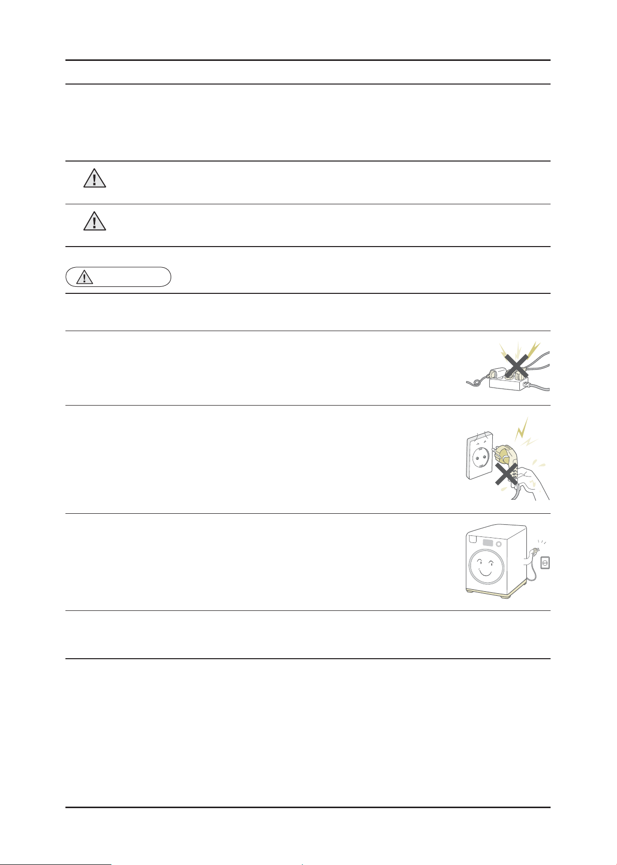
• Do not allow consumers to connect several appliances to a single power outlet at the
same time.
√ There is a risk of fi re due to overheating.
• When removing the power cord, make sure to hold the power plug when pulling the plug
from the outlet.
√ Failing to do so may damage the plug and result in fi re or electric shock.
• When the washing machine is not being used, make sure to disconnect the power plug
from the power outlet.
√ Failing to do so may result in electric shock or fi re due to lightning.
BEFORE SERVICING
• Do not place or use gasoline, thinners, alcohol, or other fl ammable or explosive substances near the washing
machine.
√ There is a risk of explosion and fi re caused from electric sparks.
Safety Instructions _ 1
WARNING
• Check if the power plug and outlet are damaged, fl attened, cut or otherwise degraded.
√ If faulty, replace it immediately.
Failing to do so may result in electric shock or fi re.
• Completely remove any dust or foreign material from the housing, wiring and connection parts.
√ This will prevent a risk of fi re due to tracking and shorts in advance.
• When connecting wires, make sure to connect them using the relevant connectors and check that they are
completely connected.
√ If tape is used instead of the connectors, it may cause fi re due to tracking.
• Make sure to discharge the PBA power terminals before starting the service.
√ Failing to do so may result in a high voltage electric shock.
• When replacing the heater, make sure to fasten the nut after ensuring that it is inserted into the bracket-heater.
√ If not inserted into the bracket-heater, it touches the drum and causes noise and electric leakage.
WHILE SERVICING
WARNING
• Check the wiring.
√ Ensure that no wire touches a rotating part or a sharpened part of the electrical harness.
• Check for any water leakage.
√ Perform a test run for the washing machine using the standard course and check whether there is any water
leakage through the fl oor section or the pipes.
• Do not allow consumers to repair or service any part of the washing machine
themselves.
√ This may result in personal injury and shorten the product lifetime.
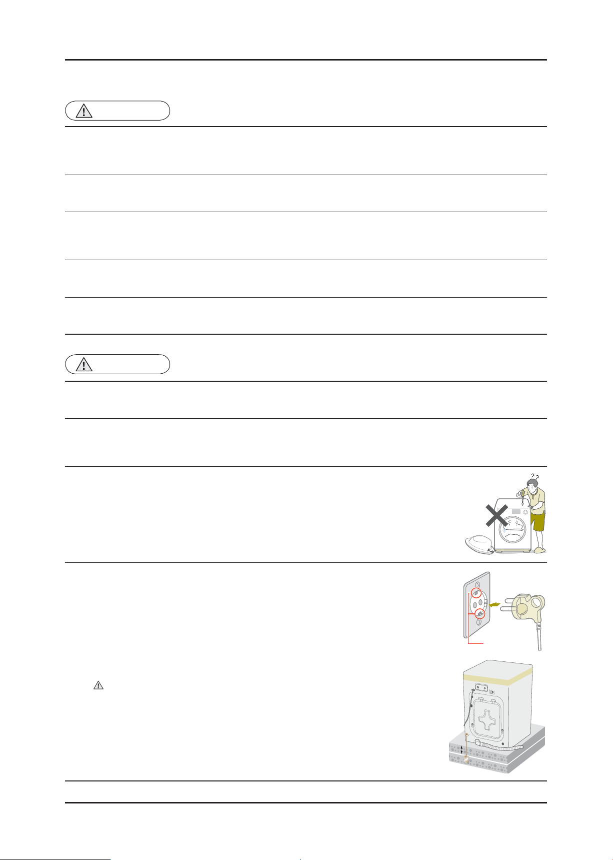
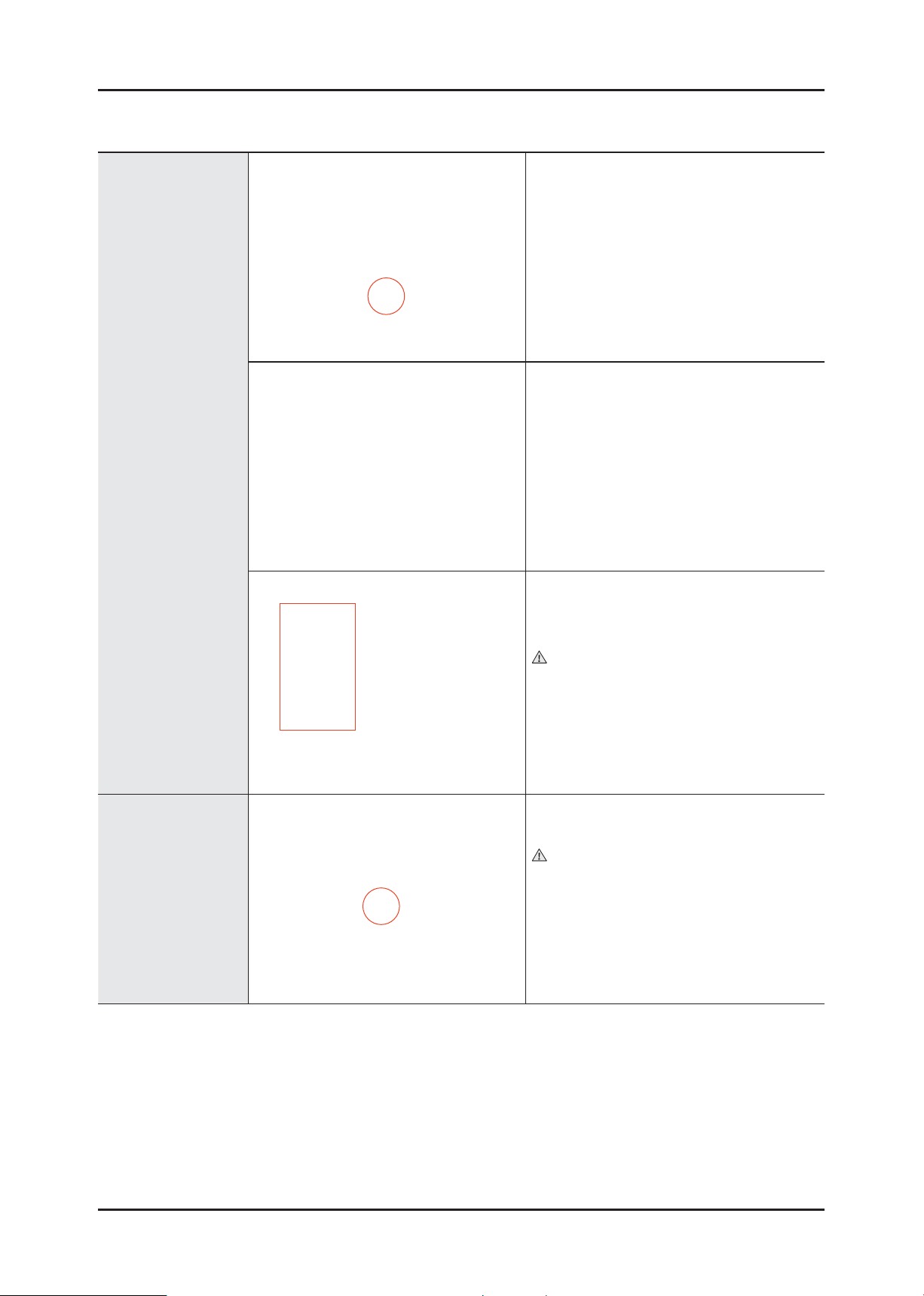
• If it seems that grounding is needed due to water or moisture, make sure to run
grounding wires.
(Check the grounding of the power outlet, and additionally ground it to a metallic water
pipe.)
√ Failing to do so may result in electric shock due to electric leakage.
[Running a grounding wire]
- Twist a grounding wire (copper wire) two or three times around the tap.
- If you connect the grounding wire to a copperplate, bury it 75 cm under the earth in a
place with a lot of moisture.
Do not connect the grounding wire to a gas pipe, plastic water pipe or telephone
wire. There is a risk of electric shock or explosion.
AFTER SERVICING
Grounding
terminal
2 _ Safety Instructions
75 cm
Copperplate

CAUTION
• Do not sprinkle water onto the washing machine directly when cleaning it.
√ This may result in electric shock or fi re, and may shorten the product lifetime.
• Do not place any containers with water on the washing machine.
√ If the water is spilled, it may result in electric shock or fi re. This will also shorten the
product lifetime.
• Do not install the washing machine in a location exposed to snow or rain.
√ This may result in electric shock or fi re, and shorten the product lifetime.
BEFORE SERVICING
• Do not press a control button using a sharp tool or object.
√ This may result in electric shock or damage to the product.
CAUTION
• When wiring a harness, make sure to seal it completely so no liquid can enter.
√ Make sure that they do not break when force is exerted.
• Check if there is any residue that shows that liquid entered the electric parts or harnesses.
√ If any liquid has entered into a part, replace it or completely remove any remaining moisture from it.
WHILE SERVICING
• If you need to place the washing machine on its back for servicing purposes, place a support(s) on the fl oor and lay it
down carefully so its side is on the fl oor.
√ Do not lay it down on its front. This may result in the inside tub damaging parts.
Safety Instructions _ 3
CAUTION
• Check the assembled status of the parts.
√ They must be the same as before servicing.
• Check the insulation resistance.
√ Disconnect the power cord from the power outlet and measure the insulation resistance between the power plug
and the grounding wire of the washing machine. The value must be greater than 10MΩ when measured with a
500V DC Megger
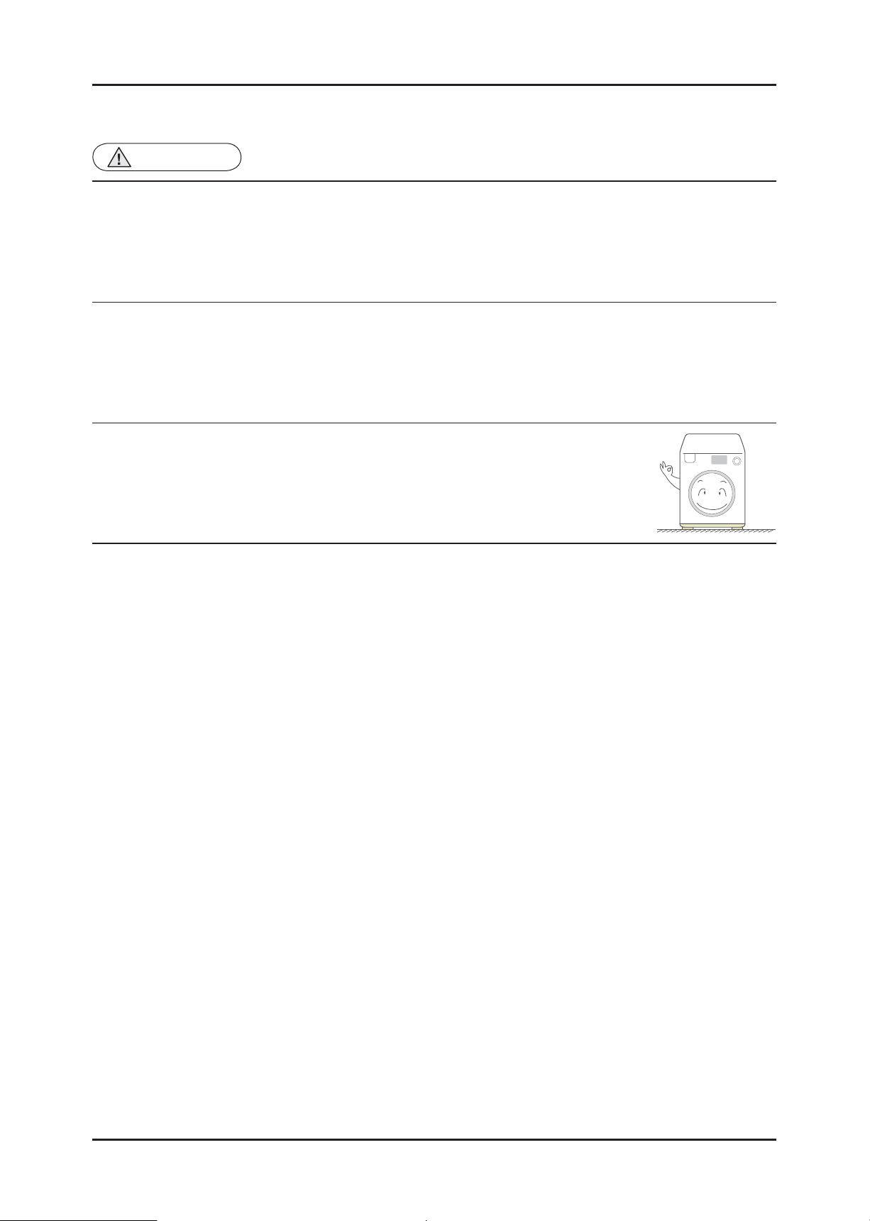
• Check whether the washing machine is level in relationship with the fl oor. Check whether
it is installed fi rmly on the fl oor.
√ Vibrations can shorten the lifetime of the product.
AFTER SERVICING
4 _ Safety Instructions
2. FEATURES AND SPECIFICATIONS
2-1. FEATURES
■ COMMON FEATURES
Features Description
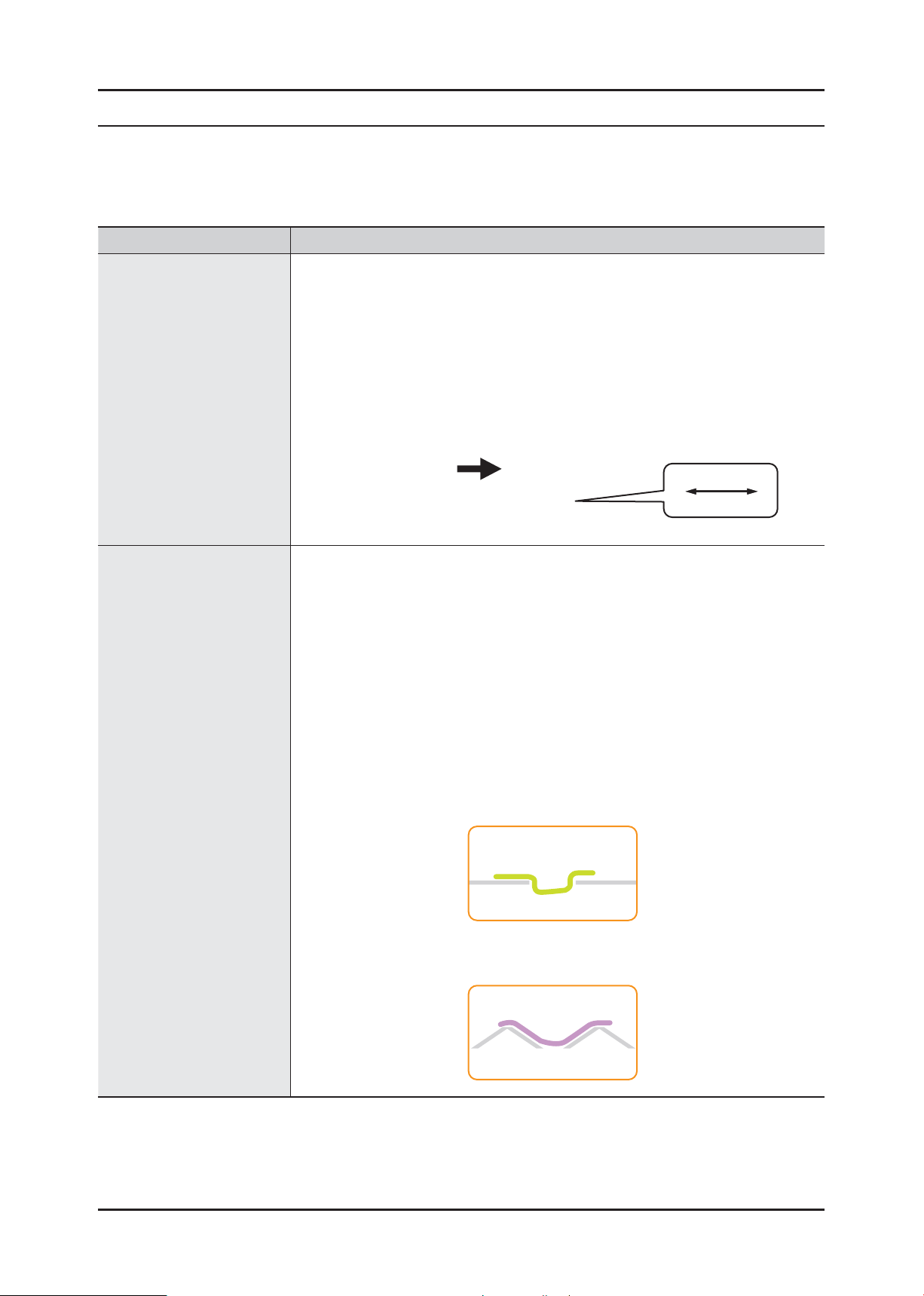
Big Door • This is the maximum capacity to be implemented at the standard 55 cm depth.
- The benefi ts for customers have been greatly increased due to the effi cient
use of limited space.
- Usability has been improved due to the easier loading and removing of the
laundry.
• The size of the loading entry has increased: 300 mm → 330 mm (Wide)
- A lot more washing can be conveniently added and removed.
330 mm
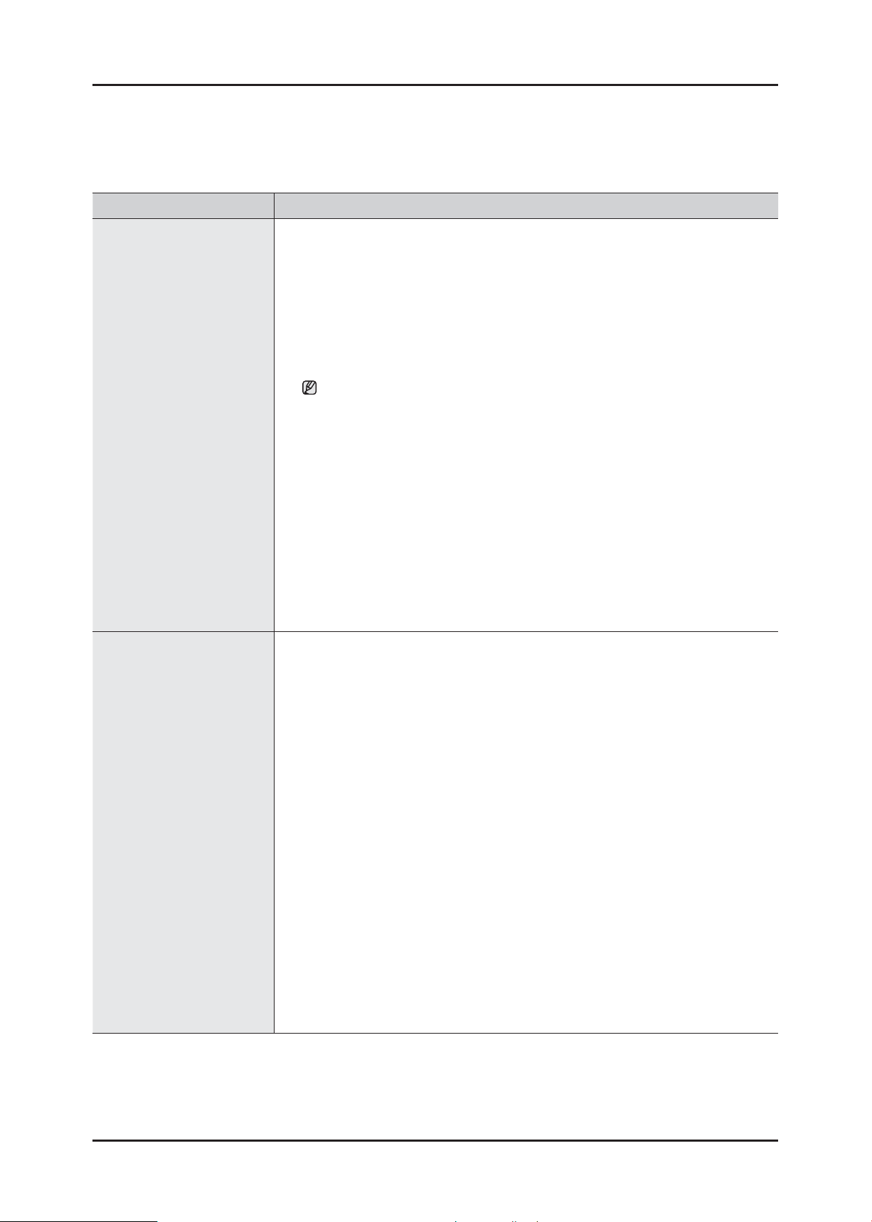
Diamond Drum • The washing performance has increased but potential damage to the washing has
been minimized. (The size of the holes on the diamond drum has been reduced
for minimizing damage to the washing.)
- The embossed wall of the drum serves as a washboard, dramatically
increasing the washing performance compared with existing drum washing
machines, which use the power of the difference in elevation only.
- The size of holes has been reduced drastically, maintaining the optimal wash
performance (Washing Cost 1.0) while saving on water and electricity required
for washing.
- The structure of the holes on the diamond drum has been changed minimizing
potential damage to the washing since it is diffi cult for strands to enter the
holes.
Conventional
Fabric
Diamond Drum
Fabric
Features and Specifi cations _ 5
■ OPTIONAL FEATURES
► The features below depend on the model.
Features Description
Air Refresh System • Sterilization/Deodorization/Removal of Ticks without Water Washing (Air Washing
Using Air and Heating)
- Destroying bacteria and ticks without the use of water
- Removing the sweat and dirt odors
- Maintaining the shape and color of the washing without dry-cleaning
• Washing with air.
- Removing odors by heating, keeping the washing as new.
- Washing with air conveniently, compared with dry-cleaning
The goal of deodorization is 60 percent. (40-minute cycle)
• Washing one or two shirts in 30 minutes
- If a piece of clothes is not completely dry when it is humid, the machine can
dry it within 30 minutes
• Preventing bio-fi lm caused by humidity from occurring
- You do not need to worry about the humidity inside the drum.
- The drum is dried regularly, preventing bio-fi lm.
Water Safety System • The Water Safety System has invented for perfect leakage protection. The double
safety valve connects directly to the water faucet. In the event of a leakage,
the built-in sensor immediately detects the leak within a few short seconds,
automatically turning off both the water supply and the washing machine.
- Inlet hose
It attached to the water supply hose and automatically
cuts off water fl ow when hose damaged. It also
displays a warning indicator.
- Leakage Sensor
A water leakage sensor attached at the bottom of the washing machine to
cutoff the power automatically if a leakage occurs, to prevent danger of a fi re.
6 _ Features and Specifi cations
► The features below depend on the model.
Features Description
Silver Wash System • Samsung’s unique technology generates silver ions that remove bacteria and
fungi, and create an invisible shield that protects your clothes from unwanted
odors until your next wash. Using an ancient and proven purifi cation technique so
simple, yet so advanced it removes microbes even in cold water.
• Effect of Silver Wash System
- Keeps Stored Clothes Fresh
The Ag+ Silver (Nano) Technology anti-bacterial effect keeps fabric free from
odor-causing micro-organisms for up to one month, without the use of strong
chemical cleaners. There’s no need to worry about musty-smelling clothes
even if they remain unused for a long period.
- Makes Shapeless Garments a Thing of the Past
High temperatures and harsh bleaches can damage and discolor your clothes.
The Ag+ Silver (Nano) Technology helps your clothes last longer, without
stretching, shrinking, pilling or fading.
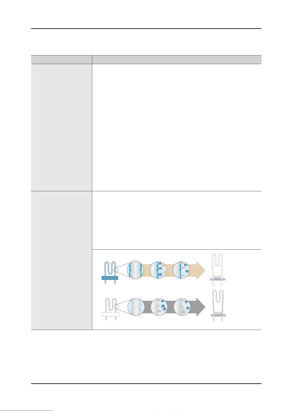
Ceramic Heater • The ceramic heater in Samsung washing machine prevents metals in hard water
from being attach to the heater, which may cause a reduction in heater effi ciency .
It saves energy, time and costs.
- Energy Savings
Over time, conventional heaters increase their power consumption an average
of 5.8 percent, while ceramic heaters only become 1.8 percent less effi cient.
- Time Savings
After three years, conventional heaters take 7.5 percent longer to heat up,
whereas ceramic only lose 2.5 percent longer to heat up, whereas ceramic
only lose 2.5 percent of their ability to heat up.
10 Years
Ceramic
Enlarged
ew
Vi
Producted
Surface
No Build-Up
2.7 Years
Normal
Enlarged
View
Molecules
binding
Scale
Formation
Features and Specifi cations _ 7
► The features below depend on the model.
Features Description
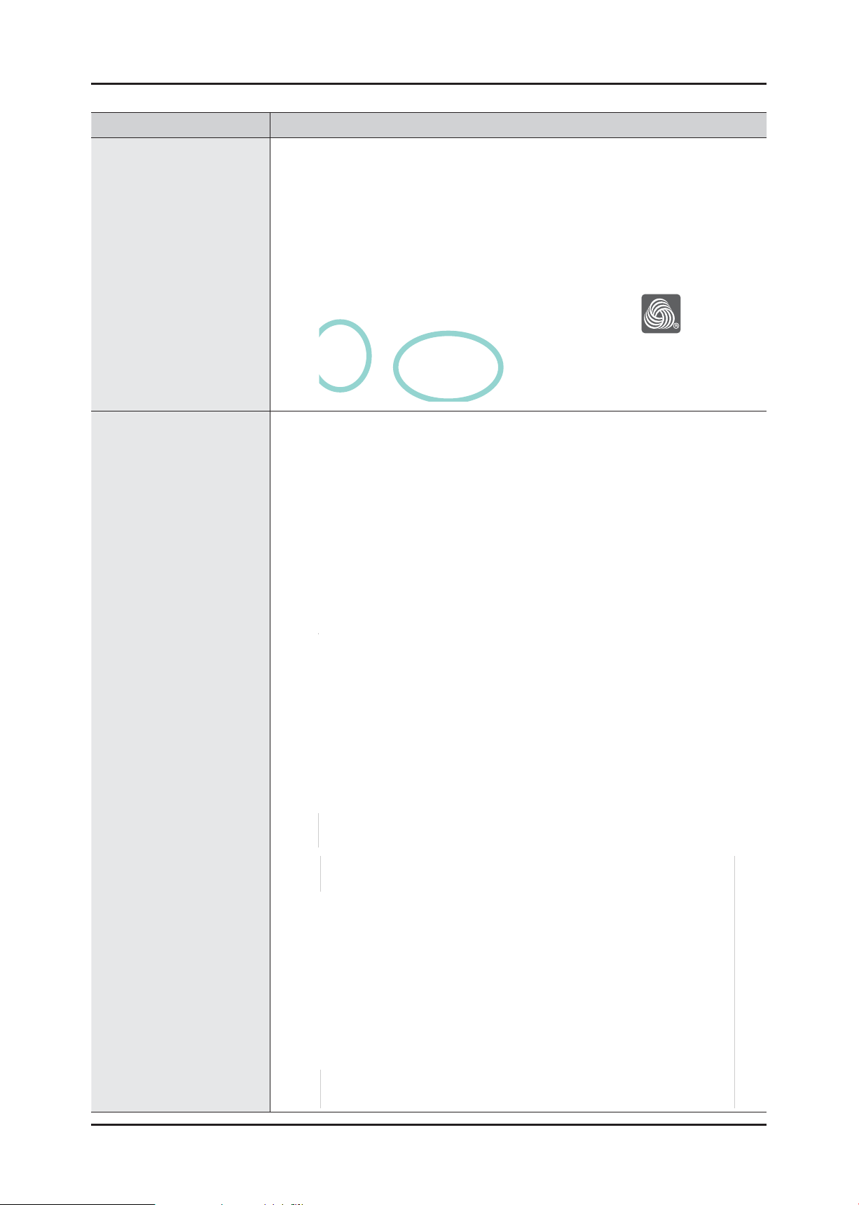
Wool Mark • Fabric Care
- Minimize shrinking
- Gently and carefully cleans
- delicate fabrics that are usually washed by hand.
uG ~GuG ~G
Volt Control • The solution for more Durable and Reliable Washing Machine
- Although you may not see the direct problems of power surges that run
through your electronic devices, a real danger in sudden surges of voltage
does exist and this defi nitely affects your washing machine. This is especially
true for machines that require a lot of energy. Samsung’s Volt Control
guarantees that your washing machine works safely even with voltage
deviations of ±25%.
• What does the “Volt Control” mean?
- This is technology that allows to safe a washing machine from high shock and
even lower voltage. There is an additional protective measure in a washing
machine for your precious clothes. It constantly controls washing cycle in a
fl uctuated situation and re-start automatically when the standard voltage fl ows
back again.
400V
350V
300V
250V
220V
200V
180V
165V
8 _ Features and Specifi cations
400V
350V
300V
250V
220V
200V
180V
165V
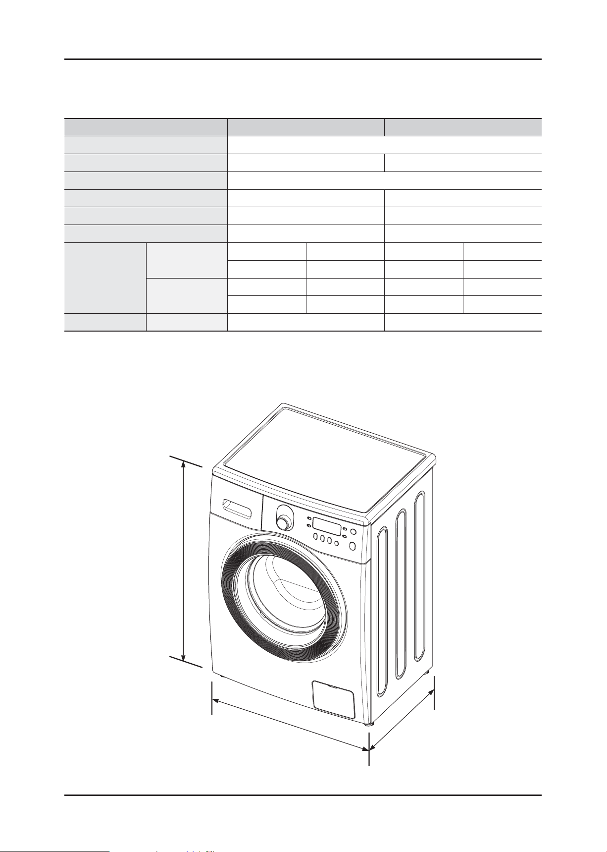
2-2. SPECIFICATIONS
Model WF8654/WF8652/WF8650/WF8658 WF8552/WF8550/WF8558
Wash Type FRONT LOADING TYPE
Dimension W 600 mm X D 550 mm X H 850 mm W 600 mm X D 450 mm X H 850 mm
Water Pressure 50 kPa ~ 800 kPa
Water Volume 48 ℓ 40 ℓ
Weight 59 kg 54 kg
Wash & Spin Capacity 6.5 kg 5.5 kg
WASHING
Power
Consumption
Spin Revolution rpm 1400 / 1200 / 1000 / 800 1200 / 1000 / 800
WASHING and
HEATING
220±15% V 150 W 220±15% V 150 W
240±15% V 150 W 240±15% V 150 W
220±15% V 2000 W 220±15% V 2000 W
240±15% V 2400 W 240±15% V 2400 W
850
600
550
Features and Specifi cations _ 9
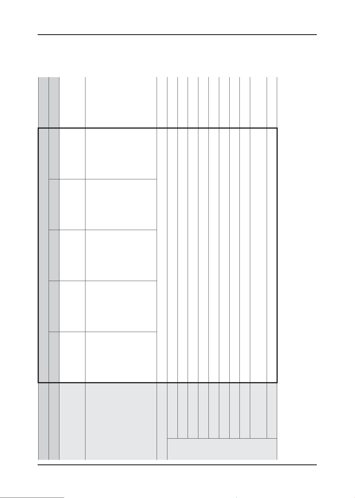
2-3. COMPARING SPECIFICATIONS WITH EXISTING MODELS (5.5 KG WASHER)
(★) : Functions may be different depending on the model.
WF8802*
WF8552NMW
WF8550NMW
WF8558NMW
WF8552NHW
WF8550NHW
WF8558NHW
WF8552SGV
WF8550SGV
WF8558SGV
WF8552NFV
WF8550NFV
WF8558NFV
WF8552SEA
WF8550SEA
WF8558SEA
Universal Universal
Pump Pump
Yes Yes
Grade Best Better Good Basic Flat -
Project AEGIS Heba
Model Name
10 _ Features and Specifi cations
Image
Capacity 5.5 kg 8.0 kg
Max Rpm 1200 / 1000 / 800 1400 / 1200 / 1000
Drum Volume 40 ℓ 64 ℓ
Motor
Control Sys General General
Weight Detection 3 Stages 3 Stages
Heater Capacity 2000 W / 230 V 2000 W / 230 V
Water Supply Cold Only / Cold and Hot Cold Only
Drainage
Main
Spec
Power-outage
Compensation
Zero Standby Power Yes (1W or Less) Yes (1W or Less)
WF8802*
WF8552NMW
WF8550NMW
WF8558NMW
WF8552NHW
WF8550NHW
WF8558NHW
Display
G.LED / Dot
WF8552SGV
WF8550SGV
WF8558SGV
WF8552NFV
WF8550NFV
WF8558NFV
WF8552SEA
WF8550SEA
WF8558SEA
Yes (★) Yes (★)
Yes Yes
ash Yes Yes Yes (★) No Yes (★)
Project AEGIS Heba
Grade Best Better Good Basic Flat -
Model Name
Image
ater Safety Yes (★) Yes (★) No No Yes (★)
W
Ceramic Heater
Diamond Drum Yes Yes
Loading Entry Size Wide (330 mm) Wide (330 mm)
Big Door Yes (460 mm) Yes (480 mm)
Voltage Protector Yes -
Air Refresh No Yes (★)
Silver W
USP
Center Jog Dial
Display G.LED DOT LED DOT LED DOT LED
Design
Dimension (W X D X H mm) 600 X 450 X 850 598 x 600 x 844
Features and Specifi cations _ 11
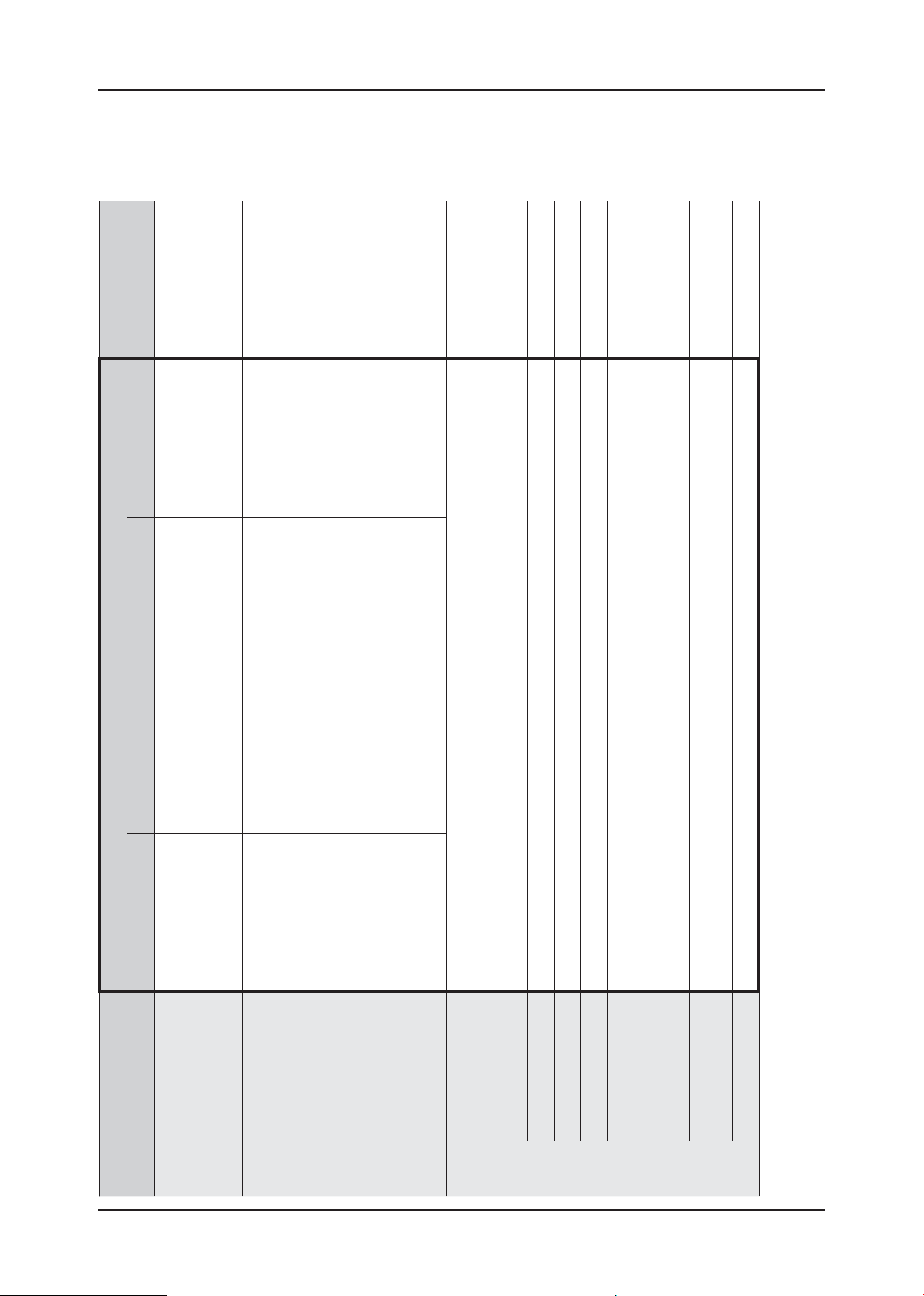
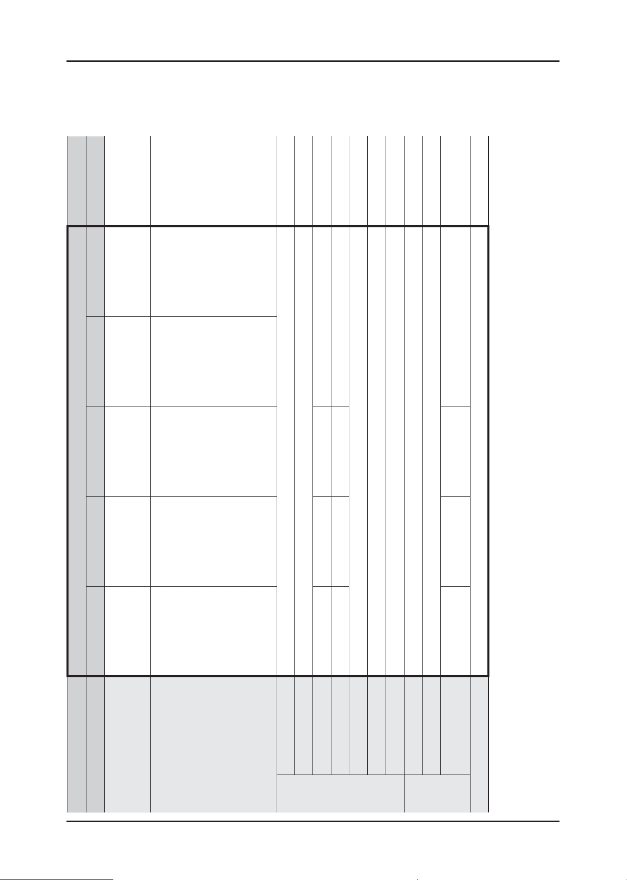
2-4. COMPARING SPECIFICATIONS WITH EXISTING MODELS (6.5 KG WASHER)
(★) : Functions may be different depending on the model.
WF8802*
WF8654NHV
WF8652NHV
WF8650NHV
WF8658NHW
WF8654NGW
WF8652NGW
WF8650NGW
WF8658NGW
WF8654NFV
WF8652NFV
WF8650NFV
WF8658NFV
WF8654SEA
WF8652SEA
WF8650SEA
WF8658SEA
Universal Universal
Pump Pump
Yes Yes
Grade Best Better Good Basic -
Project AEGIS Heba
Model Name
12 _ Features and Specifi cations
Image
Capacity 6.5 kg 8.0 kg
Max Rpm 1400 / 1200 / 1000 / 800 1400 / 1200 / 1000
Drum Volume 48 ℓ 64 ℓ
Motor
Control Sys General General
Weight Detection 3 Stages 3 Stages
Heater Capacity 2000 W / 230 V 2000 W / 230 V
Water Supply Cold Only / Cold and Hot Cold Only
Drainage
Main
Spec
Zero Standby Power Yes (1W or Less) Yes (1W or Less)
Power-outage
Compensation
WF8802*
WF8654NHV
WF8652NHV
WF8650NHV
WF8658NHW
WF8654NGW
WF8652NGW
WF8650NGW
WF8658NGW
Project AEGIS Heba
WF8654NFV
WF8654SEA
Grade Best Better Good Basic -
WF8652NFV
WF8650NFV
WF8658NFV
WF8652SEA
WF8650SEA
WF8658SEA
Model Name
Image
Yes (★) Yes (★)
ash Yes Yes Yes (★) No Yes (★)
Voltage Protector Yes -
Air Refresh No Yes (★)
ater Safety Yes (★) Yes (★) No No Yes (★)
Silver W
W
Diamond Drum Yes Yes
Ceramic Heater
Loading Entry Size Wide (330 mm) Wide (330 mm)
Yes Yes
Big Door Yes (460 mm) Yes (480 mm)
Display G.LED DOT LED DOT LED DOT LED G.LED / Dot Display
Center Jog Dial
USP
Design
Dimension (W X D X H mm) 600 X 550 X 850 598 x 600 x 844
Features and Specifi cations _ 13
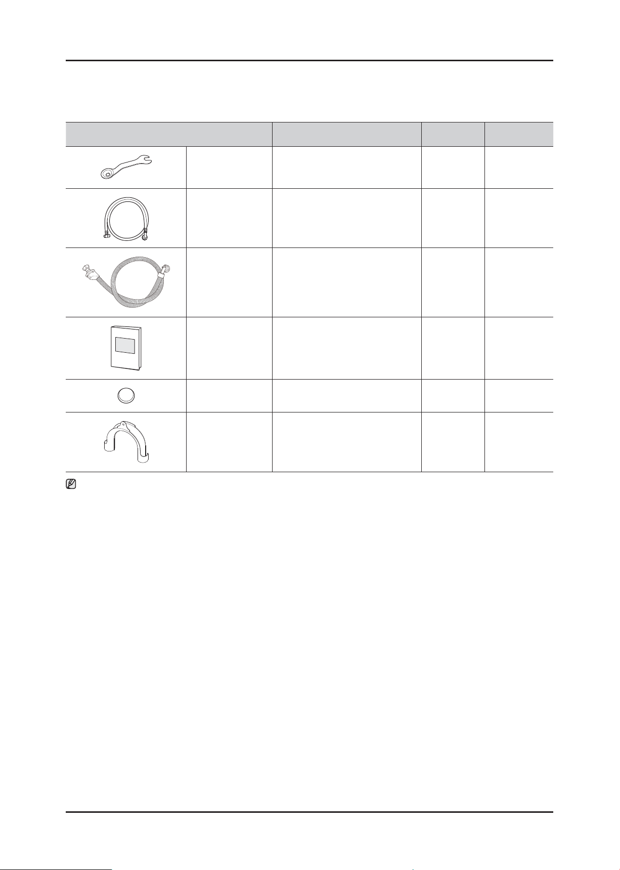
2-5. OPTIONS SPECIFICATIONS
Item Code QTY Remarks
BOLT-SPANER DC60-40146A 1 Default
HOSE-WATER DC62-10289C
HOSE-WATER
(AQUA-STOP)
MANUAL-BOOK DC68-02610D 1 Default
CAP-FIXER DC67-00251A 4 Default
HOSE-HANGER DC62-10278A 1 Default
Note
• (★) is supplied for specifi c models only among those without water supply hoses.
• You can purchase additional water supply and drain hoses from a service center.
• For built-in models, the spanner, water supply and drain hoses are not supplied. Both the water supply and drain
hoses are supplied during the installation.
DC62-00079A
★
★
For specifi c
models only
For specifi c
models only
14 _ Features and Specifi cations
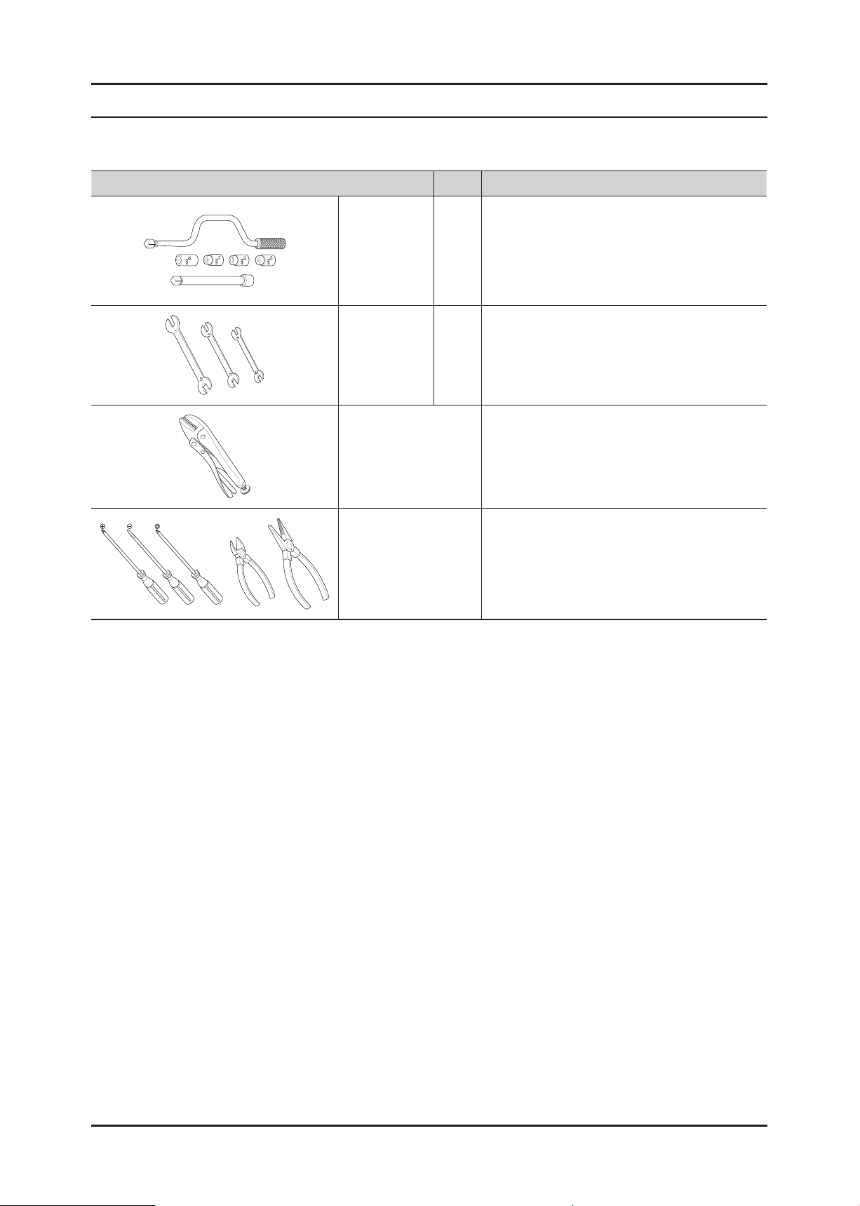
3. DISASSEMBLY AND REASSEMBLY
3-1. TOOLS FOR DISASSEMBLY AND REASSEMBLY
Tool Type Remarks
10mm
Box driver
Double-ended
spanner
Vice pliers
Others
(screwdriver, nipper,
long nose pliers)
13mm
19mm Pulley(1)
10mm
13mm
19mm
Heater(1),Tub(12), Fixer screw(5), Motor(2),
Balance(9)
Shock Absorber (2 holes each in left/right),
Damper(2), Damper(friction 2)
Replaced by box driver
Leg
A Tool for protecting empty turning of bolt or
abrasion from using box driver
For disassembly of Spin drum
Common tools for servicing
Removal and Reassembly _ 15
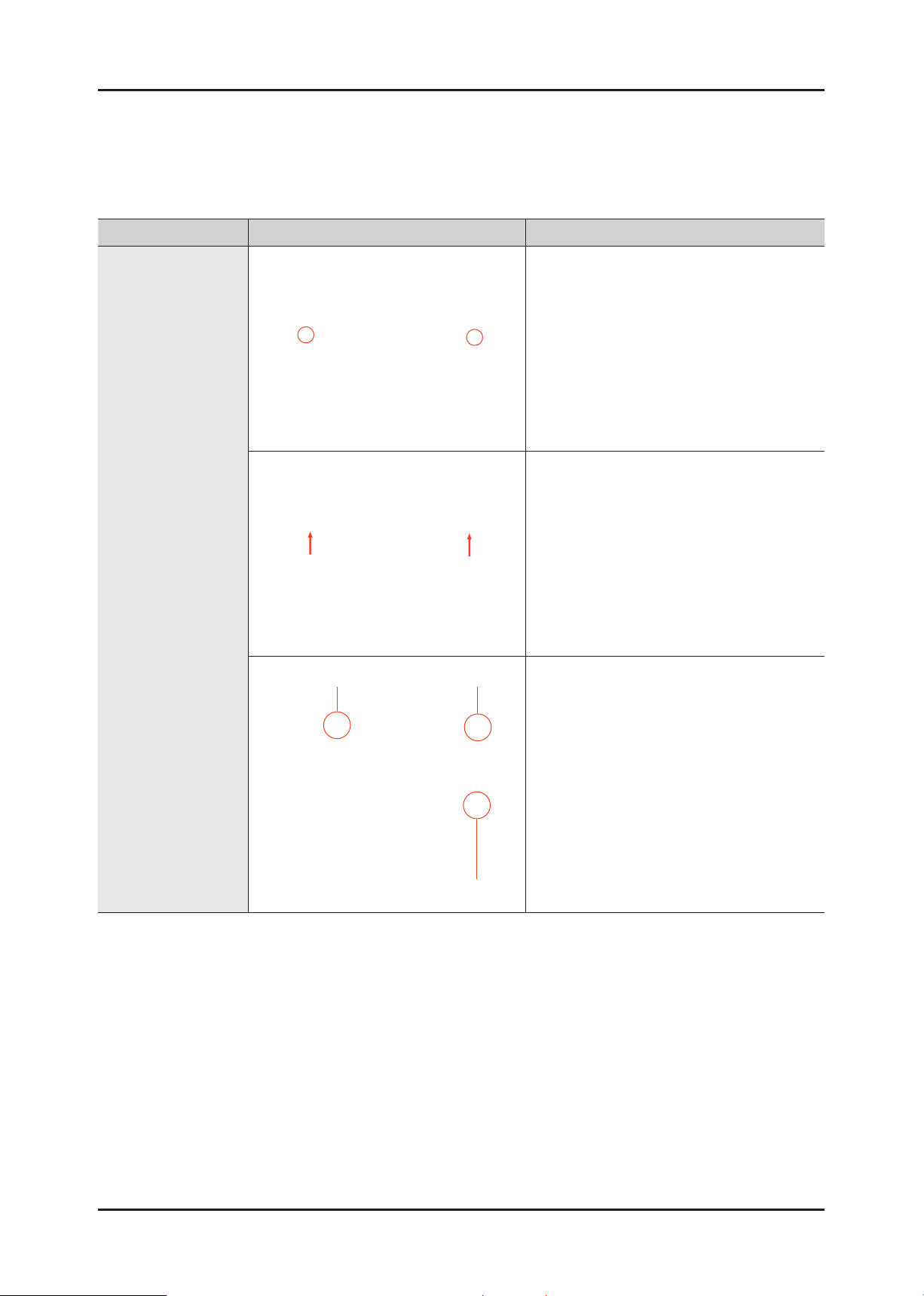
3-2. STANDARD DISASSEMBLY DRAWINGS
► This is a standard disassembly diagram and may differ from the actual product.
Use this material as a reference when disassembling and reassembling the product.
Part Figure Description
1. Remove the two screws holding the Top
Cover at the back of the unit.
2. Remove the top-cover by lifting it up after
pulling it back about 15mm.
ASSY COVER TOP
Water valve Noise fi lter
Sensor pressure
3. Then, the Water (Pressure) Sensor, Noise
Filter and Water Valve can be replaced.
16 _ Removal and Reassembly
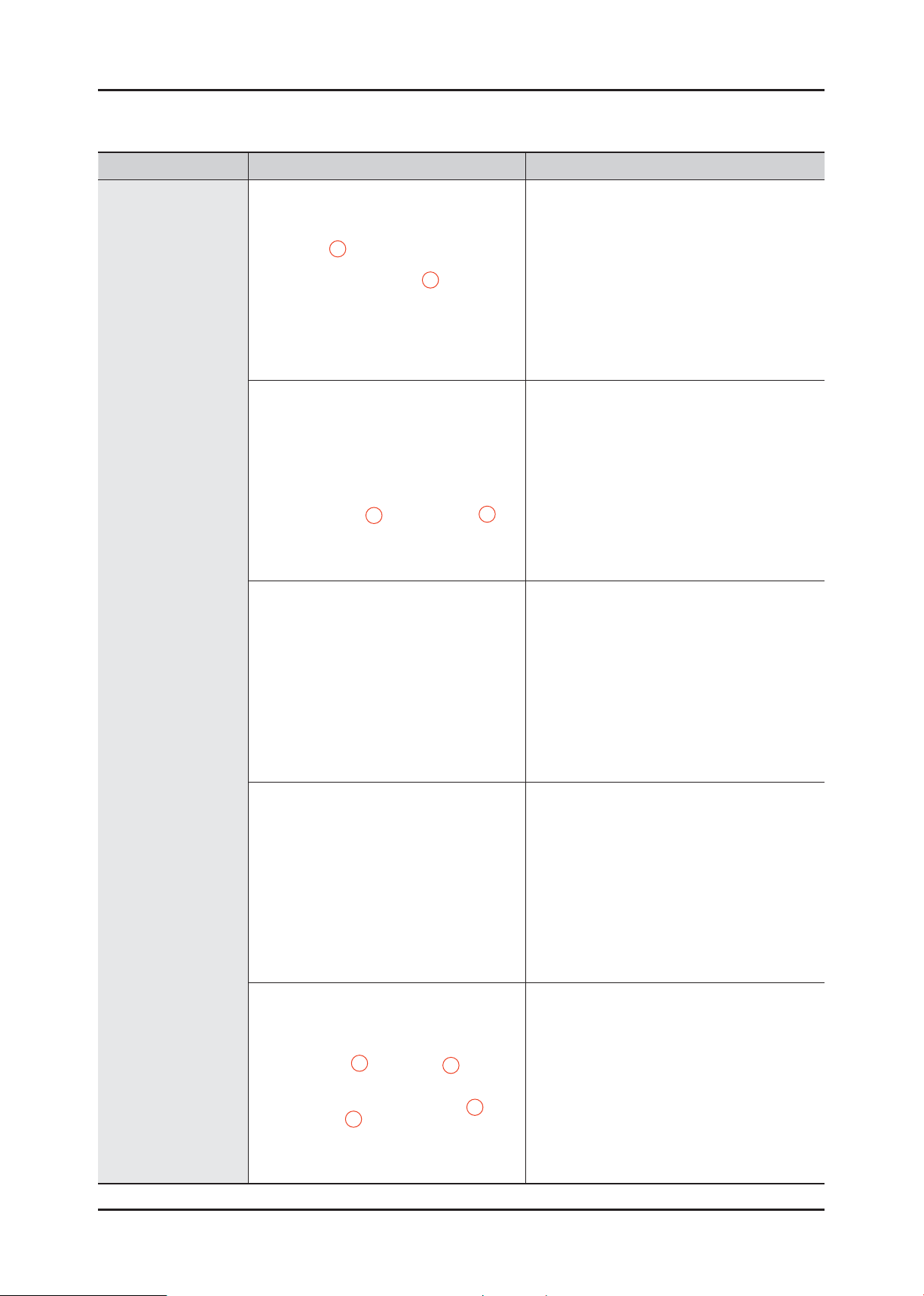
Part Figure Description
1. Remove the 2 screws holding the front
operating panel.
2. Remove the two screws at the top of the
ASSY-PANEL CONTROL.
MAIN-PCB AND
SUB-PCB PANEL
3. Hold the ASSY-PANEL CONTROL while
pulling it upwards and release the hook to
remove it.
4. Disconnect the terminals connected to the
PCB by hand.
5. Remove the four screws holding the PCB
and release the hooks on both sides to
remove the PCB for repair / replacement.
Removal and Reassembly _ 17
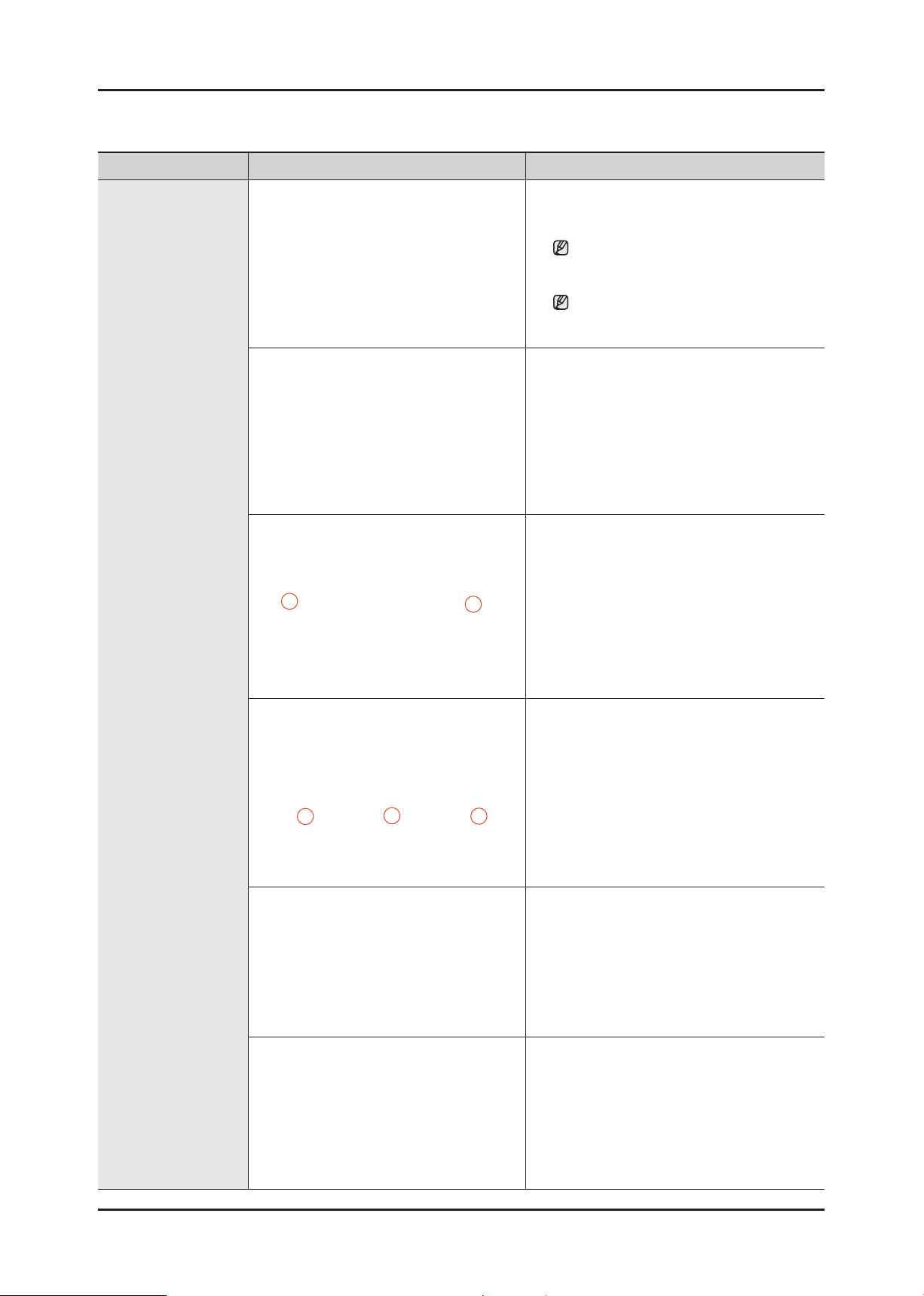
Part Figure Description
1. Open the Door.
Remove the Wire Diaphragm and remove it
from The Front Frame.
For easier disassembly, remove the
spring from the lower part of the
Diaphragm with a (-) screwdriver.
Since the Diaphragm can be damaged
when removing it, remove it slowly in
one direction.
2. Remove the ASSY-CLAMP DIAPHRAGM.
3. Remove the two screws holding the
FRAME-FRONT.
FRAME FRONT
4. Remove the three screws holding the
bottom of the FRAME-FRONT.
5. Disconnect the terminal for the DOORLOCK switch.
6. The DOOR-DIAPHRAGM, HEATER, PUMP,
SHOCK- DAMPER and DOOR LOCK
switch.
18 _ Removal and Reassembly
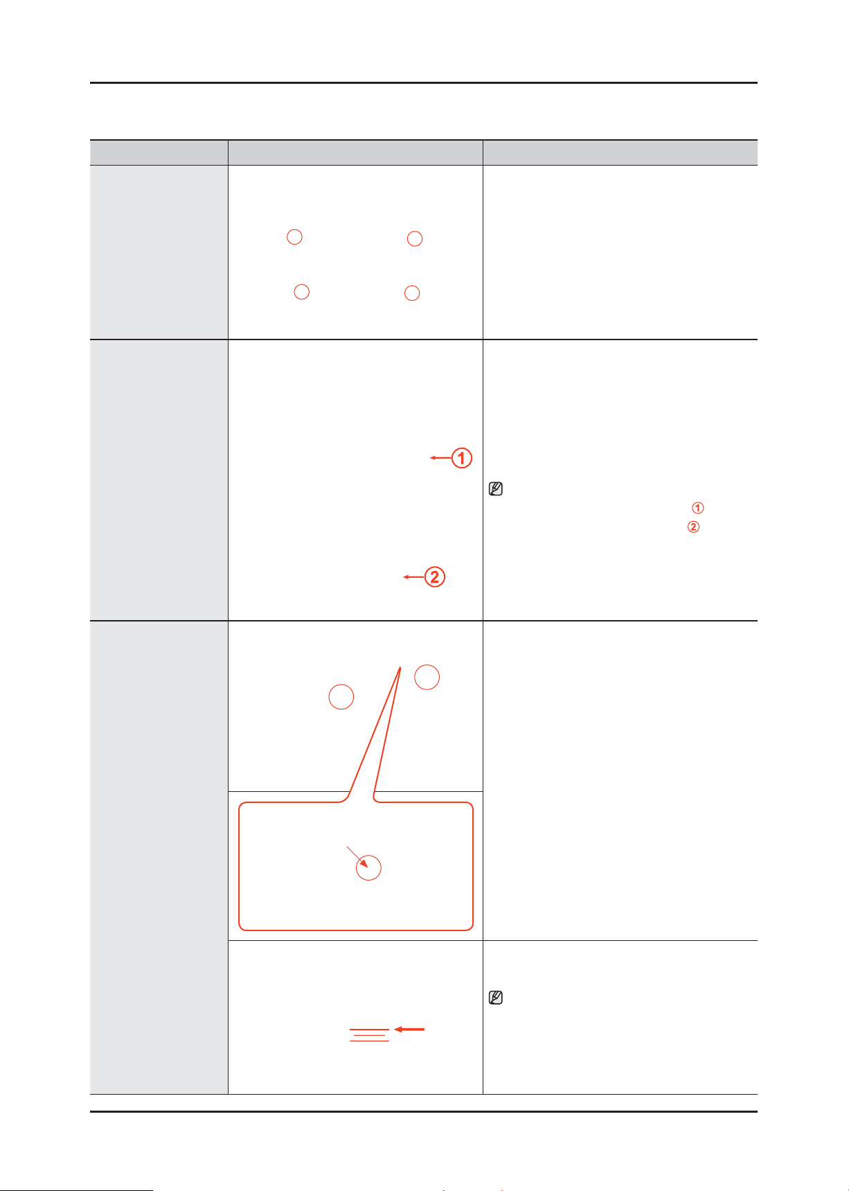
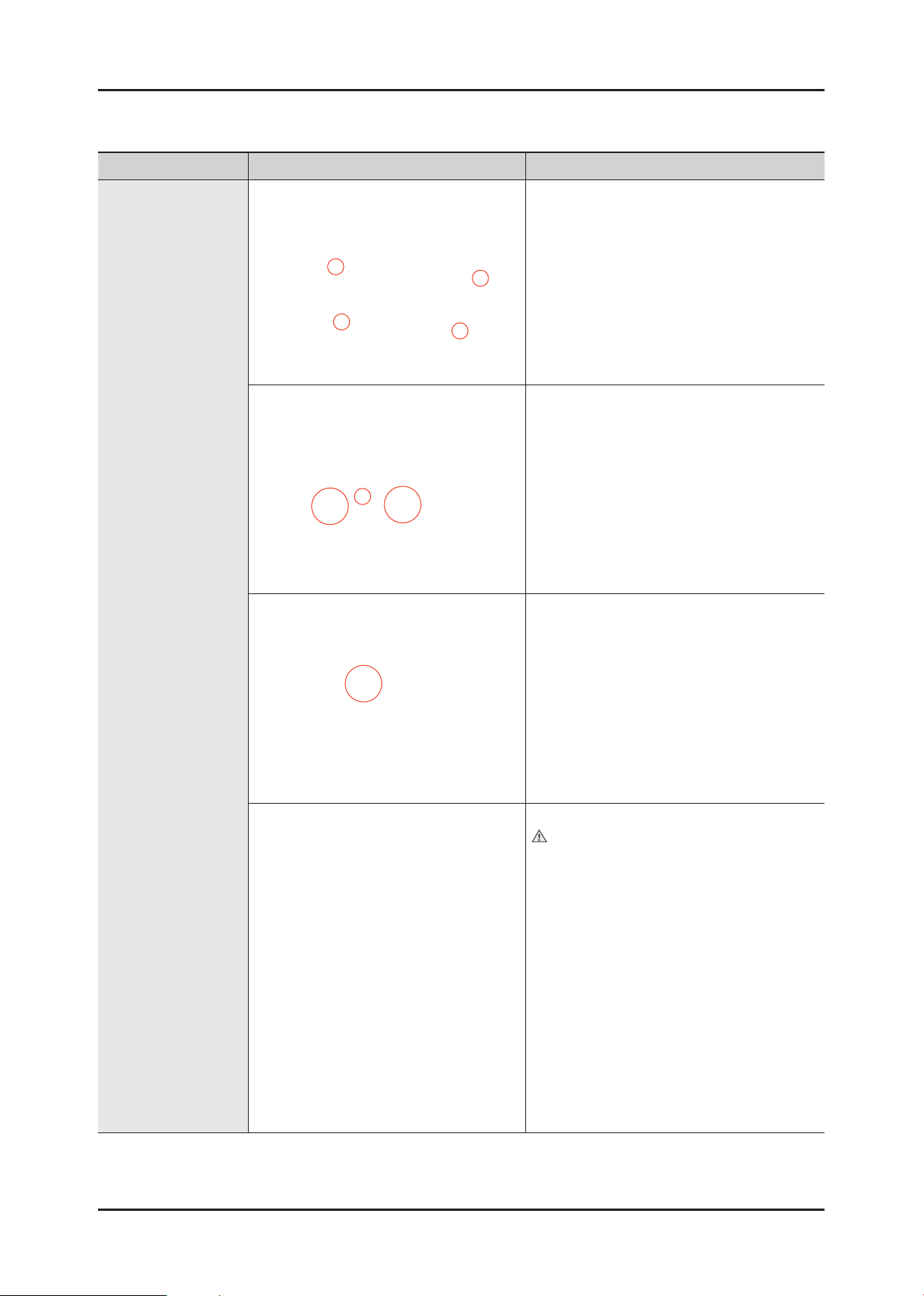
Part Figure Description
COVER-BACK
BELT
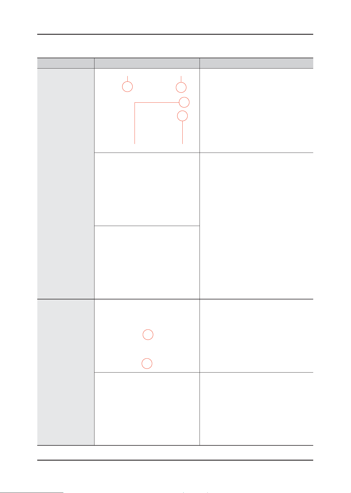
• Remove the 4 screws holding the BackCover at the back of the washing machine.
1. Separate the belt and then assembly it.
2. Check if the belt position is at the center of
the Pulley.
Assembling the belt
Place the belt around the Pulley ( )
and then over the Motor-Pulley (
).
MOTOR
1. Separate the Wire Housing from the motor.
2. Remove the two bolts holding the motor at
the back of the washing machine.
The 2 screws designated ‘A’ which are
inside must be also removed.
3. Separate the motor.
A
When installing the Belt around the Motor
Pulley, the bottom of the belt must be
located on the second fl oor of the Motor
Pulley.
Removal and Reassembly _ 19
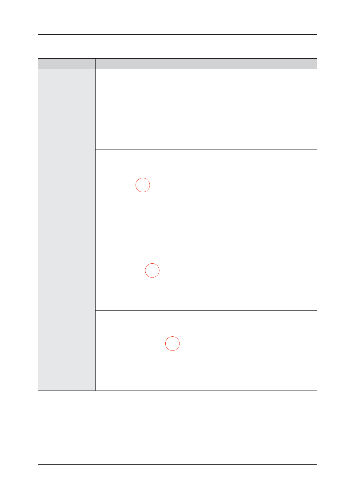
Part Figure Description
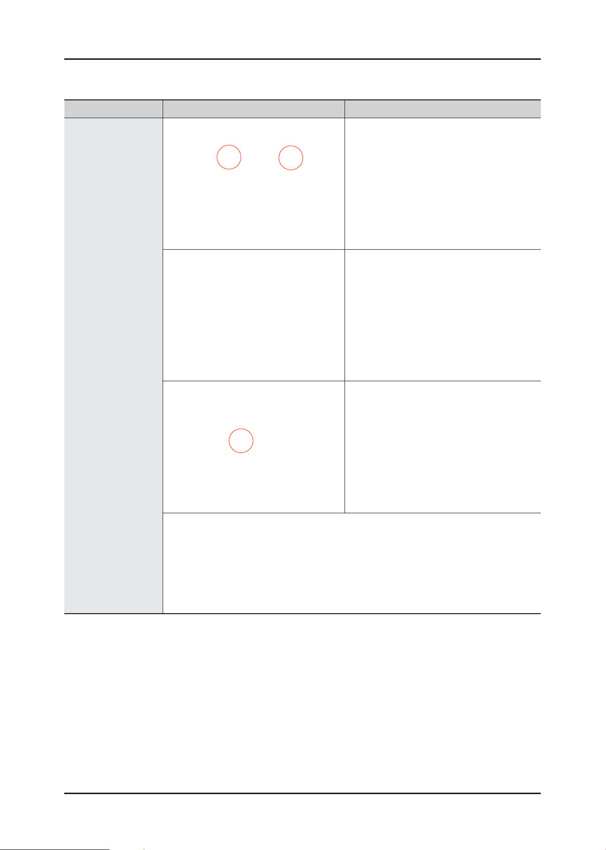
SENSOR PRESSURE
1. Connect the Water-Hose to the main body
of the Pressure-Switch.
2. Fix the Hose-Clamper.
3. Place the Pressure-Switch into the Bracket
Hole holding the main body of the PressureSwitch.
4. To separate the Pressure-Switch, pull the
Pressure-Switch forwards while pushing the
marked part with your fi nger.
20 _ Removal and Reassembly

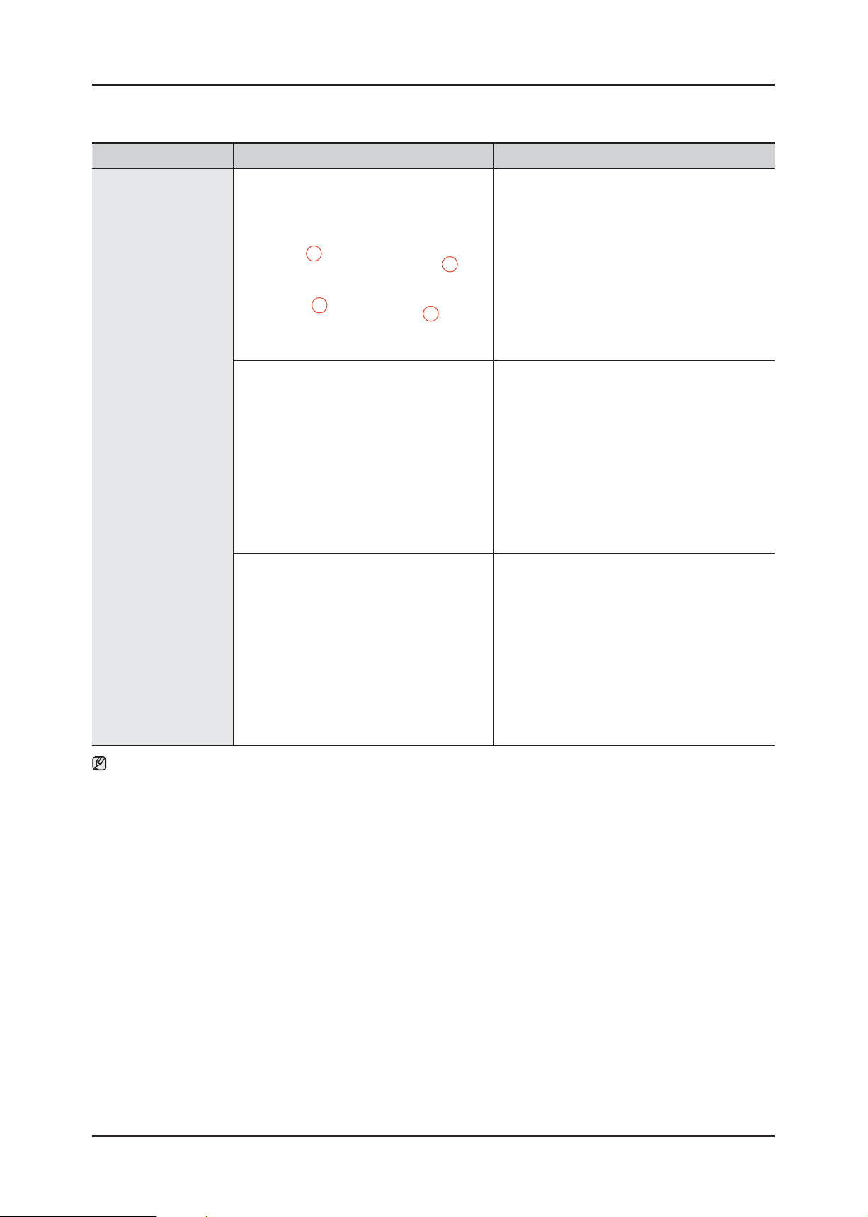
Part Figure Description
1. Separate the Assy cover top.
2. Separate the water supply valve wire.
WATER SUPPLY
VALVE
3. Remove the 2 screws holding the water
supply valve.
DAMPER 1. Remove the 2 screws shown in the fi gure.
Removal and Reassembly _ 21
1. Assemble the bracket-diaphragm and the
diaphragm.
DOOR-DIAPHRAGM
HOSE-FILTER TUB
2. Check if there is a hole in the displayed
panel.
Disassembly and Reassembly of Clamp-Assy
Diaphragm
Check if there is a marking before fi xing Clamp-
Assy Diaphragm.
Caution
Take care when disassembling or
reassembling the product, as the direction
the screws turn used for this product differs
from the standard direction for screws.
1. To disassemble it, turn the screw clockwise.
2. To reassemble it, turn the screw
counterclockwise.
Disassembling and Reassembling the HoseJoint Clamper
Caution
Take care when disassembling or
reassembling the product, as the direction
the screws turn used for this product differs
from the standard direction for screws.
1. To disassemble it, turn the screw clockwise.
2. To reassemble it, turn the screw
counterclockwise.
22 _ Removal and Reassembly
Part Figure Description
Water valve Noise fi lter
1. Separate the Top Assy-Plate.
Sensor pressureASSY-AG PCB
ASSY-AG PCB
and
WATER LEVEL
SENSOR
2. Remove the screw holding the water level
sensor.
DOOR-HINGE
1. Remove the 2 screws holding the Door
Hinge and separate the door.
2. Remove the 11 screws holding the Holder
Glass, separate the Holder Glass and
replace the hinge.
Removal and Reassembly _ 23

Part Figure Description
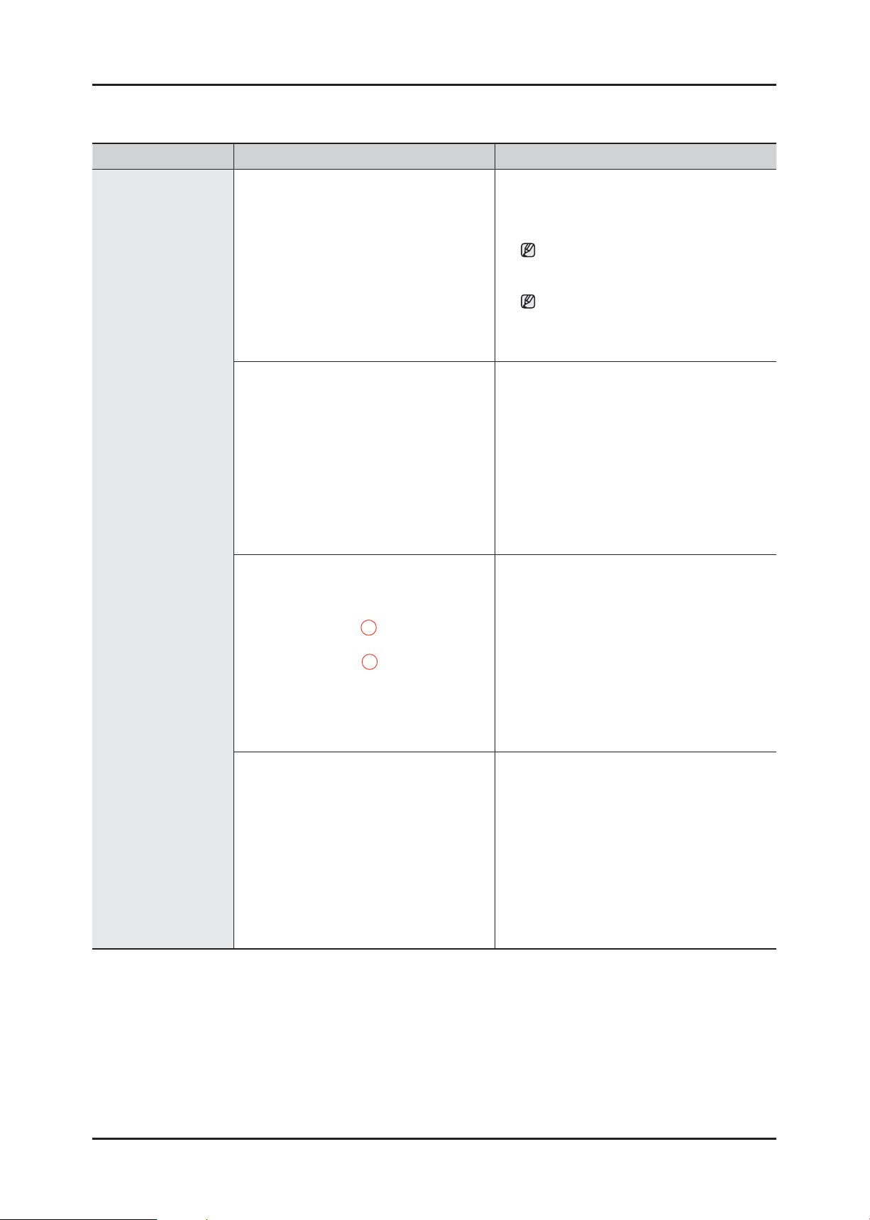
1. Insert the (-) screwdriver into the upper part
of the Filter Cover and push it downwards
to release the catch.
2. Remove the remaining water through the
drainage hose.
Place a bowl under the drainage hose,
or the remaining water may fl ow out.
DRAIN PUMP
3. Separate the Drain Filter by turning it
counterclockwise.
Since the remaining water may fl ow
out, place a bowl underneath it when
separating the fi lter..
4. Remove the 1 screws holding the Drain
Pump.
5. Remove the remaining water through the
drainage hose.
24 _ Removal and Reassembly
Part Figure Description
6. Release the BAND RING (2EA) to remove
the HOSE (2EA).
7. Push the TUB inwards slightly to remove
the PUMP.
DRAIN PUMP
8. Disconnect the wires (2EA).
4 Check Points for Troubleshooting
1. Separate the Drain Filter and check if any alien substances are inside the pump (e.g.
coins, buttons .., etc.) → Remove these if found.
2. Check if the wire driving the pump is has come loose → Take the relevant countermeasure
if necessary.
3. When water leaks, check the assembly status of the Clamp Hose, and Cap Drain → Take
the relevant countermeasure if necessary.
Turn the fi lter counterclockwise to remove the remaining water.
Removal and Reassembly _ 25
Part Figure Description
1. Open the Door.
Remove the Wire Diaphragm and remove it
from The Front Frame.
For easier disassembly, remove the
spring from the lower part of the
Diaphragm with a (-) screwdriver.
Since the Diaphragm can be damaged
when removing it, remove it slowly in
one direction.
2. Remove the ASSY-CLAMP DIAPHRAGM.
DOOR-LOCK S/W
3. Remove the two screws.
4. Remove the screw holding the Door-Lock
S/W.
Remove the Door-Lock S/W.
Remove the connection wire.
(Remove the connector after releasing it by
pressing the catch.)
26 _ Removal and Reassembly
Part Figure Description
1. Separate the Back Cover.
2. Separate the Connection Housing (3).
HEATER
3. Remove the nut holding the heater and
separate the Heater.
4. Remove the Heater from the Tub.
Caution
Make sure to insert
the Heater into the
correct position of
the bracket inside
the Tub when
reassembling it.
Otherwise, there is
a danger of a fi re.
Make sure to push it inwards until the
packing part comes into the Tub completely
when reassembling it so that the packing
part is completely stuck to the Tub.
Fasten the holding nut with a force of 5Kgf/
cm2.
If the nut is not fastened properly, there is a
danger of water leaking.
Removal and Reassembly _ 27
Part Figure Description
1. Separate the Back Cover.
Water-safety
Reassembly is in the reverse order of the removal.
2. Remove the 2 screws.
3. Assemble the 2 housings of the Assy-wire
harness.
28 _ Removal and Reassembly
 Loading...