

Samsung WF80F7E6U6W User manual
Mira Azora
9.8 kW
These instructions must be left with the user
Installation and User Guide
1
For SPARES, ADVICE
or REPAIRS
Please call us on
0844 571 5000
(UK Only)

INTRODUCTION
Thank you for purchasing a quality Mira product. To enjoy the full potential of your
new product, please take time to read this guide thoroughly. Having done so, keep
it handy for future reference.
The Mira Azora is a thermostatic electric shower with separate controls for power
selection and temperature/ow adjustment. A unique thermostatic valve stabilises
temperature changes caused by water pressure uctuations. These can result from
taps being turned on or off, or a toilet being ushed. An individual light indicates
“START/STOP”.
The Mira Azora comes complete with a set of Mira Energise Shower Fittings.
Mira Azora 9.8 kW
A 9.8 kW 240 V AC (9.0 kW 230 V AC) heater with Mira Energise adjustable spray
handset with four different spray actions (start, soothe, force and eco*). Supplied
complete with exible hose, clamp bracket assembly, slide bar, supports, hose
retaining ring and soap dish.
* The ‘eco’ setting will have no effect, and will give the same spray action as the
‘start’ setting.
Guarantee
For domestic installations, Mira Showers guarantee the Mira Azora 9.8 kW against
any defect in materials or workmanship for a period of two years from the date of
purchase (shower ttings for one year).
For non-domestic installations, Mira Showers guarantee the Mira Azora 9.8 kW
against any defect in materials or workmanship for a period of one year from the
date of purchase.
For terms and conditions refer to section “Customer Services”.
Patents and Design Registration
Design Registration: 000578463-001-002
Patents: GB: 2 341 667, 2 404 000, 2 428 286, 2 427 460
Ireland: 82835, 85128, 85163
If you experience any difculty with the installation or operation of your new Electric
Shower, please refer to ‘Fault Diagnosis’, before contacting Kohler Mira Ltd.
Our telephone and fax numbers can be found in the back of this guide.
2

IMPORTANT SAFETY INFORMATION
WARNING - This shower can deliver scalding temperatures if not operated,
installed or maintained in accordance with the instructions, warnings and
cautions contained in this guide and on or inside the appliance.
TO REDUCE THE RISK OF FIRE, ELECTRIC SHOCK OR INJURY:
1. Installation of this shower must be carried out in accordance with these
instructions by qualied, competent personnel.
2. Isolate the electrical and water supplies before commencing installation. The
electricity must be isolated at the consumer unit and the appropriate circuit
fuse removed, if applicable. Mains connections are exposed when the cover
is removed.
3. DO NOT install the shower in areas with high humidity and temperature
(i.e. steam rooms and saunas).
4. DO NOT install the shower where it may be exposed to freezing conditions.
Ensure that any pipework that could become frozen is properly insulated.
5. DO NOT switch the shower on if there is a possibility that the water in the
shower is frozen.
6. DO NOT switch the shower on if water starts leaking from the shower case.
Isolate the electrical supply to the shower immediately.
7. DO NOT connect the outlet of the shower to any tap, control valve, trigger
handset or showerhead other than those specied for use with this shower -
scalding water temperatures and product damage will occur. Only Kohler Mira
recommended accessories should be used.
8. The water supplies to this product must be isolated if the product is not to be
used for a long period of time. If the product or pipework is at risk of freezing
during this period they should also be drained of water.
9. DO NOT perform any unspecied modications to the shower or it’s accessories.
When servicing only use Genuine Kohler Mira replacement parts.
10. If the shower is dismantled during installation or servicing then upon completion
the product must be inspected to ensure all electrical connections are tight and
that there are no leaks.
11. Read all installation instructions before installing this shower.
12. Upon completion of the installation, make sure that the user is familiar with the
operation of the shower, and leave this guide with the owner.
3
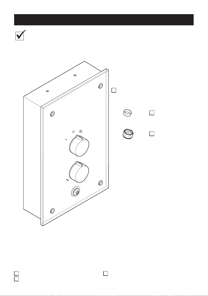
PACK CONTENTS CHECKLIST
Tick the appropriate boxes to familiarise yourself with the part names and to
conrm that the parts are included.
Mira Azora
1 x Mira Azora
1 x Olive
1 x Compression Nut
Documentation
1 x Installation and User Guide 1 x Installation Template
1 x Guarantee and Registration Document
4
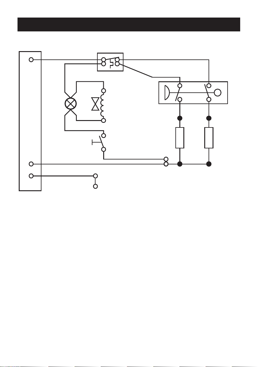
WIRING DIAGRAM
Thermal Cutout
Disc
L
BROWN
RED
Start/Stop
L.E.D.
BROWN
BROWN
Pressure/Power
Selector Switch
Solenoid
Valve
BROWN
BROWN
RED
BLACK
BLACK
START/STOP
BLUE
N
E
GREEN
GREEN
Tank Connection
Inlet Connector
BLUE
Load
BROWN
BLACK
RED
Internal Wiring Diagram
5

SPECIFICATIONS
European Conformity Information
The Mira Azora shower complies with the following European directives:
2006/95/EC Low Voltage Directive, 2004/108/EC EMC Directive.
The Mira Azora shower is a high power appliance and is subject to conditional
connection. If the main electrical supply fuse is rated less than 80 Amps, the local
electricity supply company must be contacted to conrm if the electrical supply is
adequate.
The Mira Azora shower complies with the requirements of the UK’s water regulations.
Plumbing
Minimum Dynamic Pressure 70 kPa (0.7 bar)
Maximum Dynamic Pressure 500 kPa (5 bar)
Maximum Static Pressure 1000 kPa (10 bar)
Minimum Static Pressure 20 kPa (0.2 bar)
Maximum Inlet Temperature 30°C
Minimum Inlet Temperature 2°C
Inlet Connection 1/2” BSP Male / 15 mm Compression Fitting
Maximum Water Hardness 200 ppm CaCO
Outlet Connection 1/2” BSP Male
Azora 9.8
3
Variant
Variant
Electrical
Nominal Power at 230 V ac 9.0 kW
Nominal Power at 240 V ac 9.8 kW
Recommended MCB Rating 45 A
Maximum Supply Cable Size 16 mm²
Recommended RCD Rating 30 mA tripping current
Recommended Isolator Switch 45 A double-pole with 3 mm contact separation
Appliance Sealing Rating IP X4 - Suitable for installation in Zone 1
Maximum Ambient Temperature 30°C
Minimum Ambient Temperature 2°C
Azora 9.8
Dimensions
Height 367 mm
Width 233 mm
Depth 100 mm
6

INSTALLATION REQUIREMENTS
Please read the Important Safety Information and specications sections at
the front of this guide, and the requirements detailed in this section before
installing the shower.
WARNING - TO REDUCE THE RISK OF FIRE, ELECTRIC SHOCK OR INJURY:
Plumbing
1. The plumbing installation must comply with all national or local water regulations
and all relevant building regulations, or any particular regulation or practice
specied by the local water supply company.
2. Do not install the product in a position in which service access is limited.
3. Decide on a suitable position for the shower (minimum distance of 200 mm from
the ceiling to allow for cover t and removal).
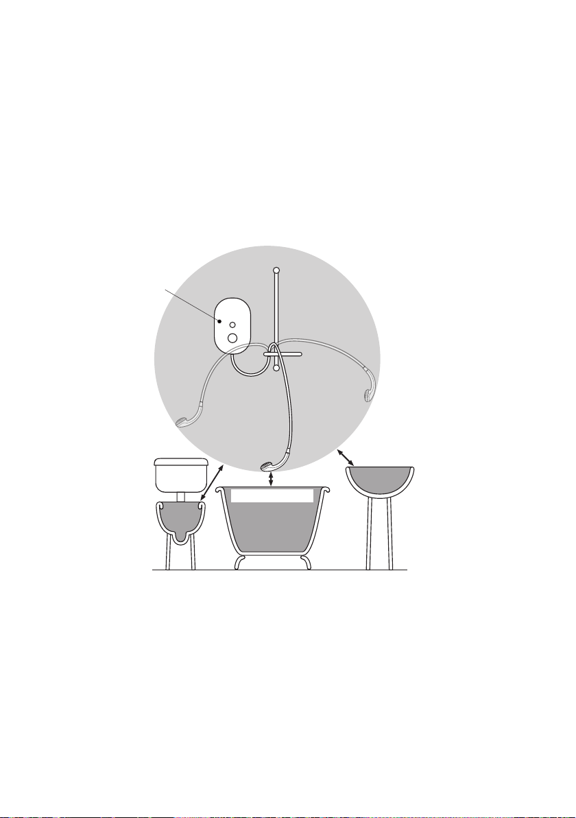
4. The position of the shower and shower ttings must provide a minimum gap of
25 mm between the showerhead and the spill over level of any bath, shower
tray or basin and a minimum gap of 30 mm between the showerhead and the
spill over level of any toilet, bidet or other appliance with a Fluid Category 5
backow risk (see diagram on page 8).
5. The shower is suitable for installation within the shower area and is tted with
a pressure relief valve. It must be positioned over a water catchment area with
the controls at a convenient height for the user.
6. The shower must be tted to a waterproof at and even wall surface.
7. DO NOT t the shower to the wall and tile up to the case.
8. DO NOT seal the gap between the shower and the wall surface.
9. The showerhead should be positioned so that it discharges down the centre
line of the bath or across the opening of a shower cubicle.
10. The showerhead must be directed away from the shower unit, during normal
use the showerhead must not spray directly on to the shower unit.
11. DO NOT apply excessive force to plumbing connections; always provide
mechanical support when making plumbing connections. Any soldered joints
should be made before connecting the shower.
12. This shower is not designed to be plumbed directly from the rear. For rear-entry
supply, add an elbow to the supply pipe and connect as a rising or a falling supply.
13. If pipework and/or electrical cables enter the shower from the rear through a
hole in the wall provision must be made to prevent water ingress back into the
wall structure.
14. Only use the inlet connector supplied with the shower. DO NOT use any other
type of tting.
7
15. A full bore/non restrictive servicing valve must be tted in a readily accessible
position adjacent to the shower to facilitate maintenance of the shower.
DO NOT use a valve with a loose washer plate (jumper) as this can lead to a
build up of static pressure.
16. A water treatment device should be installed where the water hardness may
exceed 200 ppm. Malfunctions caused by excessive limescale formation are
not covered by this shower’s guarantee (see back page for details).
17. The installation must not cause the hose to be sharply kinked during normal
use.
18. DO NOT perform the electrical installation until the plumbing has been
completed and checked for leaks.
Electric
Shower
Zone of
Backow Risk
25 mm
Minimum
30 mm
Minimum
25 mm Minimum
Toilet or Bidet
FC5
Bath or Shower
Tray FC3
Hand Basin
FC3
Hose Retaining Ring tted and shower ttings xed at a suitable height preventing
dirty water backow.
Note! There will be occasions when the hose retaining ring will not provide a suitable
solution for Fluid Category 3 installations, in these instances an outlet double
checkvalve must be tted, this will increase the required supply pressure typically
by 10kPa (0.1 bar). Double checkvalves tted in the inlet supply to the appliance
cause a pressure build up, which could exceed the maximum static inlet pressure
for the appliance and must not be tted. For Fluid Category 5 double checkvalves
are not suitable.
8
WARNING - TO REDUCE THE RISK OF FIRE, ELECTRIC SHOCK OR INJURY:
Electrical
1. The electrical installation must comply with BS 7671 (commonly referred to as
the IEE Wiring Regulations) and all relevant building regulations, or any particular
regulation or practice specied by the local electricity supply company.
2. Ensure that all circuit protection devices, switches and cabling is adequate
for the rated current of the shower and that the rating of the electricity supply
company fuse and the consumer unit are adequate for the additional demand.
3. The shower must be earthed. Ensure any supplementary bonding complies
with the relevant regulations.
4. This shower is intended to be permanently connected to the xed electrical wiring
of the mains system. A separate supply must be provided from the consumer
unit to the shower.
5. DO NOT supply any other electrical equipment including extractor fans or pumps
via this product.
6. This shower must be provided with means for local disconnection that is
incorporated into the xed wiring in accordance with the relevant local wiring
regulations. This must be a double pole switch, which has at least 3 mm contact
separation in each pole. The switch can be a ceiling mounted pull-cord type within
the shower room or a wall mounted switch tted in the applicable zone area.
7. A 30mA Residual Current Device (RCD) is recommended to be tted in the
circuit to the shower.
8. DO NOT apply excessive force to the terminal block.
9. All electrical connections should be checked for tightness to prevent overheating
before switching on the electrical supply.
10. DO NOT switch on the electrical supply until the plumbing has been completed
and checked for leaks.
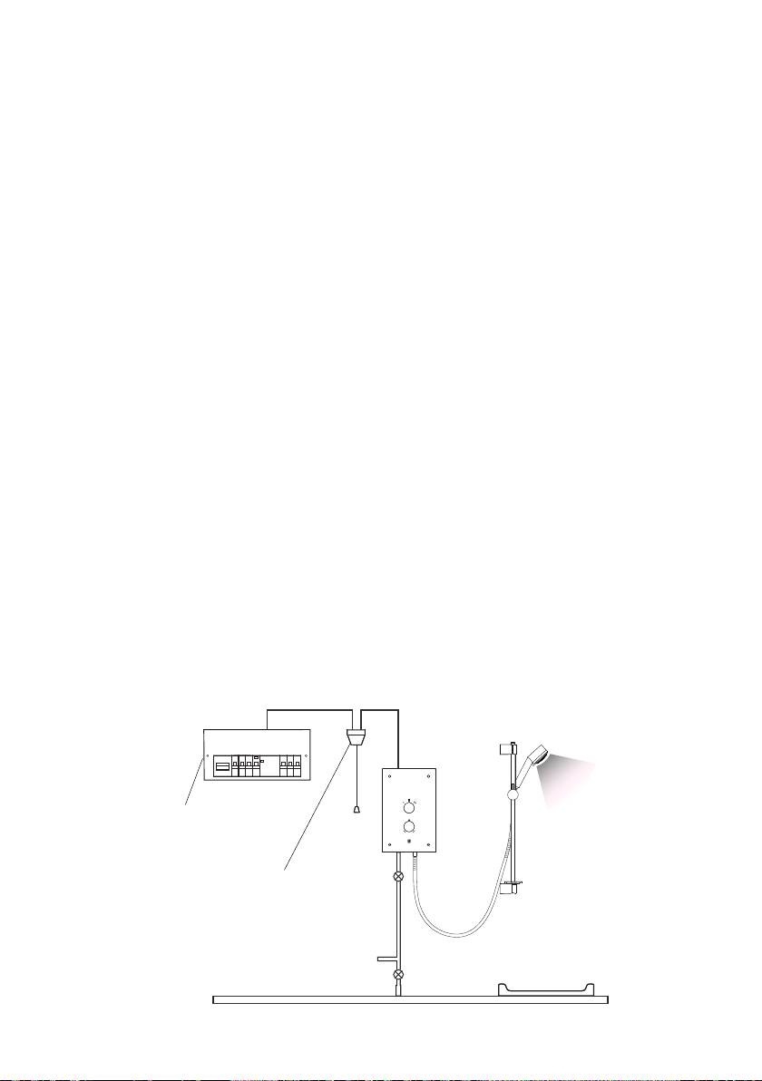
Consumer Unit
Double-pole
Isolating Switch
Plumbing and Electrical Schematic
9
 Loading...