

Page 1
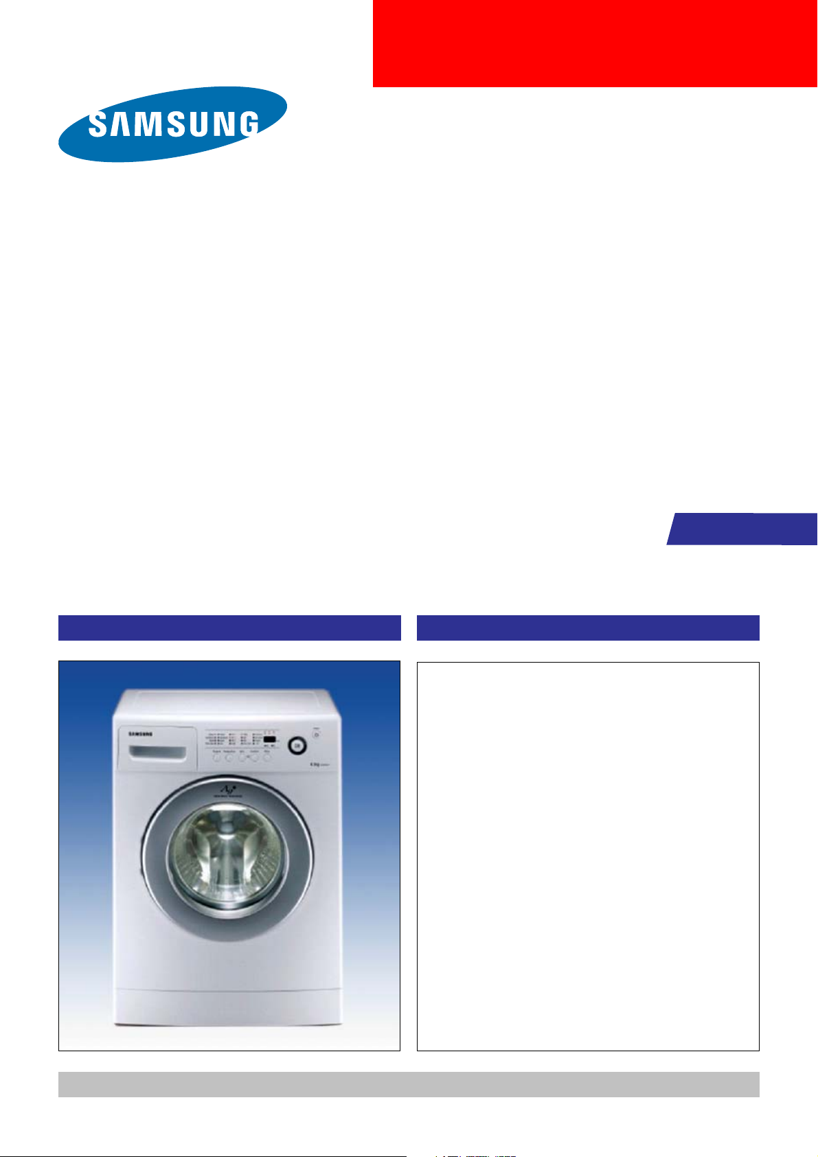
WASHING MACHINE
DRUM TYPE
BASIC : WF-F1061
MODEL NAME : WF7450SAV
WF7450NAW
MODEL CODE : WF7450SAV/YLP
WF7450SAV/YLR
WF7450SAV/YLW
WF7450NAW/YLW
WF7450NAW/YLR
SERVICE
PRODUCT IMAGE THE FEATURE OF PRODUCT
1. QUICK WASH
2. DELAY START
3. HAND WASH
4. SILVER NANO(OPTION)
5. CERAMIC HEATER(OPTION)
Manual
Refer to the service manual in the itself (http://itself.sec.samsung.co.kr/) for the more information.
Page 2

CONTENTS
1. PRECAUTIONS
1-1. SAFE PRECAUTIONS .......................................................................................................................................... 1
1-2. PRECAUTIONS UPON INSTALLATION ................................................................................................................ 2
2. THE FEATURE OF PRODUCT
2-1. SPECIFICATIONS .................................................................................................................................................. 5
2-2. OVERVIEW OF THE WASHING MACHINE .......................................................................................................... 6
2-3. THE COMPARATIVE SPECIFICATIONS OF PRODUCT ...................................................................................... 7
2-4. ACCESSORY AND OPTION SPECIFICATIONS ................................................................................................... 8
3. PRODUCT SPECIFICATIONS
3-1. OVERVIEW OF THE CONTROL PANEL ............................................................................................................... 9
3-2. PROGRAMME CHART ........................................................................................................................................ 10
3-3. MAIN FUNCTION .................................................................................................................................................12
3-4. TECHNICAL POINT ............................................................................................................................................. 15
3-5. DESIGNATION OF MAIN COMPONENTS .......................................................................................................... 18
4. ALIGNMENT AND ADJUSTMENTS
4-1. GENERAL ERROR FUNCTION ........................................................................................................................... 20
4-2. TEST MODE ......................................................................................................................................................... 22
5. ASSEMBLY AND DISASSEMBLY
5-1. TOOLS FOR DISASSEMBLY AND ASSEMBLY ..................................................................................................23
5-2. ASSEMBLY AND DISASSEMBLY ........................................................................................................................ 24
6. TROUBLE DIAGNOSIS
6-1. TROUBLE DIAGNOSIS ........................................................................................................................................ 33
6-2. PROBLEM CHECKING AND METHOD OF PCB ................................................................................................. 35
6-3. DETAILED DIAGNOSIS .......................................................................................................................................41
7. EXPLODED VIEWS AND PARTS LIST
7-1. EXPLODED VIEWS OF TOP(FRONT) ................................................................................................................ 42
7-2. EXPLODED VIEWS OF TUB ............................................................................................................................... 43
7-3. EXPLODED VIEWS OF CASE ............................................................................................................................ 44
7-4. PARTS LIST .........................................................................................................................................................45
Page 3

CONTENTS
8. BLOCK DIAGRAM ...................................................................................................................................48
9. WIRING DIAGRAM
9-1. PCB ASSY’ LAYOUT ............................................................................................................................................ 49
9-2.CONNECTOR & RELAY TERMINALS DESCRIPTION (MAIN PCB) .................................................................... 50
9-3.CONNECTOR & RELAY TERMINALS DESCRIPTION (AG-KIT PBA OPTION) ................................................. 51
10. SCHEMATIC-DIAGRAM
10-1. ROLD (WF7450SAV) .......................................................................................................................................... 52
11. PCB CIRCUIT DIAGRAM
11-1. PCB CIRCUIT DIAGRAM ................................................................................................................................... 53
11-2. PCB CIRCUIT DIAGRAM (AG-KIT OPTION) .................................................................................................... 54
12. CIRCUIT DESCRIPTION
12-1. OVERALL SYSTEM ........................................................................................................................................... 55
12-2. AC INPUT & POWER CIRCUIT ......................................................................................................................... 56
12-3. DRIVING SYSTEM CIRCUIT ............................................................................................................................ 57
12-4. MOTOR CIRCUIT .............................................................................................................................................. 58
12-5. SENSOR DETECTION CIRCUIT ...................................................................................................................... 59
12-6. MOTOR TACHO INPUT SYSTEM .................................................................................................................... 60
12-7. SILVER NANO SYSTEM (OPTION) .................................................................................................................. 61
13. REFERENCE INFORMATION
13-1. MODEL NAME ................................................................................................................................................... 62
13-2. TERMINOLOGY ................................................................................................................................................. 63
13-3. FABRIC CARE CHART ......................................................................................................................................64
13-4. ELECTRICAL WARNINGS ................................................................................................................................. 64
13-5. Q & A ..................................................................................................................................................................65
Page 4
1. Precautions
1-1. Safe Precautions
1. Do not allow the customer to repair the product.
It may cause personal injury or product damage when the unit is serviced by unqualifi ed personnel.
2. Disconnect power to the appliance before servicing.
Be aware of the possibilities of an electric shock.
3. Do not use multi-plug.
Power outlet may be overloaded causing the socket to overheat.
4. Check for any damage on power plug or power outlet.
Replace it immediately if it has problem. (It may cause an electric shock or fi re)
5. Make sure to earth the product.
May cause electric shock.
6. Do not clean the product with water.
May cause electric shock / fi re or shorten product life.
7. The wiring harness should be free from moisture and connected properly during serving.
It should be proof against any external force.
8. Remove any dust or dirt in the product, wiring section and connections during servicing.
Protect against possibilities of fi re due to tracking etc.
9. Check for any water trace on electrical parts, harness, etc.
Replace the parts or wipe dry the water.
10.Check the assembled status of the parts after servicing.
Check if the product is assembled in the same status as before servicing.
11.Be sure not to pull on the power cord but to unplug it by holding the plug.
Beware of possibility of electric shock or fi re when the power cord is damaged.
12.Unplug the power plug from the outlet when the washing machine is not used.
Beware of possibility of electric shock or fi re while lightening.
13.Do not use or put fl ammable materials (including gasoline, alcohol, thinner etc) around the
washing machine.
Flammable materials may spark an explosion or fi re.
14.Do not put a water containing bowl or wet laundry on the washing machine.
It may cause an electric shock or fi re, or shorten the product life when its water penetrates into the
washing machine.
15.Do not install the washing machine in a place where it is exposed to snow or rain etc.
It may cause an electric shock or fi re and shorten the product life.
16.Do not press control buttons with pointed objects such as pins, needles, etc.
It may cause an electric shock or other problems.
17.Check the washing machine is leveled horizontally on the fl oor and is installed properly.
Vibration may shorten the product life.
18.Make sure to use connectors when connecting wires.
If wires are connected without connectors, it may cause a tracking fi re.
19.When the washing machine is to be laid down for servicing, put a pad on the fl oor and lay the product
on its side slowly.
If the wash machine is laid on its front, internal components may be damaged by the tub.
1
Page 5

1-2. Precautions upon Installation
■ How to Remove Shipping Bolts
■ Precautions before Installation
1. Remove the screws by using
the supplied spanner.
3. Fill the holes with the
supplied plastic caps.
2. Remove the shipping bolts
from the back of the unit.
4. Keep the shipping bolts and
screws for future use.
The unit is quite heavy. So,
make sure to have 2 or more
personnel move it.
Install the unit at a place with
a wall outlet easily accessible.
Make sure that the unit stands
on a fi rm and leveled fl oor.
Keep the unit away from places in
which it is freezing, especially in
winter.
2
keep it away from direct sunlight
or high humidity, and install it in
a place with good ventilation.
Keep the unit away from heat
appliances such as a heater.
Page 6
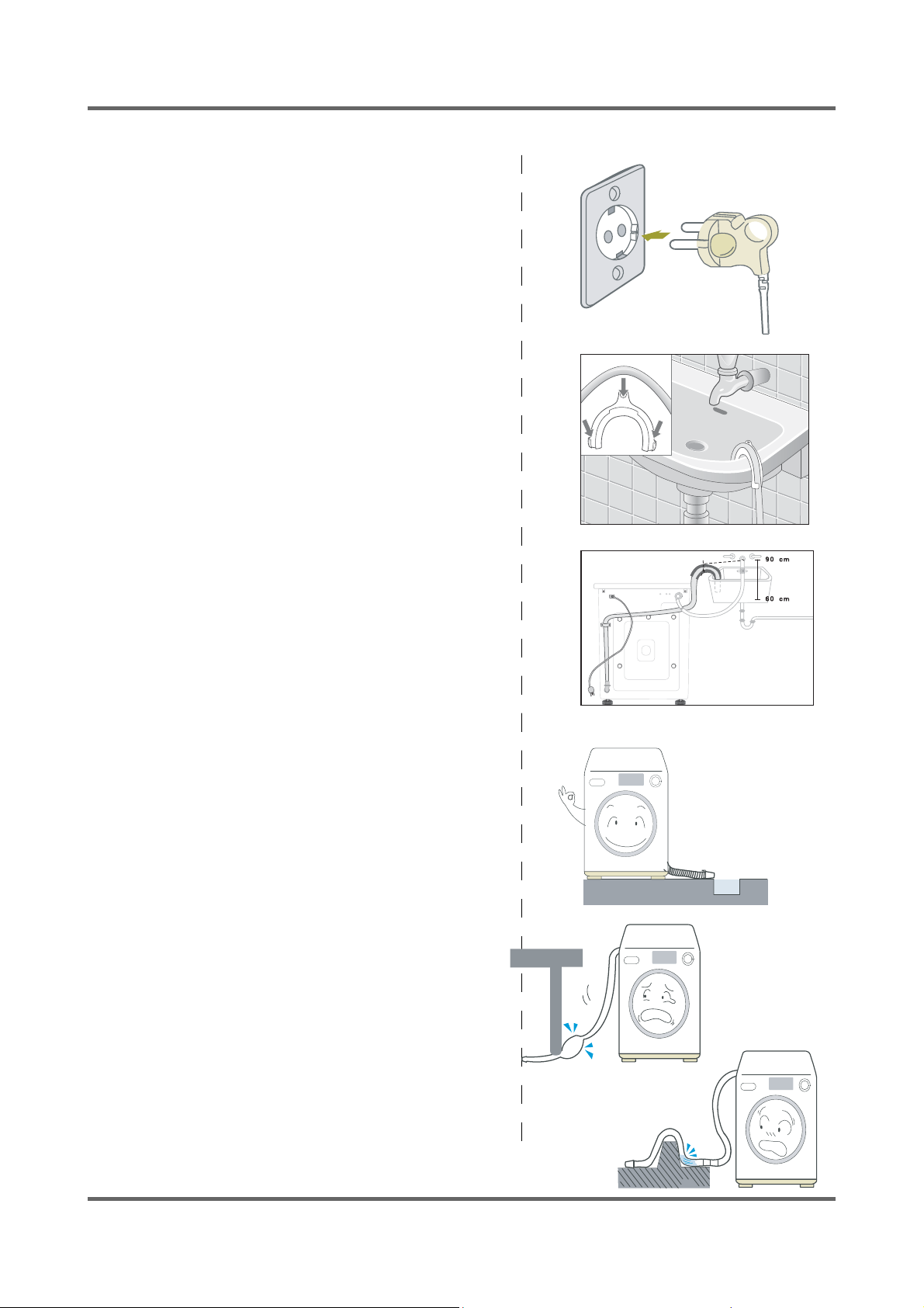
■ Grounding
Ć Make sure to ground the unit to prevent electric leak-
age or shock.
Ć With a grounded receptacle
It does not need an additional grounding.
■ Water Drainage
Ć Hook the drain hose over the Wash Basin or Laundry
Tub or plug the end of the drain hose into the Standpipe.
- Hook the drain hose over the Wash Basin or
Laundry Tub or plug the end of the drain hose
into the Standpipe.
- The outlet end of the drain hose must be at
least 60-90 cm above the base of the machine.
Ć Seal the drain pipe connections.
- If not, it may cause water leakage.
Ć Prevent water from siphoning away.
- If the end of the drain hose is put in water,
it could siphon away water during washing.
So, make sure that the end of the drain hose
is not put in water.
Note: Caution must always be exercised to
avoid collapsing or damaging the drain hose.
For best performance the drain hose should
not be restricted in any way, through elbows,
couplings or excessive lengths.
3
Page 7
Ca
utionon
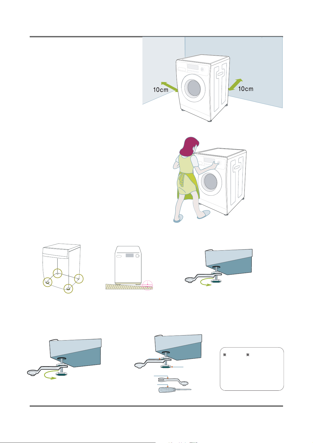
■ How to Level the Unit
1.Select an installation place.
Install the unit with 10cm or more
clearance from its surrounding walls.
2.Check if the unit is leveled.
If the unit wabbles, adjust the leveling
legs.
3.Adjust the leveling legs.
The 4 leveling legs should touch the
fl oor all together.
After adjusting the leveling bolt, tighten the
lock nut by turning it clockwise.
When the unit is not leveled
Lift up the unit a little bit and adjust the shortest.
Turn the leveling bolt counter clockwise as shown in the picture above
(The leveling leg gets longer.)
Lock Nut
Leveling Bolt
Spanner
Flat Head
Screwdriver
uti
Tighten the lock nut after
the leveling. If not, it
could generate vibrations &
noises.
4
Page 8
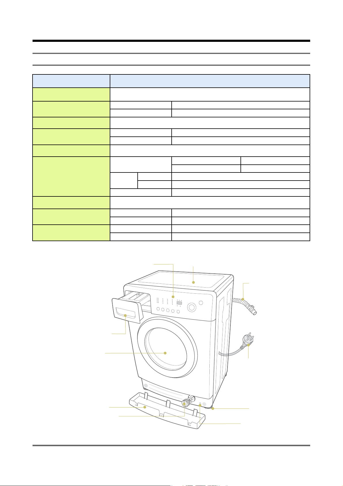
2. THE FEATURE OF PRODUCT
2-1. SPECIFICATIONS
WASH TYPE FRONT LOADING TYPE
MODEL NAME WF7450SAV,WF7450NAW
DIMENSION
WATER PRESSURE 50 kPa ~ 800 kPa
WEIGHT
WASH and SPIN CAPACITY 4.5 kg (DRY LAUNDRY)
WASHING
AND HEATING
SPIN
PUMPING 34 W
WATER CONSUMPTION 43ℓ(STANDARD COURSE)
SPIN REVOLUTION
PACKAGE Wt
MODEL WF7450SAV,WF7450NAW
rpm 1000
PAPER 2.5kg
PLASTIC 1.0kg
PANEL CONTROL
NET W 598mm X D 400mm X H 844mm
GROSS W 668mm X D 530mm X H 890mm
NET 55 kg
GROSS 58 kg
220V 1900W
240V 2200W
MODEL WF7450SAV,WF7450NAW
220~240V 230W
COVER TOP
DRAWER
DOOR GLASS
BASE COVER
DEBRIS FILTER
DRAIN HOSE
POWER PLUG
ADJUSTABLE LEG
EMERGENCY DRAIN TUB
5
Page 9
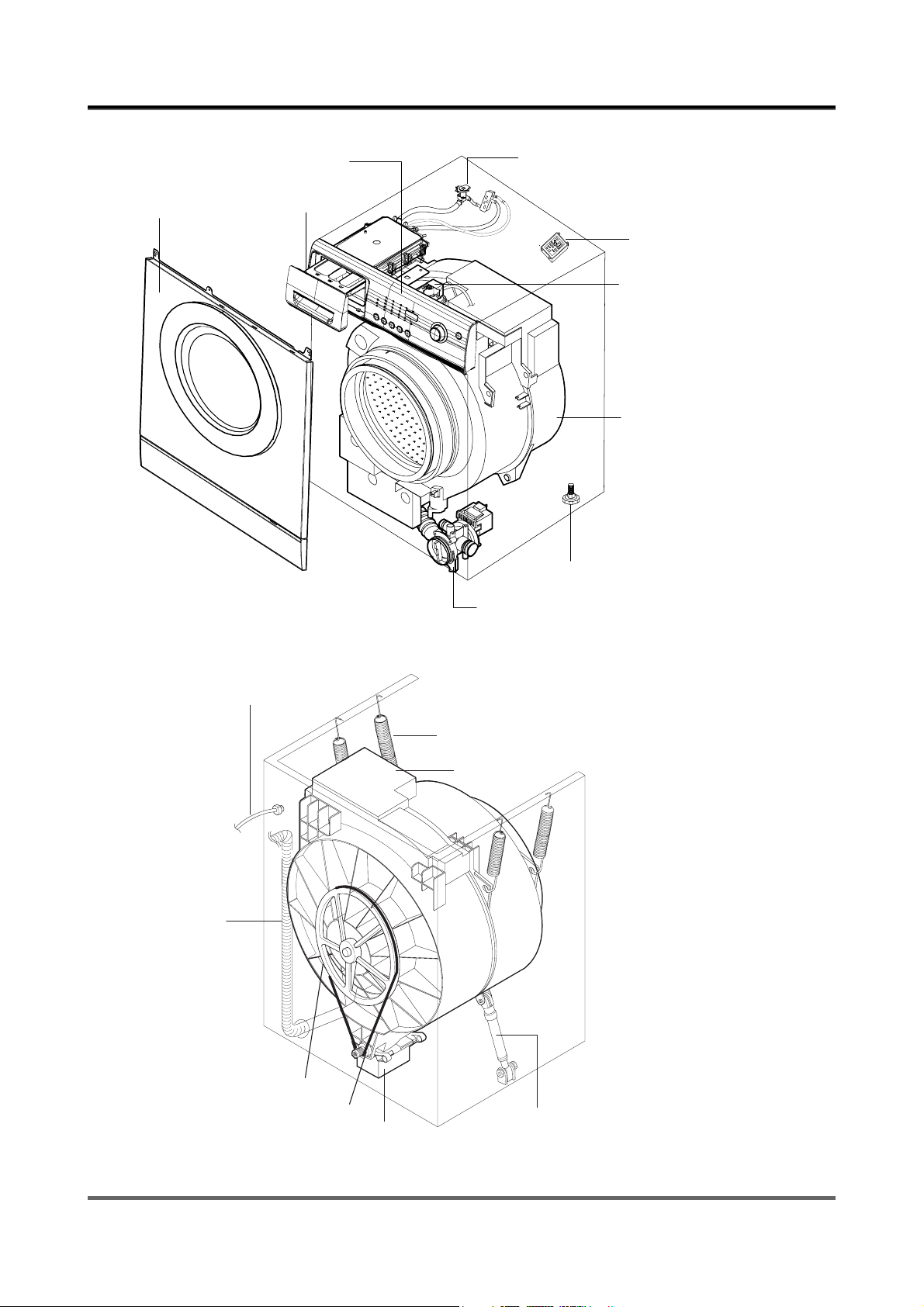
2-2. OVERVIEW OF THE WASHING MACHINE
A
CONTROL PANEL
SSY-DOOR
DRAWER
WATER SUPPLY VALVE
AG-KIT PCB
SENSOR PRESSURE
TUB
ADJUSTABLE LEG
DRAIN HOSE
ASSY PUMP
POWER CORD
BUFFER SPRING
WEIGHT-BALANCE
PULLEY
BELT
MOTOR
SHOCK ABSORBER
6
Page 10
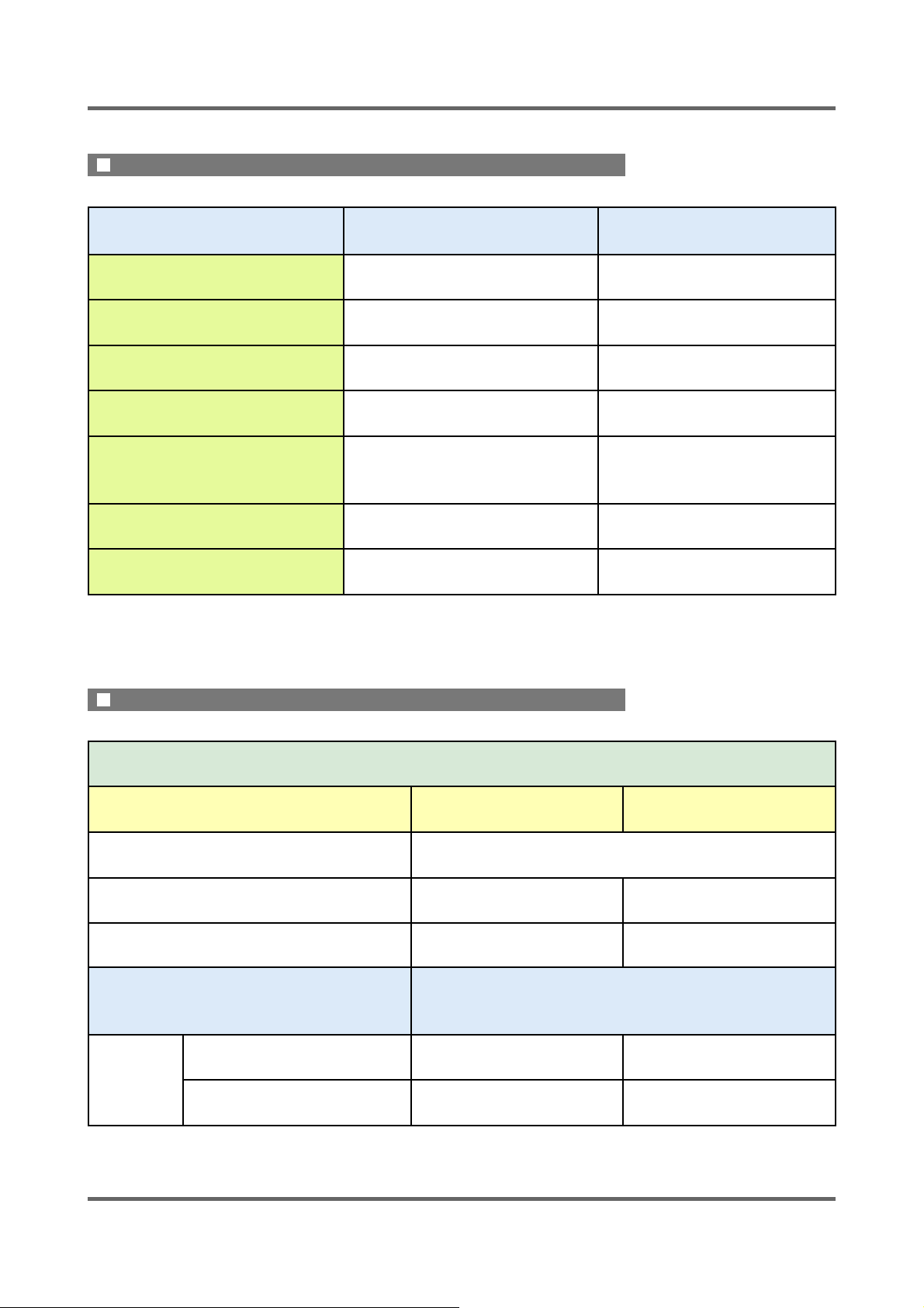
2-3. THE COMPARATIVE SPECIFICATIONS OF PRODUCT
THE COMPARATIVE SPECIFICATIONS OF PRODUCT˄ϔ˅
Item 4.5kg Old (4.5kg)
Model Name WF7450SAV WF-F1061
Capacity (Washing) 4.5kg 4.5kg
Drum Capacity 43ℓ 43ℓ
Washing Motor HXGP2I HXGP2I
Supply/Drain All temperatures /Drain pump Cold /Drain pump
Balancer Weight Weight
SIZE(W*D*H) 598*400*844 598*400*844
THE COMPARATIVE SPECIFICATIONS OF PRODUCT˄Ѡ˅
4.5kg
Model Name
Water-level Control O O
Add Laundry X X
Exterior Replacement
Part Name
WF7450SAV WF7450NAW
Function
Specifi cations
Design
Cover Door
FRAME FRONT
SILVER WHITE
SILVER WHITE
7
Page 11
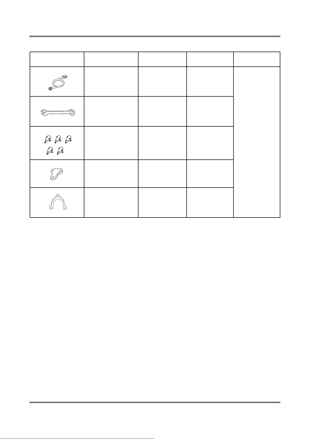
2-4. ACCESSORY AND OPTION SPECIFICATIONS
ITEM DESCRIPTION CODE-NO. Q’TY REMARK
HOSE-WATER(C) DC62-10289C 1
BOLT-SPANER DC60-40146A 1
CAP-FIXER DC61-10688A 5
CAP-FIXER DC67-00208A 1
HOSE-HANGER DC62-10278A 1
8
Page 12
3. PRODUCT SPECIFICATIONS
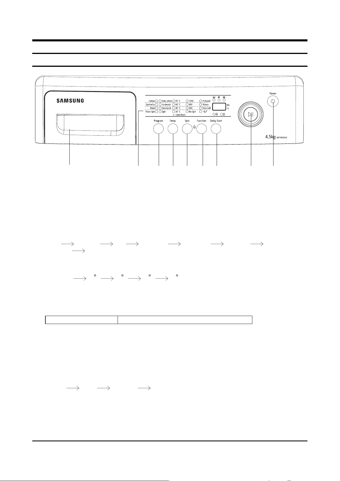
3-1. OVERVIEW OF THE CONTROL PANEL
ķǂǂǂǂǂǂǂǂǂĸǂĹǂĺǂĻǂǂļǂĽǂľǂǂĿ
1. Detergent dispenser
2. Display panel
Displays wash cycle and error messages.
During execution of the program, the program indicator blinks.
3. Program selection button
Press the button repeatedly to select one of the eight available wash button.
Cotton Synthetics Wool Rinse+Spin Baby cotton Handwash
Quickwash Spin.
4. Temperature selection button
Press the button repeatedly to cycle through the available water temperature options.
(Cold water 30 C 40 C 60 C 95 C).
When pressing this button during washing, you can see the selected temperature in the diaplay panel.
5. Spin selection button
Press the button repeatedly to cycle through the available water temperature options.
WF7450SAV,WF7450NAW Rinse hold,No spin,400,800,1000rpm
No spin
The laundry remains in the drum without being spin after the fi nal drain.
Rinse hold
The laundry remains soaking in the fi nal rinse water.
Before the laundry can be unloaded, either “Drain” or the “Spin” program must be run.
6. Function selection button
Press the button repeatedly to cycle through the available partial wash options.
Prewash Rinse+ Rinse Hold Ag+.
7. Delay start selection button
Press the button repeatedly to rotate between the retarded start options avaiable.
(from 3 hours to 24 hours, in 1 hour increments.)
9
Page 13

3-1. OVERVIEW OF THE CONTROL PANEL
8. Start/Pause selection button
Press to pause and restart programs.
Press the start/pause button before adding laundry.
This can only be selected within 5 minutes of the start.
9. On/Off button
Press once to turn the washing machine on, press again to turn the washing machine off.
If the washing machine power is left on for longer than 10 minutes without any buttons being touched,
The power automatically turns off.
What is the “Child Lock” function
-If you press the “Child Lock” button (rinse+spin) longer than 2 sec during operation, this function is
selected.
-If once this function is selected, no change can be done until the end of laundry.
-Press the “Child Lock” button (rinse+spin) longer than 2 sec to cancel the function.
Note: Check out the Child Lock button fi rst when no button is activate while the washing machine
is working.
10
Page 14
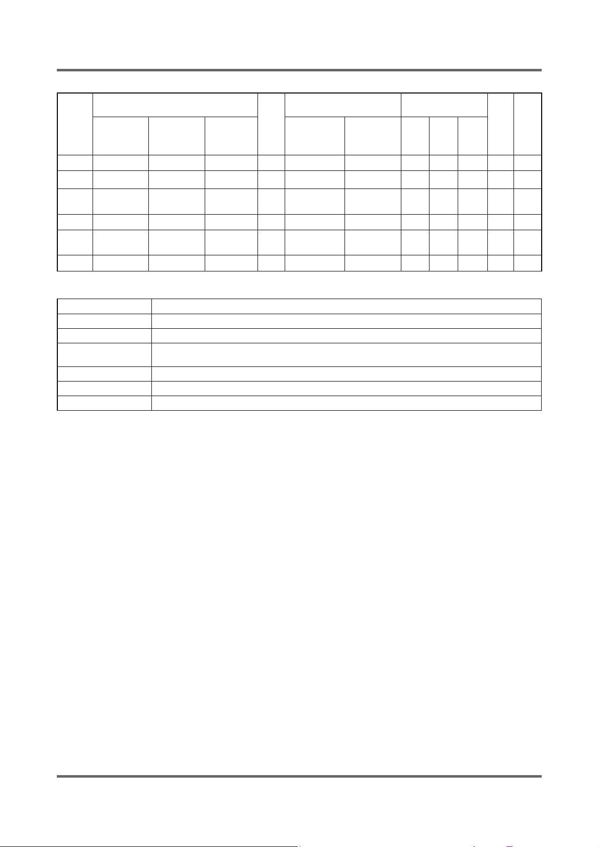
3-2. PROGRAMME CHART
PROGRAM
Cotton
Colour
Syn-
thetics
Wool
Hand-
wash
Quick
PROGRAM
Cotton
Colour
Synthetics
Wool
Handwash
Quick
Max load
(kg)
WF7602SAV
WF7600NAW
6.0 5.2 4.5 95 1200 1000
6.0 5.2 4.5 60 1200 1000
3.0 2.5 2.5 60 800 800
2.0 1.5 1.5 40 400 400 - √
2.0 1.5 1.5 40 400 400 - √
3.0 2.0 2.0 60 1200 1000 - √
WF7520SAV
Averagely or lightly soiled cottons, bed linen, table linen, underwear, towels, shirts, etc.
Averagely or lightly soiled cottons, bed linen, table linen, underwear, towels, shirts, etc.
Averagely or lightly soiled blouses, shirts, etc., Made of polyester(diolen, trevira), polyamide (perlon, nylon)
or other similar blends.
Only machine washable woolens with pure new wool label.
Very light wash couse like hand wash.
Lightly solied cottons or linen blouses, shirts, dark coloured terry cloth, colourd linen articles, jeans, etc.
WF7450SAV
WF7450NAW
Max
temp
(ć)
Spin Speed
(MAX)rpm
WF7602SAV
Type of WASH
WF7600NAW
WF7520SAV
WF7450SAV
WF7450NAW
wash
Detergent
And additives
Pre
wash
γ
γ
γ
ender
√
√
√
De-
soft-
lay
start
γγ
γγ
γγ
γγ
γγ
γγ
Cycle
Time
(min)
126
98
73
42
37
28
1. Programme with prewash lasts approx. 15 minutes longer.
2. The programme duration data has been measured under the conditions specifi ed in
Standard IEC 456.
3. Consumption in individual homes may differ from the values given in the table due to
variations in the pressure and temperature of the water supply, the load and the type of
laundry.
11
Page 15
3-3. MAIN FUNCTION
1) Auto power S/W off function
● After power on, the auto power S/W off function automatically switches power off for you if you do not
press selection button for 10 minutes.
● After selecting the function, the auto power S/W off function automatically switches power off for you if
you do not press start/pause button for 10 minutes.
● until 5 minutes past, After fi nishing the last function, the auto power S/W off function automatically
switches power off for you if you do not re-select the course button or manual button.
2) Door open function
● Door just can be opened at water level 24.05 KHz over, water temperature 55ć below, motor off, if
power is off door is not opened (only auto-door model).
● If door is open during the operating, all operating is halted, and door error message will be displayed
(2-digit panel displays “dE” 4-digit panel displays “door”) and error melody will coming out .
● Door open error can be cleared by closing the door. the operating keeps going on.
3) Rinse hold function
● If rinse hold function selected, the operating is fi nished , the machine do not drain the water after last
rinse.
4) No spin function
● If no spin function selected, the operating is fi nished after last rinse.
5) Drain function
● Drain function is over, after pumping out the water for 2 minutes , without motor rotating.
6) Pre-washing function
● Pre-washing function can be selected ,when you choice the following mode; cotton, coloreds, syn.
thetics, delicates, baby cotton, baby coloreds, baby delicates, baby stains.
● Water level/reverse time is the same with the selected course.
● Pre-washing takes about 16 minutes.
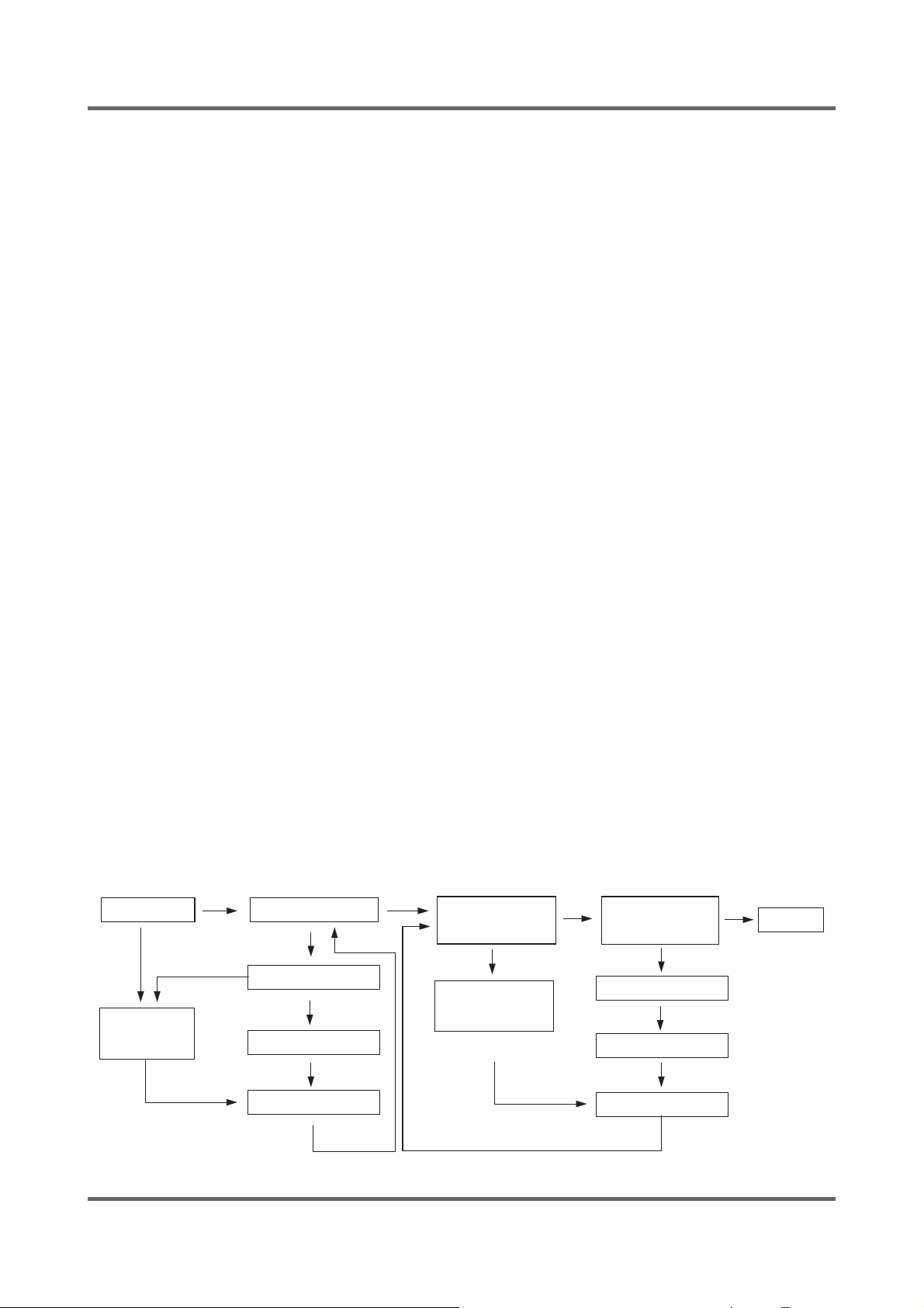
7) Power-out compensation function
● If power is out on selected process, the process before power out is stored to EEPROM, once power is
back the process before power out continues.
● When power is back, washing process starts from the process at the point of the power out, rinse/drain
process starts from the initial process.
POWER-OUT COMPENSATION FUNCTION PROCESS
START WASHING
POWER OUT
SAVE DATA
to EEPROM
POWER BACK
MICOM RESTORE
RINSE/DRAIN
START
SAVE DATA
to EEPROM
RINSE/DRAIN
PROCESS
POWER OUT
POWER BACK
MICOM RESTORE
FINISH
12
Page 16
8) Fuzzy washing function (weight-sensing)
● After fi nishing initial water supply, when the fall of the water level needs supplementary water supply,
Sensing function perceives the weight with the supplementary water supply numbers and starts to
work. Under the course of Cotton, or Coloureds, if the supplementary water supply numbers become
over 2 times the function is going at default condition ( high water level ), if 1 time that is going at
middle level, if 0 below low water level, heating hours and rinse hours depend on the above data.
ECO PRE mode is selected, the process going on at default condition.
Washing hours
Cotton Coloureds
Rinse water level
High Default Default Default
Middle Default-20 min Default-10min 23.80KHZ
Low Default-30 min Default-15min 24.10KHZ
ĆAfter sensing weight, above hours is decreased from above default hours
9) Bubble - detecting function
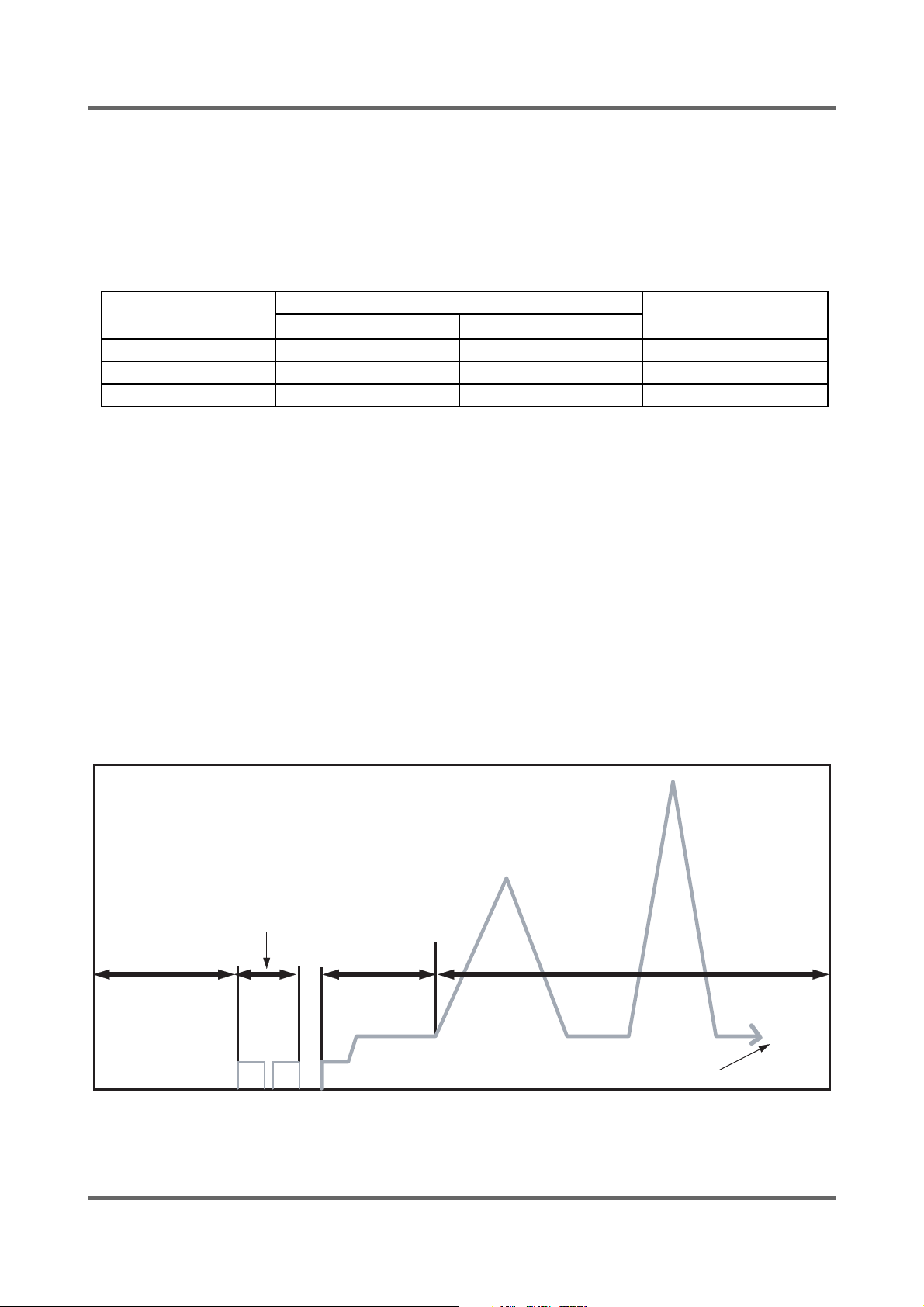
At the each condition of washing&dehydrating , rinse&dehydrating , hydrating, bubble -detecting function
works, this function works 5times normally, if the function detects bubbles at 6 times , the bubble-detecting function
stops and go on to the next process.
● The bubble-detecting function during washing & dehydrating to rinse & dehydrating
after 2 times instant dehydrating and before main dehydrating, if the water level is under 24.50KHZ,
Bubble
→ Detecting function thinks there are bubbles and add the bubbles-removing rinse, needing
hours are above hours and 8 Min 40 sec.
→ The bubble-detecting function during single hydrating process
after 2 times instant dehydrating and before main dehydrating , if the water level is 24.50KHZ below or
during main dehydrating, water level data is 24.50KHZ below Bubble-detecting function thinks there are
bubbles and add the bubbles-removing rinse 1 times, needing hours are above hours and 5 min 50 sec.
Bubble-detecting function operating process
18 sec
laundry scattering
draining &reverse
50 sec
unbalance
detecting range
500rpm
220rpm
bubble detection
(default water level 24.50KHZ below)
13
Page 17
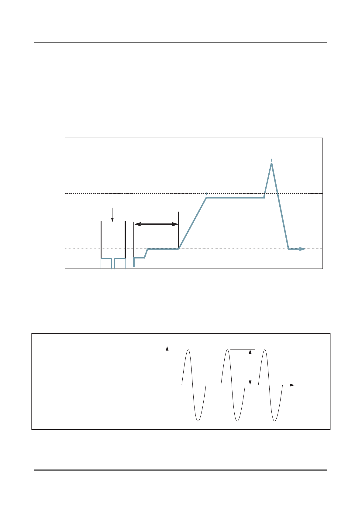
10) Unbalance detecting & laundry balance positioning system
ķ Just before the hydrating process and just after reversal rotation for balancing laundry position, this
function is carried out
ĸThe initial 6 sec is the period of reversal rotation for balancing laundry position , Drum rotates 50rpm
for initial 6 sec
Ĺ Next 12 sec, the rotation increases the speed from 50 rpm to 95 rpm slowly
ĺ During the next 8 sec, drum rotates at the speed of 95 rpm, the sensor decides the degree of laundry
unbalance with TACHO data which is attached to motor
Ļ If the degree of unbalanced laundry is over 6 times to default value, laundry balancing system carryies
out feed back process 3 times.
Unbalance detecting & laundry balance positioning system
410rpm
500rpm
220rpm
220rpm
9sec
laundry scattering
unbalance
detecting range
95rpm
11) R.P.M control
The rotating motor enables the magnetics( i.e generator) to generate magnetic fl ux in proportion to
r.p.m, magnetic fl ux induced by coil sensor in the opposite side produces the wave like the fi gure below
to dΦ/dt and via rectangular wave generating circuit, the waves reaches MICOM and micom controls
r.p.m with the pulse, count and cycle inputted by program.
<COIL electrical wave at both ends>
V (VOLT)
Vp
T (HOUR)
14
Page 18

3-4. TECHNICAL POINT
1) Motor on/off time at each course
unit:sec
Course
Cotton 13 4 13 4 50
Coloureds 12 8 12 8 50
Synthetics 10 5 10 5 50
Delicates 5 10 5 10 50
Wool 2 48 2 48 50
Handwash 258258 50
Quick 22 4 22 4 50
Bed Linen 10 10 10 10 50
Heavy Soil 12 8 12 8 50
Baby Cotton 12 8 12 8 50
Daily Wash 12 8 12 8 50
Model
Cw Off Ccw Off
Washing
Motor r.p.m
2) Final dehydrating r.p.m at each course
Model
Course
Cotton 1000
Colour 1000
Synthetics 800
Wool 400
Handwash 400
Quick 1000
Ć You can change the r.p.m to the above a table by use spin button under no spin situation.
WF7450SAV,WF7450NAW
unit:rpm
15
Page 19
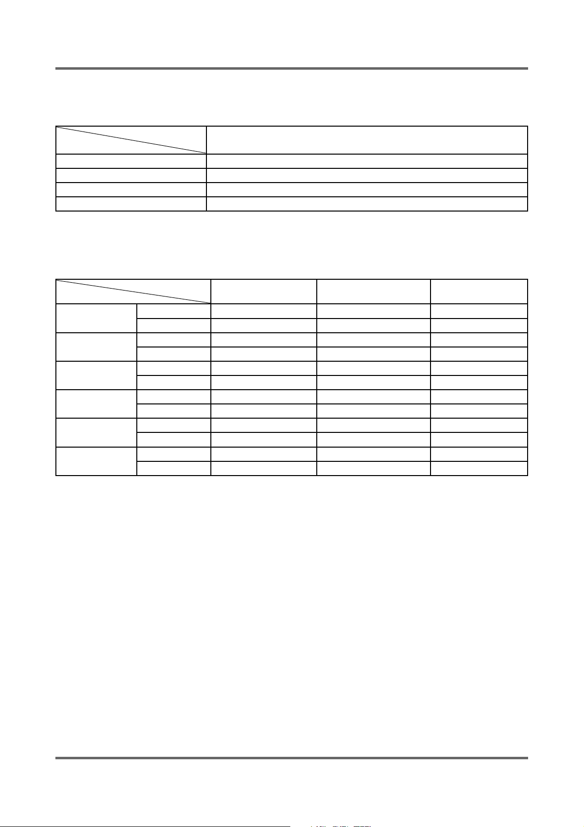
3) The water supply control at each process cycle
Model
Process cycle
Pre Washing Cold water 5L/min
Washing Cold water 10L/min + (Hot water 10L/min)
Rinse Cold water 10L/min
Final rinse Cold water 10L/min + Cold water 5L/min
WF7450SAV,WF7450NAW
4) The water level data at each course
Course
Cotton
Colour
Synthetics
Wool
Handwash
Quick
Model
Washing 23.80 24.30 24.10
Rinse 23.20 24.20 24.00
Washing 23.80 24.30 24.10
Rinse 23.20 24.20 24.00
Washing 23.00 24.00 23.70
Rinse 22.80 24.20 23.90
Washing 22.80 24.00 23.80
Rinse 22.30 23.80 23.35
Washing 22.80 24.00 23.80
Rinse 22.30 23.80 23.35
Washing 23.80 24.30 24.10
Rinse 23.20 24.20 24.00
Default water level
(kHz)
Supplementary water
START (kHz)
unit:Khz
Supplementary water
End (kHz)
16
Page 20
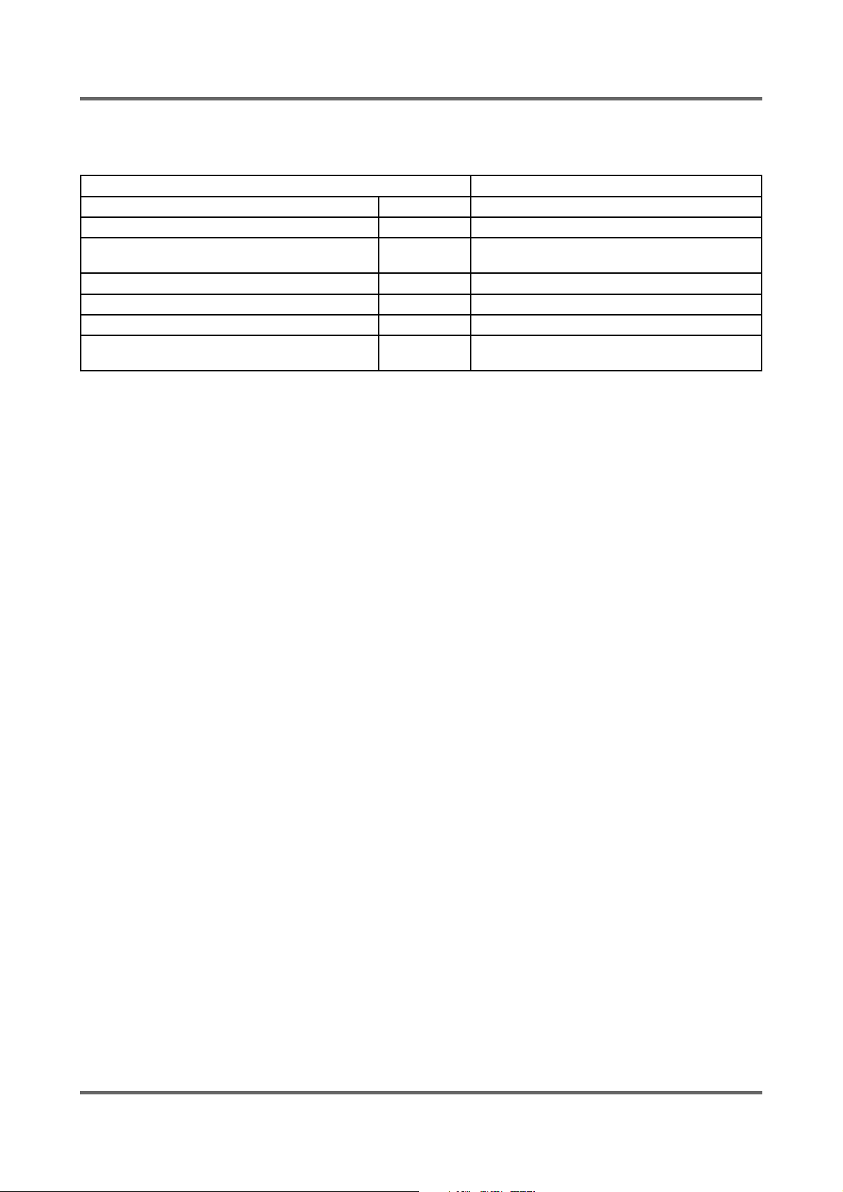
5) The other water level data
The water data unter each conditon
1st water supply (only preparation) 24.80 1st water supply level to washing tub
Overfl ow error 21.00 The water supplied reach 2/3 of door
Bubble
detectingatwashing/rinse/dehydrating
Bubble detecting rinse water level 23.50 The water level which can detect bubbles
Water level which can open door 24.80 over It is possible to open the door
Water level which can drive heater 24.80 Safety water level of wash heater
Water level which can reset the drain 24.80 The water level can be detected after 1st drain-
ĆIf water level is 15KHZ below or 30 KHZ above , Sensor-pressure is out of order so needs changing.
24.50 Bubble -detecting water level
ing
WF7450SAV,WF7450NAW
unit:Khz
17
Page 21
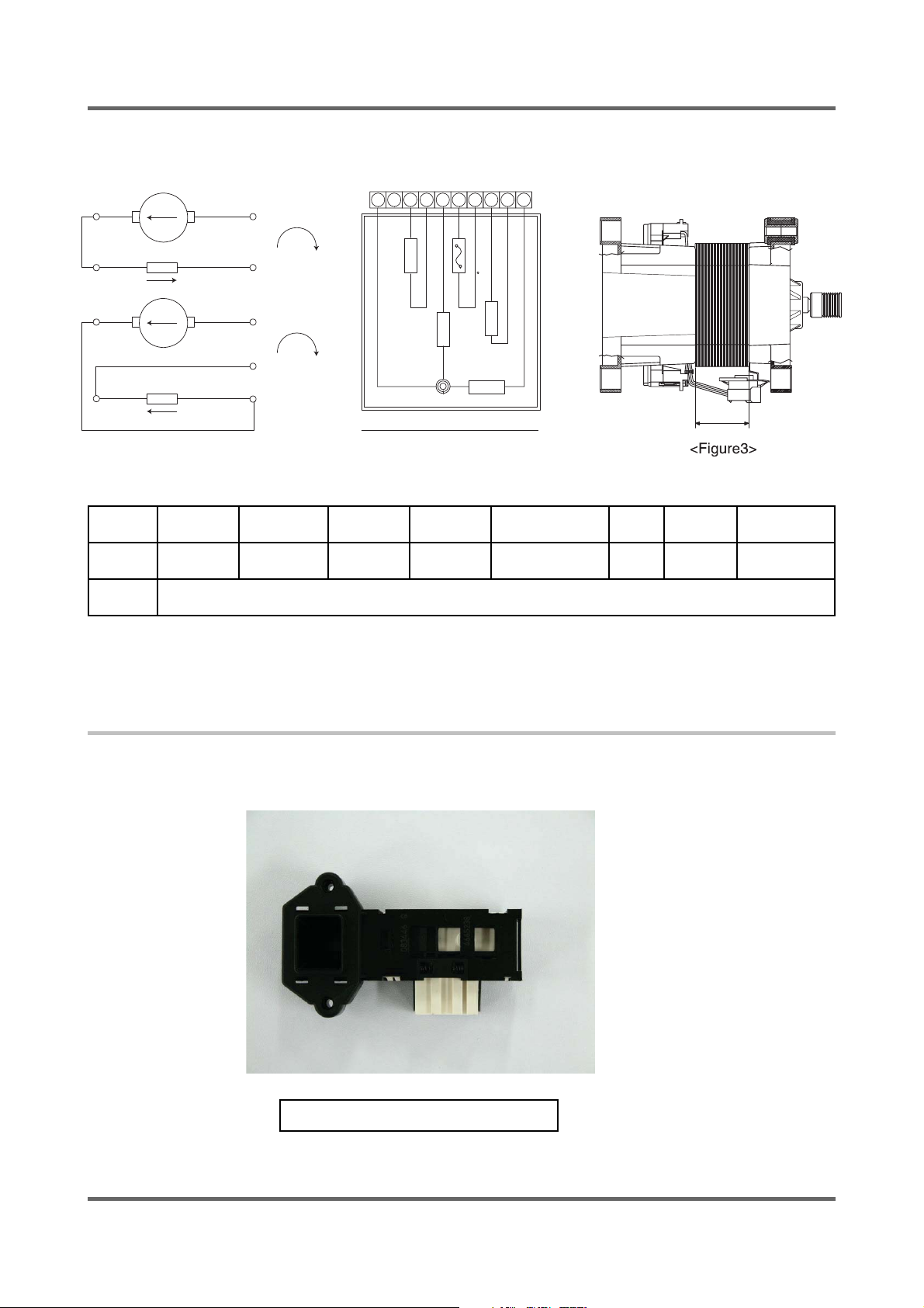
3-5. DESIGNATION OF MAIN COMPONENTS
3-5-1. Normal / Reverse Revolution of Motor and R. P. M. Control
89
Rotor
+
CW
510
89
Stator coil
Rotor
Stator coil
10
-
+
CCW
5
-
5
<Figure1> <Figure2>
(± 7%)
Resist
ancevalue
STATOR(5.1) STATOR(5.10) ROTOR(8.9) TACHO(3.4) PROTECTOR(6.7) “H”(mm) Code-No. Remark
2.07Ω 0.90Ω 2.35Ω 34.3Ω 0 30
Rated
value
123456
D
E
E
P
S
H
G
I
H
E
H
P
C
S
-
A
E
T
L
D
D
I
M
R
O
T
A
T
S
D
E
O
WASHING MOTOR
220~240V/50Hz
789
R
O
T
)
C
C
E
0
T
5
O
1
(
R
P
R
O
T
O
R
STATOR
10
DC31-
00002H
H
WF7450SAV
WF7450NAW
3-5-2. Door safety Device
When Door is closed, door stay closed. if “set” is operated, power supplied to ,wires have solenoid or bimetal keep the
door closed, and electronical power fl ows between and make it operate.
DC64-00653A (WF7450SAV)
18
Page 22
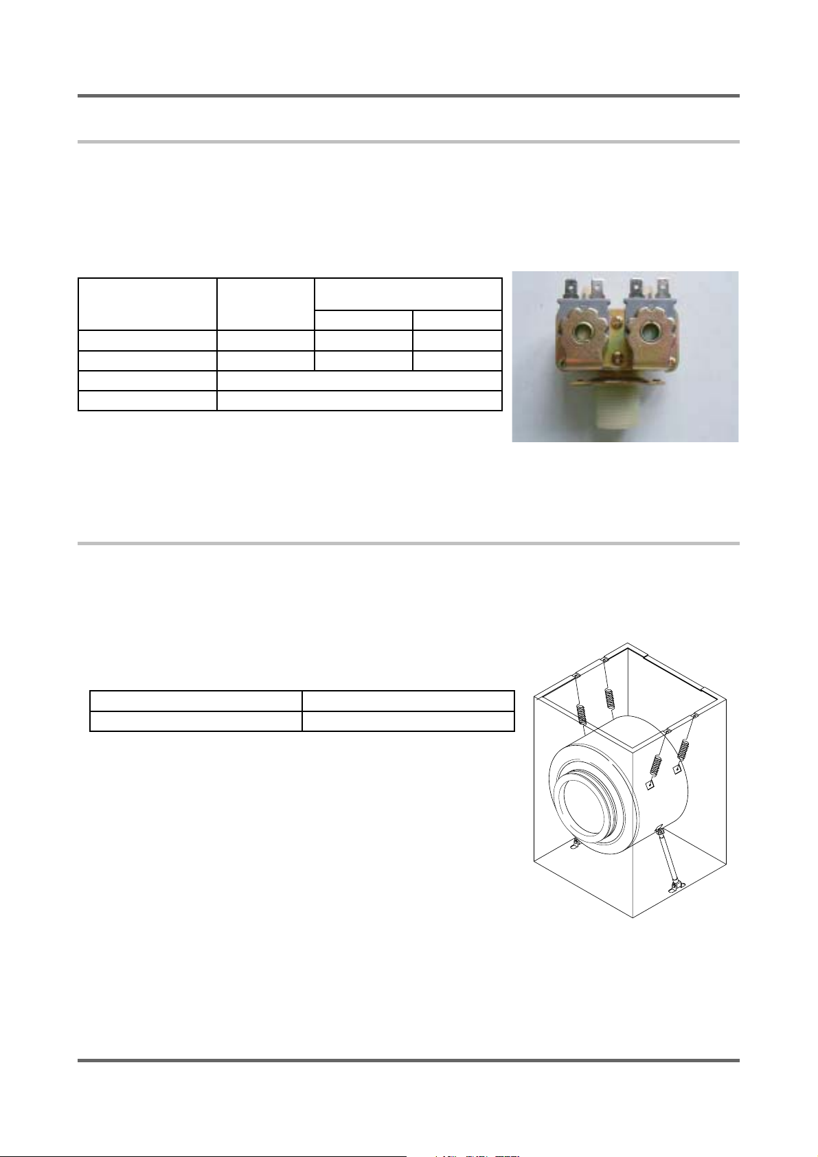
3-5-3. Detergent tub and water supply value
A Detergent tub is composed of housing and 3 drawers . supplied water fl ows into the 3 drawer-detergent
tub by way of classifi er at each washing process.
three open drainage way with detergent and supplied water by way of connector located under the housing
fl ows into washing tub.
the water supply valve is composed of a cold water valve(2way) and water
fl ow per Min in the valve is below.
Hot water
valve (1 way)
(Option)
water fl ow(L/min) 10ℓ 12 ℓ 5 ℓ
resistance value 4.4 kΩ 4.2 kΩ 4.2 kΩ
power consumption AC 220~240V 50HZ
usable water pressure 0.5 ~ 8Kg /cm3
Cold water valve (2 way)
V1 V2
3-5-4. Shock absorber and buffer spring
This wash machine is equipped with 2 Shock absorbers with same
capacity and with 2 buffer springs. 2 Shock absorber are placed
under the tub and outside case , 2 buffer springs are placed on the
right and left of the upper side of outside case.
Shock absorber function: during wash, dehydration absorb the shock.
buffer spring: buffering the vibration
device capacity of Shock absorber
Shock absorber 8±2 kg
19
Page 23
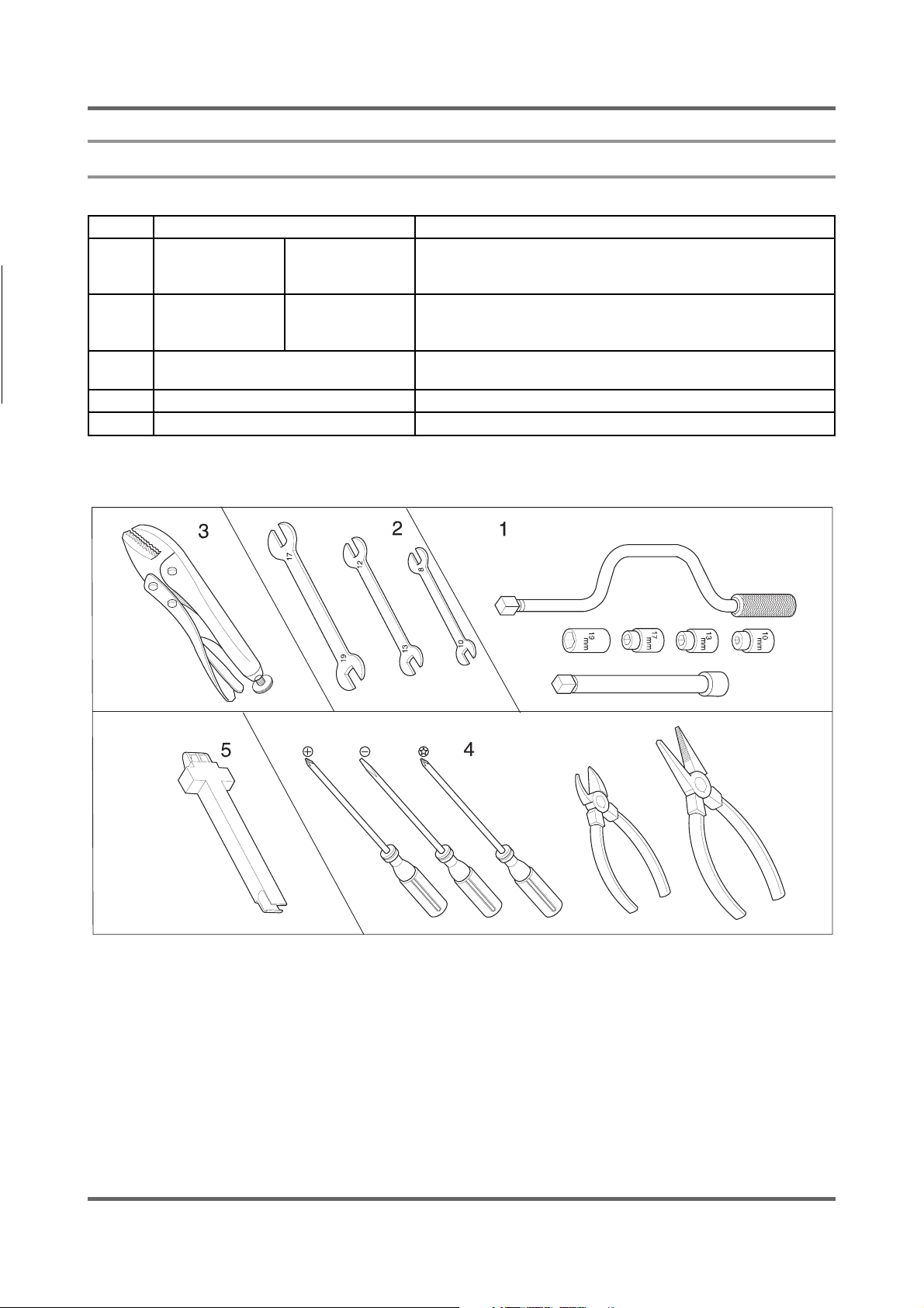
5. ASSEMBLY AND DISASSEMBLY
5-1. TOOLS FOR DISASSEMBLY AND ASSEMBLY
NO. TOOL
1
2
3 Vice pliers
4 Other(Driver, Nipper, Long nose) General tools for the after service.
5 JIG for the Tub 1 (Disassemble and Assemble)
Box driver
Double-ended
spanner
10mm
13mm
19mm
10, 13,19mm
Motor (1), Balance (5), 2 holes of each left and right of the
shock absorber 1 Pulley hole
Replaceable for the box driver.
Since the bolt runs idle when the box driver is used, use the
box driver 17mm.
Tool to protect the idle and abrasion of the bolt for the
box driver.
23
Page 24
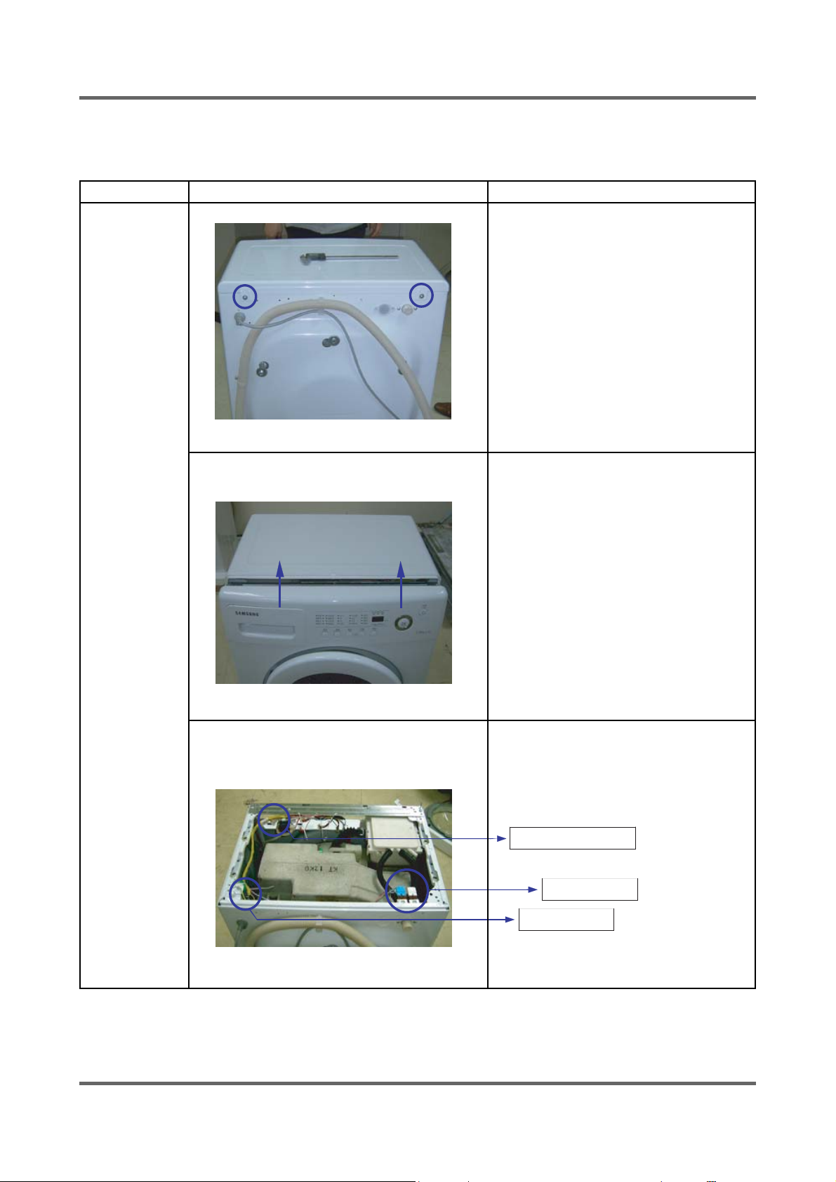
5-2. ASSEMBLY AND DISASSEMBLY
Warning! To avoid risk of electrical shock, personal injury or death, disconnect the power to the washing
machine
Part Name Descriptive Picture How To Do
ASS’Y-
COVER TOP
ķ Remove the two screws holding the
Top Cover at the back of the unit.
ĸRemove the top-cover through pushing
and pulling.
24
Ĺ Then, the Water (Pressure) Sensor,
Noise Filter and Water Valve can be
replaced.
sensor pressure
water valve
noise fi lter
Page 25
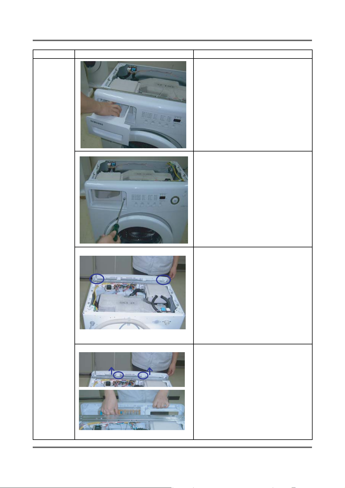
Part Name Descriptive Picture How To Do
FRAME
FRONT
ķ Remove the Top Cover and the Assy
Drawer.
ĸ Remove the one screw on the front of the
control panel.
Ĺ Remove the two screws on the plate(u).
ĺRemove the control panel by disconnecting
the connector that connects PCB to the
wire-harness.
25
Page 26
Part Name Descriptive Picture How To Do
FRAM
FRONT
Ļ Remove the assy-panel control.
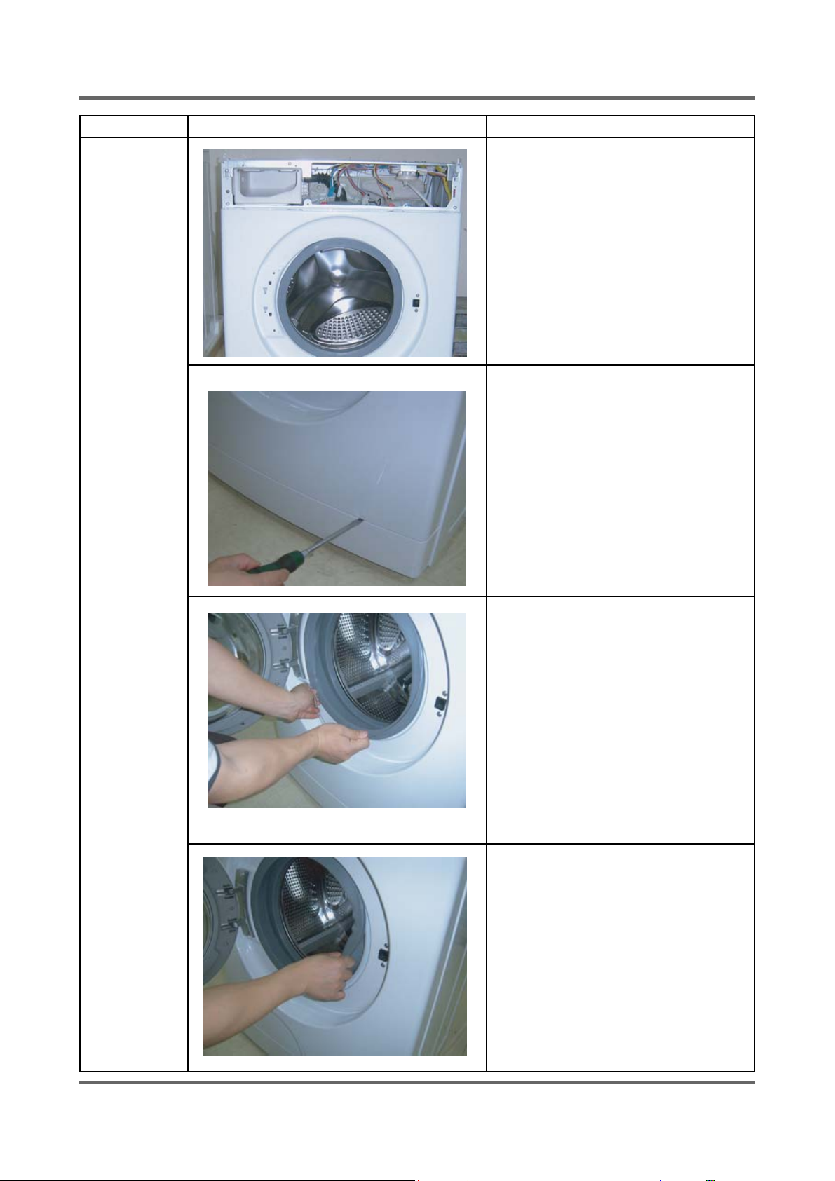
ļInsert a fl at head screwdriver into the gap
and pry down the Cover Front (Left) to
separate it.
Ľ Remove the Wire Diaphragm from the
Frame Front.
ľ8nseat the Diaphragm.
26
Page 27
Part Name Descriptive Picture How To Do
FRAM
FRONT
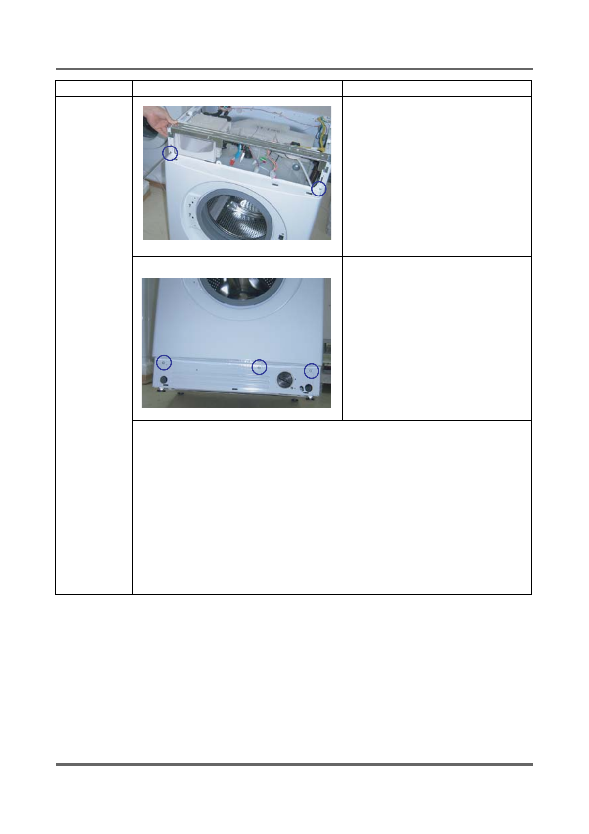
Ŀ Remove the 2 screws on the Frame Front.
ŀRemove the 3 screws on the bottom of
Frame Front.
27
Page 28
Part Name Descriptive Picture How To Do
BELT
Before removing the belt, should be opened
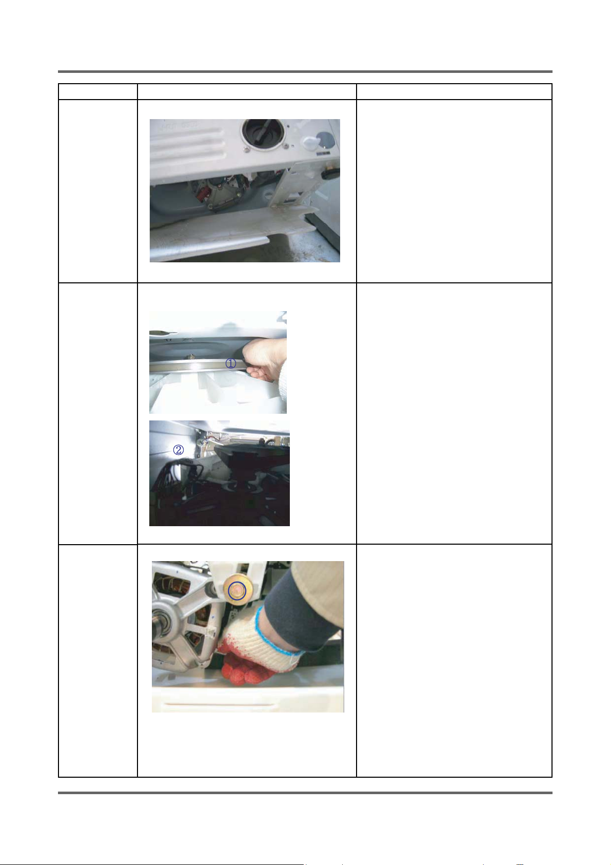
the cover bottom.
ķ Remove the belt before the re-assembly.
ĸEnsure the belt is placed on the center
of the motor pulley.
<Belt assembly>
Hang the belt on the motor pulley(ķ).
Before placing it around the pulley(ĸ).
MOTOR
ķ Remove the wire housing from the motor.
ĸ Remove the bolts holding the motor by
using the power screwdriver.
Ĺ Remove the motor.
28
Page 29
Part Name Descriptive Picture How To Do
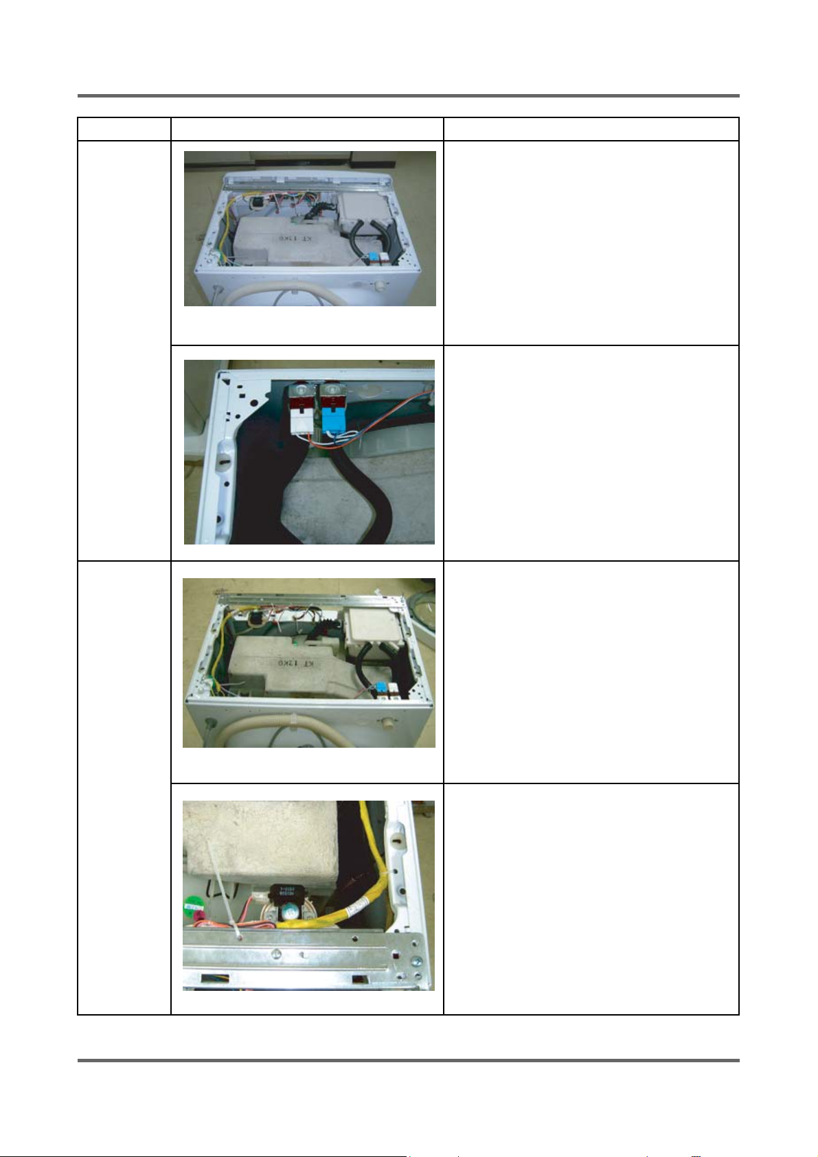
Water Supply
Valve
ķ Remove the fi xing screws for the water
supply valve.
ĸ Disconnect the valve wires.
Ĺ Separate the water hoses.
Water Level
Sensor
ķRemove the top cover.
ĸRemove the fi xing screws for the water
level sensor.
Ĺ Disconnect the water level sensor harness.
ĺ Disconnect the hose pressure.
Ļ Replace the water level sensor.
29
Page 30
Part Name Descriptive Picture How To Do
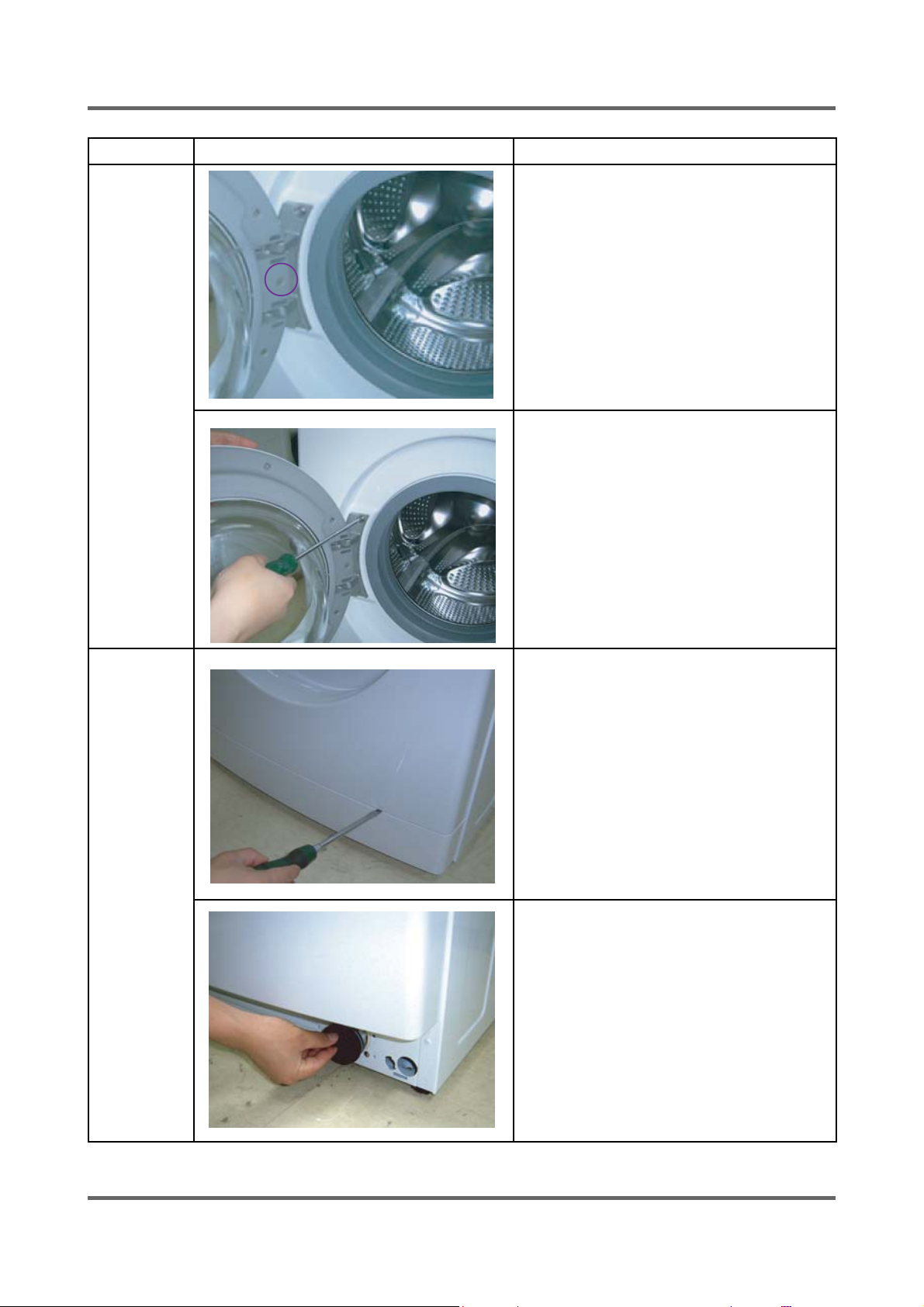
Door-Hinge
ķ Remove the fi xing screws holding the
Door-Glass.
ĸ Separate the glass.
Ĺ After removing the two screws holding the
Holder Glass, replace the Door Hinge.
ĺ After putting them back together, check
if the screws holding the Door Hinge is
fastened properly.
Drain Pump
ķ Insert the fl at head screwdriver into the
slot on the top of the Cover Filter and
lever it down to separate it.
ĸ Unscrew the drain fi lter by turning it
counter clockwise.
The water remaining inside could fl ow out.
So, put an empty bowl on the fl oor to hold
the water.
30
Page 31
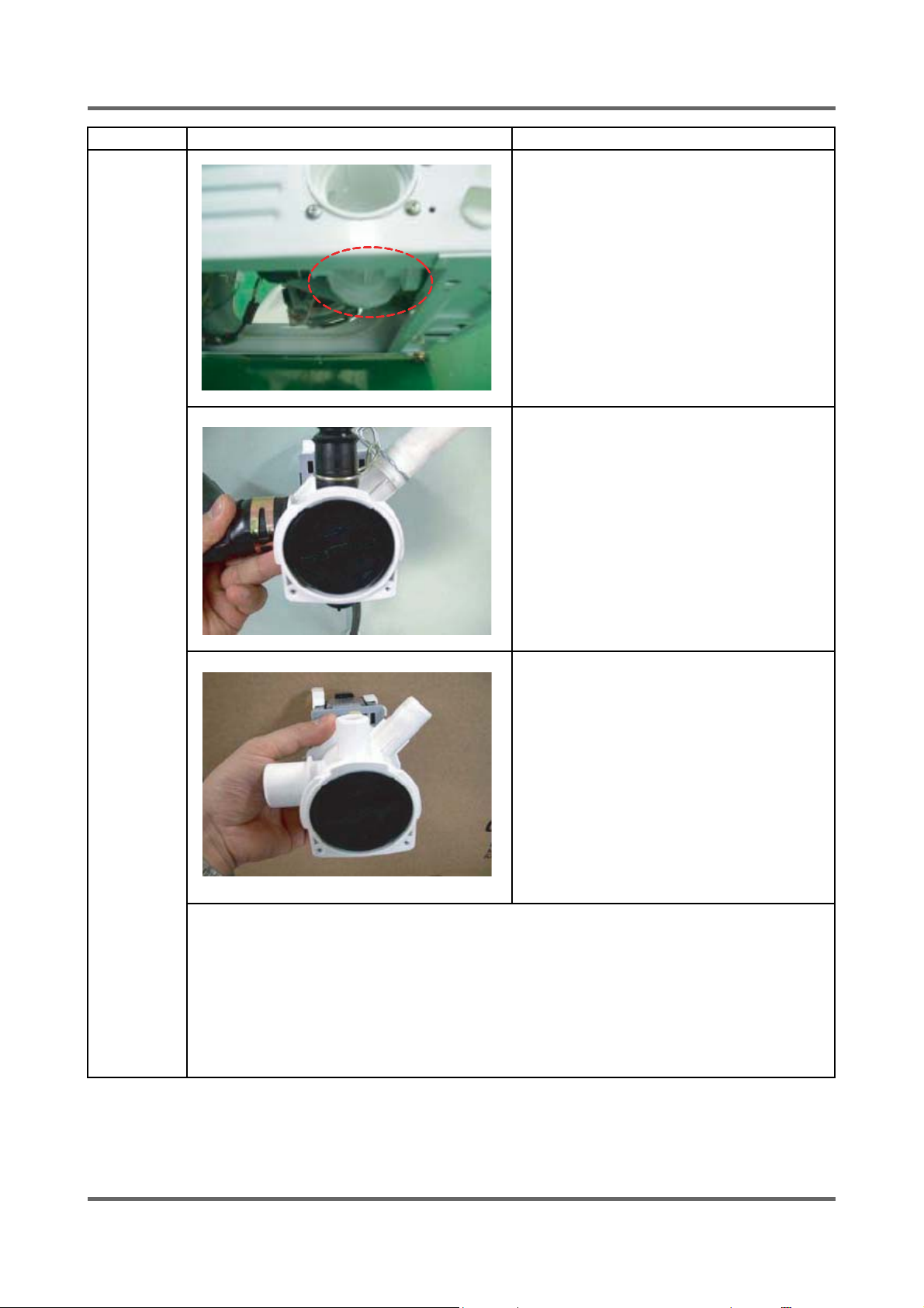
Part Name Descriptive Picture How To Do
Ĺ Tilt the unit backward and take out the
drain pump.
ĺ Disconnect the incoming water hose and
the wire harness.
(Caution: Check if the unit is plugged out.
There is possibility of electric shock.)
Ļ Separate the Hose Filter Tub and the Drain
Hose.
Ć CHECK POINT
1. Remove the Drain Filter and check if there are foreign substances (coin, buttons, etc)
blocking inside - If so, clear the inside.
2. Check if the wire harness is connected properly - If not, connect it properly.
3. If water leaks, check if the Clamp Hose and the Cap Drain are assembled tightly
- If not, assemble them tightly.
Remove the water remaining inside by turning the Filter counter clockwise.
31
Page 32

Part Name Descriptive Picture
How To Do
Door S/W
ķ Open the Door.
ĸ Remove the Spring Diaphragm and separate
the Diaphragm from the Frame Front.
- Insert the fl at head screwdriver and pry up
the spring to remove the Spring Diaphragm.
- The Diaphragm could get damaged when
taking it out. So, unseat it in one
direction slowly.
Ĺ Remove the screws holding the Door S/W.
ĺ Take out the Door S/W.
Ļ Disconnect the wire connector. (Press the
hook to unlock the tab and plug it out.)
32
Page 33
Part Name Descriptive Picture
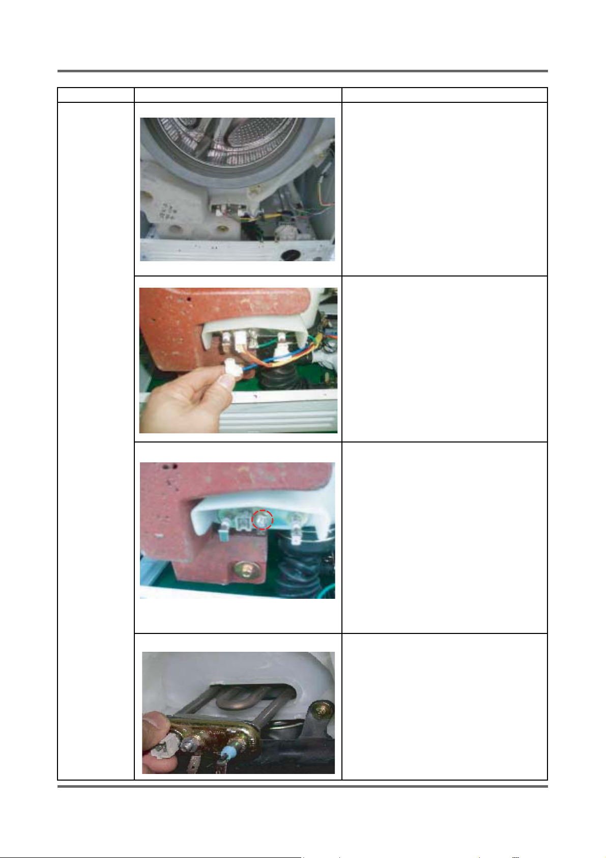
How To Do
Heater
ķ Remove the frame front.
ĸ Disconnect the connector housing.
Ĺ Remove the nut holding the heater and separate
the heater.
ĺ Take out the heater from the tub.
(
ĆCaution: Be sure to insert the heater into the
Bracket in the tub. If not, it may cause a fi re.
And, make sure to have the packing seating on
it’s place. fasten the nut with 5 kg/cm
is fastened loosely, it may cause water leakage.)
2
.If the nut
33
Page 34
6. TROUBLE DIAGNOSIS
6-1. TROUBLE DIAGNOSIS
- As the micom wash machine is confi gured of the complicate structure, there might be the
service call.
Below information is prepared for exact trouble diagnosis and suitable repair guide.
Caution for the Repair and Replacement
Please follow below instruction for the trouble diagnosis and parts replacement.
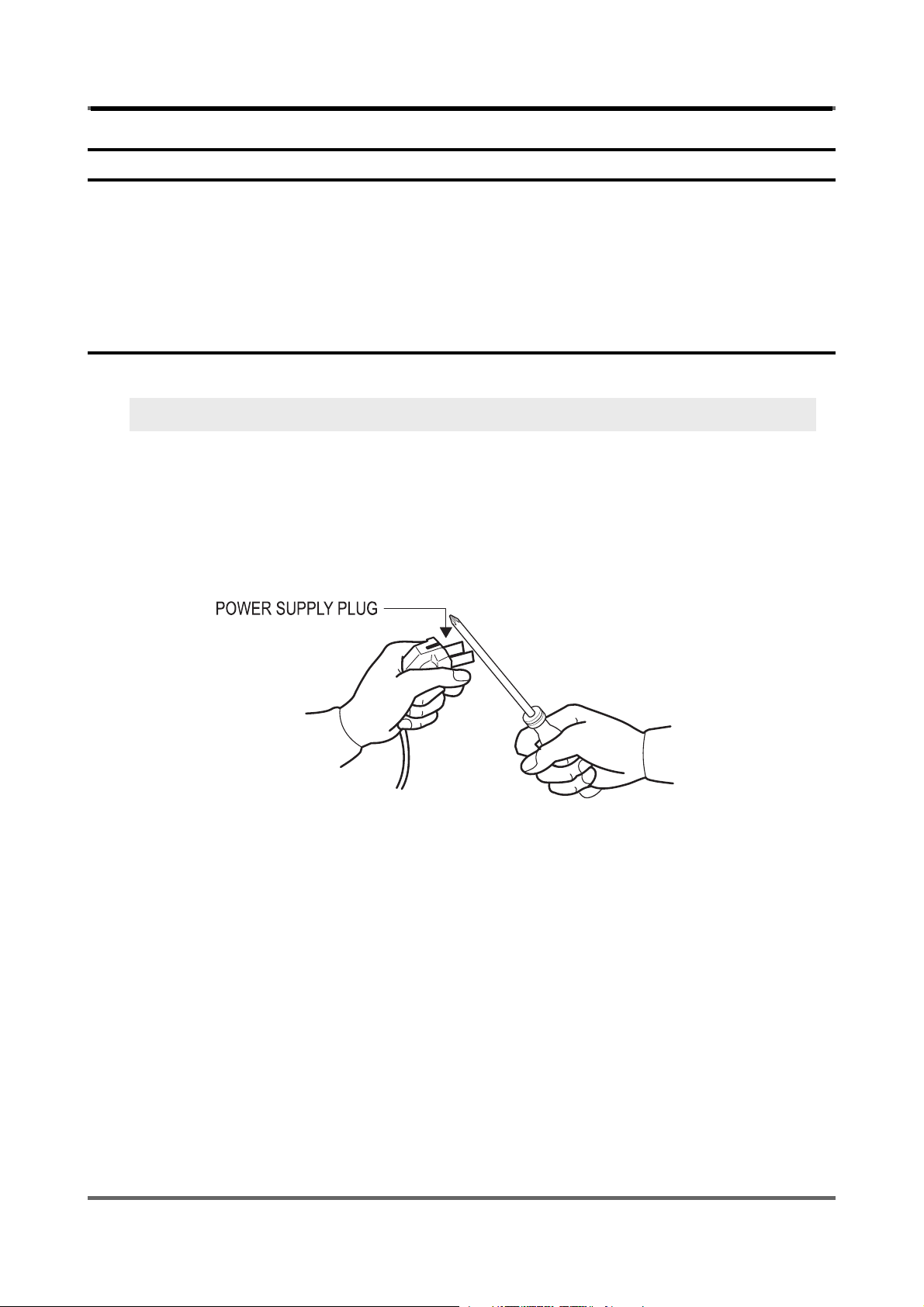
1) As some electronic components are damaged by the charged static electricity from the resin
part of wash machine or the human body, prepare the human body earth or remove the poten
difference of the human body and wash machine by contacting the power supply plug when
work contacting to PCB is executed.
2) Since AC 220~240V is applied to the triac T1 and T2 on P.C.B, the electric shock may occur by touching
and be careful that the strong and weak electricity are mixed.
3) As the P.C.B assembly is designed for no trouble, do not replace the P.C.B assembly by the
wrong diagnosis and follow the procedure of the trouble diagnosis when the micom is not op
erated normally.
34
Page 35
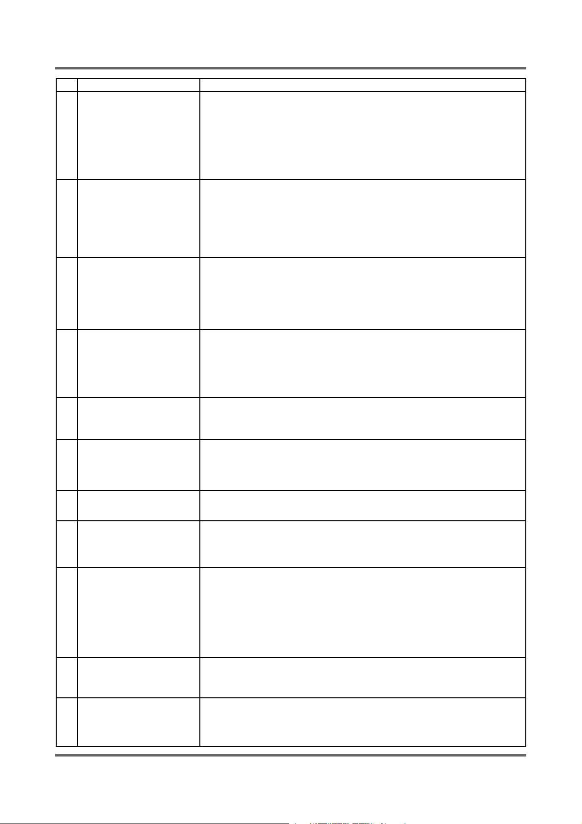
No Item Cause and treatment
- Is the PCB connector connected well?
- Is the voltage normal?
- Is the power supply plug connected well?
1 The power is not supplied
2 The water is not supplied.
- Is the noise fi lter connected well?
- Is the secondary output of the power supply transformation normal?
- Is the fuse disconnected? (option)
• If above points are not found, the PCB assembly is out of order.
Replace it.
- Is the knob open?
- Did you push START/PAUSE button after selecting the course?
- Is the water supply valve connected well?
- Is the winding of the water supply valve continuous?
- Is the connection and operation of the pressure switch normal?
• If above points are not found, the PCB assembly is out of order.
Replace it.
The wash does not start
though the water supply is
3
stopped.
The drum does not rotate
4
during washing.
The drum rotates by one
direction during washing.
5
(The drum rotates to one
direction for SPIN.)
6 Drainage problem.
Dehydration problem.
7
8 Abnormal noise during SPIN.
- Is the connection and operation of the pressure switch normal?
- Is the pressure switch hose damaged so that the air is leaked?
- Is the pressure switch hose bent?
- Check the operation of the water level switch.
• If above points are not found, the PCB assembly is out of order.
Replace it.
- Is the belt connected well?
- Is the winding of the motor continuous?
(Rotor winding, stator winding, generator)
- Is the motor protector normal?
• If above points are not found, the PCB assembly is out of order.
Replace it.
- The PCB assembly is out of order. Replace it.
(Inversion relay open trouble)
- Is the drainage hose bent?
- Is the winding of the drainage pump continuous?
- Is the drain fi lter clogged by the waste?
• If above points are not found, the PCB assembly is out of order.
Replace it.
- The unbalance is detected.
- Put in the laundry uniformly and start again.
- Is the pulley nut loosen?
- Is the transport safety device removed?
- Is the product installed on the level and stable place?
(Little noise may be generated during the high-speed SPIN.)
Leak breaker or current/leak
9
breaker is down during washing.
10 The heater is not executed
11
Do not open the door
<When the leak breaker and current breaker is installed separately>
- When the leak breaker is down, check and make the earth of the outlet.
- When the current is down, the current is leaked.
<Is the breaker down when the leak/current breaker is combined?>
- Check the rated capacity of the current and leak breaker.
The current breaker may be down due to the lack of the current when the wash
machine and other apparatus are used.
In this case, execute the cold water wash to check whether the current capacity
is lack.
- Is the wash heater terminal unplugged.
- Is the wash heater normal.
- If above points are not found,the PCB assembly is out of order. Replace it.
- Disconnect the power supply.
- Remove the water from the washing machine.
- Use a screwdriver to the pop on the plastic base cover,set it aside.
- Locate the orange plastic tub and pull forward to open the door.
35
Page 36
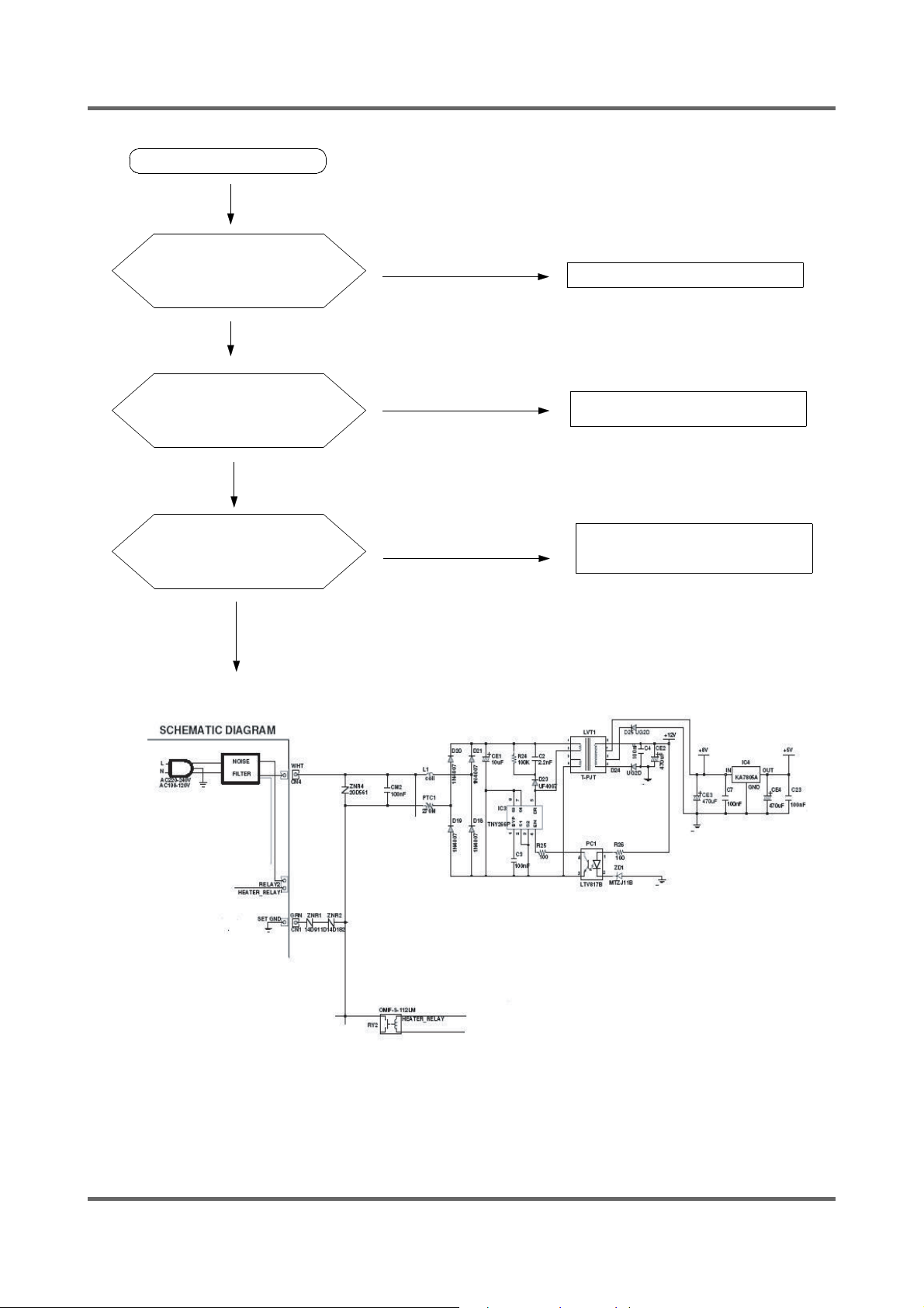
6-2. PROBLEM CHECKING AND METHOD OF PCB
6-2-1. The Part Of Power Source
NO Power On
YES
The Voltage
BetweeneandfIs
DC 300V?
YES
NO
Check The DIODE(D18~D21)
The Voltage
Betweenaandbis
DC 12V?
YES
The Voltage
Between d and b is
YES
ok
DC 5V
NO
Check LVT1
NO
?
e
Exchange IC4(7805)And Check
The condenser(CE4)
And IC3
a
c
b
d
36
¤—
f
Page 37
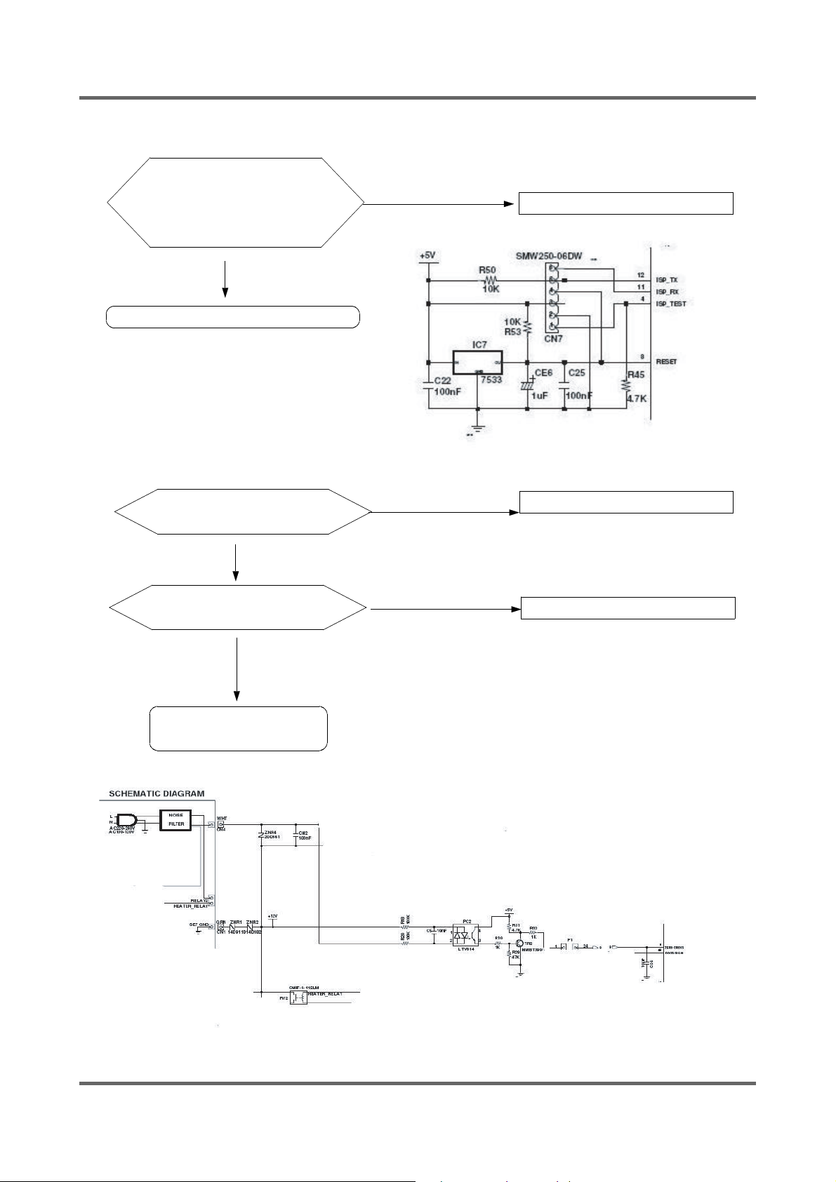
6-2-2. Reset Part
The Value Of
Measurement Result
Between Micom 8 And
Gnd Is 5V?
Check IC7
6-2-3. Interrupt Part
YES
NO
Check The Power Source
Check The Curve
Output Of
Check The Micom
Number 9?
Check The Part Of
Oscillator
¤˝
?
Y
Y
N
N
Check PC2
Check TR2,R32
37
a
Page 38
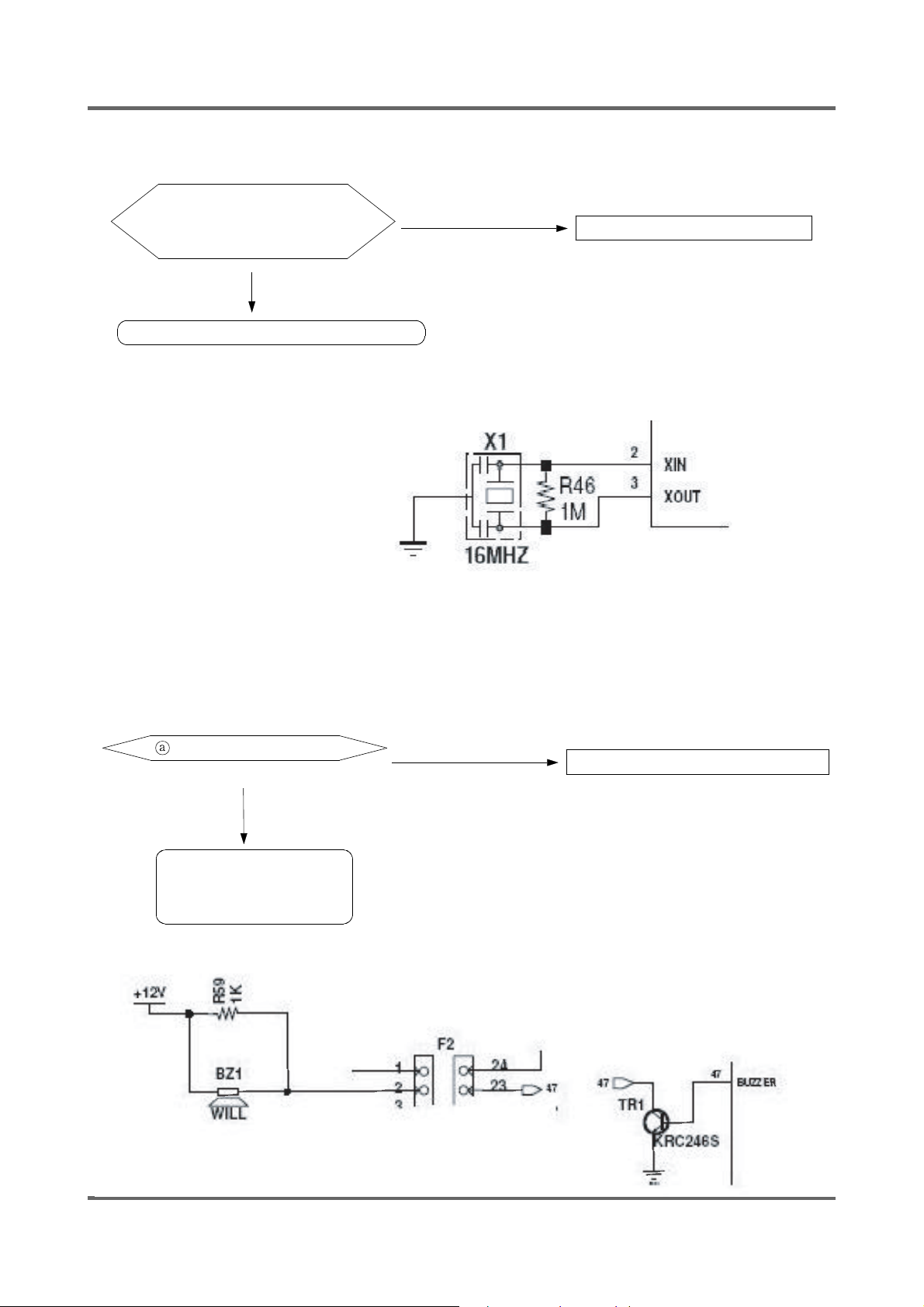
6-2-4. Checking The Part Of An Oscillator
When The Micom 2,3
Check, The Value Is
16Mhz?
YES
Exchange Micom
NO
Check Resonator R46
6-2-5. Check The Part Of Buzzer
Part is DC12V ?
YES
Exchange BZ1,
Check TR1,R59, Micom
47
NO
Check The Part Of Power Source
38
Page 39
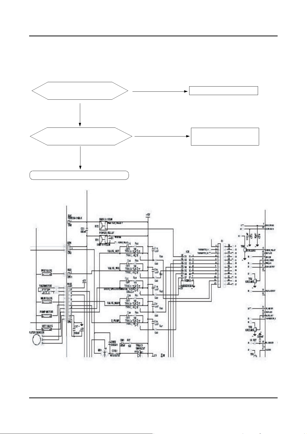
6-2-6. Driving Part Checking
ƹ Confi rm The Output Of DC5V, When The Every Part Of Micom Number Check, According To Some
Problem and Condition.
ex) When The Drain Is Not Operating But Pump Motor Is Operating, Check The Voltage Of Micom is 5V.
Micom Number 31 Is
5 Voltage?
YES
The Part Of a is
0 Voltage?
YES
Check R47, TRIAC4
NO
NO
Micom Bad
Check The IC6
KID65003AP
¤˝
a
Ć Check The Micom 18th In The Above Method When The Cold Water Is Bad
39
Page 40
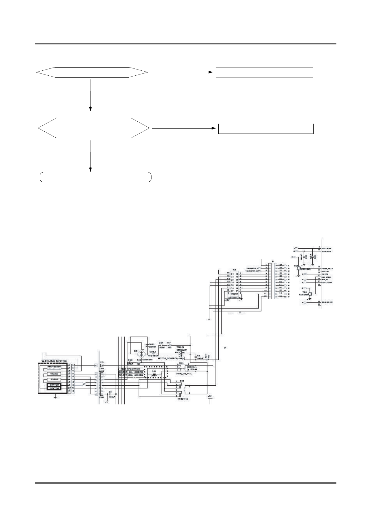
6-2-7. Confi rm The Driving Part Of Motor
Motor Is Not Spinning
NO
Motor Is Not Turning
Right And Left
NO
Check The Tacho Part
YES
YES
Check BD1, TRIAC1
Check RELAY3
40
Page 41
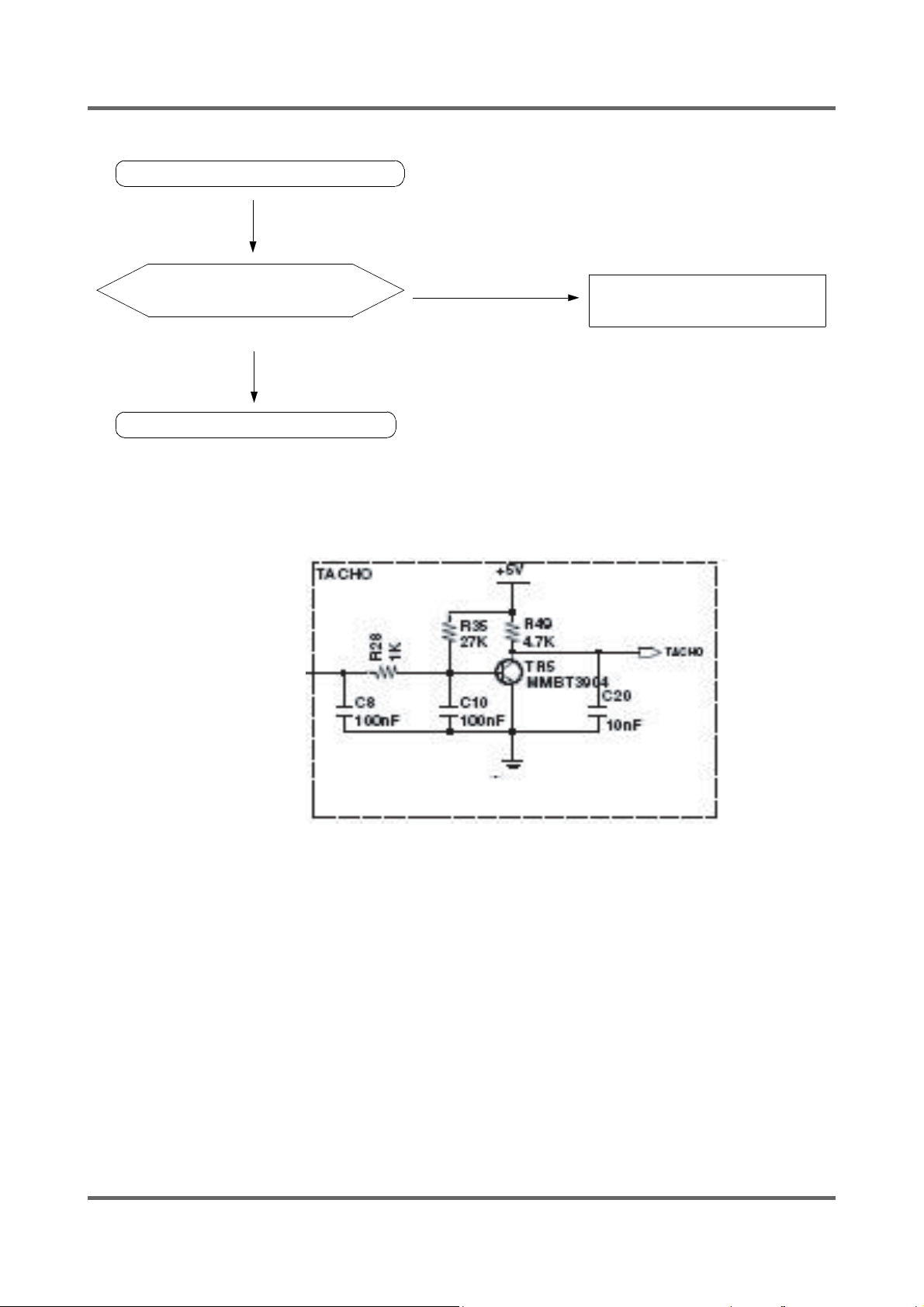
6-2-8. Checking The Tacho Part
Have The Motor Turn In Hand
Is The Rectangular
Curve In The Micom 13?
YES
Exchange The Motor
NO
Check The Surroundings
Circuit And TR5
41
Page 42
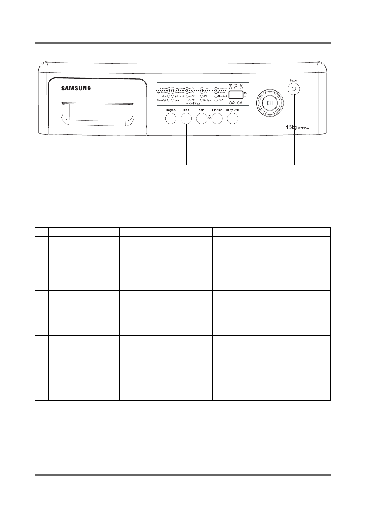
6-3. DETAILED DIAGNOSIS
ķǂĸǂĹĺ
1. Driving Compartment Test Mode
A. Hold down the ķ and the ĸ buttons simultaneously and then press the Power button ĺ.
(All of the LEDs li ght up and the display shows t1 in 2 seconds.)
B. The driving part can be tested when you press the push button dial Ĺ right after entering
into the TEST MODE.
No Check Test Method Description
Motor Wiring (Red/Whiteķ/Blue/Pink/
Violet/Whiteĸ)
Resistance between Blue-Red,
Red-Whiteķand Whiteķ-Blue should be
2.0Ω±10%.
Check resistance of the Water Valve
terminals.
Check resistance of the Drain Pump
terminals.
Check resistance of the Door S/W
terminals.
Check frequency (Hz) between the Water
Pressure Sensor terminals.
1.Replace the SUB PCB.
2.If not, replace the Noise Filter.
1 Motor
2 Water Valve
3 Drain Pump
4 Door S/W
5 Water Pressure Sensor
6 MAIN PCB
Check if the motor operates or
check the Motor terminals.
Check if it supplies water or check
the Water Valve terminals.
Check if it drains normally or check
the pump terminals.
Check if it works at the Cotton
course or check the Door S/W
terminals.
Refer to Page 15.
(Water Level Table at each
Course)
1. Press the buttons on the display.
Check if all of the LEDs work.
2.Check if voltage between the
white and the black terminals
is 220~240V.
2.THERMISTOR TEST MODE
A. Hold down “ķ” and “ĸ” keys simultaneously and then press POWER S/W “ĺ” on.
(Whole lamps turn on and display show “t1” after 2 Seconds.)
B. Press the “Delay start” key and display shows “t2”.
C. Press the “Start/Pause” key and display shows the inside temperature of tub.
42
Page 43
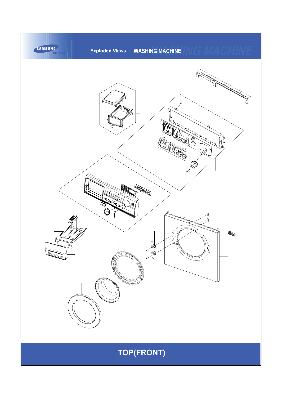
7. EXPLODED VIEWS AND PARTS LIST
7-1. EXPLODED VIEWS OF TOP(FRONT)
C0002
C0043
F0125
R0019
C0115
R0036
A0328
D0010
C0058
C0044
D0072
D0045
F0064
D0061
43
Page 44
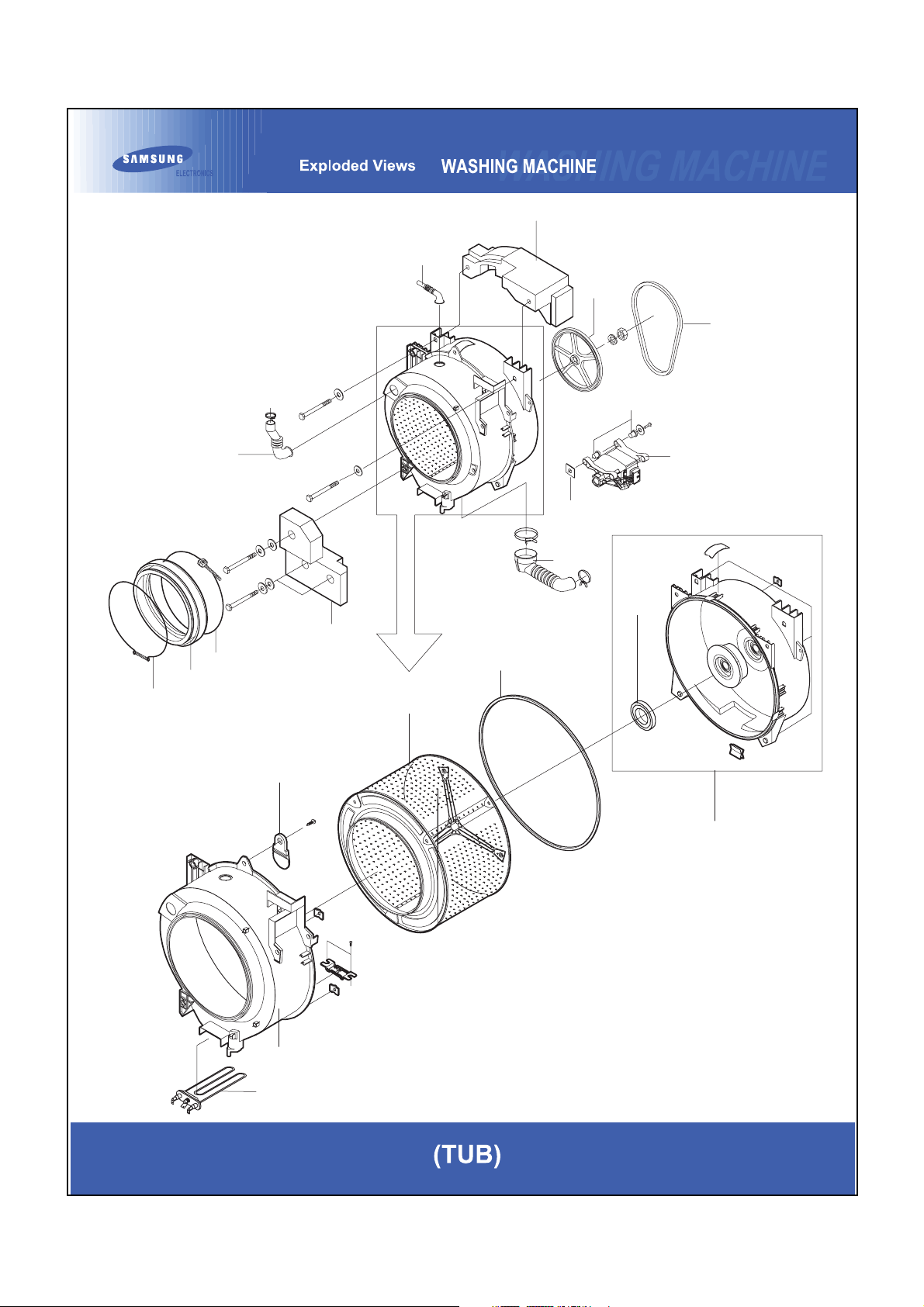
7-2. EXPLODED VIEWS OF TUB
U0355
I0043
U0010
U0095
U0307
R0030
R0158
U0029
U0038
U0015
U0023
U0033
U0016
U0355
U0328
R0001
U0035
U0013
U0030
U0018
44
Page 45
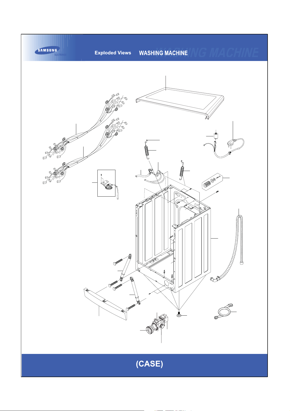
7-3. EXPLODED VIEWS OF CASE
P0001
W0004
W0001
R0027
R0158
W0002
Y0040
A0115
R0159
R0021
R0159
A0025
I0022
F0027
A0006
U0133
U0133
U0359
45
J0019
J0013
J0025
B0070
I0040
Page 46
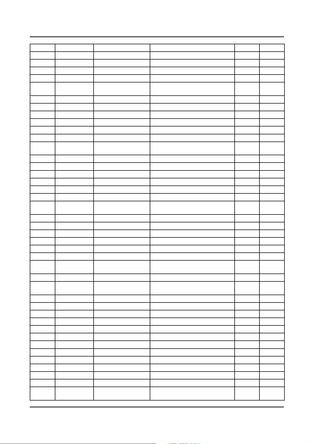
7-4. PARTS LIST
SVCcod Low Material Description SPECIFICATION Qty SA/SNA
A0006 DC63-00625A COVER-FRONT(L) SEW-DR803BT,PP,-,-,-,-,-, 1 SA
A0025 DC97-02106C ASSY-FIXER TUB SEW-3HR105,L114.5 5 SA
A0034 DC60-40146A BOLT-SPANER -,HR,-,T2.3,OD36,-,BLK,-,- 1 SA
A0043 DC61-10688A CAP-FIXER SWF-P12,PP(TB53),-,-,-,WHT,-, 5 SA
A0114 DC64-00587A SHUTTER Q1636GW/XEU,DNAPLA,-,-,-
,WHT,PP(
A0115 DC61-60180A SLEEVE-PLUG NYLON#6,SEW-720DR,-,-,NTR 2 SA
A0132 DC61-10673A CAP-DRAIN SWF-P12,PP(TB53),-,-,-,WHT,-, 1 SA
A0282 DC63-00414B COVER-BACK SEW-3HR103BT,GI,T0.4,-,-,-,-, 1 SA
A0332 DC62-10290B HOSE-WATER(H) WIP4013SRW,PVC+NYLON,ID10. 1 SA
A0362 DC61-40081A HOLDER-WIRE DAWH-2NC,NYLON66,-,-,-,-,NTR 5 SA
B0070 DC97-00920C ASSY-LEG SEW-HW108,- 4 SA
C0002 DC97-12535Q ASSY-PANEL CON-
TROL
C0043 DC64-01228B BUTTON-PUSH(F) CATS2-PJT,ABS,-,-,NEAT-WH 1 SA
C0044 DC64-01229A BUTTON-PUSH(P) CATS2-PJT,ABS,-,-,-,- 1 SA
C0058 DC64-00120E DOOR-LOCK S/W 760DR,NYLON,-,WHT,-,-,VDE/ 1 SA
C0075 DC64-01226A KNOB-ENCODER CATS2-PJT,ABS,-,-,-,-,-,-,- 1 SA
C0075 DC64-01227A BUTTON-ENCODER CATS2-PJT,ABS,-,-,-,- 1 SA
C0103 DC66-00141A LEVER-DOOR P1092,ZnDC,-,-,-,-,-,DOOR LOC 1 SA
C0115 MFS-C2J14NA-01ASSY-PCB PARTS(M) MFS-C2J14NA- 1 SA
J1484T/HAC,HOT+COLD 1 SA
1SA
C0116 DC66-30160A LEVER PE,L335,SWF-P12(ORG) 1 SA
D0010 DC97-04751D ASSY-COVER DOOR P1405J/SEW-660DW,CR_COAT 1 SA
D0045 DC97-03423A ASSY-HOLDER GLASS P1405J,ABS,WHT,CUSION- 1 SA
D0061 DC64-00920C DOOR-GLASS S,P,F MODEL(LOW),GLASS,T5.0,H 1 SA
D0109 DC61-60519A GUIDE-BAR SWF-P12,SHV-745CC1(SSEC),-,-,- 2 SA
F0027 DC99-00662A ASSY-PAINT FRAME WF-J1456C,T1.0/NEAT-WHT 1 SA
F0060 DC96-00775A ASSY-BRACKET
FRAME
F0064 DC97-00416A ASSY-FRAME FRONT SWF-P12,FRAME-FRONT 1 SA
F0065 DC97-05134C ASSY-FRAME
PLATE(U)
I0003 DC62-10289C HOSE-WATER(C) RUSSIA,PVC+NYLON,ID10.3,-, 1 SA
I0022 DC97-02250F ASSY-HOSE DRAIN(O) B1415J(NO-SPONGE),EPD 1 SA
I0030 DC62-10278A HOSE-HANGER -,PP(JS20),-,-,-,-,NTR,- 1 SA
I0041 DC62-10311A HOSE-PRESSURE -,EPDM,ID13.5,-,-,-,BLK,SW 1 SA
I0043 DC62-10303A HOSE-AIR -,EPDM,ID24,-,-,L130,BLK,SWF-P1 1 SA
I0046 DC62-10302A HOSE-DRAIN SWF-P12,EPDM,ID5.5,-,-,L220,B 1 SA
J0019 DC61-10652B CASE-PUMP PP(5113MF6),SW-5C1P,-,-,-,WHT, 1 SA
J0020 DC63-00443B COVER-PUMP SEW-HR125,PP,T1.3,-,-,-,-,WHT 1 SA
J0025 DC31-30008D PUMP-DRAIN SW-70XP,220/240V,50Hz,SYNCHRO 1 SA
P0001 DC97-09921F ASSY-COVER TOP J1484/HAC,MDF/NEAT-WHT WI 1 SA
R0001 DC97-05848B ASSY-DRUM J1455AVIW/XSA,JUMP2-PJT/SSEC 1 SA
R0007 DC97-05103A ASSY-FLANGE SHAFT Q1435V,ALDC+SM45C/FOR6 1 SA
R0019 DC97-11440G ASSY-HOUSING
DRAWER
TS2-PJT,SPONGE ADD 1 SA
WF-B125AV/YLP,T-PJT/ 1 SA
J2 HOT+COLD,HOT+COLD 1 SA
46
Page 47
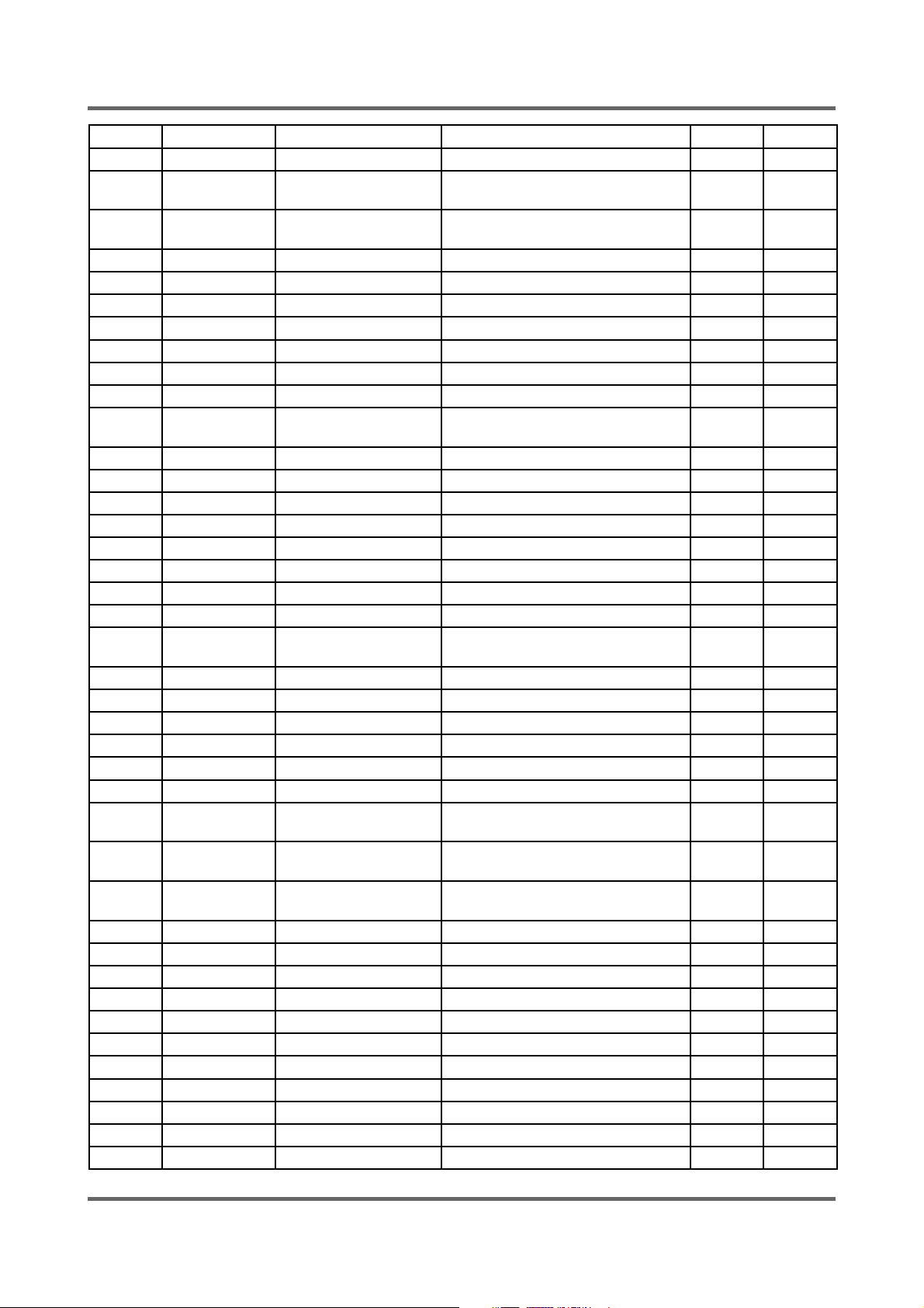
7-4. PARTS LIST
SVCcod Low Material Description SPECIFICATION Qty SA/SNA
R0025 DC97-11386A ASSY-PANEL DRAWER CAT’S 2 -PJT,- 1 SA
R0027 DC97-00731A ASSY-SENSOR PRES-
SURE
R0030 DC91-12078C ASSY-WIRE DIA-
PHRAGM
R0036 DC61-01616A BODY-DRAWER STANDARD(B/P/J),PP,-,-,-,-,- 1 SA
R0106 DD60-50018A NUT-FLANGE -,M5XP0.8,FZY,MSWR10,- 2 SA
R0124 DC61-01416A STOPPER-DRAWER T-PJT,POM(F20-02),T2.5,-, 1 SA
R0158 DC62-10305A HOSE-DRAWER TUB -,EPDM,ID35,-,-,L158,BLK 1 SA
R0158 DC67-00051D HOSE-DRAWER S1093~S6093,EPDM,-,-,-,-,BLK 0.68 SA
R0159 DC61-00952A SPRING-HANGER SEW-3HR105,-,CD3.5,-,OD25. 2 SA
U0003 DC60-60044A WASHER-PLAIN -,ID10.5,OD30,T3,-,STS304 2 SA
U0010 DC66-00327A PULLEY Q1636GW/XEU,ALDC8-1,-,-,-
U0012 DC61-01447A BRACKET-HEATER V7,STS430,T0.6mm,W30mm,L1 1 SA
U0015 DC31-00002A MOTOR-DRUM MCC52/64-148/SEC2,220~240V,50 1 SA
U0016 DC62-00160A SEAL-OIL TS0-PJT,NBR(SD35),BLK,-,-,-,JIN 1 SA
U0018 DC47-00007A HEATER -,DRUM-MDL,SUS316L,-,-,230V,20,-, 1 SA
U0023 DC61-00201A BRACKET-NUT SBHG-R,P1291,T3,-,-,-,NO-PAI 1 SA
U0023 DC61-40348B BRACKET-NUT SBHG-R,P1291,T3,-,-,-,NO-PAI 5 SA
U0023 DC61-40348B BRACKET-NUT SBHG-R,P1291,T3,-,-,-,NO-PAI 2 SA
U0029 DC61-20219E DOOR-DIAPHRAGM SEW-HW107,EPDM,-,-,-,-,GR 1 SA
U0030 DC61-30346C TUB-FRONT P1405J,FRPP(FRPP15%)SAMBAC
U0033 DC62-10304A HOSE-FILTER TUB -,EPDM,ID65,-,-,L151,BLK 1 SA
U0035 DC62-20311A VANE-CHECK SWF-P12,EPDM,-,-,BLK,-, 1 SA
U0078 DC97-10977K ASSY-SEMI TUB BACK J1455,FRPP(GF15%) 1 SA
U0086 DC67-00079A WEIGHT-BALANCER(F) SEW-HW107,FE,-,-,-,RE 1 SA
U0095 6602-001199 BELT-TIMING GEAR 1275JMA,POLYURETHAN,T3. 1 SA
U0133 DC66-00421A DAMPER-SHOCK F-PJT,FRICTION-DAMPER,-,-,- 2 SA
U0320 6011-001497 BOLT-HEX M7,L112.5(44),ZPC(YEL),SWRCH1
U0320 DC60-40141A BOLT-HEX SM10C/DAMPER,HEX,M8,L66,-
U0320 DC60-40144A BOLT-HEX M10,L41,ZPC2(YEL),SM10C/DAMP-
U0328 DC62-40183A PACKING-TUB SWF-P12,EPDM,-,-,-,-,-,BLK,- 1 SA
U0353 DC61-60359E CLAMPER HOSE F1235AS/F1035AS,-,-,ID7.8,Y 1 SA
U0353 DC61-60497A CLAMPER HOSE SWF-P12,HSWR,-,ID70/OD75.8, 1 SA
U0353 DC61-60359G CLAMPER HOSE F1235AS/F1035AS,-,-,ID37.2, 1 SA
U0353 DC61-00133A CLAMPER HOSE P1291,PP(BJ-730),ID24.5,OD2 1 SA
U0355 DC67-00105A WEIGHT-BALANCER SEW-3HR105,GC-150,-,-,-, 1 SA
U0355 DC67-00106A WEIGHT-BALANCER SEW-3HR105,GC-150,-,-,-, 1 SA
U0359 DC62-00066A FILTER-CASE -,PP,-,-,-,-,BLK/SW90V2 1 SA
U0360 DC61-60499B CLIP-TUB HSWR,P1291,-,NO/PAINT, 8 SA
U0360 DC61-60520A CLIP-TUB SK5,SWF-P12,-,PLATE-TYPE, 2 SA
W0001 DC96-00989B ASSY-WIRE HARNESS J1484/HAC,AC220V/50Hz/ 1 SA
P1091,S-PRE+BRAKET+ 1 SA
TS-2,Q1636,FE,SW-C,Z 1 SA
1SA
,OD296.8
1SA
K,-,
1SA
8A
2SA
,ZPC2(
2SA
ER
47
Page 48
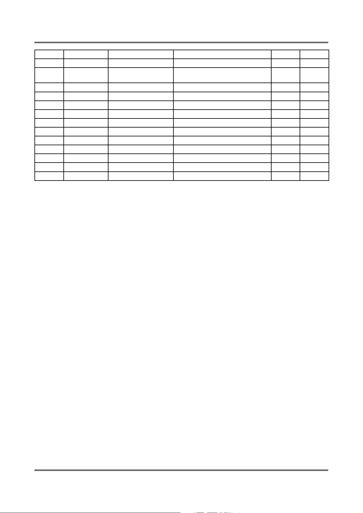
7-4. PARTS LIST
SVCcod Low Material Description SPECIFICATION Qty SA/SNA
W0002 DC96-00146A ASSY POWER CORD UCP2,-,250V/16A,-,-,-,-, 1 SA
W0004 DC96-00954C ASSY-M.WIRE HAR-
NESS
W0010 DC63-00651A COVER-HEATER Q1657TGW/XEU,GI,T0.4,-,-,-, 1 SA
W0031 DC65-60118K BAND-RING HSWR,YEL,PI2.0,OD22,ID18 1 SA
W0031 DC65-60118J BAND-RING -,HSWR,-,-,-,YEL,PI2.0/ID23 1 SA
W0032 DC62-00024F VALVE-WATER B1215J,NYLON66/250TRMN,-,-,N 1 SA
W0032 DC62-30314A VALVE-WATER SWF-P12,NYLON#6,-,-,-,EATON( 1 SA
Y0035 DE65-20026A CABLE CLAMP -,NYLON66,-,NYLON66,NTR,NTR, 2 SA
Y0040 DC29-00005B FILTER-EMI FA-2151T-2,1.2MM NUT,250V,15A 1 SA
Z0006 DC97-02412A ASSY-BOLT SWF-P12,MOTOR, M8*L62 3 SA
Z0006 DC97-02412B ASSY-BOLT SWF-P12,WEIHGT(L)/M8*L147 1 SA
Z0006 DC97-02412D ASSY-BOLT Q1636,WEIHGT(U)/M8*L103 1 SA
Z0006 DC97-02412H ASSY-BOLT Q1657,- 1 SA
CAT’S 2 B1182T/HAC M 1 SA
48
Page 49
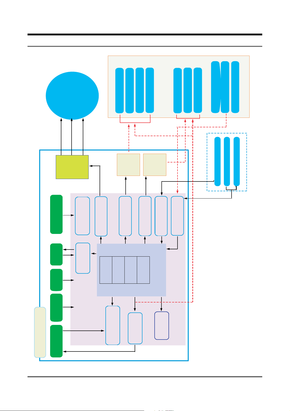
8. BLOCK DIAGRAM
AC ZERO CROSSING
MOTOR
UNIVERSAL
ML
MOTOR
CW/CCW
CONTROL
RELAY
DETECT CIRCUIT
POWER
MR
CONTROL DRIVE
MAIN MOTOR
CONTROL DRIVE
PRE-VALVE
DRIVE
ACTUATOR CONTROL
HOT-VALVE
COLD-VALVE
CONTROL
TRIAC
DRIVE
DOOR CONTROL
DRAIN PUMP
DRIVE
CONTROL
DRIVE
RELAY
FREQUENCY
DOOR-COM
CHECK DRIVE
AD COVERTER
CONTROL
DOOR-LOCK
DOOR-UNLOCK
DOOR-CLOSE SIG
WATER LEVEL SENSOR
DOOR-LOCK SIG
WATER THERMISTOR
DOOR-UNLOCK SIG
HEAT SINK THERMISTOR
EEPROM
RESET
OSCILLA TION
DISPLAY
MAIN PBA
CIRCUIT
CIRCUIT
DRIVE
EEPROM
PRE WASH
RINSE
SPIN
CPU
WASH
MAIN MICOM
CIRCUIT
DISPLAY
CONTROL DRIVE
CIRCUIT
ERROR
CONTROL
49
CONTROL
AG DIRVE
Page 50
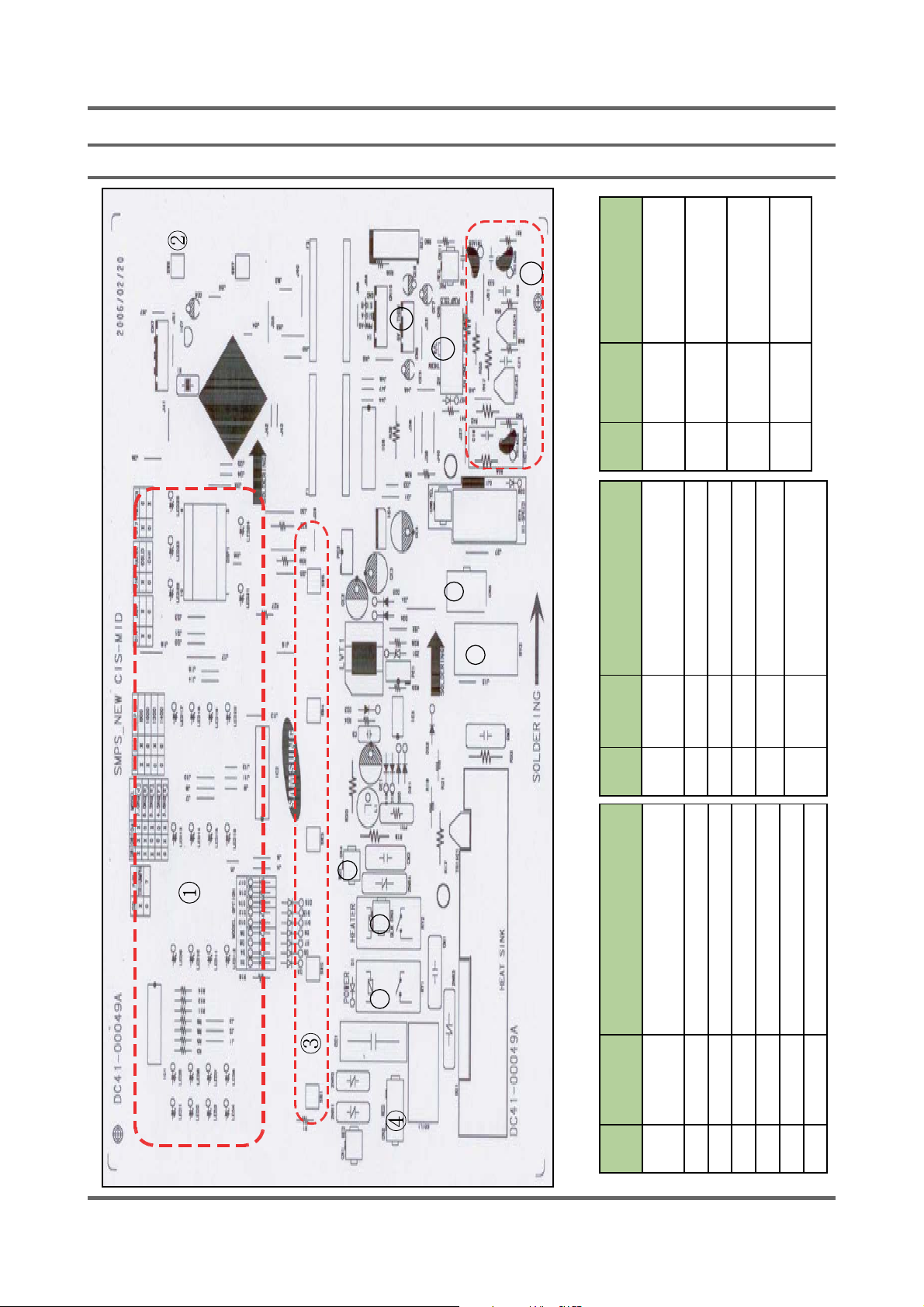
9. WIRING DIAGRAM
9-1. PCB ASSY’ LAYOUT
10
11
12
Description
system wire
valve wire
nano wire
sink thermistor
Number
Item Part
14 CN8 Connect the driving
15 CN11 Connect to the pre
16 CN10 Connect to the silver
17 CN9 Connect to the heat
9
8
Description
power
Number
Operating parts as cold/hot/
drain/door
ing part
7
56
50
Item Part
8 BD1 Convert AC into DC for motor
9 Triac2 Control motor on/off
10 RY3 Control direction of motor
11 CN5 Connects to the wire of motor
12 RY4 Control on/off as high RPM
13 Operat-
Description
functions
Number
Item Part
1 Display Displays or indicates operations or
2 Power_key Turns the power on/off
3 Start_key Stars/stops an option
4 key Selects and processes each function
5 CN1 Connect to the GND Wire
6 CN2 Detects if the door is open or closed
7 CN4 Connect to the AC1 Wire
Page 51
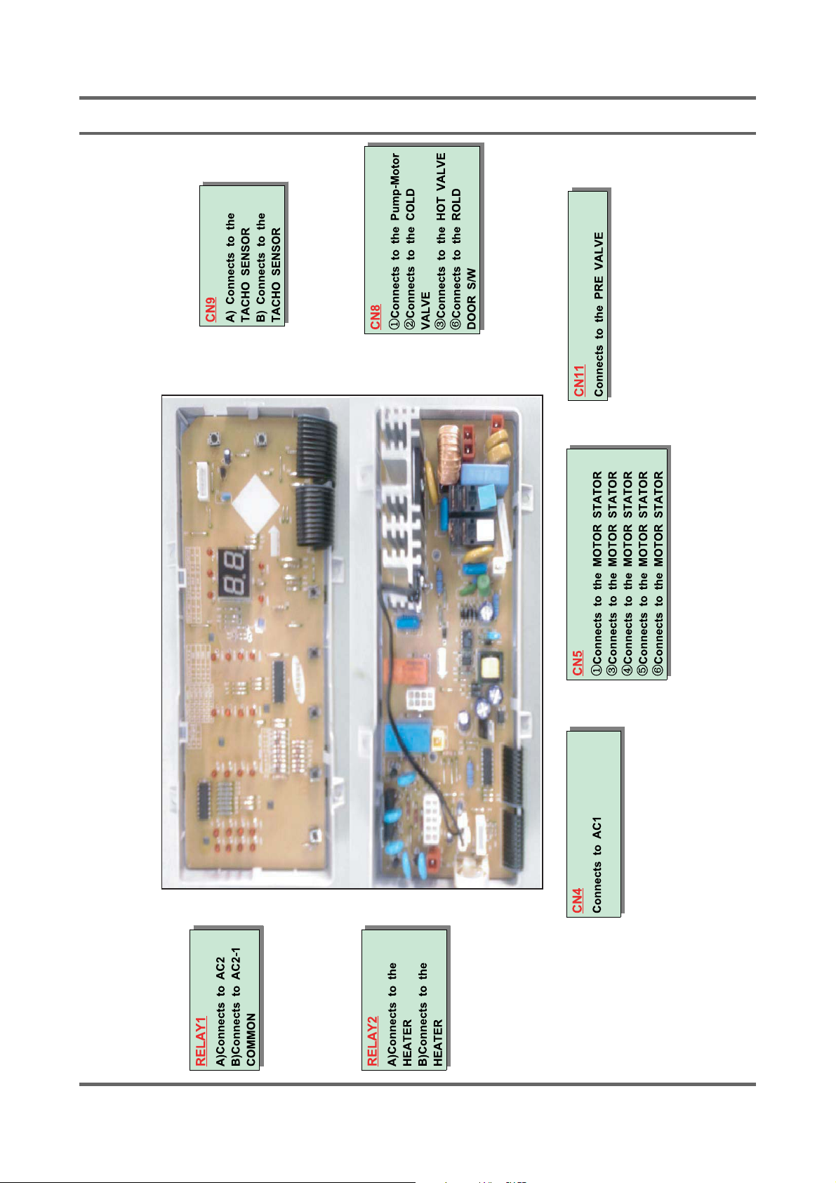
9-2. Connector & Relay Terminals Description (MAIN PCB)
51
Page 52
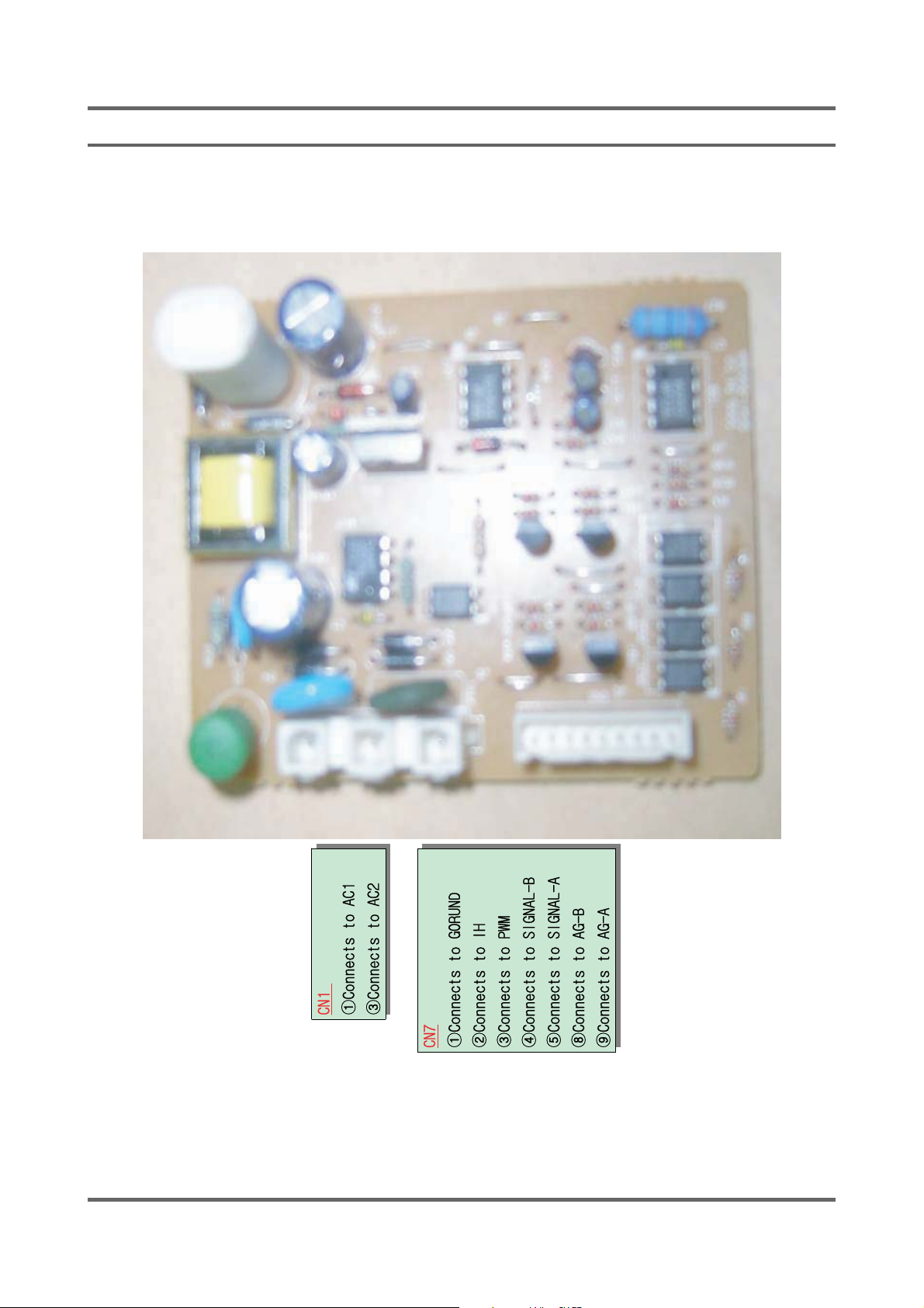
9-3. Connector & Relay Terminals Description (AG-KIT PBA Option)
Page 53
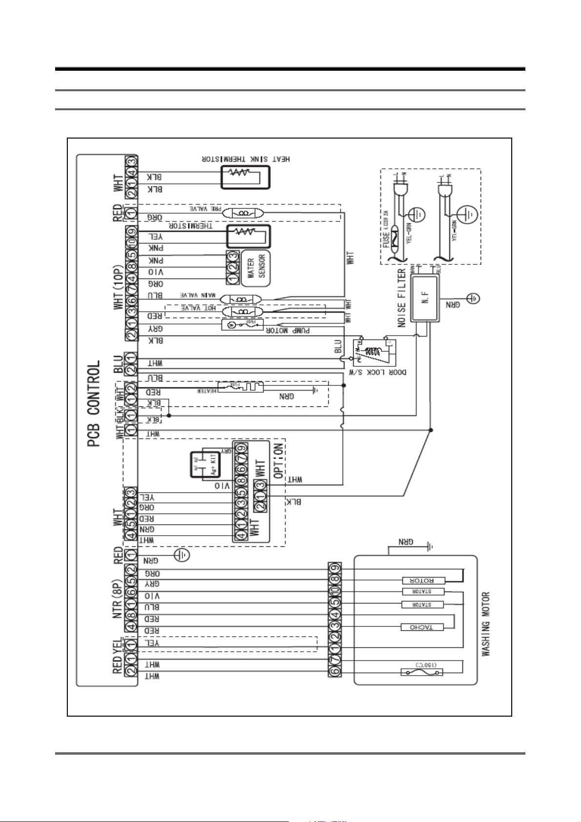
10. SCHEMATIC-DIAGRAM
10-1. ROLD (WF7450SAV)
53
Page 54
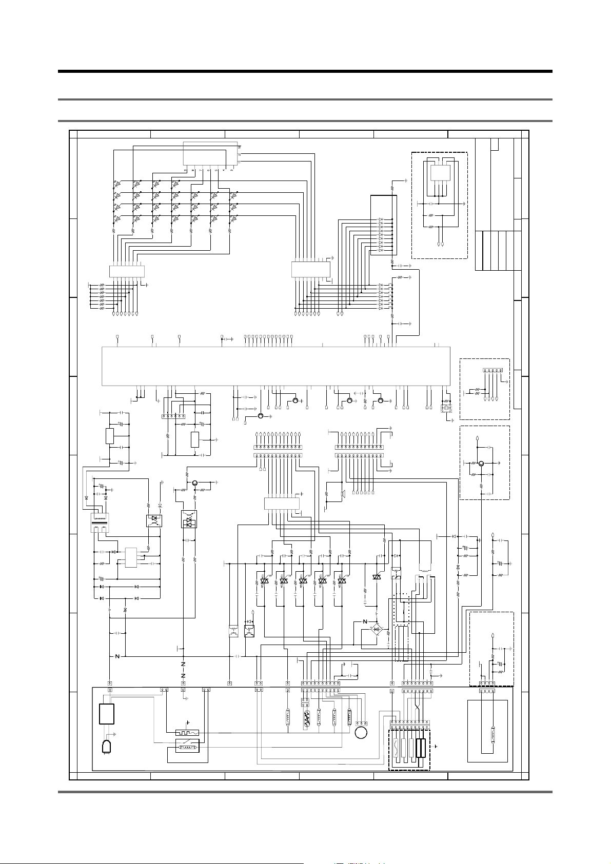
11. PCB CIRCUIT DIAGRAM
11-1. PCB CIRCUIT DIAGRAM
LED12
LED11
LED10
LED9
R9
ISP_TX
12
DGND
SMW250-06DW
R50
+5V
DGND
MTZJ11B
2
LTV817B
3
RELAY2
HEATER_RELAY
DSP1
330
51
51
MOTOR_CONTROL
ISP_RX11ISP_TEST
4
456
10K
+5V
PC2
+12V
ZNR2
ZNR1
GRN
DOOR SWITCH
B
CSD-4328G
LED16
LED15
LED14
LED13
R11
123
CN7
10K
R53
IC7
R32
4.7K
R31
4
1
10nFC5
100K
R18
14D182
14D911D
CN1
SET GND
CUT OFF
THERMAL
LED19
LED24
LED18
LED21
LED17
LED20
330
330
R12
R14
13
C28
13
TACHO
RESET
8
R45
4.7K
C25
100nF
CE6
1uF
7533
GND
DGND
IN OUT
100nF
C22
1K
TR2
MMBT3904
DGND
R29
47K
1K
R30
3
LTV814
2
100K
R20
+12V
OMIF-S-112LM
BLK
YDW236-01BLK
RELAY1
POWER_RELAY
A
8
SV50-R32
R3
7
O110O211O3
IC1
I17I26I35I4
R15
R13
+5V
R10
R8
R7
R4
R2
4.7k CHIP X 7
4.7K
5759616263
6
MICOM1
TMP86FS49FG
+5V
5
IC4
KA7805A
IN OUT
+8V
+12V
470uF
CE2
C4
42
3
DGND
100nF
UG2D
D25 UG2D
D24
5
6
7
8
LVT1
T-PJT
123
4
2.2nF
C2
D23
100K
R24
CE1
10uF
1N4007
D21
1N4007
D20
coil
L1
WHT
CN4
NOISE
FILTER
1
AC220-240V
L
N
SCHEMATIC DIAGRAM
A
330
58
20
20
AG-IH
C23
CE4
GND
C7
CE3
UF4007
PTC1
100nF
CM2
ZNR4
20D561
AC100-120V
LED4
LED8
LED3
LED7
LED2
LED6
LED5
SV50-R32
LED1
R5
R6
330
330
9
12
13
14
15
16
O4
O5
O6
O7
VCC
I7
GND
KID65003AP
4
3I52I61
8
DGND
60
23
7
DIGIT-LED
THERMISTOR_HS
AVDD
VAREF
VDD1VSS
5
19
18
+5V
100nF
470uF
100nF
470uF
DGND
100
ZD1
R26
1
PC1
4
100
DR54EN
R25
S2
3
S1
S4
2
7
C3
S3
BYP
8
100nF
1
IC3
TNY266P
1N4007
D18
1N4007
D19
270M
B
330
10nF
DGND
DOOR-SIG IN
ZERO CROSS
9
49
9
49
HEATER_RELAY
RY2
CC1
1
CN3
C
LED25
LED23
LED22
4041435961
383942
3839404142
SCAN-LED KEY
SCAN-LED KEY
SCAN-LED KEY
SCAN-LED KEY5SCAN-LED KEY
16
C26
10nF
DGND
C11
100nF
DGND
TR6
16
24
F1
123
C12
R40
150
C16
10nF
POWER_RELAY
1N4148
D1
POWER_RELAY
OMIF-S-112LM
RY1
680nF
2
GRN
This Document can not be used without Samsung’s authorization.
4.7K
R16
1N4148
100
4.7nF
C15
R37
4.7K
R1
SW6
SW7
SW5
SPS
SW4
SW3
SW2
SW1
SPS
1N4148
100
R34
C14
4.7nF
BIMETAL(LOCK)
55
54
OPTION
KEY_SCAN
DOOR_LOCK
SCAN-LED KEY
AG_SIG-A
DIGIT-LED
DIGIT-LED
56
14
57
KRC246S
DGND
14
57
DGND
+5V
+5V
DGND
300
R39
100nF
D26
2
1
1N4148
G
RY4
345
OMIH_SH_112L
MOTOR_CONTROL(10A)
OJ1
GSIB1560
R22
100
800, 1000RPM
CM3
1200, 1400RPM
100nF
HIGH RPM OPTION
INSERT
DELETE
YEL
CN6
WHT
123
6
3
7
1
7
6
3
1
TACHO
PROTECTOR
WASHING MOTOR
E
DGND
+5V
MEMORY(EEPROM)
DGND
DGND
DGND
AG_SIG-B
15
15
RY3
34567
JUMP
456
8
4
9
8
4
9
ROTOR
1
5
5
STATOR
10
10
STATOR
53
C13
R36
R33
EEPROM1
53
C9
7
2
2
IC5
2
EEPROM2
SCL52SDA
52
8
8
1
17
100nF
10K
10K
DIAL-A
+5V
8
7
VCC
A0
2
10
DIAL-B
RTE24012
100nF
CN5
6
5
WP
SDA
24LC04B
A2 SCL
VSS
A1
4
3
DGND
53
52
XIN
XOUT
2
3
+5V
1M
R46
X1
16MHZ
AG KIT
DGND
+5V
TACHO
C30
100nF
D27
1N4148
CE7
10uF
R41
D221N4007
47K
R23
R21
270K
R19
270K
DGND
F
C
586062
58596061626364
43
DIGIT-LED
DIGIT-LED
SCAN-LED KEY
CW/CCW
POWER_RELAY
HIGH_SPEED
DIGIT-LED
45
26
KRC246S
DGND
23
22
202122
23
45678
THERMISTOR_H
THERMISTOR_HS
1
2I23
I1
IC6
O1
O2
16
15
R38
10nF
TRIAC_1A
TRIAC2
VALVE_HOT
CN2
252627
14
R60
C32
DIGIT-LED
PWM_AG
37
25
26
19
I3
O313O412O5
620
DIGIT-LED
SCAN-LED KEY
46
37
4
5
I4
C34
150
10nF
TRIAC6
VALVE_PRE
IC2
63
64
DIGIT-LED
DIGIT-LED
DIGIT-LED
27
31
33
302951249
9
10
7
I5
I66I7
O6
O7
11
10
R51
10nF
R48
TRIAC_1A
C21
1
RED
CN11
PRE VALVE
18
O1
I1
1
TR4
28
1415161718
11
8
GND
VCC
9
620
+5V
17
16
O2
I2
2
3
KRC246S
27
13
12
KID65003AP
C19
150
10nF
TRIAC3
10
WHT
THERMISTOR
D
D
14
13
12
11
15
10
O4
I4
4
5
38
SCAN-LED KEY
36
50
36
DGND
O5
O6
O7
O8
GND
VCC
I5
I6
I7
I8
KID65783AP
9
6
7
8
+12V
39
41
42
40
6
P21
W_HEATER
DIGIT-LED
THERMISTOR_H
VALVE_HOT
222324
28
44
22
24
+12V
24
O3
I3
373635
DGND
F2
123
+12V
1K
R59
R42
C33 R61
SM2LZ47
+12V
620
10nF
C31
150
TRIAC_1A
10nF
TRIAC5
VALVE_MAIN
5
678
MAIN VALVE
R55
R58C29
4
3
PUMP MOTOR
BZ1
620
150
10nF
1
2
DGND
+12V
10nF
DOOR_UNLOCK(BIMETAL_LOCK)
9
43
28
47
23
C24
10nF
TRIAC_1A
TRIAC4
D_PUMP
CN8
DGND
TR3
KRC246S
48
202122
56789
4
WILL
AG_SIG-B
R47
620
+5V
DGND
C17
100nF
HOT VALVE
WATER SENSOR
1nF
C6
DGND
19
TACHO
1
293031
48
R27
1K
AG_SIG-A
R17
CM1
ZNR3
2
D17
D16
OPTION PART
D14
D12
D10
D8
D6
D4
D2
D3
D5
D7
D9
D11
D13
D15
313335
29
30
333435
32
D_PUMP
DOOR_COM
VALVE_PRE
VALVE_MAIN(COLD)
BUZZER
W/L SENSOR
21
47
TR1
47
48
20162514131549
161718
131415
10
11
AG-IH
PWM_AG
POWER_RELAY
C1
MT1
SM10LZ47
TRIAC1
MT2
180
100nF
COIL1
20D561
NV2-08730
BD1
3
E
1N4148 X 9
1N4148 X 7
DOOR_UNLOCK
12
F
A3
Size
CIS-MID NEW
[SMPS, FLASH MICOM]
Suwon-City, Gyeonggi-Do, Korea
416, Maetan-3Dong, Youngtong-Gu
SAMSUNG Electronics Co., Ltd.
TITLE:
OK
MYUNG_JU KIM
MYUNG_JU KIM
MFG ENGR CHK
R&D CHK
Drawn by
DOC CTRL CHK
Engineer
12345
CN10
DGND
4.7K
R52
R54
4.7K
AG-IH
PWM_AG
AG_SIG-A
AG_SIG-B
TACHO
10nF
C20
MMBT3904
TR5
R49
4.7K
DGND
R35
27K
C10
100nF
1K
R28
C8
100nF
THERMISTOR_H
C18
100nF
DGND
1K
R44
CE5
33K
THERMISTOR_HEATSINK
10uF
4.7K
R43
THERMISTOR_HS
C27
100nF
1K
R57
CE8
10uF
+5V
R56
10K
123
4
WHT
CN9
HEATSINK TERMISTOR
1
of
1
Sheet
8
Drawing Number
REVChanged by
7
QA CHK
16:30:00 P.M.
Time Changed
6
Saturday, August 15, 2005
Date Changed
4
DGND
3
DGND
2
1
54
Page 55
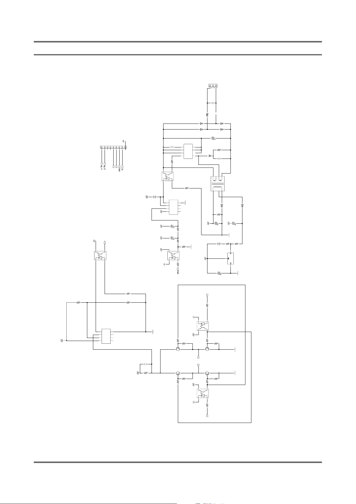
11-2. PCB CIRCUIT DIAGRAM(AG-KIT Option)
D
G
N
D
S
C
M
N
2
7
9
8
I
H
D
G
N
D
3
4
L
T
V
8
P
1
7
C
B
4
2
1
R
1
K
3
8
L
M
3
9
3
1
OA
VCC
2
-IA
OB
3
+IA
C
G
N
D
-IB
4
GND
+IB
W
6
5
4
3
1
2
B
2
5
0
-
0
9
W
H
T
S
S
i
i
g
g
n
n
a
a
l
l
_
_
A
B
C
G
N
D
1
N
4
7
5
1
4
R
.
3
7
K
2
R
0
2
K
4
I
C
2
8
7
6
5
1
8
V
C
1
0
7
0
n
F
C
G
N
D
2
R
7
2
7
C
1
0
1
0
n
F
R
1
2
0
0
0
3
4
L
T
V
8
P
1
7
C
B
5
2
1
IC1
KA2904
Z
D
2
C
G
N
D
C
G
N
D
C
G
N
D
C
G
N
D
8
1
OA
VCC
7
2
-IA
OB
6
3
+IA
-IB
5
4
GND
+IB
1
C
0
E
u
8
F
C
1
u
E
F
1
1
3
4
P
C
6
2
1
1
D
G
K
N
D
4
R
.
7
1
K
3
T
R
5
T
R
6
4
R
.
7
1
K
4
This Document can not be used without Samsung’s authorization.
9
C
0
N
0
1
1
9
W
S
-
0
3
W
H
T
1
C
0
6
n
F
L1
PTC1
JUMP
270M
1
BYP
2
S1
3
S2
EN
TNY266P
4
7
1
8
V
4
R
.
7
3
K
1
4
R
.
7
3
K
0
1
0
L
K
T
V
8
1
7
B
R
7
4
R
.
1
7
6
K
KSA928A-Y
KSA928A-Y
R
4
.
1
7
2
K
D
6
1N4007
D
7
1N4007
I
C
3
8
S3
7
S4
54
DR
UF4007
R
2
8
1
8
V
R
1
7
C
G
N
D
R
1
D
G
N
D
2
P
C
1
3
C
G
N
D
R
1
1
A
g
_
B
A
g
_
A
R
1
5
C
G
N
D
3
P
C
3
2
D
G
N
D
1
K
1
4
4
.
7
K
T
R
1
T
R
4
4
.
7
K
4
1
C
G
N
D
S
i
g
n
a
l
_
A
L
T
V
8
1
7
B
KSA928A-Y
L
T
V
8
1
7
B
R
6
1N4007
1N4007
1
C
0
E
u
4
F
1
0
0
K
D
2
2
.
2
N
F
4
3
5
6
4
C
7
E
0
1
u
3
F
1
N
4
7
5
1
1
0
u
F
KSA928A-Y
1
K
D
4
D
5
R
2
3
C
8
2
1
L
E
V
E
T
1
1
6
1
6
-
H
7
8
U
F
4
0
D
0
7
1
1
2
0
O
H
R
M
3
7
2
Z
2
D
0
3
C
E
9
4
R
.
9
7
K
4
R
.
1
7
0
K
U
F
D
4
3
0
0
7
C
G
N
D
4
C
7
E
u
1
F
0
+
1
2
V
1
R
R
0
3
3
0
3
6
K
I
C
A
4
7
8
1
8
1
8
V
+
1
2
V
+
1
2
V
S
i
g
n
a
l
_
B
Page 56
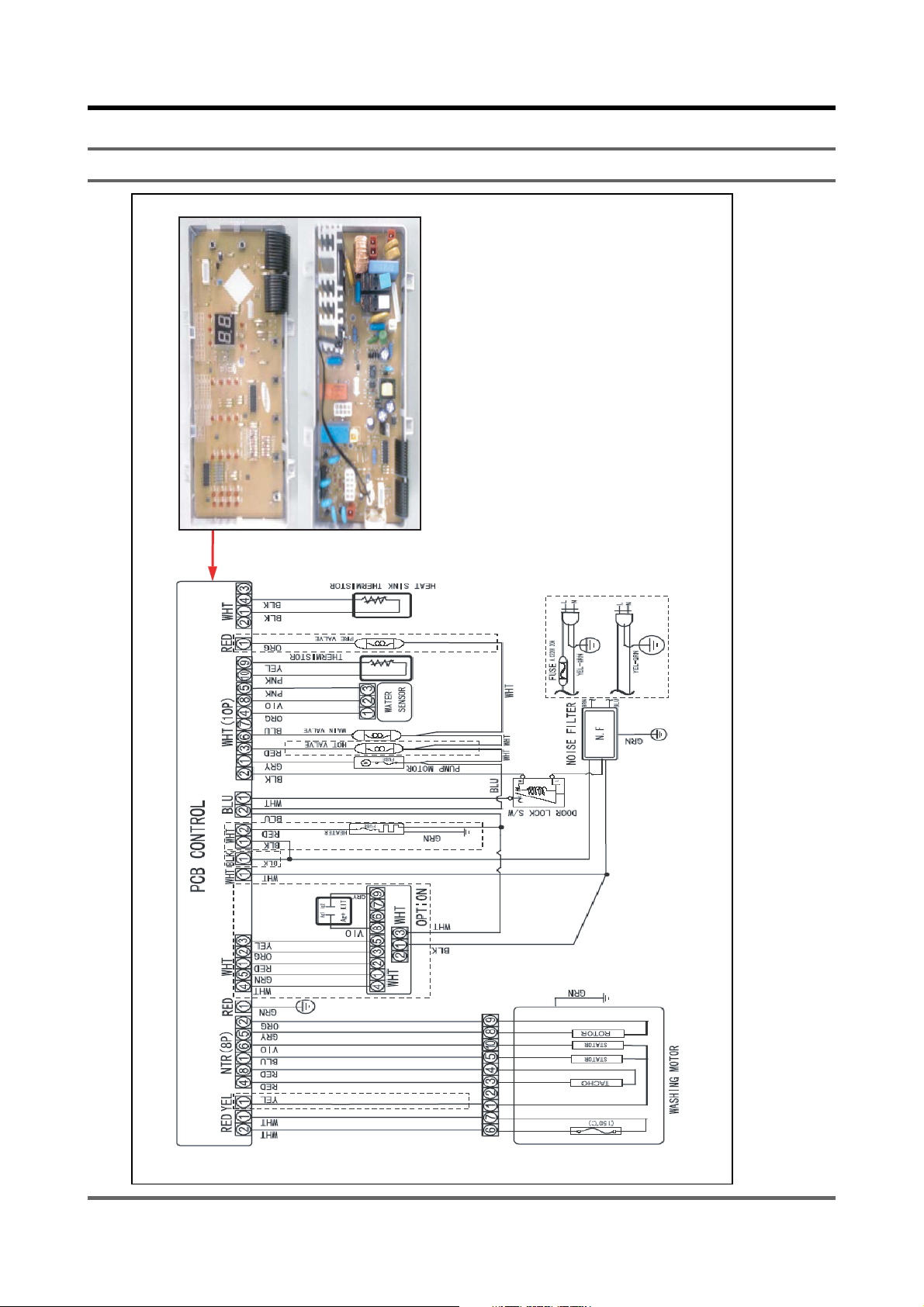
12. CIRCUIT DESCRIPTION
12-1.OVERALL SYSTEM
56
Page 57
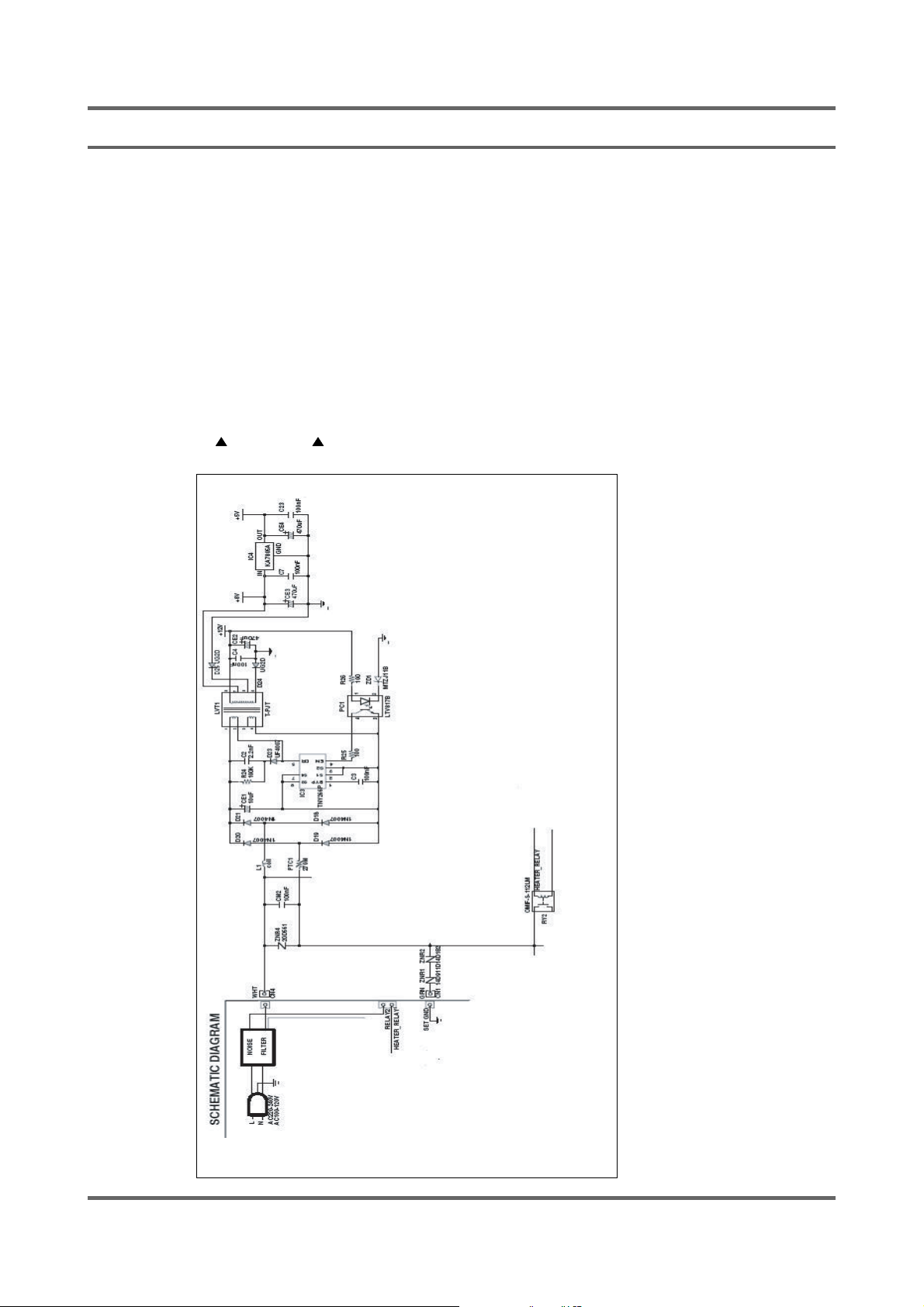
12-2.AC INPUT & POWER CIRCUIT
Function
Generates a required DC power of 12V
Description
or 5V in case of supplied or disconnected
AC power.
- When AC 220V is applied to D18~D21
it to DC 300V
- When DC 300V IS appliedto IC3
LVT1t to dC 12V. and dc 8v
through IC4(KA7805).
- The 8v is transformed to DC 5V
57
Page 58
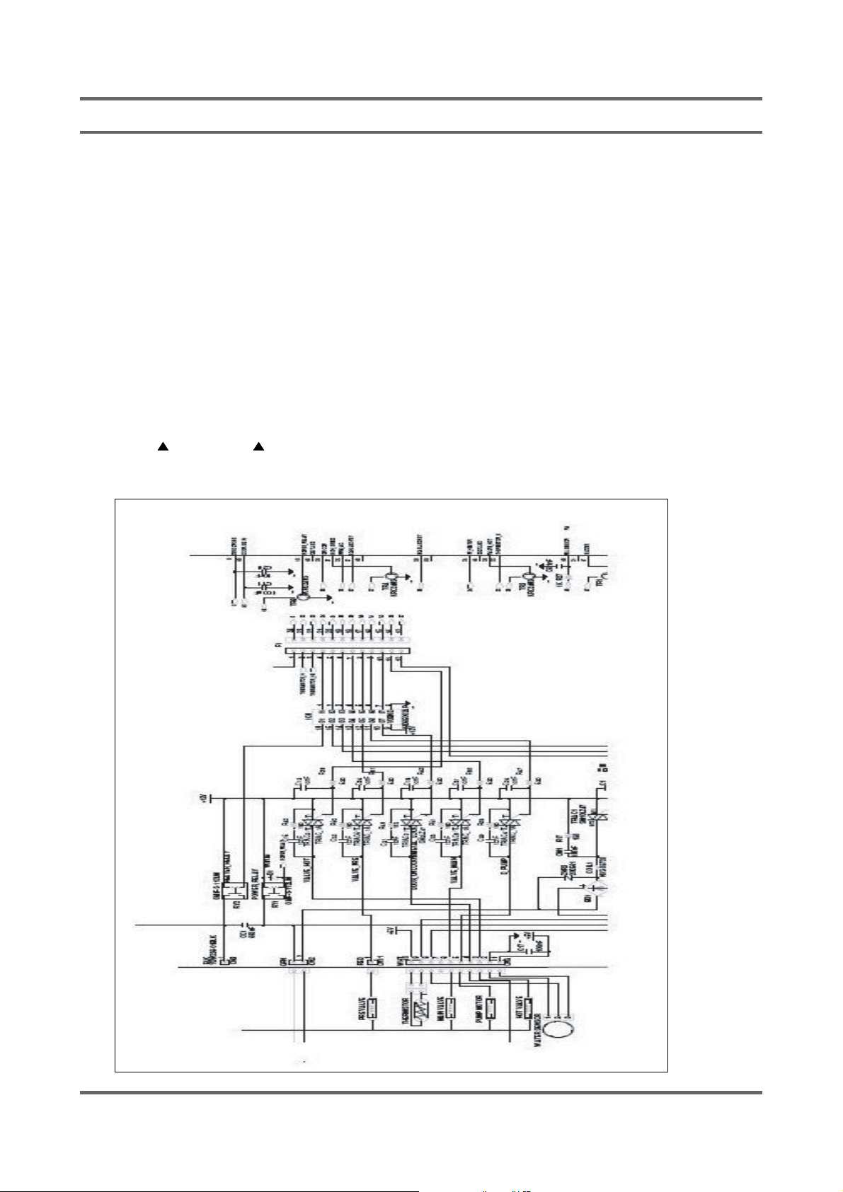
12-3.DRIVING SYSTEM CIRCUIT
Function
Controls each driving system (VALVE, DOOR
S/W, DRAIN-MOTOR) by turning RELAY or
TRIAC on/off.
Description
- MICOM outputs a high signal of 5V from pin
DOOR S/W) connected to CN6 turn on if
the TR14,15 are grounded this creates an
electric potential difference from the 12V that
- Then, IC6 pin10~16 areelectrically
grounded (0V).
-Whenpin#10to16aregrounded,and
# 29,30,31,32,34 of micom.
turns on RELAY 1,2,3,4 and TRIAC1,2,3,4,5,6
theyaresuppliedwithpower.
- The operating parts (VALVE, DRAIN-MOTOR,
58
Page 59
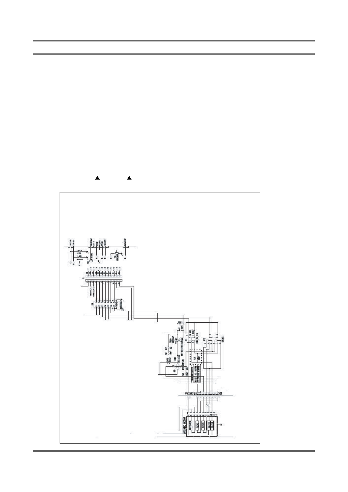
12-4.MOTOR CIRCUIT
Function
Description
that of the driving system.
(0V), TRIAC1 turns on.
unlocked. If unlocked, it does not apply
power to the motor even if TRIAC1 turns on.
the motor connected to CN4 is supplied with
power and drives CW (right direction).
will drive the motor CCW (reverse) as the
wiring is switched to CCW.
Supplies power to the motor and turns it
CW/CCW (Right / Reverse direction).
- The operation of TRIAC1 is the same as
- If the electric potential of R39 is grounded
- CN1 detects if the door is locked or
- If the door is unlocked and TRIAC1 turns on,
- Under such conditions, turning RELAY3 on
of the motor to one for higher driving.
- Turning RELAY4 on will switch the winding
59
Page 60
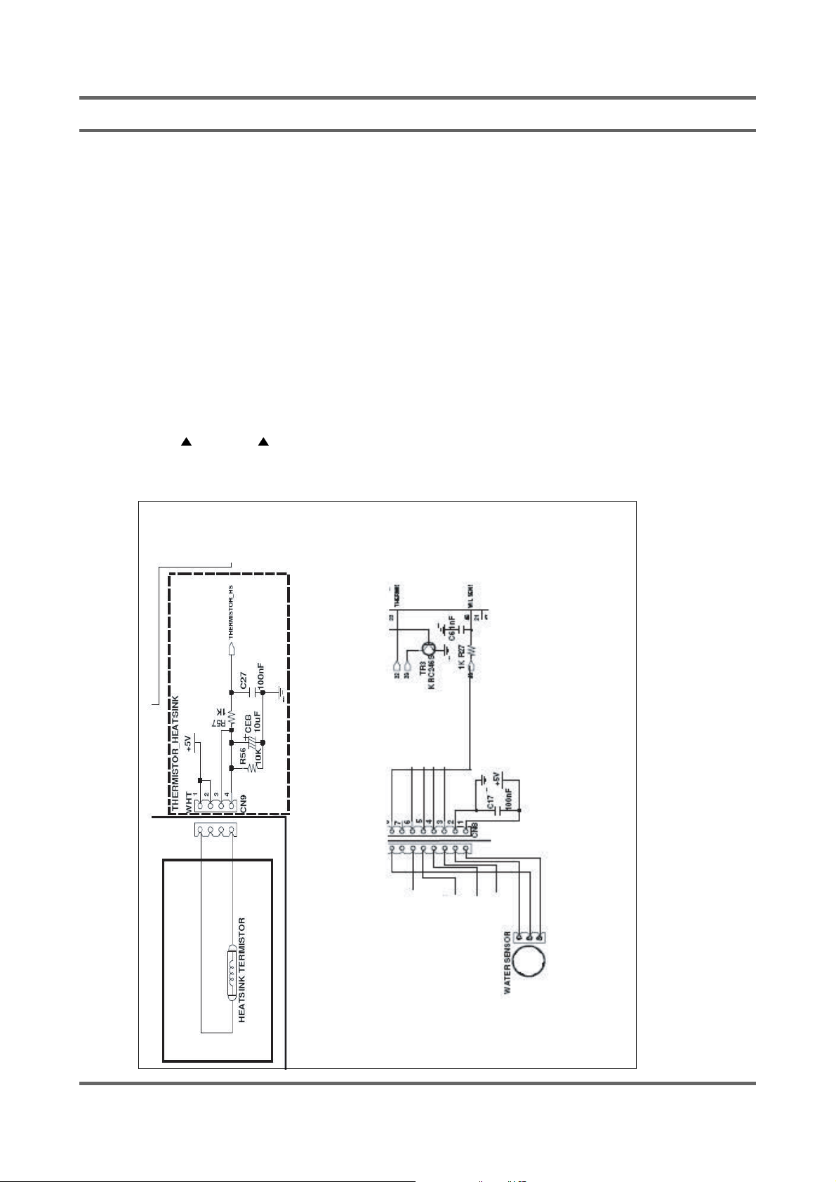
12-5.SENSOR DETECTION CIRCUIT
Function
Detects signals from the sensor and controls
the current system.
Description
- The water level sensor is connected to pin 8
of CN6.
- The frequency of the level sensor changes
accordingtothewateramountinthetub.
48 for detecting the water amount.
- Then, the frequency is input to MICOM pin
- The DHSEH sensor is connected to CN9 ;
according to the ambient temperature. The
- The resistance of the temp. sensor changes
changed resistance is applied to R56 and
R57.
decided according the temp. MICOM stores
- The voltage applied to R56 and R57 is
MICOM compares it to the pre-
the value.
defined one before detecting the current
- When voltage is applied to MICOM pins 23,
temp.
60
Page 61
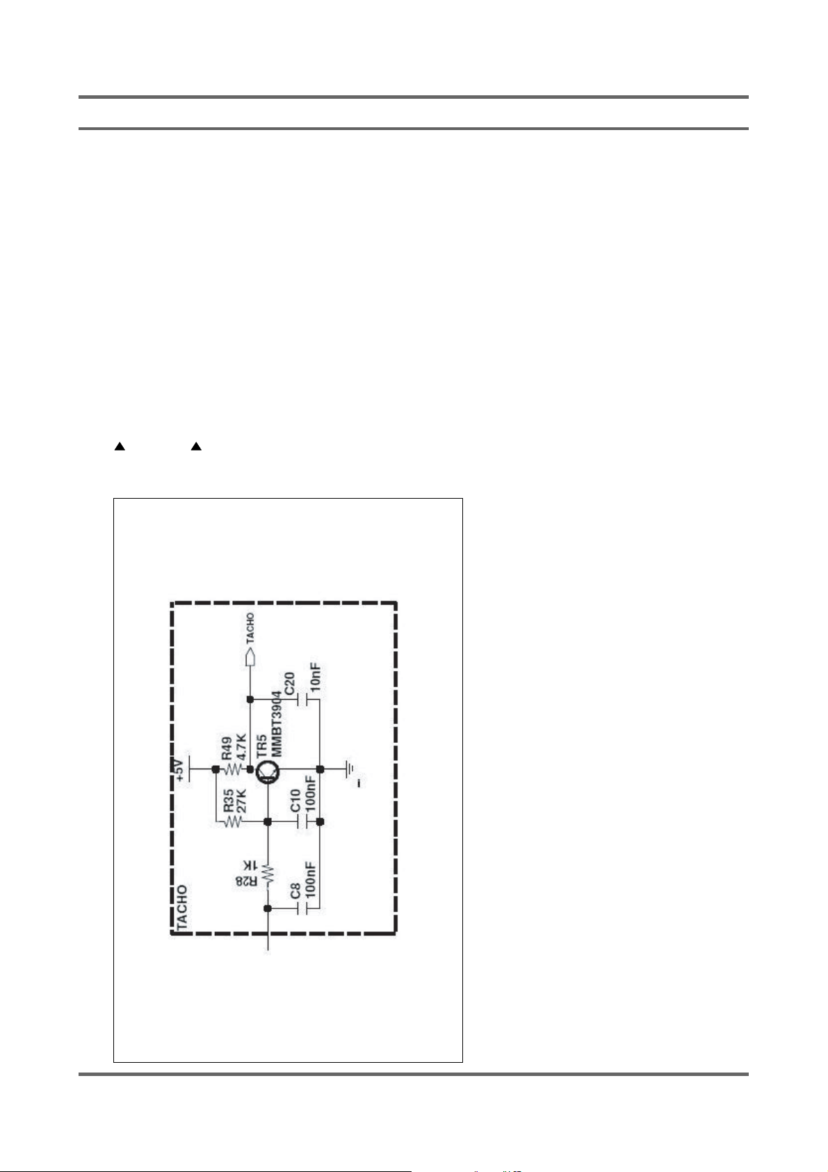
12-6.MOTOR TACHO INPUT SYSTEM
Function
Description
Detects the current RPM of the motor and
controls the output.
pin 1 of the CN5.
- The motor TACHO sensor is connected to
asquarewaveisappliedtopin1.
- According to the current RPM of the motor,
- The square wave that is input to TR5
BASE turns the motor on if high (5V), and
turns it off if low (0V). And this operation
will be inverted to TACHO NET for a clear
wave with no noise.
Then MICOM counts the frequency of the
input signal and detects the current RPM of
- The signal is applied to MICOM pin 13.
the motor.
61
Page 62
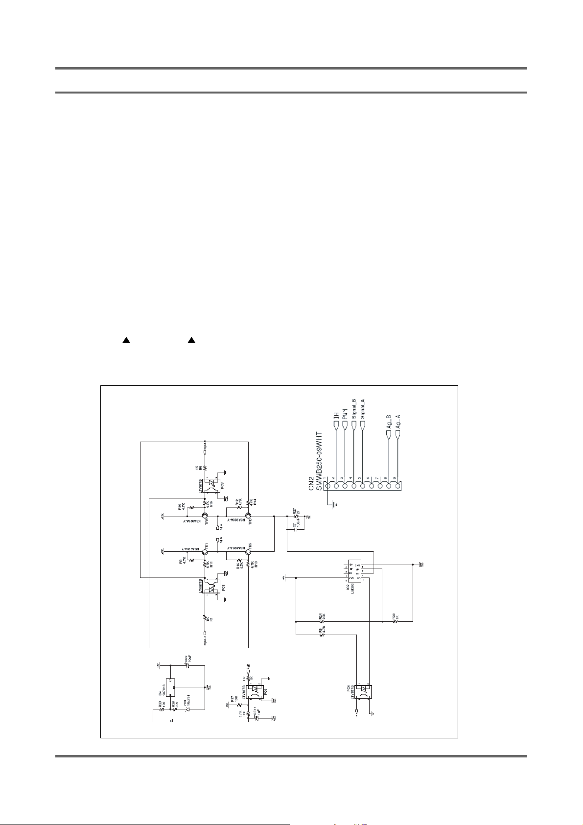
12-7.SILVER NANO SYSTEM(OPTION)
Function
Applies the electric current to the silver plate during
the water supply and uses the silver water to
Description
perform the bacteria-free or sterilization processes.
the system.
- Selects the silver nano feature to operate
and AG_A.
- Supplies water to the two silver plates AG_B
Then, SINAL_A and SIGNAL_B output a
high signal of 5V.
for 15 seconds outputting a high signal of 5V.
SIGNAL_A output turns TR1 and TR6 on to
generate a potential difference between the 12V
and the grounding for causing the current to flow.
SIGNAL_B output turns TR4 and TR5 on to
generate a potential difference between the 12V
and the grounding for causing the current to flow.
the resistance of R27.
- Both SIGNAL_A and SIGNAL_B repeat this
- The flowing current is transformed to a voltage by
for detecting and controlling the flowing current.
- Then, the voltage is applied to IC1 pin 2 and used
62
 Loading...