

Samsung WA5451ANW-XAA User Manual
Model:
WA5451ANW/XAA
Fast Track Troubleshooting
IMPORTANT SAFETY NOTICE – “For Technicians Only” This service data sheet is
intended for use by persons having electrical, electronic, and mechanical experience
and knowledge at a level generally considered acceptable in the appliance repair trade.
Any attempt to repair a major appliance may result in personal injury and property
damage. The manufacturer or seller cannot be responsible, nor assume any liability for
injury or damage of any kind arising from the use of this data sheet.
SUPPORT INFORMATION
Publication # nwWA5451 Creation Date 09/22/2011
Training — Plus One http://my.plus1solutions.net/clientPortals/samsung/
Help — GSPN http://service.samsungportal.com/
Samsung Product Support TV http://support-us.samsung.com/spstv/ho wto.jsp
Customer information videos and chat programs. Programs for Fridges, Laundry, Ranges & D/W
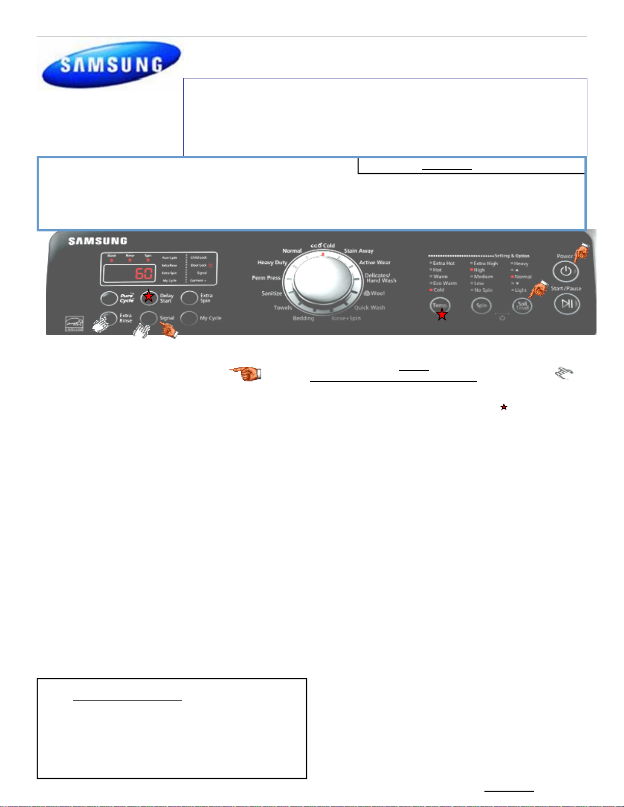
Service Mode:
Quick Test Mode
To enter press Soil, Signal, & Power
simultaneously with the power off.
1. All LED’s light up and the washer beeps as it
enters the Quick Test Mode.
2. The unit displays the software version for a
second then clears the EEprom.
3. After the displaying the software version, LCD
will display Model information. If EEEE is displayed
the PCB assembly is defective.
4. When the version is displayed, turn the Jog-Dial
so that the version disappears. Press the following
keys to test the various components
Press Temp Key to cycle through the Water Valve test
(Door does not need to lock) in this order: Cold, Bleach,
Hot, Rinse (Softener), & 3 cold valves then off.
Press Spin Key to test Circulation/Drain Pump.
Press Soil Level Key to test Water Heater
Press Signal Key to test the Door Lock/Unlock circuit
When either Test or Spin is displayed on the LCD, press
Start/Pause key to conduct the motor test.
In Test mode, you can test the clockwise and counter-
clockwise movement of the motor. However, the water
level must satisfy the heater water level (24300) to enter
Test mode.
In Spin mode, you can test the motor at a high rpm. The
RPMs will also be displayed
Continuous Run Mode:
1. Press Delay Start + Soil Level Key
(Normal User Mode) .
2. Once in Continuous Run Mode, The seven segments will no longer
display “0000” and will alternate between displaying the number of cycles of the completed course and the remaining time of the course.
3. The Continuous Run Mode will repeat the previous cycle until continuous run mode is cancelled by pressing the same button combination for
7 sec.
for 7 sec during Power On State
This mode allows more detailed operation tests and troubleshooting, to enter press
Signal & Extra Rinse
simultaneously with the power on.
While in Service Mode the following tests can be performed:
Quick Spin Test = Delay Start & Temp: This accelerates
the drum motor from 0 to maximum RPM over a few
minutes. Note: Stay with the washer during this test, out of
balance detection may be bypassed.
Press the Start/Pause button during the test to hold its spinning
speed for 10 minutes before going back to Quick Spin Test
Cycle Count = Press Signal key to view times the unit was used
Soft Ware # = Press Soil key to see the software version info
Fast Time Down = Press Temp key to advance to next cycle
Fault Code Test = Press the Spin button to view the
stored fault codes – then turn Jog Dial to view error codes
(Push Start/Pause while the code is displayed to view the number of cycles since the error occurred)
Peripheral (Main PCB) input Tests
1. Select Extra Rinse. Then turn the Jog-Dial so that the Normal
LED is turned on. The Water Temperature will be displayed in
Centigrade
2. Select Extra Rinse. Then turn the Jog-Dial so that the Heavy
Duty is turned on. The water temperature will be displayed in
Fahrenheit.
3. Select Extra Rinse. Then turn the Jog-Dial so that the Perm
Press LED is turned on. The door status will be displayed (OP if
open, CL if closed).
4. Select Extra Rinse. Then turn the Jog-Dial so that the Sanitize LED is turned on. The door lock Switch status will be dis-
played (UL if unlocked, Lo if locked).
5. Water Frequency/Water Sensor Testing Select a cycle &
start the washer, enter Service Mode & press Extra Rinse.
Turn the Jog Dial so that the Bedding LED is turned on. Next,
press the Start/Pause Key. The Water Frequency will be displayed. The frequency will change as the unit fills
# nwWA5451
09/22/2011

# nwWA5451
09/22/2011

Washer Connector Checks WA5471
CN2 Interface
1 Standby (S/BLU)
2 TX (VIO)
3 -RX (BLK)
4 Reset (BRN)
5-6 5vdc (Gry-Pnk)
CN3
1-2 Door Lock - (Blk-Brn)
4 Unlock Contact - (BLU)
5 Lock Contact - (RED)
6 Reed Switch - (GRN)
7 5VDC (WHT)
7-6 12vdc (Org-Pnk)
8 EMG - (YEL)
9 Power On (WHT)
10 Water Level (BLU)
11 Sub Reed (Red)
CN1
1-4 5vdc (Red – Grn)
2 Hall – B (GRY)
3 Hall – A (BLU)
4 GND - (BLK)
5 Clutch Hall – IC (WHT)
CN4 120vac
2-(CN6-3) Bleach Valve (Gry-Blk)
3-(CN6-3) Cold Valve (Blu-Blk)
4-(CN6-3) Hot Valve (Red-Blk)
RY13 Relay
1 Heater (Red)
2 AC Neutral (Wht)
5-(CN6-3) Rinse (Softener) Valve (Wht-Blk)
6 Clutch Contact (VIO)
7-(CN6-3) Cir. Pump (Yel-Blk)
8-(CN6-3) Clutch Mtr (Brn-Blk)
9-(RY12-2) Drain Pump (Pnk-Wht))
CN8
1 Motor Pwr U Phase (Red)
2 Motor Pwr V Phase (Wht)
3 Motor Pwr W Phase (Blu)
CN7
1 Reactor Connector Port (WHT)
2 Reactor Connector Port (WHT)
CN6
1 AC Neutral (Wht)
3 AC Line Common (Blk)
RY12 Relay
1 AC Line out (WHT)
2 AC Line (BLK)
A/C Power Check Test 1 Test 2
Relay RY12 (Pwr Relay) Pin 2 (Black) and RY13
(Heater Relay) Pin 2 (White)
Heater Relay Check Test 1 Test 2
Relay RY12 (Pwr Relay) Pin 1 (White) and RY13
(Heater Relay) Pin 1 (Red)
Hall Sensor Check Test 1
Voltage at Pin #4 (BLK) and #3 (BLU) of CN1
Voltage at Pin #4 (BLK) and #2 (GRY) of CN1
D-D Motor Check Test 1
Connector CN8 Pin 1 (Red), Pin 2 (White) and Pin 3
(Blue)
Clutch Motor Test 1
Connector CN4 PIN #8 (Brn) and CN6 PIN #3 (Blk)
Test 2 resistance between clutch motor terminals
Pin #3 (BLK) of CN6 and Pin #7 (YEL) of CN4
Plugged in 120VAC power on or off
120VAC with the Heater On and 0VAC
with the Heater off
Manually spin the drum to see the voltage change, Power On
0Vdc or 3.75Vdc
Power Off ~18 across Pins 1-2, Pins 13, & Pins 2-3
Power Off ~2 k across CN4 PIN #8
(Brn) and CN6 PIN #3 (Blk)
120VAC with the Mtr On and 0VAC Off
Test 1
Power on: CN6 1 (White -2
(Black) 120VAC
Power Off, heater resistance is
~12
Voltage at Pin #4 (BLK) and #1
(RED) of CN1 = 5VDC
N/A
Violet/Black – Brown = 0
Violet/Black – Black = ~2K
Brown – Black = ~2K
Resistance Pin #3 (BLK) of CN6
to Pin #7 (YEL) of CN4 = ~20
Test 2
Test 2
Test 2
Test 2
# nwWA5451
09/22/2011
 Loading...