

Page 1
Samsung Electronics 5-1
5. Schematic Diagrams
5-2
5-3
5-4
5-5
5-6
5-7
5-8
5-9
5-10
5-11
5-12
5-13
3 Block Identification of Main PCB - - - - - - - - - - - - - - - - - - - - - - - - - - - - - - -
5-1 S.M.P.S./Power (120 Voltage - 1) - - - - - - - - - - - - - - - - - - - - - - - - - - - - - -
5-2 S.M.P.S./Power (120 Voltage - 2) - - - - - - - - - - - - - - - - - - - - - - - - - - - - - -
5-3 S.M.P.S./Power (Free Voltage - 1) - - - - - - - - - - - - - - - - - - - - - - - - - - - - -
5-4 S.M.P.S./Power (Free Voltage - 2) - - - - - - - - - - - - - - - - - - - - - - - - - - - - -
5-5 Logic - - - - - - - - - - - - - - - - - - - - - - - - - - - - - - - - - - - - - - - - - - - - - - - - -
5-6 Audio/Video - - - - - - - - - - - - - - - - - - - - - - - - - - - - - - - - - - - - - - - - - - - -
5-7 Hi-Fi/MTS - - - - - - - - - - - - - - - - - - - - - - - - - - - - - - - - - - - - - - - - - - - - - -
5-8 TM-Block/Input-Output - - - - - - - - - - - - - - - - - - - - - - - - - - - - - - - - - - - -
5-9 Display - - - - - - - - - - - - - - - - - - - - - - - - - - - - - - - - - - - - - - - - - - - - - - -
5-10 Remote-Control (Multi-TV) - - - - - - - - - - - - - - - - - - - - - - - - - - - - - - - - -
5-11 Remote-Control (VCR Only) - - - - - - - - - - - - - - - - - - - - - - - - - - - - - - - - -
SCHEMATICS APPLICATION MODELS
S.M.P.S./Power (120 Voltage-1)
VR8809/8709/8609/8509/5709/5609/5509/3609
VR8809C/8769C/8719C/8609C/8509C/5809C/5709C/5609C/5509C/3609C
SV-C120UM/C70UM/C60UM/C100UP/C50UP
S.M.P.S./Power (120 Voltage-2)
VR8459/8409/5459/5409/3409/8459C/8409C/5459C/5409C/3409C
SV-C95UM/C45UM
S.M.P.S./Power (Free Voltage-1)
SV-C151P/C142P/C141P/C123P/C122P/C106P
SV-C105P/C63P/C61P/C60P/C56P/C55P/C52P/C25P/22P
S.M.P.S./Power (Free Voltage-2)
SV-C90P/C45P/C40P/C15P/SP-C15P
Page 2
Schematic Diagrams
5-2 Samsung Electronics
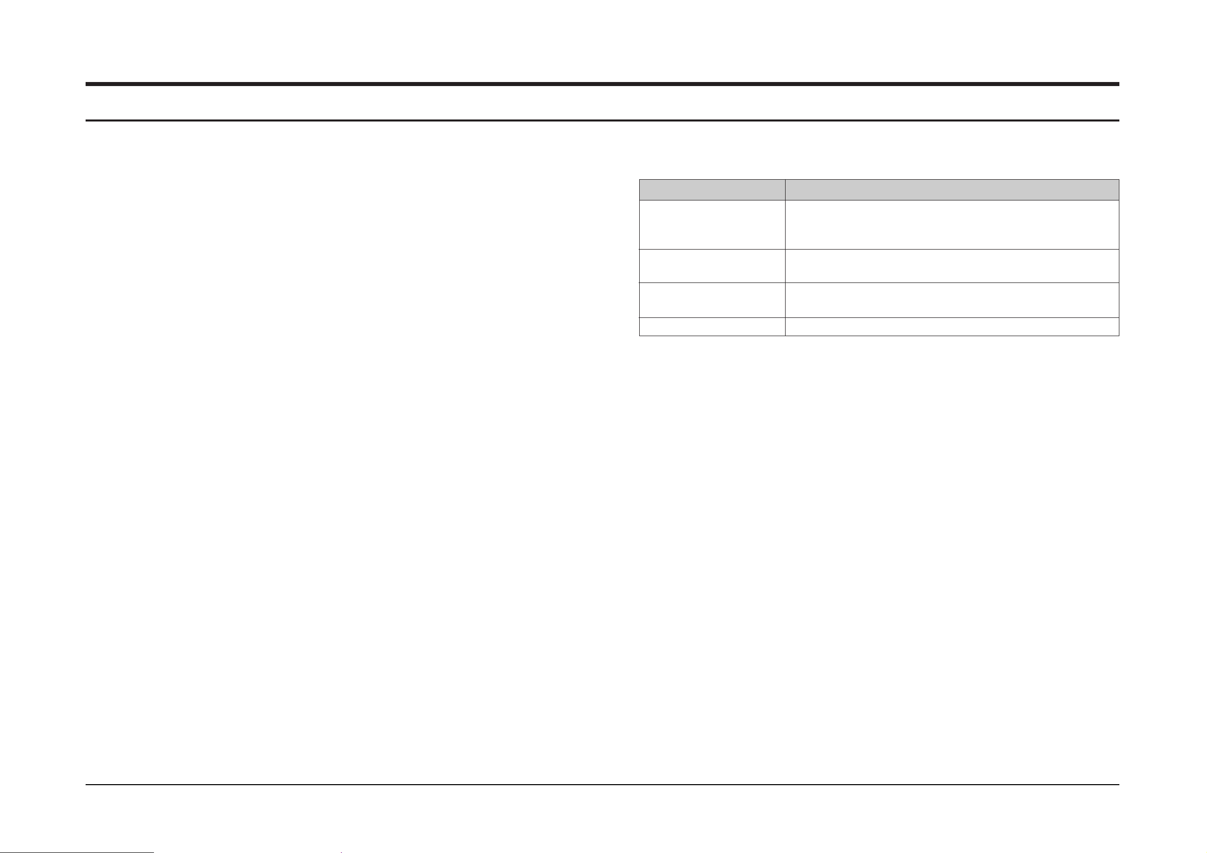
For schematic Diagram
- Resistors are in ohms, 1/8W unless otherwise noted.
Note
Special note :
Most semiconductor devices are electrostatically sensitive and therefore require the special handling techniques described under the
“electrostatically sensitive (ES) devices” section of this service manual.
Note :
Do not use the part number shown on this drawing for ordering. The correct part number is shown in the parts list (may be slightly different
or amended since this drawing was prepared).
Important safety notices :
Components identified with the mark have the special characteristics for safety. When replacing any of these components.
Use only the same type.
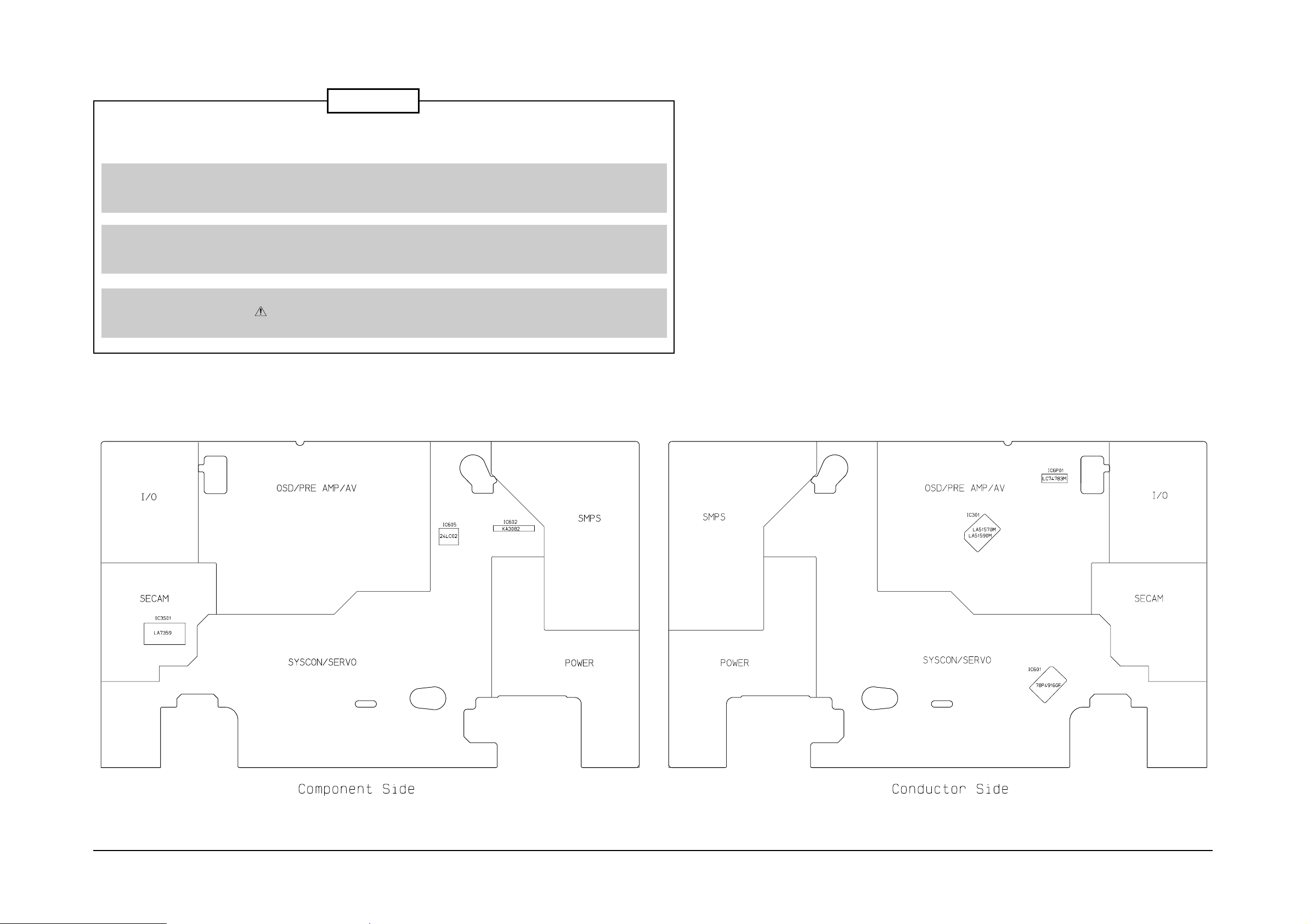
3 Block Identification of Main PCB
Page 3
Schematic Diagrams
Samsung Electronics 5-3
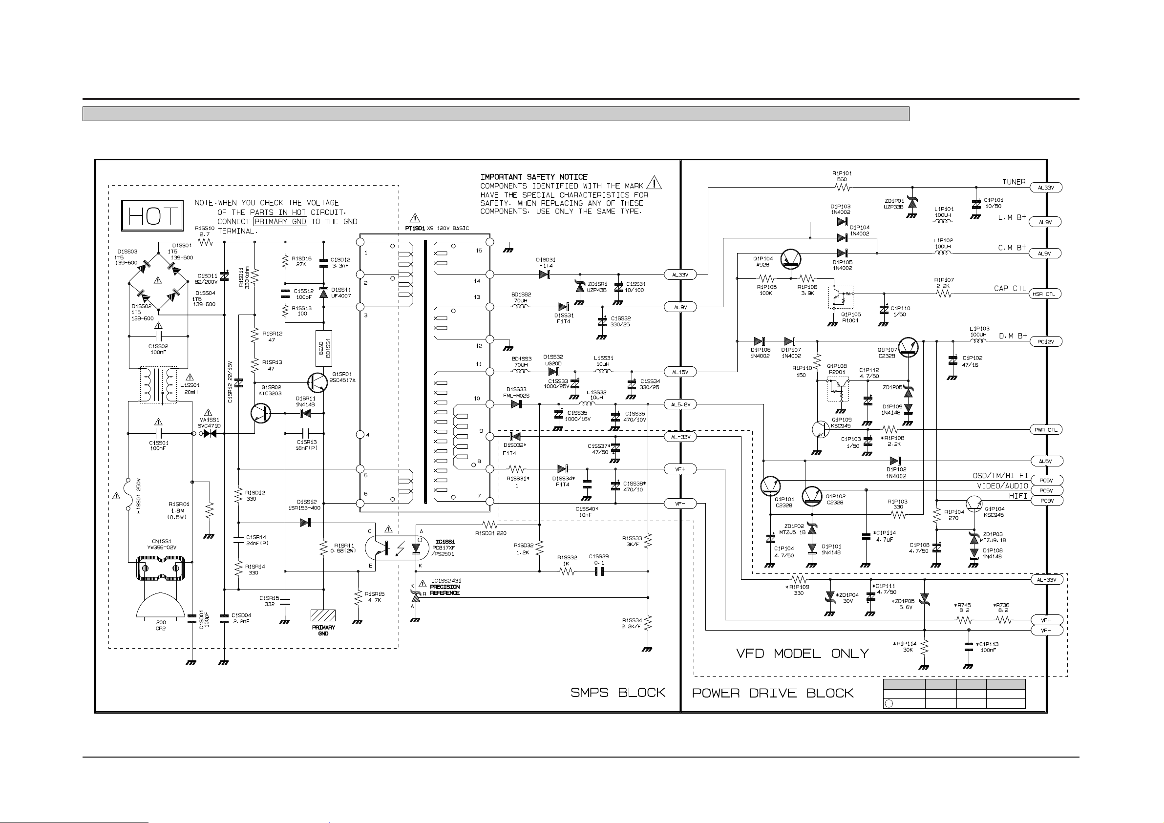
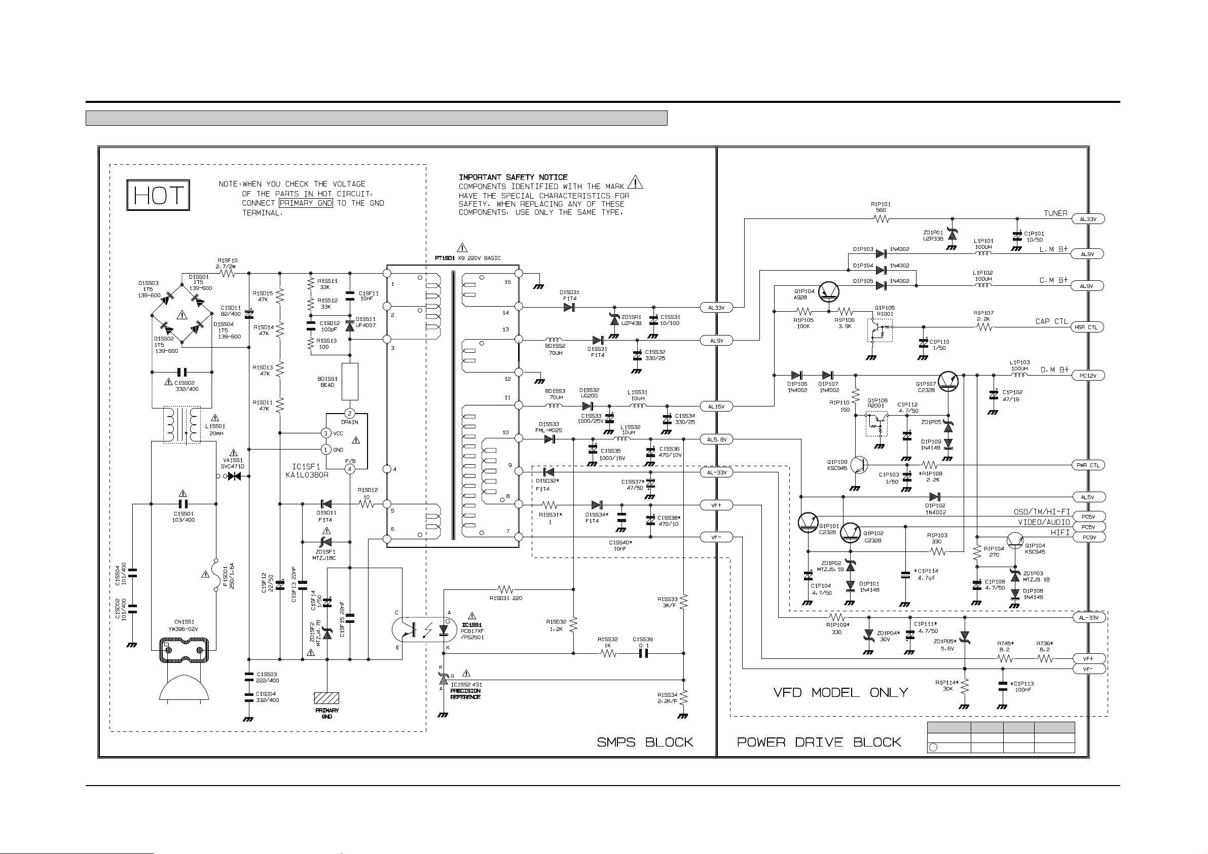
5-1 S.M.P.S./Power (120 Voltage - 1)
MAIN PCB C1P113 C1P114 R1P108
No Marking Addition Delete R-CARBON
A Marking Delete Addition R-CHIP
Application Models ; VR8809/8709/8609/8509/5709/5609/5509/3609/8809C/8769C/8719C/8609C/8509C/5809C/5709C/5609C/5509C/3609C/SV-C120UM/C70UM/C60UM/C100UP/C50UP
Page 4
Schematic Diagrams
5-4 Samsung Electronics
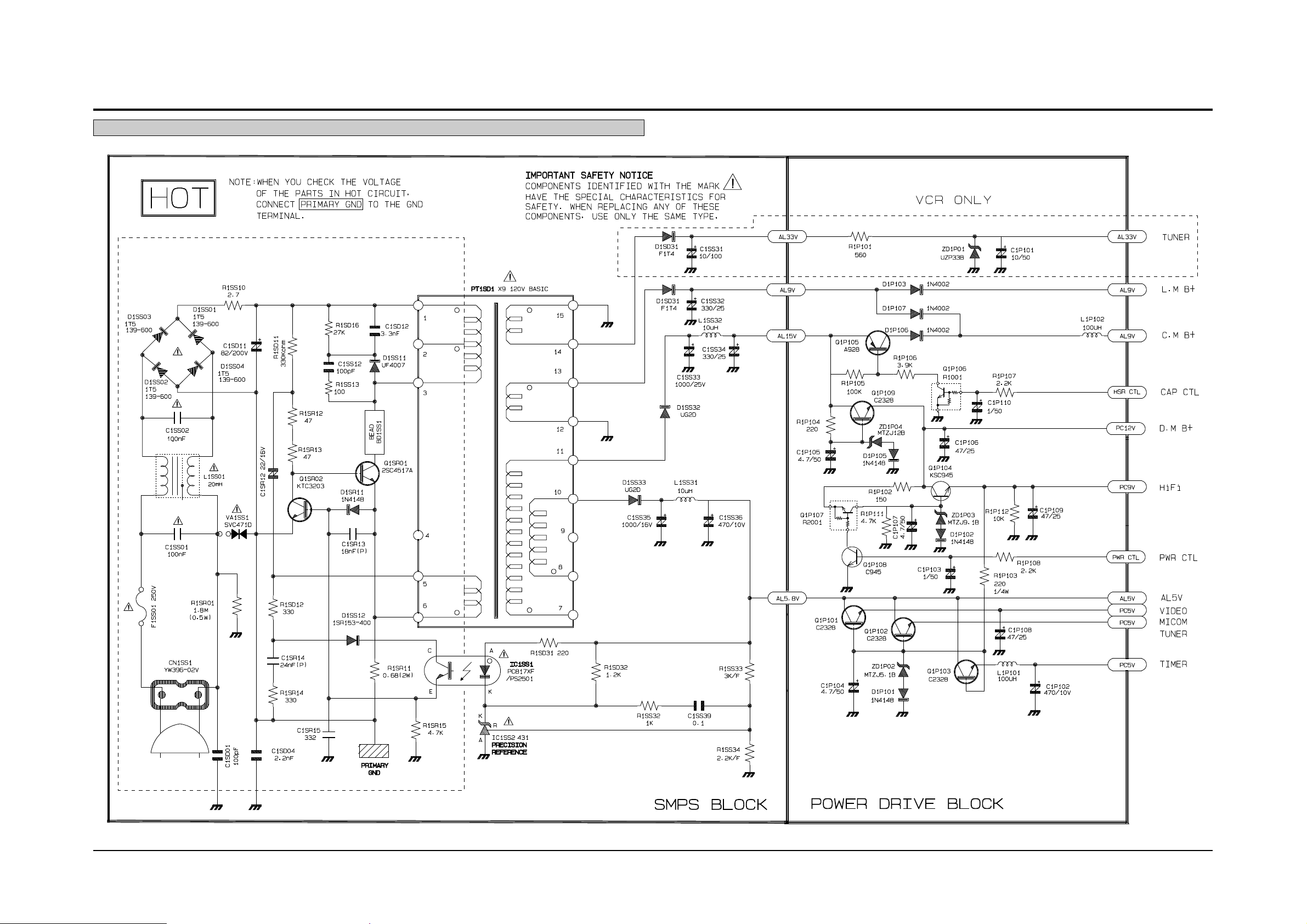
5-2 S.M.P.S./Power (120 Voltage - 2)
Application Models ; VR8459/8409/5459/5409/3409/8459C/8409C/5459C/5409C/3409C/SV-C95UM/C45UM
Page 5
Schematic Diagrams
Samsung Electronics 5-5
5-3 S.M.P.S./Power (Free Voltage - 1)
MAIN PCB C1P113 C1P114 R1P108
No Marking Addition Delete R-CARBON
A Marking Delete Addition R-CHIP
Application Models ; SV-C151P/C142P/C141P/C123P/C122P/C106P/C105P/C63P/C61P/C60P/C56P/C55P/C52P/C25P/22P
Page 6

Schematic Diagrams
5-6 Samsung Electronics
5-4 S.M.P.S./Power (Free Voltage - 2)
Application Models ; SV-C90P/C45P/C40P/C15P/SP-C15P
Page 7

Schematic Diagrams
Samsung Electronics 5-7
SW603
MAIN PCB D605 IC605 R691
No Marking Addition Delete Delete
A Marking Delete Addition Addition
5-5 Logic
Page 8

Schematic Diagrams
5-8 Samsung Electronics
5-6 Audio/Video
Page 9

Schematic Diagrams
Samsung Electronics 5-9
5-7 Hi-Fi/MTS
Page 10

Schematic Diagrams
5-10 Samsung Electronics
5-8 TM-Block/Input-Ouput
Page 11

Schematic Diagrams
Samsung Electronics 5-11
LED - MODULE
LED - LAMP
5-9 Display
Page 12

Schematic Diagrams
5-12 Samsung Electronics
5-10 Remote-Control (Multi-TV)
Page 13

Schematic Diagrams
Samsung Electronics 5-13
5-11 Remote-Control (VCR Only)
Page 14

5-14 Samsung Electronics
MEMO
 Loading...