

Samsung AS12A2VC, AS09A2VA, US12A2VC, US09A2VA, US07A2VA Service Manual
...
ROOM AIR CONDITIONER
INDOOR UNIT
AS12A2VC
AS09A2VA
AS07A2VA
SERVICE
OUTDOOR UNIT
US12A2VC
US09A2VA
US07A2VA
Manual
CONTENTSAIR CONDITIONER
1. Installation
2. Disassembly and Reassembly
3. Troubleshooting
4. Exploded Views and Parts List
5. Refrigerating Cycle Block Diagrams
6. Wiring Diagrams
7. Schematic Diagrams
E DB68-00040A(3)
1. Installation
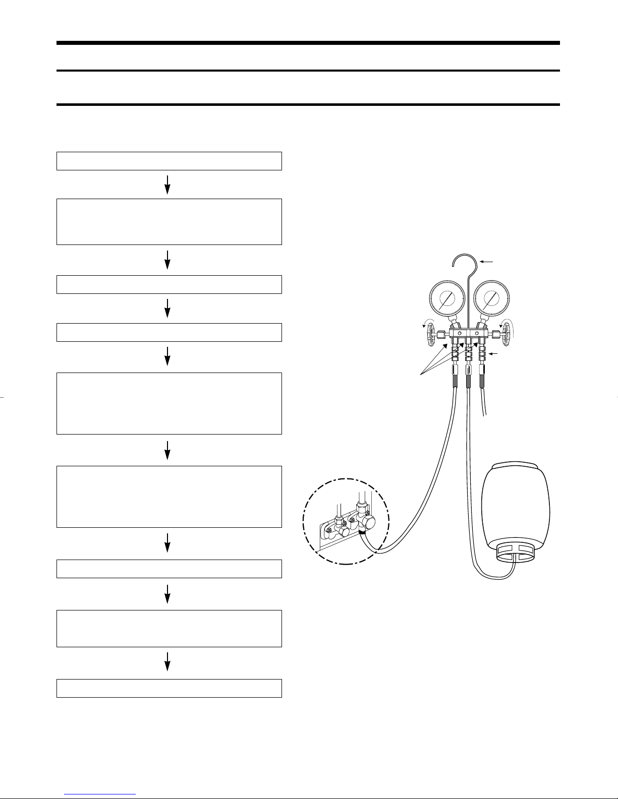
1-1 Refrigerant Refill Procedure
Refill an air-conditioner with refrigerant when refrigerant has been leaked at installing or using
1. Purge air(for new installation only).
2. Turn the 3-way valve clockwise to close, connect the
pressure gauge(low pressure side) to the service valve,
and open the 3-way valve again.
Suspension hook
3. Connect the tank to refill with Refrigerant
4. Set the unit to cool operation mode.
5. Check the pressure indicated by the pressure gauge(low
pressure side).
* Standard pressure is should be 64~78kg/cm
reqular, high operation mode.
6. Open the refrigerant tank and fill with refrigerant until
the rated pressure is reached.
* It is recommended not to pour the refrigerant in too
quickly, but gradually while operating a pressure valve.
7. Stop operation of the air conditioner.
2
in a
Compound
gauge
For mounting
other and of
hose when
not in use
High
pressure
gauge
Hand
wheel
Finger tight
fittings
Connected to
high pressure
side
Charging
line
R-22
8. Close the 3-way valve, disconnect the pressure gauge,
and open the 3-way valve again.
9. Close the cap of each valve.
1
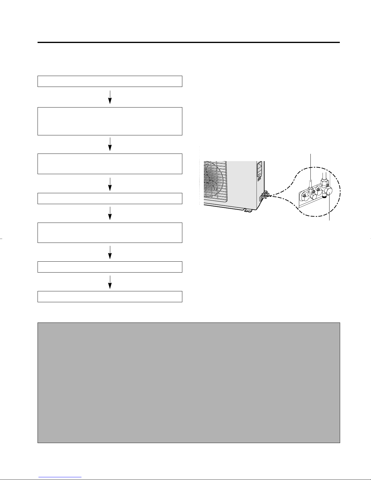
1-2 “Pump down” Procedure
Pump down' shall be carried out when an evaporator is replaced or when the unit is relocated in
another area.
1. Remove the caps from the 2-way valve and the 3-way valve.
2 Turn the 3-way valve clockwise to close and connect a pres-
sure gauge(low pressure side) to the service valve, and open
the 3-way valve again.
2-Way Valve
3. Set the unit to cool operation mode (Check if the compressor
is operating.)
4. Turn the 2-way valve clockwise to close.
5 When the pressure gauge indicates "0" turn the 3-way
valve clockwise to close.
6. Stop operation of the air conditioner.
7. Close the cap of each valve.
Relocation of the air conditioner
• Refer to this procedure when the unit is
relocated.
1. Carry out the pump down procedure
(refer to the details of 'pump down').
2. Remove the power cable.
3. Disconnect the assembly cable from the
indoor and outdoor units.
4. Remove the flare nut connecting the
indoor unit and the pipe.
At this time, cover the pipe of the indoor
unit and the other pipe using a cap or
vinyl plug to avoid foreign material entering.
3-Way Valve
5. Disconnect the pipe connected to the outdoor unit.
At this time, cover the valve of the outdoor unit and the other pipe using a cap
or vinyl plug to avoid foreign material
entering.
6. Make sure you do not bend the connection
pipes in the middle and store together
with the cables.
7. Move the indoor and outdoor units to a
new locatioon.
8. Remove the mounting plate for the indoor
unit and move it to a new location.
2
2. Disassembly and Reassembly
Stop operation of the air conditioner and remove the power cable before repairing the unit.
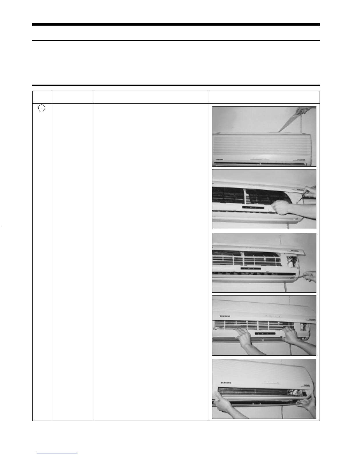
2-1 Indoor Unit
No Parts Procedure Remark
1
Front Grille 1) Stop the air conditioner operation and block the
main power.
2) Seperate tape of front panel upper.
3) Contract the second finger to the left, and right
handle and pull to open the inlet grille.
4) Take the left and right filter out.
5) Loosen one of the right fixing screw and seperate the terminal cover.
6) Loosen three fixing screws of front grille.
7) Pull the upper left and right of discharge softly
for the outside cover to be pulled out.
8) Pull softly the lower part of discharge and push
it up.
Caution;
Assemble the front panel and fix the
hooks of left and right.
3
No Parts Procedure Remark
2
3
Ass’y Tray Drain.
Electrical Parts
(Main PCB)
1) Do “1”, above.
Separate the drain hose from the extension
drain hose.
2) Take the display PCB out.
(Center of indoor unit)
3) Loosen three fixing screws of left and right
4) Pull tray drain out from the back body.
1) Do “1”, “2”, above
2) Take all the connector of PCB upper side out.
3) Separate the outdoor unit connection wire from
the terminal block.
4) If pulling the Main PCB up. it will be taken out.
(Separate the TRANS hook. it before).
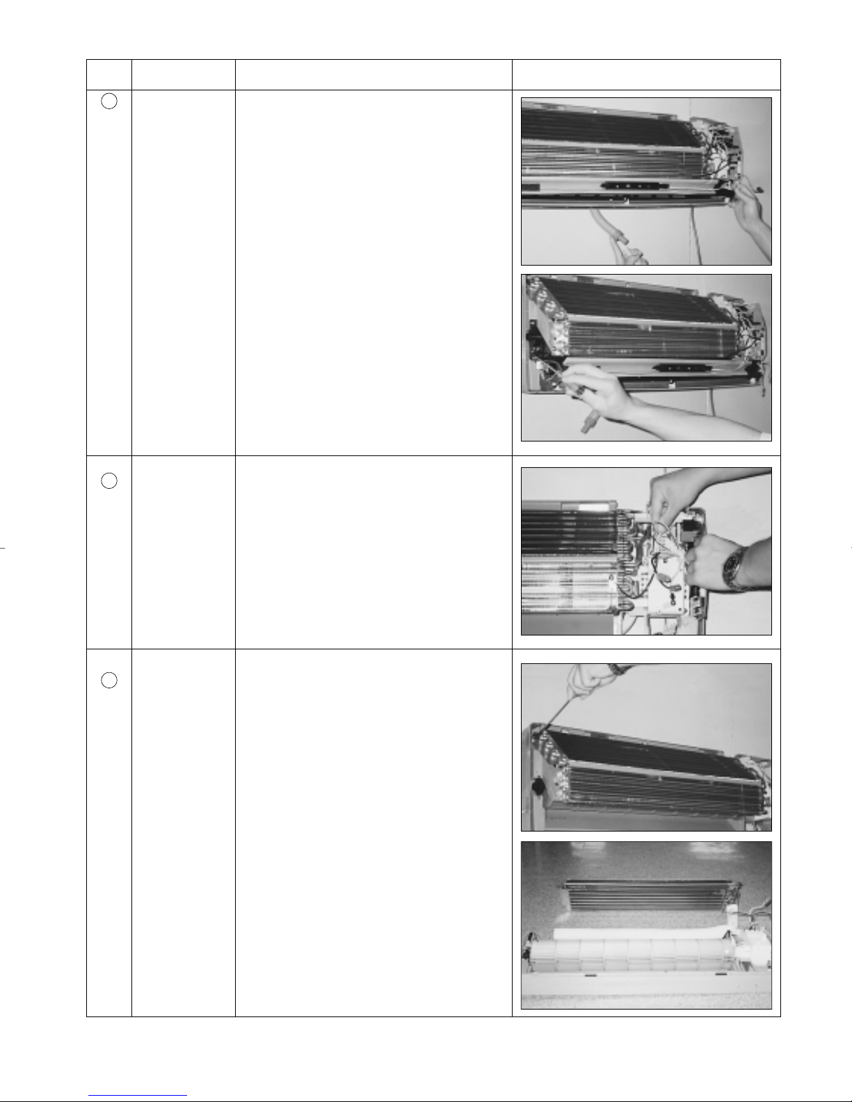
4
Heat Exchanger
1) Do “1” and “2”, “3”, above
2) Loosen two fixing earth screws of right side.
3) Separate the connection pipe.
4) Separate the bush body at the upper side and
holder at the rearside.
5) Loosen the two fixing screws of left side.
6) Lifting the heat exchanger up a little to push the
up side for separation from the indoor unit.
4
No Parts Procedure Remark
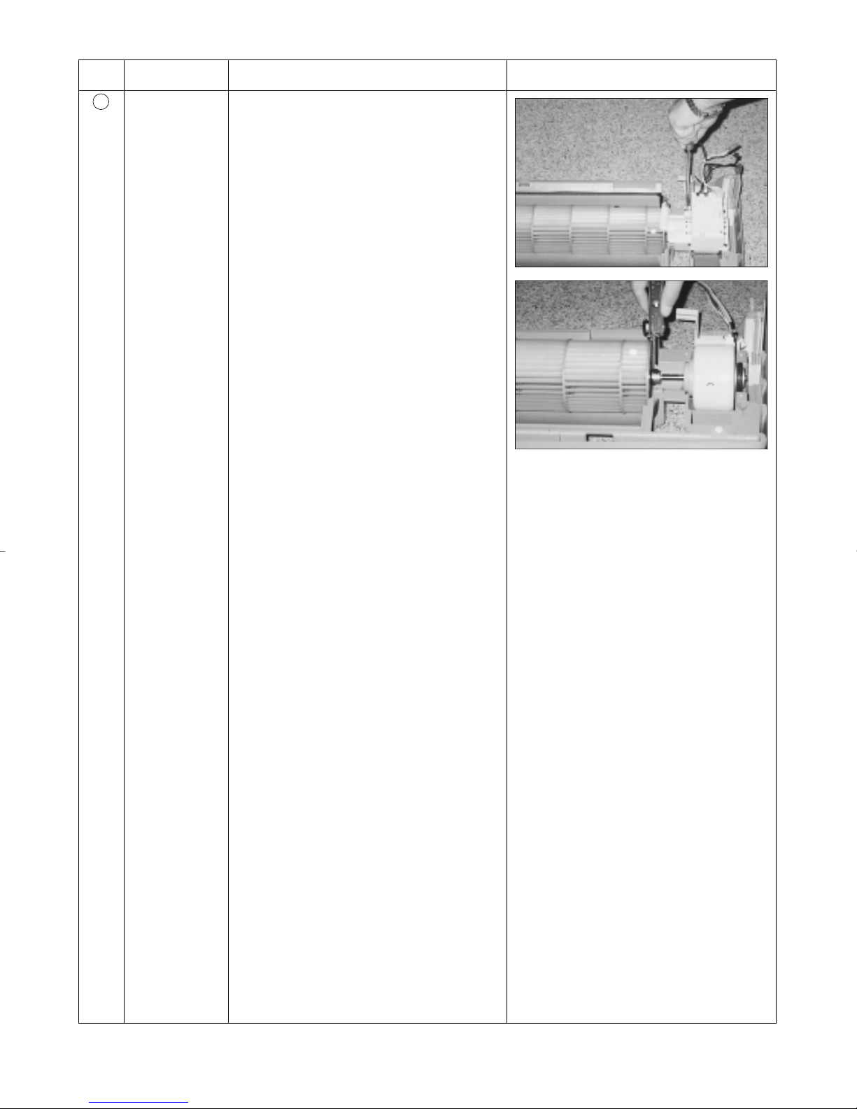
5
Fan Motor and
1) Do “1” “2” ”3” “4”, above.
Cross Fan
2) Loosen the fixing three screws and separate the
motor holder.
3) Loosen the fixing screw of fan motor.
(By use of M3 wrench)
4) Separate the fan motor from the fan.
5) Separate the fan from the left holder bearing.
5
2-2 Outdoor Unit
No Parts Procedure Remark
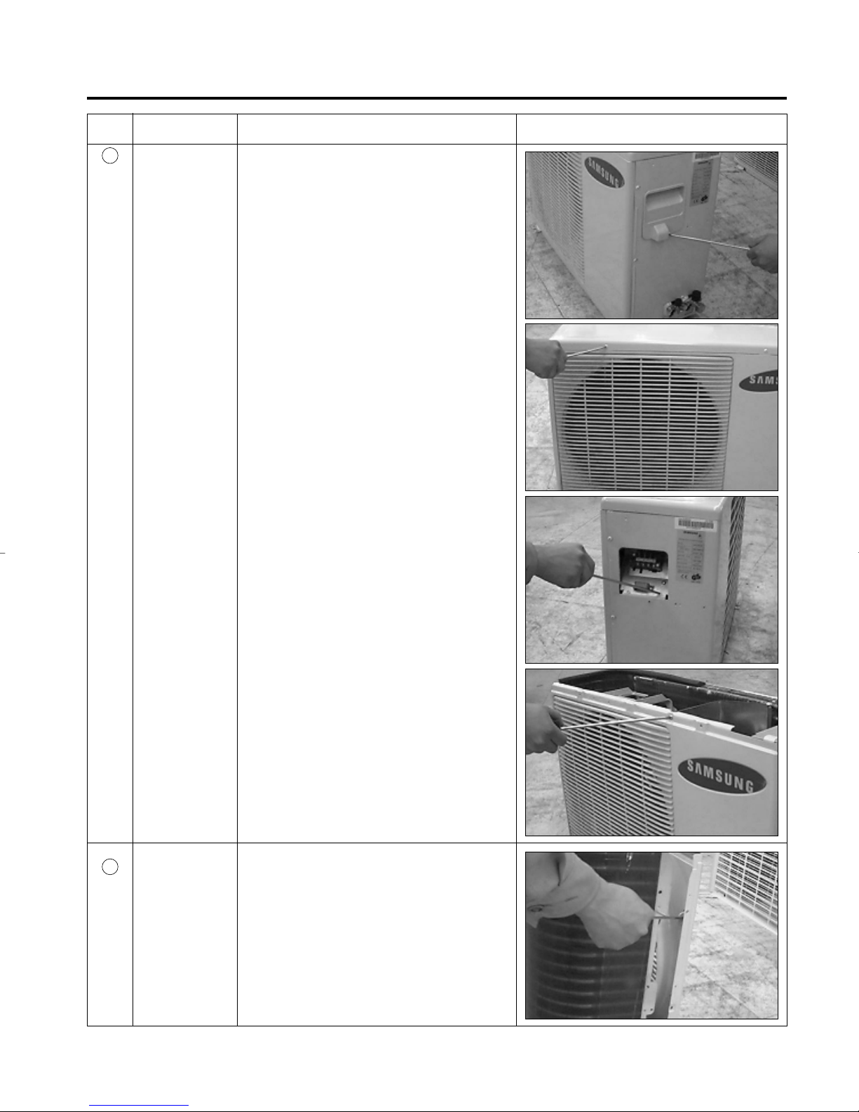
1
Common Work
1) Loosen the fixing screw and separate the cover
E-parts.
2) Separate the connection wire from the terminal
block.
3) Loosen three fixing screws and separate the
upper cabinet.
2
Fan and Motor
4) Loosen the two fixing screws of Ass'y E-part.
5) Loosen seven fixing screws and separate the
side cabinet.
1) Do “1”, above.
2) Loosen two fixing screw, of the front cabinet.
3) Push the brackets of the outer cover to sepa-
rate the protection mesh from the rear side of front
cabinet.
6
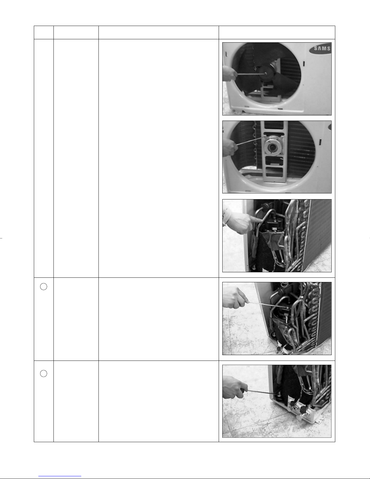
No Parts Procedure Remark
4) Remove the nut flange (Turn to the right to
remove, as it is a left hand screw)
5) Separate the fan.
6) Loosen four fixing screws to separate the motor.
3
4
Heat Exchanger
Compressor
1) Do “1”, above.
2) Loosen three fixing screws of left and right side.
3) Disassemble the inlet and outlet pipe by welding.
4) Separate the heat exchanger.
1) Do “1”, above.
2) Open the terminal cover of compressor and
unscrew the connection terminal.
3) Disassemble the inlet and outlet pipe of compressor by welding.
4) Disassemble the inlet and outlet pipe of condenser by welding
5) Loosen the three bolts of the lower part.
6) separate the compressor.
7
 Loading...